CN115875478A - Water diversion and outflow device - Google Patents
Water diversion and outflow deviceDownload PDFInfo
- Publication number
- CN115875478A CN115875478ACN202111420257.9ACN202111420257ACN115875478ACN 115875478 ACN115875478 ACN 115875478ACN 202111420257 ACN202111420257 ACN 202111420257ACN 115875478 ACN115875478 ACN 115875478A
- Authority
- CN
- China
- Prior art keywords
- water
- water outlet
- flow
- cavity
- outlet
- Prior art date
- Legal status (The legal status is an assumption and is not a legal conclusion. Google has not performed a legal analysis and makes no representation as to the accuracy of the status listed.)
- Pending
Links
Images


Classifications
- E—FIXED CONSTRUCTIONS
- E03—WATER SUPPLY; SEWERAGE
- E03C—DOMESTIC PLUMBING INSTALLATIONS FOR FRESH WATER OR WASTE WATER; SINKS
- E03C1/00—Domestic plumbing installations for fresh water or waste water; Sinks
- E03C1/02—Plumbing installations for fresh water
- E03C1/04—Water-basin installations specially adapted to wash-basins or baths
- E03C1/0404—Constructional or functional features of the spout
- A—HUMAN NECESSITIES
- A47—FURNITURE; DOMESTIC ARTICLES OR APPLIANCES; COFFEE MILLS; SPICE MILLS; SUCTION CLEANERS IN GENERAL
- A47L—DOMESTIC WASHING OR CLEANING; SUCTION CLEANERS IN GENERAL
- A47L15/00—Washing or rinsing machines for crockery or tableware
- A—HUMAN NECESSITIES
- A47—FURNITURE; DOMESTIC ARTICLES OR APPLIANCES; COFFEE MILLS; SPICE MILLS; SUCTION CLEANERS IN GENERAL
- A47L—DOMESTIC WASHING OR CLEANING; SUCTION CLEANERS IN GENERAL
- A47L15/00—Washing or rinsing machines for crockery or tableware
- A47L15/0065—Washing or rinsing machines for crockery or tableware specially adapted for drinking glasses
- A—HUMAN NECESSITIES
- A47—FURNITURE; DOMESTIC ARTICLES OR APPLIANCES; COFFEE MILLS; SPICE MILLS; SUCTION CLEANERS IN GENERAL
- A47L—DOMESTIC WASHING OR CLEANING; SUCTION CLEANERS IN GENERAL
- A47L15/00—Washing or rinsing machines for crockery or tableware
- A47L15/42—Details
- A47L15/4214—Water supply, recirculation or discharge arrangements; Devices therefor
- A47L15/4217—Fittings for water supply, e.g. valves or plumbing means to connect to cold or warm water lines, aquastops
- A—HUMAN NECESSITIES
- A47—FURNITURE; DOMESTIC ARTICLES OR APPLIANCES; COFFEE MILLS; SPICE MILLS; SUCTION CLEANERS IN GENERAL
- A47L—DOMESTIC WASHING OR CLEANING; SUCTION CLEANERS IN GENERAL
- A47L15/00—Washing or rinsing machines for crockery or tableware
- A47L15/42—Details
- A47L15/4214—Water supply, recirculation or discharge arrangements; Devices therefor
- A47L15/4223—Devices for water discharge, e.g. devices to prevent siphoning, non-return valves
- E—FIXED CONSTRUCTIONS
- E03—WATER SUPPLY; SEWERAGE
- E03C—DOMESTIC PLUMBING INSTALLATIONS FOR FRESH WATER OR WASTE WATER; SINKS
- E03C1/00—Domestic plumbing installations for fresh water or waste water; Sinks
- E03C1/02—Plumbing installations for fresh water
- E03C1/04—Water-basin installations specially adapted to wash-basins or baths
- E03C1/041—Water-basin installations specially adapted to wash-basins or baths having provisions against scalding, e.g. temperature limiting devices, external covers
- F—MECHANICAL ENGINEERING; LIGHTING; HEATING; WEAPONS; BLASTING
- F16—ENGINEERING ELEMENTS AND UNITS; GENERAL MEASURES FOR PRODUCING AND MAINTAINING EFFECTIVE FUNCTIONING OF MACHINES OR INSTALLATIONS; THERMAL INSULATION IN GENERAL
- F16K—VALVES; TAPS; COCKS; ACTUATING-FLOATS; DEVICES FOR VENTING OR AERATING
- F16K11/00—Multiple-way valves, e.g. mixing valves; Pipe fittings incorporating such valves
- F16K11/02—Multiple-way valves, e.g. mixing valves; Pipe fittings incorporating such valves with all movable sealing faces moving as one unit
- F16K11/06—Multiple-way valves, e.g. mixing valves; Pipe fittings incorporating such valves with all movable sealing faces moving as one unit comprising only sliding valves, i.e. sliding closure elements
- F16K11/078—Multiple-way valves, e.g. mixing valves; Pipe fittings incorporating such valves with all movable sealing faces moving as one unit comprising only sliding valves, i.e. sliding closure elements with pivoted and linearly movable closure members
- F16K11/0782—Single-lever operated mixing valves with closure members having flat sealing faces
- F16K11/0787—Single-lever operated mixing valves with closure members having flat sealing faces with both the supply and the discharge passages being on the same side of the closure members
- E—FIXED CONSTRUCTIONS
- E03—WATER SUPPLY; SEWERAGE
- E03C—DOMESTIC PLUMBING INSTALLATIONS FOR FRESH WATER OR WASTE WATER; SINKS
- E03C1/00—Domestic plumbing installations for fresh water or waste water; Sinks
- E03C1/02—Plumbing installations for fresh water
- E03C1/04—Water-basin installations specially adapted to wash-basins or baths
- E03C2001/0414—Water-basin installations specially adapted to wash-basins or baths allowing different orientations of the spout or the outlet nozzle
- E—FIXED CONSTRUCTIONS
- E03—WATER SUPPLY; SEWERAGE
- E03C—DOMESTIC PLUMBING INSTALLATIONS FOR FRESH WATER OR WASTE WATER; SINKS
- E03C2201/00—Details, devices or methods not otherwise provided for
- E03C2201/30—Diverter valves in faucets or taps
- Y—GENERAL TAGGING OF NEW TECHNOLOGICAL DEVELOPMENTS; GENERAL TAGGING OF CROSS-SECTIONAL TECHNOLOGIES SPANNING OVER SEVERAL SECTIONS OF THE IPC; TECHNICAL SUBJECTS COVERED BY FORMER USPC CROSS-REFERENCE ART COLLECTIONS [XRACs] AND DIGESTS
- Y02—TECHNOLOGIES OR APPLICATIONS FOR MITIGATION OR ADAPTATION AGAINST CLIMATE CHANGE
- Y02B—CLIMATE CHANGE MITIGATION TECHNOLOGIES RELATED TO BUILDINGS, e.g. HOUSING, HOUSE APPLIANCES OR RELATED END-USER APPLICATIONS
- Y02B40/00—Technologies aiming at improving the efficiency of home appliances, e.g. induction cooking or efficient technologies for refrigerators, freezers or dish washers
Landscapes
- Engineering & Computer Science (AREA)
- Water Supply & Treatment (AREA)
- Public Health (AREA)
- Health & Medical Sciences (AREA)
- Life Sciences & Earth Sciences (AREA)
- Hydrology & Water Resources (AREA)
- General Engineering & Computer Science (AREA)
- Mechanical Engineering (AREA)
- Multiple-Way Valves (AREA)
- Nozzles (AREA)
- Paper (AREA)
- Devices That Are Associated With Refrigeration Equipment (AREA)
- Domestic Plumbing Installations (AREA)
Abstract
Description
Translated fromChinese技术领域technical field
本发明属于洁具技术领域,特指一种分流出水装置。The invention belongs to the technical field of sanitary ware, in particular to a diverting water outlet device.
背景技术Background technique
目前,随着对食品卫生越来越重视,对杯子的清洗也越来越精细。特别是洁具设备行业,洗杯器的应用越来越广泛。洗杯器相关也有很多专利,例如专利号为2018112269178的专利,其具体公开了一种杯子清洗器的结构。At present, as more and more attention is paid to food hygiene, the cleaning of cups is becoming more and more refined. Especially in the sanitary ware equipment industry, the application of cup washers is becoming more and more extensive. There are also many patents related to the cup washer, such as the patent No. 2018112269178, which specifically discloses the structure of a cup washer.
但是在实际使用中,涉及到清洁时洗杯器往往不是单独使用的,经常还要再搭配一个水龙头。而现有的水龙头和洗杯器都是分开两个管路进行;但是在实际使用中,两者往往都是搭配使用,但是如果分开两个管路则会增加管路的复杂程度,和增加安装成本。But in actual use, when it comes to cleaning, the glass washer is often not used alone, and it is often paired with a faucet. However, the existing faucet and glass washer are separated into two pipelines; but in actual use, both are often used together, but if the two pipelines are separated, the complexity of the pipeline will be increased, and the increase in Installation costs.
发明内容Contents of the invention
本发明的目的是提供一种能够通过一个开关独立供应两个管路的分流出水装置。The object of the present invention is to provide a split water outlet device capable of independently supplying two pipelines through one switch.
本发明的目的是这样实现的,一种分流出水装置,用于将水流分别引向第一出水构件和第二出水构件,其包括有:The purpose of the present invention is achieved in this way, a diversion water outlet device, used to guide the water flow to the first water outlet member and the second water outlet member respectively, which includes:
装置本体,其内部设置有分流座;分流座将装置本体的内部分隔为第一出水腔、第二出水腔、容置腔和引入腔;The device body is provided with a diverter seat inside; the diverter seat divides the interior of the device body into a first water outlet chamber, a second water outlet chamber, an accommodating chamber and an introduction chamber;
其中,所述第一出水腔将水流引向第一出水构件,第一出水腔和容置腔之间设置有第一流道;Wherein, the first water outlet chamber guides the water flow to the first water outlet member, and a first flow channel is provided between the first water outlet chamber and the accommodation chamber;
所述第二出水腔将水流引向第二出水构件,第二出水腔和容置腔之间设置有第二流道;以及The second water outlet chamber guides the water flow to the second water outlet member, and a second flow channel is provided between the second water outlet chamber and the accommodation chamber; and
容置腔和引入腔之间设置有进水通道;A water inlet channel is arranged between the accommodating cavity and the introducing cavity;
且,所述分流出水装置还包括有分水阀芯,其配置在容置腔内,用于将水流分别引向所述第一流道和第二流道;分水阀芯至少具有:Moreover, the water diversion device also includes a water diversion valve core, which is arranged in the accommodating cavity, and is used to guide the water flow to the first flow channel and the second flow channel respectively; the water diversion valve core has at least:
阀体,其具有对应所述进水通道的进水口,和分别与所述第一流道和第二流道对应的第一出水口和第二出水口;以及a valve body having a water inlet corresponding to the water inlet channel, and a first water outlet and a second water outlet respectively corresponding to the first flow channel and the second flow channel; and
阀杆,其一端至少部分穿设在阀体内;并通过转动单独打开第一出水口或者第二出水口;A valve stem, one end of which is at least partly pierced in the valve body; and the first water outlet or the second water outlet is opened independently by rotation;
使得所述分流出水装置至少有以下两种状态:The water diversion device has at least the following two states:
第一出水口打开时,水流经进水口、第一出水口流向所述第一流道;或者When the first water outlet is opened, water flows through the water inlet and the first water outlet to the first flow channel; or
第二出水口打开时,水流经进水口、第二出水口流向所述第二流道。When the second water outlet is opened, water flows through the water inlet and the second water outlet to the second flow channel.
优选地,所述分流座具有:Preferably, the diverter seat has:
分流上壁,用于分隔所述容置腔与第一出水腔;且,所述分流上壁与装置本体内壁面之间设置有第一流道;以及A diversion upper wall is used to separate the accommodating chamber from the first water outlet chamber; and, a first flow channel is provided between the diversion upper wall and the inner wall of the device body; and
分流下壁,用于分隔所述引入腔与第二出水腔,并使得水流从引入腔进入后穿过分流下壁再进入容置腔内。The lower divider wall is used to separate the introduction chamber from the second water outlet chamber, and allows the water flow to pass through the lower divider wall and then enter the accommodating chamber after entering from the introduction chamber.
优选地,所述分流座具有第二流道,其贯穿所述分流座并分别与所述第二出水腔和第二出水口相连通。Preferably, the diverter seat has a second flow channel, which runs through the diverter seat and communicates with the second water outlet cavity and the second water outlet respectively.
优选地,所述进水通道设置在分流座内,其包括有热水流道和冷水流道;Preferably, the water inlet channel is set in the diverter seat, which includes a hot water flow channel and a cold water flow channel;
所述进水口包括有:The water inlet includes:
冷水进口,其与所述冷水流道的其中一端连通;以及a cold water inlet communicating with one end of the cold water channel; and
热水进口,其与所述热水流道的其中一端连通。The hot water inlet communicates with one end of the hot water flow channel.
优选地,所述热水流道和/或冷水流道是具有直角拐角的流道。Preferably, the hot water flow channel and/or the cold water flow channel are flow channels with right-angled corners.
优选地,所述阀杆至少部分伸出所述装置本体;Preferably, the valve stem at least partially protrudes from the device body;
所述分流出水装置还具有手柄,手柄内成型有驱动孔,手柄转动时通过驱动孔驱动阀杆转动。The diverting water outlet device also has a handle, and a driving hole is formed in the handle, and the valve stem is driven to rotate through the driving hole when the handle is rotated.
优选地,所述第一出水构件是龙头,其出水端可转动至洗杯器的上方;以及Preferably, the first water outlet member is a faucet, the water outlet end of which can be turned to the top of the glass washer; and
所述第二出水构件是洗杯器;使得待龙头的出水端移转动至洗杯器上方时,洗杯器和龙头能分别清洗器皿的内侧面和外侧面。The second water outlet component is a glass washer; when the water outlet of the faucet moves above the glass washer, the glass washer and the faucet can respectively clean the inner and outer surfaces of the vessel.
优选地,所述洗杯器具有:Preferably, the cup washer has:
托盘,其具有供水流出托盘的出口;a tray having an outlet for the water supply to flow out of the tray;
弹性出水器,其具有若干道喷淋臂,喷淋臂用于将第二出水腔内的水喷向待清洁物。The elastic water outlet has several spray arms, and the spray arms are used to spray the water in the second water outlet chamber to the objects to be cleaned.
优选地,所述装置本体一端具有洗杯器安装位,安装位上端是倾斜面,用于使得水分能经所述出口流出;Preferably, one end of the device body has a cup washer installation position, and the upper end of the installation position is an inclined surface for allowing water to flow out through the outlet;
或者,所述托盘内下端面具有斜面,使得水分能经所述出口流。Alternatively, the inner lower end surface of the tray has a slope, so that the water can flow through the outlet.
优选地,所述托盘上还配置有紧固件,紧固件同时穿过所述托盘和洗杯器安装位。Preferably, fasteners are also arranged on the tray, and the fasteners pass through the tray and the installation position of the glass washer at the same time.
本发明相比现有技术突出且有益的技术效果是:Compared with the prior art, the present invention has outstanding and beneficial technical effects as follows:
1、本发明能够在一个装置上分别独立管理两个出水构件的出水装置,甚至还可以单独针对两个出水构件中的任意其中一个都能提供冷水、热水和冷热混合水三种状态。特别是通过将第一出水构件设置为龙头,第二出水构件设置为洗杯器,从而可以实现单独针对龙头或者洗杯器的单独供水。而且供水的状态还具有冷水、热水和冷热混合水三种出水状态。而且是通过一个开关独立控制两个出水构件的出水。1. The present invention can independently manage the water outlet devices of the two water outlet components on one device, and can even provide three states of cold water, hot water and mixed hot and cold water for any one of the two water outlet components. In particular, by setting the first water outlet member as a faucet and the second water outlet member as a glass washer, separate water supply for the faucet or the glass washer can be realized. Moreover, the state of water supply also has three water outlet states: cold water, hot water, and cold and hot mixed water. Moreover, the water outlets of the two water outlet components are independently controlled by a switch.
2、本发明对出水构件的要求低,能够适用于各种出水构件,而且可以随意组合,相较于现有的出水器,更加集成化、更加便捷。2. The present invention has low requirements on the water outlet components, can be applied to various water outlet components, and can be combined at will. Compared with the existing water outlets, it is more integrated and convenient.
3、本发明的洗杯器其上表面在安装后具有倾斜面,倾斜面能够让水分从出口处排出,防止积水。3. The upper surface of the cup washer of the present invention has an inclined surface after installation, and the inclined surface can allow water to be discharged from the outlet to prevent water accumulation.
4、本发明的洗杯器与装置本体是通过紧固件连接的,这样可以防止洗杯器转动。4. The cup washer of the present invention is connected to the device body through fasteners, which can prevent the cup washer from rotating.
附图说明Description of drawings
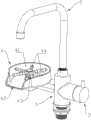
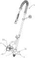
图1是洗杯器和水龙头配合的分流出水装置之一;Fig. 1 is one of the split water outlet devices matched by the cup washer and the faucet;
图2是洗杯器和水龙头配合的分流出水装置之二;Fig. 2 is the second of the split water outlet device matched with the cup washer and the faucet;
图3是装置本体的立体图;Fig. 3 is a perspective view of the device body;
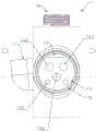
图4是装置本体的仰视图;Fig. 4 is the bottom view of device body;
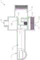
图5是图4中A-A方向的剖视图;Fig. 5 is the sectional view of A-A direction in Fig. 4;
图6是图4中B-B方向的剖视图;Fig. 6 is the sectional view of B-B direction in Fig. 4;
图7是图4中C-C方向的剖视图;Fig. 7 is the sectional view of C-C direction in Fig. 4;
图8是装置本体的侧视图;Figure 8 is a side view of the device body;
图9是图8中D-D方向的剖视图;Fig. 9 is a sectional view of D-D direction in Fig. 8;
图10是图1隐藏洗杯器和水龙头之后的爆炸图之一;Figure 10 is one of the exploded views after hiding the glass washer and faucet in Figure 1;
图11是图1隐藏洗杯器和水龙头之后的爆炸图之二;Figure 11 is the second exploded view after the glass washer and faucet are hidden in Figure 1;
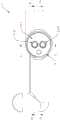
图12是手柄和分水阀芯的爆炸图;Figure 12 is an exploded view of the handle and the water diversion valve core;
图13是变形例二的结构示意图之一;Fig. 13 is one of the structural schematic diagrams of the second modification;
图14是变形例二的结构示意图之二;Fig. 14 is the second structural schematic diagram of the second modification;
图15是分水阀芯的立体图;以及Figure 15 is a perspective view of the water diversion valve core; and
图16是分水阀芯应用在水龙头时的示意图。Fig. 16 is a schematic diagram of the water diversion valve core applied to a faucet.
图中:1-装置本体;2-分水阀芯;3-手柄;4-洗杯器;5-龙头;11-引入腔;12-第一出水腔;13-第二出水腔;14-分流座;15-第一流道;16-容置腔;17-安装位;21-阀体;22-第一出水口;23-第二出水口;24-冷水进口;25-热水进口;26-阀杆;28-定位凸柱;31-驱动孔;32-驱动杆;41-托盘;42-出口;43-弹性出水器;44-喷淋臂;141-分流上壁;142-第二流道;143-热水流道;144-冷水流道;145-定位孔;146-排水间隙;147-分流下壁。In the figure: 1-device body; 2-water diversion valve core; 3-handle; 4-glass washer; 5-faucet; 11-introduction chamber; 12-first water outlet chamber; 13-second water outlet chamber; Diverter seat; 15-first flow channel; 16-accommodating cavity; 17-installation position; 21-valve body; 22-first water outlet; 23-second water outlet; 24-cold water inlet; 25-hot water inlet; 26-valve stem; 28-positioning boss; 31-drive hole; 32-drive rod; 41-tray; 42-exit; 43-elastic water outlet; 44-spray arm; Second runner; 143-hot water runner; 144-cold water runner; 145-positioning hole; 146-drainage gap; 147-distribution lower wall.
具体实施方式Detailed ways
下面以具体实施例对本发明做进一步描述。The present invention will be further described below with specific examples.
为了解决背景技术中所提及的技术问题,本发明具体提供了一种能够在一个装置上分别独立管理两个出水构件的出水装置,甚至还可以单独针对某个出水构件提供冷水、热水和冷热混合水。In order to solve the technical problems mentioned in the background technology, the present invention specifically provides a water outlet device that can independently manage two water outlet components on one device, and can even provide cold water, hot water and Mix hot and cold water.
接下来通过不同的分流出水装置的结构具体说明本发明的技术方案。Next, the technical solution of the present invention will be specifically described through the structures of different water diversion devices.
【实施例一】[Example 1]
如图1和图2所示,图1和图2都是洗杯器4和龙头5配合的分流出水装置。图1和图2的区别在于龙头5的款式不同。As shown in Fig. 1 and Fig. 2, both Fig. 1 and Fig. 2 are water diversion devices in which the
从上述两幅图中可以看出,在本实施例中所述的分流出水装置,其具有装置本体1。同时结合图3,图3是本实施例中,装置本体1的立体图;从图1-3中可以看到,装置本体1总体呈柱状体,而且在实际应用中是水平布置的。It can be seen from the above two figures that the split water outlet device described in this embodiment has a device body 1 . In conjunction with FIG. 3 , FIG. 3 is a perspective view of the device body 1 in this embodiment; as can be seen from FIGS. 1-3 , the device body 1 is generally columnar and is arranged horizontally in practical applications.
以图1和图2所在视角来看,在装置本体1的中部朝上的位置连接有一个第一出水构件,在本实施例中第一出水构件也就是一个龙头5,而且正如上文可知,图1和图2上的龙头5的外形还不同,这样可以根据实际应用场景和用户喜好进行搭配。From the perspective of Figures 1 and 2, a first water outlet member is connected to the upward position in the middle of the device body 1. In this embodiment, the first water outlet member is also a
另外在装置本体1的中部朝下的位置有一个用于外接管道的接口,这个接口是用于外接市政的自来水,当然在本实施例中由于还要实现冷热水,因此这个接口在实际使用中,还要接入热水。In addition, there is an interface for external pipes in the downward position of the middle part of the device body 1. This interface is used for external municipal tap water. Of course, in this embodiment, cold and hot water will also be realized, so this interface is used in actual use. , but also access to hot water.
而且,在装置本体1的左侧连接有一个第二出水构件,在本实施例中也就是洗杯器4。在本实施例中,第一出水构件是龙头5,第二出水构件是洗杯器4,当然在实际使用中还有其他组合的方式,具体在下文其他实施例中有介绍。Moreover, a second water outlet member, which is the
另外,在本实施例中,龙头5是可转动的设计,而且龙头5的出水端可转动至洗杯器4的上方,同时搭配洗杯器4的使用,使得待龙头5的出水端移转动至洗杯器4上方时,洗杯器4和龙头5能分别清洗器皿的内侧面和外侧面。这样能够增加清洗器皿的效率。In addition, in this embodiment, the
同时,从图1和图2中可以看到,在装置本体1的左侧安装有一个手柄3。Meanwhile, as can be seen from FIGS. 1 and 2 , a
因此本实施例想要达到的技术效果在于通过分流出水装置将水流分别引向第一出水构件和第二出水构件。Therefore, the intended technical effect of this embodiment is to guide the water flow to the first water outlet member and the second water outlet member respectively through the diverting water outlet device.
具体实现的原理是:如图3所示,装置本体1具有用于供水流入的引入腔11,相当于引入流道,是用于将水引向第一出水构件的第一出水腔12、将水引向第二出水构件的第二出水腔13和一个与手柄3连接的端口。The principle of specific implementation is: as shown in Figure 3, the device body 1 has an
再如图4所示,图4是装置本体1的仰视图,可以看到装置本体1的底部。As shown in FIG. 4 again, FIG. 4 is a bottom view of the device body 1 , and the bottom of the device body 1 can be seen.
从图4中可以看到,所述的装置本体1在引入腔11末端具有一个平面挡住了引入腔11,而在这个平面上共有三个孔,其中两个较大的孔分别是热水流道143和冷水流道144。为了方便描述,将图4中位于上侧的孔定义为热水流道143,并将位于下侧的孔定义为冷水流道144。从图4中可以看到,上述的平面也就是分流下壁147。As can be seen from Figure 4, the device body 1 has a plane at the end of the
再看图5,图5是图4中A-A方向的剖视图;具体的说是从冷水流道144的中心再水平剖过去之后所得的视图。Looking at Fig. 5 again, Fig. 5 is a cross-sectional view along A-A direction in Fig. 4;
再看图6,图6是图4中B-B方向的剖视图;具体的说是从热水流道143的中心再水平剖过去之后所得的视图。Looking at Fig. 6 again, Fig. 6 is a cross-sectional view along the B-B direction in Fig. 4; specifically, it is a view obtained after a horizontal cross-section from the center of the hot
而且结合图5和图6,可以看到所述的装置本体1的内部具有引入腔11、用于将水引向第一出水构件的第一出水腔12、将水引向第二出水构件的第二出水腔13、一个与手柄3连接的端口和一个分流座14。分流座14位于所述第一出水腔12、第二出水腔13和引入腔11的交汇处。5 and 6, it can be seen that the inside of the device body 1 has an
从图5和图6中可以看出,分流座14内成型有冷水流道144和热水流道143。而且从图5中可以看到,所述的冷水流道144是一个具有直角拐角的流道;从图6中可以看到,所述的热水流道143是一个具有直角拐角的流道。It can be seen from FIG. 5 and FIG. 6 that a cold
再看图7,图7是图4中C-C方向的剖视图;从图7中可以看到,冷水流道144和热水流道143分别与引入腔11是连通的,而且冷水流道144和热水流道143靠近引入腔11一侧表面是与装置本体1连接的,这样水流就只能从冷水流道144和热水流道143进入。因此需要指出的是,在本实施例中,热水流道143是需要专门接入热的自来水,本分流出水装置本身不加热水流。See Fig. 7 again, Fig. 7 is the cross-sectional view of C-C direction in Fig. 4; Can see from Fig. 7,
而且如图5和图6所示,所述热水流道143和冷水流道144都是将引入腔11中水流引向分流座14的左侧腔室。而左侧的腔室内则用于放置一个分水阀芯2,其用于将水流分别引向所述第一出水腔12和第二出水腔13。And as shown in FIG. 5 and FIG. 6 , both the hot
具体如图10所示,图10是图1隐藏洗杯器4和龙头5之后的爆炸图之一;再结合图11,图11是图1隐藏洗杯器4和龙头5之后的爆炸图之二。从图11和图12中可以看到,分水阀芯2是配置在分流座14的左侧腔室内,也就是下文所述的容置腔16内的。Specifically as shown in Figure 10, Figure 10 is one of the exploded views after the
同时所述分水阀芯2具有:At the same time, the water
阀体21,其具有供水进入引入腔11内的进水口,和分别与所述第一出水腔12和第二出水腔13对应的第一出水口22和第二出水口23;以及A
阀杆26,其转动穿设在阀体21内,并通过转动单独打开第一出水口22或者第二出水口23。The valve stem 26 is rotatably installed in the
使得所述分流出水装置至少有以下两种状态:The water diversion device has at least the following two states:
第一出水口22打开时,水流经进水口、第一出水口22流向所述第一流道15;或者When the
第二出水口23打开时,水流经进水口、第二出水口23流向所述第二流道142。When the
另外如图10所示,所述阀杆26至少部分伸出所述装置本体1;然后再看图11,所述分流出水装置还具有手柄3,手柄3内成型有驱动孔31,手柄外成型有驱动杆32;手柄3转动时通过驱动孔31驱动阀杆26转动,从而实现不同状态之间切换。而且图10-12所示,驱动杆32表面是具有齿条的,所述驱动孔31的内表面是有齿槽的,通过齿槽与齿条的配合,来实现手柄3对阀杆26的驱动。In addition, as shown in Figure 10, the
特别的,再结合图12,如图12是手柄3和分水阀芯2的爆炸图。In particular, combined with FIG. 12 , FIG. 12 is an exploded view of the
从图12可知,在本实施例中,所述进水口包括有:As can be seen from Figure 12, in this embodiment, the water inlet includes:
冷水进口24,其与所述冷水流道144的其中一端连通;以及A
热水进口25,其与所述热水流道143的其中一端连通。The
另外从图12中可以看到,所述第二出水口23的数量并不局限在一个,特别的在本实施例中第二出水口23的数量是四个,绕设在阀体外缘。In addition, it can be seen from FIG. 12 that the number of the
其中,所述分水阀芯2的相关结构,可以参考中国发明专利,专利号为201320125523X,其具体公开了一种陶瓷阀芯。此时所述的阀杆26功能雷同于该专利文中的拨杆。Wherein, the relevant structure of the water
或者,参考中国发明专利,专利号为2012204650397,其具体公开了一种陶瓷阀芯。Alternatively, refer to the Chinese invention patent, the patent number is 2012204650397, which specifically discloses a ceramic valve core.
或者,参考中国发明专利,专利号为2011104497537,其具体公开了一种陶瓷阀芯。Alternatively, refer to the Chinese invention patent, the patent number is 2011104497537, which specifically discloses a ceramic valve core.
或者,参考中国发明专利,专利号为2019203557068,其具体公开了一种新型分水开关陶瓷阀芯;此时所述的阀杆26功能雷同于该专利文中的转杆。Or, refer to the Chinese invention patent, the patent number is 2019203557068, which specifically discloses a new type of ceramic valve core for water diversion switch; the function of the
另外,在本实施例中,分水阀芯2的功能在于实现提供七种状态,具体是冷水或热水或冷热混合水从第一出水口22流出的三种状态,和冷水或热水或冷热混合水从第二出水口23流出的三种状态,以及最后第一出水口22和第二出水口23同时处于关闭的状态。具体本所述分水阀芯2实现双分水以及是冷水或热水或冷热混合水三种状态的切换的具体结构参考上述两个专利。In addition, in this embodiment, the function of the water
对应到本实施例所述的分流出水装置也具有六种状态,分别是当冷水或热水或冷热混合水从第一出水构件流出时的三种状态,和当冷水或热水或冷热混合水从第二出水构件流出时的三种状态,以及第一出水构件和第二出水构件均处于关闭的状态,一共合计七种状态。Corresponding to the diverging water outlet device described in this embodiment, it also has six states, which are three states when cold water or hot water or cold and hot mixed water flow out from the first water outlet member, and when cold water or hot water or cold water The three states when the hot mixed water flows out from the second water outlet member, and the state that both the first water outlet member and the second water outlet member are closed, totally seven states.
而状态切换的过程是通过图1、图2、图10和图11中所示的手柄3,由手柄3转动分水阀芯2的阀杆26来实现切换的。And the process of state switching is through the
同时,如图5、图6和图10所示,所述装置本体1的一端成型有容置腔16,所述分水阀芯2配置在所述容置腔16内;并可以设计成往左侧旋转是控制洗杯器4出水,往右侧旋转是控制龙头5出水,或者反过来也可以;当然当处于如图1和图2所示的位置时,则处于洗杯器4和龙头5都关闭出水的状态。At the same time, as shown in Figure 5, Figure 6 and Figure 10, one end of the device body 1 is formed with an
从图10、11和图12可知,所述分水阀芯2的阀体21具有冷水进口24和热水进口25;重点看图10,所述冷水进口24与所述冷水流道144的另一端连通,具体的说是与冷水流道144的末端相连通,进一步是相对设置,也就是图5中,冷水流道144的右端。It can be seen from Fig. 10, 11 and Fig. 12 that the
且所述热水流道143与所述热水流道143的另一端连通,具体的说是与热水流道143的末端相连通,进一步是相对设置,也就是图6中,热水流道143的右端。And the hot
再看图8,图8是装置本体1的侧视图,也就是图4中的右视图。从图8中可以看到从容置腔16一侧看过去,在分流座14上共分布有五个孔位和一个空隙。Referring to FIG. 8 again, FIG. 8 is a side view of the device body 1 , that is, the right view in FIG. 4 . It can be seen from FIG. 8 that five holes and one gap are distributed on the
其中,上面两个分别是冷水流道144和热水流道143的端面,最下面两个是用于安装分水阀芯2的定位孔145,对应分水阀芯2上具有两个与定位孔145适配的定位凸柱28。Among them, the upper two are the end faces of the cold
而且从图8中可以看到,所述分流座14中间还具有第二流道142。再结合图9,图9是图8中D-D方向的剖视图,也就是从第二流道142的中部水平剖所得的视图。Moreover, it can be seen from FIG. 8 that there is a
从图9中可以看到由下至上依次是容置腔16、分流座14和第二出水腔13。所述分流座14中部有所述第二流道142,第二流道142再往上分别是冷水流道144和热水流道143的横截面,而且冷水流道144的横截面与分流座14的内侧壁之间是有排水间隙146的;同时热水流道143的横截面与分流座14的内侧壁之间也是有排水间隙146的。It can be seen from FIG. 9 that the
因此水流再经第二出水口23出来之后,再经过第二流道142和上述排水间隙146之后,进入到所述第二出水腔13内,从而可以给洗杯器4供水。Therefore, after the water flows out through the
因此所述第二流道142贯穿所述分流座14并分别与所述第二出水腔13和第二出水口23相连通。Therefore, the
另外,从图5和图6可以看出,所述的分流座14还具有分流上壁141,其与所述第一出水腔12的首端之间成型有第一流道15,第一流道15两侧分别与所述第一出水腔12和第一出水口22相连通。In addition, it can be seen from FIG. 5 and FIG. 6 that the
从图5和图6中还可以看出,上述所提及到的分流下壁147同时也出现在图5和图6中,而且所述的分流下壁147用于分隔所述引入腔11与第二出水腔13,并使得水流从引入腔11进入后穿过分流下壁147再进入容置腔16内。It can also be seen from Fig. 5 and Fig. 6 that the above-mentioned distributing
因此,在本实施例中,分流上壁141和分流下壁147组合能够进一步限定水流从引入腔11进入后的流向,进一步说是能够引导水流都先集中往分水阀芯2所在的容置腔16一侧先集中,然后再根据分水阀芯2的状态对应分配到第一出水构件或者第二出水构件。Therefore, in this embodiment, the combination of the diversion
因此水流再经第一出水口22出来之后,再经过第一流道15,进入到所述第一出水腔12内,从而可以给龙头5供水。Therefore, after the water flows out through the
另外从图1和图2可知,所述洗杯器4具有:In addition, it can be seen from Fig. 1 and Fig. 2 that the
托盘41,其具有供水流出托盘41的出口42;a
弹性出水器43,其具有若干道喷淋臂44,喷淋臂44用于将第二出水腔13内的水喷向待清洁物。The
另外从图3中可以看到所述装置本体1的左侧上端面具有一个螺纹孔,而且所述装置本体1一端具有洗杯器的安装位17,洗杯器的安装位17也就是螺纹孔所在位置。而且在本实施例中,安装位上端是倾斜面,用于使得托盘41内的水分能经所述出口42流出。In addition, it can be seen from Fig. 3 that the left upper end surface of the device body 1 has a threaded hole, and one end of the device body 1 has a mounting
所述托盘41上还配置有紧固件,紧固件同时穿过所述托盘41和洗杯器的安装位17,也就是穿过上述螺纹孔。Fasteners are also arranged on the
为了进一步解释分水阀芯的结构特点,除了参考上述四篇专利文和其他附图之外,还可以进一步看图15和图16,图15是分水阀芯的立体图;以及图16是分水阀芯应用在水龙头时的示意图。In order to further explain the structural characteristics of the water diversion valve core, in addition to referring to the above four patent documents and other drawings, you can further look at Figures 15 and 16. Figure 15 is a perspective view of the water diversion valve core; Schematic diagram of the water valve core applied to the faucet.
从图15可知分水阀芯由上至下分别是阀杆26,阀杆26下面是阀体21,另外阀体中两个孔,而这两个孔是第一出水口22。第一出水口22下端是定位凸柱28。It can be seen from FIG. 15 that the water diversion valve core is the valve stem 26 from top to bottom, and the
另外具体看图16,图16是分水阀芯应用在水龙头时的示意图。从该图中可以看到,分水阀芯安装在了水龙头内,分水阀芯的阀杆26与水龙头的转把连接。图中的“C”表示冷水,“H”表示热水;图中标记22的处有一个窗口,与之对应的右侧也有一个窗口,这两个窗口都是第一出水口22,因此从图16中可以看到第一出水口22有出水并从水龙头的右端流出。In addition, see Fig. 16 in detail. Fig. 16 is a schematic diagram of the water diversion valve core applied to a faucet. As can be seen from this figure, the water diversion valve core is installed in the water tap, and the
另外还有在其下端有一个定位凸柱28,并在定位凸柱28的右侧右一个第二出水口23,第二出水口23一侧有箭头朝上的进水口,由于投影关系,此处的进水口是分成了热水进口25和冷水进口24。There is also a
而且从该图中可以看到热水进口25、冷水进口24第一出水口22、第二出水口23都是可以出冷水、热水和冷热混合水。And can see that
需要指出的是图16只是本实施例所述的分发阀芯的其中一个实施例。It should be pointed out that Fig. 16 is only one embodiment of the dispensing valve core described in this embodiment.
接下来具体说明实施例一的工作原理:Next, the working principle of Embodiment 1 will be described in detail:
首先,装置本体1下端的引入腔11接入冷水管道和热水管道,冷水管道和热水管道分别接入冷水流道144和热水流道143。从而冷水分别从冷水管道进入冷水流道144,热水分别从热水管道进入热水流道143。Firstly, the
然后,热水流道143和冷水流道144在转过直角弯之后分别进入容置腔16。此时容置腔16内的分水阀芯2上的冷水进口24和热水进口25分别对应连通冷水流道144和热水流道143。Then, the hot
然后,根据手柄3对阀杆26的作用,此时分水阀芯2会存在上述提到的七种状态。其中,当需要向第一出水构件也就是龙头5供水时,此时阀体21上的第一出水口22处于打开状态,而第二出水口23处于关闭状态。然后由于第一出水口22的打开,此时水流能够经第一流道15进入到第一出水腔12内,从而实现给第一出水构件也就是龙头5供水。Then, according to the action of the
其中,当需要向第二出水构件也就是洗杯器4供水时,此时阀体21上的第二出水口23处于打开状态,而第一出水口22处于关闭状态。然后由于第二出水口23的打开,此时水流能够经第二流道142、排水间隙146最终进入到第二出水腔13内,从而实现给第二出水构件也就是洗杯器4供水。Wherein, when it is necessary to supply water to the second water outlet member, that is, the
【变形例一】【Modification 1】
在实施例一中,是通过洗杯器的安装位17上年配置斜面增加排水性能。而在本实施例中,则是通难过所述托盘41内下端面具有斜面,使得水分能经所述出口42流,这样适用于托盘41是塑料件的情况下使用。In the first embodiment, the
【变形例二】【Modification 2】
如图13和图14所示,图13是变形例二的结构示意图之一;图14是变形例二的结构示意图之二。从上述两个图中可知,相较于图1和图2,在本变形例中,所述图13和图14所示,公开了两种不同款式的龙头5的样式。As shown in FIG. 13 and FIG. 14 , FIG. 13 is one of the structural schematic diagrams of the second modification; FIG. 14 is the second structural schematic diagram of the second modification. It can be seen from the above two figures that, compared with FIG. 1 and FIG. 2 , in this modified example, as shown in FIG. 13 and FIG. 14 , two different styles of
当然本发明还可以通过更换其他的龙头5的款式,应用于不同的使用场景。Of course, the present invention can also be applied to different usage scenarios by replacing other styles of the
【实施例二】[Example 2]
本实施例与实施例一相比,具有如下不同点:Compared with Embodiment 1, this embodiment has the following differences:
所述第一出水构件是洗杯器4;The first water outlet member is a
所述第二出水构件是龙头5。The second water outlet component is the
这样设计的好处在于,能够适应对洗杯器4的高频使用需求。同时也能够证明本发明的第一出水构件和所述第二出水构件是可更换的。甚至还可以是两个出水构件都是洗杯器4,或者两个出水构件都是龙头5。The advantage of such a design is that it can meet the high-frequency usage requirements of the
本说明书中公开的所有特征,或公开的所有方法或过程中的步骤,除了互相排斥的特征和/或步骤以外,均可以以任何方式组合。All features disclosed in this specification, or steps in all methods or processes disclosed, may be combined in any manner, except for mutually exclusive features and/or steps.
本说明书包括任何附加权利要求、摘要和附图中公开的任一特征,除非特别叙述,均可被其他等效或具有类似目的的替代特征加以替换。即,除非特别叙述,每个特征只是一系列等效或类似特征中的一个例子而已。Any feature disclosed in this specification, including any appended claims, abstract and drawings, may, unless expressly stated otherwise, be replaced by alternative features which are equivalent or serve a similar purpose. That is, unless expressly stated otherwise, each feature is one example only of a series of equivalent or similar features.
在本发明的描述中,需要理解的是,术语“一端”、“另一端”、“外侧”、“上”、“内侧”、“水平”、“同轴”、“中央”、“端部”、“长度”、“外端”等指示的方位或位置关系为基于附图所示的方位或位置关系,仅是为了便于描述本发明和简化描述,而不是指示或暗示所指的装置或元件必须具有特定的方位、以特定的方位构造和操作,因此不能理解为对本发明的限制。In describing the present invention, it is to be understood that the terms "one end", "the other end", "outer side", "upper", "inner side", "horizontal", "coaxial", "central", "end ", "length", "outer end" and other indicated orientations or positional relationships are based on the orientations or positional relationships shown in the drawings, which are only for the convenience of describing the present invention and simplifying the description, rather than indicating or implying the referred device or Elements must have certain orientations, be constructed and operate in certain orientations, and therefore should not be construed as limitations on the invention.
此外,在本发明的描述中,“多个”的含义是至少两个,例如两个,三个等,除非另有明确具体的限定。In addition, in the description of the present invention, "plurality" means at least two, such as two, three, etc., unless otherwise specifically defined.
本发明使用的例如“上”、“上方”、“下”、“下方”等表示空间相对位置的术语是出于便于说明的目的来描述如附图中所示的一个单元或特征相对于另一个单元或特征的关系。空间相对位置的术语可以旨在包括设备在使用或工作中除了图中所示方位以外的不同方位。例如,如果将图中的设备翻转,则被描述为位于其他单元或特征“下方”或“之下”的单元将位于其他单元或特征“上方”。因此,示例性术语“下方”可以囊括上方和下方这两种方位。设备可以以其他方式被定向旋转90度或其他朝向,并相应地解释本文使用的与空间相关的描述语。Terms such as "upper", "upper", "lower", "below" and the like used in the present invention to express relative positions in space are for the purpose of description to describe the relative position of one element or feature as shown in the drawings relative to another. A unit or feature relationship. The terms of spatial relative position may be intended to encompass different orientations of the device in use or operation in addition to the orientation depicted in the figures. For example, if the device in the figures is turned over, elements described as "below" or "beneath" other elements or features would then be oriented "above" the other elements or features. Thus, the exemplary term "below" can encompass both an orientation of above and below. A device may be otherwise oriented, rotated 90 degrees or at other orientations, and the spatially relative descriptors used herein interpreted accordingly.
在本发明中,除非另有明确的规定和限定,术语“设置”、“套接”、“连接”、“贯穿”、“插接”等术语应做广义理解,例如,可以是固定连接,也可以是可拆卸连接,或成一体;可以是机械连接,也可以是电连接;可以是直接相连,也可以通过中间媒介间接相连,可以是两个元件内部的连通或两个元件的相互作用关系,除非另有明确的限定。对于本领域的普通技术人员而言,可以根据具体情况理解上述术语在本发明中的具体含义。In the present invention, unless otherwise clearly specified and limited, terms such as "setting", "socketing", "connecting", "through", and "inserting" should be understood in a broad sense, for example, it may be a fixed connection, It can also be detachable connection, or integrated; it can be mechanical connection or electrical connection; it can be directly connected or indirectly connected through an intermediary, and it can be the internal communication of two components or the interaction of two components relationship, unless expressly defined otherwise. Those of ordinary skill in the art can understand the specific meanings of the above terms in the present invention according to specific situations.
故上述实施例仅为本发明的较佳实施例,并非依此限制本发明的保护范围,故:凡依本发明的结构、形状、原理所做的等效变化,均应涵盖于本发明的保护范围之内。Therefore above-mentioned embodiment is only preferred embodiment of the present invention, does not limit protection scope of the present invention accordingly, therefore: all equivalent changes done according to structure, shape, principle of the present invention, all should be covered by the scope of the present invention within the scope of protection.
Claims (10)
Applications Claiming Priority (2)
| Application Number | Priority Date | Filing Date | Title |
|---|---|---|---|
| CN2021223282633 | 2021-09-25 | ||
| CN202122328263 | 2021-09-25 |
Publications (1)
| Publication Number | Publication Date |
|---|---|
| CN115875478Atrue CN115875478A (en) | 2023-03-31 |
Family
ID=79230561
Family Applications (2)
| Application Number | Title | Priority Date | Filing Date |
|---|---|---|---|
| CN202122941794.XUActiveCN216975870U (en) | 2021-09-25 | 2021-11-26 | Water diversion and outflow device |
| CN202111420257.9APendingCN115875478A (en) | 2021-09-25 | 2021-11-26 | Water diversion and outflow device |
Family Applications Before (1)
| Application Number | Title | Priority Date | Filing Date |
|---|---|---|---|
| CN202122941794.XUActiveCN216975870U (en) | 2021-09-25 | 2021-11-26 | Water diversion and outflow device |
Country Status (9)
| Country | Link |
|---|---|
| US (2) | US20230101515A1 (en) |
| EP (1) | EP4155470B1 (en) |
| KR (1) | KR102544282B1 (en) |
| CN (2) | CN216975870U (en) |
| AU (1) | AU2022200374B2 (en) |
| ES (1) | ES2972176T3 (en) |
| GB (1) | GB2611125B (en) |
| TW (1) | TWI808643B (en) |
| WO (1) | WO2023046124A1 (en) |
Families Citing this family (1)
| Publication number | Priority date | Publication date | Assignee | Title |
|---|---|---|---|---|
| CN216975870U (en)* | 2021-09-25 | 2022-07-15 | 浙江盛美洁具有限公司 | Water diversion and outflow device |
Citations (6)
| Publication number | Priority date | Publication date | Assignee | Title |
|---|---|---|---|---|
| US20080142095A1 (en)* | 2006-12-06 | 2008-06-19 | Van Der Linden Wilhelmus Ludov | Faucet |
| CN101846194A (en)* | 2010-05-19 | 2010-09-29 | 开平市国陶卫浴五金制品有限公司 | Tap with two water inlet channels |
| CN203281567U (en)* | 2013-04-24 | 2013-11-13 | 晟宇伟业(北京)科技发展有限公司 | Cup washing device |
| CN112392104A (en)* | 2019-08-19 | 2021-02-23 | 德尔塔阀门公司 | Ware washing device and drain container and faucet assembly for same |
| CN213839672U (en)* | 2020-08-27 | 2021-07-30 | 赵建华 | Water tap device with two water outlet flow passages |
| CN216975870U (en)* | 2021-09-25 | 2022-07-15 | 浙江盛美洁具有限公司 | Water diversion and outflow device |
Family Cites Families (30)
| Publication number | Priority date | Publication date | Assignee | Title |
|---|---|---|---|---|
| IT1173360B (en) | 1984-02-23 | 1987-06-24 | Piralla Renato Spa | MONOBLOCK TAP STRUCTURE WITH SEPARATE WATER DISPENSING |
| KR940001149Y1 (en)* | 1990-08-31 | 1994-03-07 | 아메리칸 스탠다아드 인코포레이팃드 | Valve for removing outlet of faucet |
| DE19648114A1 (en)* | 1996-11-21 | 1998-05-28 | Grohe Armaturen Friedrich | One-handle mixer valve |
| KR20050091237A (en) | 2004-03-11 | 2005-09-15 | 주식회사 혜인교역 | Bib cock |
| US11450331B2 (en) | 2006-07-08 | 2022-09-20 | Staton Techiya, Llc | Personal audio assistant device and method |
| WO2009091135A2 (en) | 2007-12-27 | 2009-07-23 | Sang Tae Park | The bibcock having the cold water and warm water mixture are possible |
| KR100880032B1 (en)* | 2007-12-27 | 2009-01-22 | 박상태 | Hot and cold water mixing taps with cartridges for optional hot and cold water mixing and extraction |
| US20090266913A1 (en) | 2008-04-28 | 2009-10-29 | Pi Kuang Tsai | Holder device for shower head and nozzle |
| CN102037268B (en)* | 2008-05-21 | 2015-09-02 | 印第安纳马斯科公司 | Integrated kitchen faucet side spray sparger and water knockout drum |
| HUP0800431A2 (en)* | 2008-07-14 | 2010-04-28 | Kerox Ipari Es Kereskedelmi Kf | Single-lever mixing faucet operated by turning |
| CN101718353B (en)* | 2009-11-02 | 2012-01-18 | 黎东亮 | Multifunctional stainless steel faucet |
| CN202371216U (en)* | 2011-11-14 | 2012-08-08 | 福建西河卫浴科技有限公司 | Water separator for tap |
| CN202790689U (en)* | 2012-09-12 | 2013-03-13 | 广东汉特科技有限公司 | Ceramic valve core |
| US9376790B2 (en)* | 2013-01-11 | 2016-06-28 | Waxman Consumer Products Group Inc. | Flow diverter and operation of same |
| CN204153220U (en)* | 2014-09-24 | 2015-02-11 | 乔登卫浴(江门)有限公司 | Differential point of washing cup tap |
| CN205592430U (en)* | 2016-03-09 | 2016-09-21 | 翰优企业有限公司 | bathtub faucet |
| KR20180088205A (en)* | 2017-01-26 | 2018-08-03 | 엘지전자 주식회사 | A sink |
| WO2018191079A1 (en)* | 2017-04-10 | 2018-10-18 | Emerson Electric Co. | Faucet with magnetic handle stop |
| US11058604B2 (en)* | 2017-06-12 | 2021-07-13 | Bradley Fixtures Corporation | Combination emergency wash and faucet unit |
| CN207437834U (en)* | 2017-08-09 | 2018-06-01 | 厦门倍杰特科技股份公司 | A kind of triple valve |
| CN208381463U (en)* | 2018-06-25 | 2019-01-15 | 柳荣来 | A kind of basin faucet with mouth washes function |
| US10914056B2 (en)* | 2018-09-14 | 2021-02-09 | Delta Faucet Company | Vessel rinsing apparatus |
| CN209839227U (en)* | 2019-03-20 | 2019-12-24 | 开平市格莱美卫浴配件有限公司 | Novel water diversion switch ceramic valve core |
| CN210562435U (en)* | 2019-06-27 | 2020-05-19 | 佛山市顺德洛基特水暖洁具产品有限公司 | Bar counter faucet |
| CN110274050A (en)* | 2019-07-25 | 2019-09-24 | 路达(厦门)工业有限公司 | The dual-purpose faucet of cross beam type |
| CN110836276A (en)* | 2019-10-29 | 2020-02-25 | 厦门方特卫浴有限公司 | Tap water outlet mechanism |
| CN216519762U (en)* | 2021-09-25 | 2022-05-13 | 浙江盛美洁具有限公司 | Integrated water diversion and outflow device |
| CN216590101U (en)* | 2021-12-30 | 2022-05-24 | 温州市圣雪卫浴有限公司 | Mutually cut integral type and wash a tap |
| CN216715318U (en)* | 2021-12-30 | 2022-06-10 | 温州市圣雪卫浴有限公司 | Press mutual segmentation style and wash a tap |
| CN216715317U (en)* | 2021-12-30 | 2022-06-10 | 温州市圣雪卫浴有限公司 | Mutual split type cup washing faucet |
- 2021
- 2021-11-26CNCN202122941794.XUpatent/CN216975870U/enactiveActive
- 2021-11-26CNCN202111420257.9Apatent/CN115875478A/enactivePending
- 2021-12-23USUS17/645,869patent/US20230101515A1/enactivePending
- 2022
- 2022-01-04ESES22150241Tpatent/ES2972176T3/enactiveActive
- 2022-01-04EPEP22150241.2Apatent/EP4155470B1/enactiveActive
- 2022-01-20AUAU2022200374Apatent/AU2022200374B2/enactiveActive
- 2022-02-10TWTW111104952Apatent/TWI808643B/enactive
- 2022-02-23GBGB2202451.7Apatent/GB2611125B/enactiveActive
- 2022-02-28KRKR1020220026425Apatent/KR102544282B1/enactiveActive
- 2022-09-24USUS18/878,911patent/US12276342B1/enactiveActive
- 2022-09-24WOPCT/CN2022/121142patent/WO2023046124A1/ennot_activeCeased
Patent Citations (6)
| Publication number | Priority date | Publication date | Assignee | Title |
|---|---|---|---|---|
| US20080142095A1 (en)* | 2006-12-06 | 2008-06-19 | Van Der Linden Wilhelmus Ludov | Faucet |
| CN101846194A (en)* | 2010-05-19 | 2010-09-29 | 开平市国陶卫浴五金制品有限公司 | Tap with two water inlet channels |
| CN203281567U (en)* | 2013-04-24 | 2013-11-13 | 晟宇伟业(北京)科技发展有限公司 | Cup washing device |
| CN112392104A (en)* | 2019-08-19 | 2021-02-23 | 德尔塔阀门公司 | Ware washing device and drain container and faucet assembly for same |
| CN213839672U (en)* | 2020-08-27 | 2021-07-30 | 赵建华 | Water tap device with two water outlet flow passages |
| CN216975870U (en)* | 2021-09-25 | 2022-07-15 | 浙江盛美洁具有限公司 | Water diversion and outflow device |
Also Published As
| Publication number | Publication date |
|---|---|
| KR102544282B1 (en) | 2023-06-16 |
| EP4155470B1 (en) | 2023-12-20 |
| GB2611125A (en) | 2023-03-29 |
| US20250137538A1 (en) | 2025-05-01 |
| WO2023046124A1 (en) | 2023-03-30 |
| KR20230044114A (en) | 2023-04-03 |
| TW202312929A (en) | 2023-04-01 |
| TWI808643B (en) | 2023-07-11 |
| EP4155470A1 (en) | 2023-03-29 |
| AU2022200374B2 (en) | 2024-02-08 |
| EP4155470C0 (en) | 2023-12-20 |
| ES2972176T3 (en) | 2024-06-11 |
| GB2611125B (en) | 2024-07-31 |
| US12276342B1 (en) | 2025-04-15 |
| AU2022200374A1 (en) | 2023-04-13 |
| GB202202451D0 (en) | 2022-04-06 |
| CN216975870U (en) | 2022-07-15 |
| US20230101515A1 (en) | 2023-03-30 |
Similar Documents
| Publication | Publication Date | Title |
|---|---|---|
| CN1657177B (en) | Integrated swivel spray aerator with diverter | |
| US7937784B2 (en) | Parent-child showerhead | |
| CN115875478A (en) | Water diversion and outflow device | |
| JP2002165719A (en) | Shower head | |
| CN1527915A (en) | Cartridge for sanitary appliances | |
| CN216519762U (en) | Integrated water diversion and outflow device | |
| EP4345347A1 (en) | A valve core and a pull-out faucet thereof | |
| CN209196172U (en) | A kind of tap valve core | |
| JP5291327B2 (en) | shower head | |
| CN215720984U (en) | Magnetic suction type water tap with multiple water outlets | |
| CN113042232B (en) | Switching type nozzle and control method thereof | |
| US8573256B2 (en) | Revolving switching device | |
| CN210013282U (en) | Constant temperature shower faucet | |
| CN211231703U (en) | A lever-type switching valve and a faucet | |
| CN202290358U (en) | Multifunctional water outlet device | |
| CN209810454U (en) | Water outlet device | |
| CN114319531A (en) | Intelligent closestool, intelligent closestool lid and spray gun and shower nozzle thereof | |
| CN219070166U (en) | Spray arm and dish washer with same | |
| CN220891171U (en) | Novel three-control three-water-outlet large shower faucet | |
| CN114738518B (en) | Valve group and kitchen and toilet appliance | |
| CN112797193B (en) | Tap main body and embedded tap assembly | |
| CN218031573U (en) | Switching structure of flusher | |
| CN119900845B (en) | Shower device capable of evacuating water stored in shower device | |
| JP2959012B2 (en) | Switching valve | |
| CN215568116U (en) | Tap body and tap |
Legal Events
| Date | Code | Title | Description |
|---|---|---|---|
| PB01 | Publication | ||
| PB01 | Publication | ||
| SE01 | Entry into force of request for substantive examination | ||
| SE01 | Entry into force of request for substantive examination |