CN115874955A - A new type of torsion reduction force increase force shock absorption drilling tool - Google Patents
A new type of torsion reduction force increase force shock absorption drilling toolDownload PDFInfo
- Publication number
- CN115874955A CN115874955ACN202111139607.4ACN202111139607ACN115874955ACN 115874955 ACN115874955 ACN 115874955ACN 202111139607 ACN202111139607 ACN 202111139607ACN 115874955 ACN115874955 ACN 115874955A
- Authority
- CN
- China
- Prior art keywords
- force
- straight rod
- drill
- rod spring
- cutting
- Prior art date
- Legal status (The legal status is an assumption and is not a legal conclusion. Google has not performed a legal analysis and makes no representation as to the accuracy of the status listed.)
- Pending
Links
Images


Classifications
- Y—GENERAL TAGGING OF NEW TECHNOLOGICAL DEVELOPMENTS; GENERAL TAGGING OF CROSS-SECTIONAL TECHNOLOGIES SPANNING OVER SEVERAL SECTIONS OF THE IPC; TECHNICAL SUBJECTS COVERED BY FORMER USPC CROSS-REFERENCE ART COLLECTIONS [XRACs] AND DIGESTS
- Y02—TECHNOLOGIES OR APPLICATIONS FOR MITIGATION OR ADAPTATION AGAINST CLIMATE CHANGE
- Y02E—REDUCTION OF GREENHOUSE GAS [GHG] EMISSIONS, RELATED TO ENERGY GENERATION, TRANSMISSION OR DISTRIBUTION
- Y02E10/00—Energy generation through renewable energy sources
- Y02E10/10—Geothermal energy
Landscapes
- Earth Drilling (AREA)
Abstract
Translated fromChinese
Description
Translated fromChinese技术领域technical field
本发明涉及油井、天然气井、地热井、页岩气井等油气田、矿井中钻井工程技术领域,尤其是涉及一种新型扭力的减力或增力、减震钻井的提速技术与工具;依靠水平扭转方向弹力与动力的叠加,实现扭力的减小或增大;依靠积聚动能转化为弹性势能,集中释放积聚后的弹性势能与动能的叠加构成的机械能,实现能量输出的减小或增大;依靠直杆弹簧的弹性扭转伸缩,实现减震;通过减力或增力,减少能量输出或放大能量输出,以及减震的手段,达到钻井提速的目的。The present invention relates to oil wells, natural gas wells, geothermal wells, shale gas wells and other oil and gas fields and drilling engineering technical fields in mines, and in particular to a new type of torque reduction or force increase and shock-absorbing speed-up technology and tools for drilling; relying on horizontal torsion The superposition of directional elastic force and power realizes the reduction or increase of torsion; relying on the accumulation of kinetic energy into elastic potential energy, the concentrated release of mechanical energy formed by the superposition of accumulated elastic potential energy and kinetic energy realizes the reduction or increase of energy output; relying on The elastic torsion and expansion of the straight rod spring realizes shock absorption; the purpose of increasing drilling speed is achieved by reducing or increasing force, reducing energy output or amplifying energy output, and means of shock absorption.
背景技术Background technique
钻井提速技术是提高钻井效率、降低钻井综合成本,获得更大的经济利益,实现效益最大化的重要手段之一。在油气田开发的过程中,钻井工程是一个投入高、风险大、技术密集的环节,投资占勘探开发的50%以上,实践表明:钻井速度提高一倍,总的钻井费用可以降低约25%。Drilling speed increase technology is one of the important means to improve drilling efficiency, reduce comprehensive drilling cost, obtain greater economic benefits and maximize benefits. In the process of oil and gas field development, drilling engineering is a high-investment, high-risk, and technology-intensive link. The investment accounts for more than 50% of exploration and development. Practice shows that if the drilling speed is doubled, the total drilling cost can be reduced by about 25%.
钻井提速技术可以较好地实现更经济环保、更清洁高效地开采地下油气。近几年来经济与时代的进步,环境保护意识增强,要求更经济环保、更清洁高效地开采地下油气已经成为亟待解决的难题,钻井提速技术不仅是目前主要新钻井技术发展方向,而且还是目前钻井科研的主要目标。Drilling speed increase technology can better realize more economical, environmentally friendly, cleaner and more efficient exploitation of underground oil and gas. In recent years, with the progress of the economy and the times, the awareness of environmental protection has increased, and the demand for more economical, environmentally friendly, cleaner and more efficient underground oil and gas exploitation has become an urgent problem to be solved. Drilling speed increase technology is not only the main development direction of new drilling technology, but also the current main goal of research.
发明内容Contents of the invention
本发明的目的在于提供一种新型扭力减力增力减震钻井提速技术及工具,以解决现有技术中存在的钻井作业过程中的机械钻速效率低,无法大幅提高钻井速度的困境,在钻井过程中可重复、多次下井使用。The purpose of the present invention is to provide a new type of technology and tool for increasing drilling speed by reducing force, increasing force, reducing vibration, and solving the predicament that the ROP efficiency in the drilling operation process in the prior art is low, and the drilling speed cannot be greatly increased. During the drilling process, it can be repeated and used in multiple downholes.
本发明提供的一种新型扭力减力增力减震钻井工具,主要包括:The present invention provides a new type of torsion-reducing force-increasing force-absorbing drilling tool, which mainly includes:
上接头:所述结构上端为母扣,与钻铤或钻杆的公扣连接。下端母扣丝扣与上端卡盘的公扣丝扣相连。Upper joint: The upper end of the structure is a box, which is connected with the pin of the drill collar or drill pipe. The female threaded thread at the lower end is connected with the male threaded thread of the upper chuck.
密封件:起到承压密封,并且防止杂质异物从外部落入工具内部。Seal: It acts as a pressure-bearing seal and prevents foreign matter from falling into the inside of the tool from the outside.
滚轴轴承:所述结构,安装在上端卡盘与中心轴之间,在旋转运动过程中,起到减少滚动摩擦阻力的作用;同时,在旋转运动过程中承受轴向负荷,将垂直方向钻杆与钻铤的钻压、动力、动能,从上接头,通过滚轴轴承,中心轴,传递到下接头,再将垂直方向的钻压、动力、动能传递输出到钻头。Roller bearing: the structure is installed between the upper end chuck and the central shaft, and plays the role of reducing rolling friction resistance during the rotation movement; at the same time, it bears the axial load during the rotation movement, and the vertical direction of the drill The drilling pressure, power and kinetic energy of the rod and the drill collar are transmitted from the upper joint to the lower joint through the roller bearing and the central shaft, and then the vertical drilling pressure, power and kinetic energy are transmitted to the drill bit.
上端卡盘,上端丝扣连接上接头,中部为密封段,下端为柱状槽锁结构母扣端,连接直杆弹簧的柱状槽锁结构公扣端。The upper chuck is connected to the upper joint by a screw thread, the middle part is a sealing section, and the lower end is a female buckle end of a columnar groove lock structure, which is connected to a male buckle end of a columnar groove lock structure of a straight rod spring.
外套筒:连接着上端卡盘与下接头,中间部分,保护直杆弹簧。外套筒的上端由台阶凸起部位与上端卡盘的台阶凹起部位互相配合连接,可以互相旋转。外套筒的上端内部,安装有密封件,防止杂质异物从外部落入直杆弹簧内。外套筒的下端内部由丝扣与下接头连接。Outer sleeve: connects the upper chuck and the lower joint, and the middle part protects the straight rod spring. The upper end of the outer sleeve is connected to each other by the stepped convex portion and the stepped concave portion of the upper chuck, and can rotate with each other. A seal is installed inside the upper end of the outer sleeve to prevent impurities from falling into the straight rod spring from the outside. The inside of the lower end of the outer sleeve is connected with the lower joint by a screw thread.
直杆弹簧:直杆弹簧的上端为柱状槽锁结构公扣端,上端卡盘的下端也为匹配的柱状槽锁结构母扣端,两组柱状槽锁结构互相锲合锁定,转动连接,但不可分离。直杆弹簧的中部为圆柱体结构。直杆弹簧的下端为柱状槽锁结构公扣端,下接头的上端也为匹配的柱状槽锁结构母扣端,两组柱状槽锁结构互相锲合锁定,转动连接,但不可分离。两组柱状槽锁结构在旋转过程中,将钻杆与钻铤输入的钻压、动力、动能,输入到上接头后,通过上端卡盘,直杆弹簧,传递到下接头,再将输入的钻压、动力、动能,输出扭力、机械能到钻头,完成一次扭力的减力或增力切削岩石的作用过程。Straight rod spring: the upper end of the straight rod spring is the male buckle end of the columnar groove lock structure, and the lower end of the upper chuck is also the matching female buckle end of the columnar groove lock structure. inseparable. The middle part of the straight rod spring is a cylindrical structure. The lower end of the straight rod spring is the male buckle end of the columnar groove lock structure, and the upper end of the lower joint is also the female buckle end of the matching columnar groove lock structure. During the rotation process of the two sets of columnar groove lock structures, the drilling pressure, power and kinetic energy input by the drill pipe and the drill collar are input to the upper joint, and then passed to the lower joint through the upper end chuck and straight rod spring, and then the input Drill pressure, power, kinetic energy, output torque, mechanical energy to the drill bit, complete a process of reducing or increasing the torque to cut rock.
直杆弹簧:在钻井过程中,起到缓冲、延长钻头切削齿切削岩石的作用时间,达到同时消减水平扭转方向冲击力大小的作用。在钻井过程中,切削岩石时,直杆弹簧所受钻杆、钻铤的动力作用,动力与水平扭转方向弹力的合力通过下接头,传递输出到钻头,完成一次扭力减力增力切削或钻杆与钻铤与直杆弹簧共同作用后,传递输出扭力到钻头,完成一次扭力的减力或增力切削岩石的作用。Straight rod spring: During the drilling process, it acts as a buffer and prolongs the action time of the cutting teeth of the drill bit to cut rock, so as to simultaneously reduce the impact force in the horizontal torsional direction. During the drilling process, when rock is cut, the straight rod spring is subjected to the power of the drill pipe and the drill collar, and the resultant force of the power and the elastic force in the horizontal torsional direction passes through the lower joint and is transmitted to the drill bit to complete a cutting or drilling operation with reduced torque and increased force. After the rod, the drill collar and the straight rod spring work together, the output torque is transmitted to the drill bit, and the torque is reduced or increased to cut rock.
中心轴:垂直方向钻杆与钻铤的压力、重力,由上接头,上端卡盘,滚轴轴承,中心轴,下接头的传递,垂直方向传递输出到钻头。中心轴的上端与滚轴轴承可以互相滚动旋转;中心轴的下端公扣丝扣与下接头的上端母扣丝扣连接。Central axis: The pressure and gravity of the drill pipe and drill collar in the vertical direction are transmitted from the upper joint, the upper end chuck, the roller bearing, the central shaft, and the lower joint to the drill bit in the vertical direction. The upper end of the central shaft and the roller bearing can roll and rotate with each other; the male threaded thread at the lower end of the central shaft is connected with the female threaded thread at the upper end of the lower joint.
下接头:所述结构,包括:上端内部与中心轴可旋转匹配连接,与滚轴轴承接触,上端是柱状槽锁结构母扣端;下接头的上端母扣丝扣与中心轴的下端公扣丝扣连接;下端是与钻头连接的母扣,动力、动能传递输出扭力、机械能到钻头。Lower joint: the structure, including: the inner part of the upper end is rotatably matched with the central shaft, and is in contact with the roller bearing. The upper end is the female buckle end of the columnar groove lock structure; the female buckle thread at the upper end of the lower joint is connected with the male buckle at the lower end of the central shaft Screw connection; the lower end is the female button connected with the drill bit, and the power and kinetic energy are transmitted to output torque and mechanical energy to the drill bit.
相较于现有技术,本发明提供的一种水平扭转方向弹力切削钻井工具,具有如下优点:Compared with the prior art, the invention provides an elastic cutting drilling tool in the horizontal torsion direction, which has the following advantages:
1、本发明的上端母扣连接钻铤或钻杆的公扣,具有现场安装、操作简单实用可靠的优点;与现有的上扣、卸扣设备完全匹配,互通使用。1. The upper box of the present invention is connected to the pin of the drill collar or drill pipe, which has the advantages of simple, practical and reliable installation and operation on site; it is fully matched with the existing make-up and breakout equipment and can be used interoperably.
2、本发明的下端母扣连接钻头的公扣,具有现场安装、操作简单的优点;与现有的上扣、卸扣设备完全匹配,互通使用。2. The lower end box of the present invention is connected to the pin of the drill bit, which has the advantages of on-site installation and simple operation; it is completely matched with the existing make-up and breakout equipment, and can be used interoperably.
3、本发明在制造过程中,直杆弹簧的数量多变、可调,达到数量可调的目的;可只安装1根的直杆弹簧;可只安装2根的直杆弹簧;也可安装以1的整数倍的多根直杆弹簧,直到满额安装全部的直杆弹簧。有利于调节输出力量大小,同时保护钻头的切削齿,保护钻头并延长钻头使用寿命。3. In the manufacturing process of the present invention, the number of straight rod springs is changeable and adjustable to achieve the purpose of quantity adjustment; only one straight rod spring can be installed; only two straight rod springs can be installed; it is also possible to install Install multiple straight rod springs in multiples of 1 until all the straight rod springs are fully installed. It is beneficial to adjust the output force, and at the same time protect the cutting teeth of the drill bit, protect the drill bit and prolong the service life of the drill bit.
4、本发明在钻井过程中,直杆弹簧起到水平缓冲、延长钻头切削齿切削岩石的作用时间,同时消减了水平扭转方向冲击力的大小等作用。垂直方向钻杆与钻铤的钻压、重力,通过上接头,上端卡盘,滚轴轴承,中心轴,下接头,传递输出到钻头,完成一次水平扭转方向弹力与钻杆和钻铤的动力共同作用后缓冲切削岩石。4. During the drilling process of the present invention, the straight rod spring acts as a horizontal buffer, prolongs the action time of the cutting teeth of the drill bit to cut rocks, and at the same time reduces the impact force in the horizontal torsional direction. The drilling pressure and gravity of the drill pipe and drill collar in the vertical direction are transmitted to the drill bit through the upper joint, upper end chuck, roller bearing, central shaft, and lower joint, and the elastic force in the horizontal torsional direction and the power of the drill pipe and drill collar are completed once. After working together, they cushion and cut rocks.
5、本发明在钻井过程中,直杆弹簧还有效吸收了切削岩石时产生的水平无序颤动、震动、涡动、摆动、跳动,有利于保护钻头的切削齿,保护钻头并延长钻头使用寿命。5. During the drilling process of the present invention, the straight rod spring also effectively absorbs the horizontal disordered vibration, vibration, whirl, swing, and jump generated when cutting rocks, which is beneficial to protect the cutting teeth of the drill bit, protect the drill bit and prolong the service life of the drill bit .
附图说明Description of drawings
为了更清楚地说明本发明具体实施方式或现有技术中的技术方案,下面将对具体实施方式或现有技术描述中所需要使用的附图作简单地介绍,显而易见地,下面描述中的附图是本发明的一些实施方式,对于本领域普通技术人员来讲,在不付出创造性劳动的前提下,还可以根据这些附图获得其他的附图。In order to more clearly illustrate the specific implementation of the present invention or the technical solutions in the prior art, the following will briefly introduce the accompanying drawings that need to be used in the specific implementation or description of the prior art. Obviously, the accompanying drawings in the following description The drawings show some implementations of the present invention, and those skilled in the art can obtain other drawings based on these drawings without any creative work.
图1为本发明的结构示意图;Fig. 1 is a structural representation of the present invention;
图2为本发明上接头的结构剖视图;Fig. 2 is a structural sectional view of the upper joint of the present invention;
图3为本发明上端卡盘的结构剖视图;Fig. 3 is a structural sectional view of the upper end chuck of the present invention;
图4为本发明外套筒的结构剖视图;Fig. 4 is the structural sectional view of outer sleeve of the present invention;
图5为本发明中心管的结构剖视图;Fig. 5 is a structural cross-sectional view of the central tube of the present invention;
图6为本发明1根直杆弹簧结构剖视图;Fig. 6 is a cross-sectional view of a straight rod spring structure of the present invention;
图7为本发明2根直杆弹簧结构剖视图;Fig. 7 is a sectional view of the structure of two straight rod springs of the present invention;
图8为本发明多根直杆弹簧结构剖视图;Fig. 8 is a sectional view of a plurality of straight rod spring structures of the present invention;
图9为本发明下接头结构剖视图;Fig. 9 is a sectional view of the lower joint structure of the present invention;
附图标记:Reference signs:

具体实施方式Detailed ways
下面将结合附图对本发明的技术方案进行清楚、完整地描述,显然,所描述的实施例是本发明一部分实施例,而不是全部的实施例。基于本发明中的实施例,本领域普通技术人员在没有做出创造性劳动前提下所获得的所有其他实施例,都属于本发明保护的范围。The technical solutions of the present invention will be clearly and completely described below in conjunction with the accompanying drawings. Apparently, the described embodiments are some of the embodiments of the present invention, but not all of them. Based on the embodiments of the present invention, all other embodiments obtained by persons of ordinary skill in the art without making creative efforts belong to the protection scope of the present invention.
在本发明的描述中,需要说明的是,术语“中心”、“上”、“下”、“左”、“右”、“竖直”、“水平”、“内”、“外”等指示的方位或位置关系为基于附图所示的方位或位置关系,仅是为了便于描述本发明和简化描述,而不是指示或暗示所指的装置或元件必须具有特定的方位、以特定的方位构造和操作,因此不能理解为对本发明的限制。此外,术语“第一”、“第二”、“第三”仅用于描述目的,而不能理解为指示或暗示相对重要性。In the description of the present invention, it should be noted that the terms "center", "upper", "lower", "left", "right", "vertical", "horizontal", "inner", "outer" etc. The indicated orientation or positional relationship is based on the orientation or positional relationship shown in the drawings, and is only for the convenience of describing the present invention and simplifying the description, rather than indicating or implying that the referred device or element must have a specific orientation, or in a specific orientation. construction and operation, therefore, should not be construed as limiting the invention. In addition, the terms "first", "second", and "third" are used for descriptive purposes only, and should not be construed as indicating or implying relative importance.
在本发明的描述中,需要说明的是,除非另有明确的规定和限定,术语“安装”、“相连”、“连接”应做广义理解,例如,可以是固定连接,也可以是可拆卸连接,或一体地连接;可以是机械连接,也可以是电连接;可以是直接相连,也可以通过中间媒介间接相连,可以是2个元件内部的连通。对于本领域的普通技术人员而言,可以具体情况理解上述术语在本发明中的具体含义。In the description of the present invention, it should be noted that unless otherwise specified and limited, the terms "installation", "connection" and "connection" should be understood in a broad sense, for example, it can be a fixed connection or a detachable connection. Connected, or integrally connected; it can be mechanically connected or electrically connected; it can be directly connected or indirectly connected through an intermediary, and it can be the internal communication of two components. Those of ordinary skill in the art can understand the specific meanings of the above terms in the present invention in specific situations.
一种新型扭力减力增力减震钻井工具,其特征在于:A novel torsion-reducing force-increasing force-absorbing drilling tool is characterized in that:
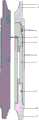
如图1所示,本实施例提供的一种新型扭力减力增力减震钻井工具,包括:As shown in Figure 1, a new type of torsion reduction force increase force shock absorption drilling tool provided by this embodiment includes:
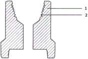
1、上接头1,上端母扣2连接钻铤或钻杆的公扣,现场安装、操作简单;与现有的上扣、卸扣设备完全匹配,互通使用,上扣动力上到行业标准的最优动力值。1. The
所述上接头1,工具的内径与通用的钻杆与钻铤的内径一致。The
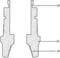
2、下接头13,下端母扣14连接钻头的公扣,现场安装、操作简单的优点;与现有的上扣、卸扣设备完全匹配,互通使用,上扣动力上到行业标准的最优动力值。2. The lower joint 13 and the lower
所述下接头13,工具的内径与通用的钻杆与钻铤的内径一致。The inner diameter of the lower joint 13 is consistent with that of common drill pipes and drill collars.
3、本发明的上接头1从钻杆与钻铤输入钻压、动力、动能,通过上端卡盘5,中间滚轴轴承4,直杆弹簧7,中心轴8,将输入钻压、动力、动能传递到下接头13,最后传递输出钻压、扭力、机械能到钻头。3. The
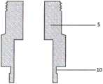
4、本发明的上端卡盘5的上端外圆设置有密封段,密封件3与上端卡盘5密封;上端卡盘5的上端台阶凹起部位与外套筒6的台阶凸起部位互相配合连接,上端卡盘5与外套筒6可以互相转动;上端卡盘5的下端设有柱状槽锁结构母扣端10;与直杆弹簧7上端的柱状槽锁结构公扣端11匹配活动连接。4. The outer circle of the upper end of the
5、本发明的直杆弹簧7:由柱状槽锁结构公扣端11,直杆弹簧7的本体,柱状槽锁结构公扣端11组成。直杆弹簧7的本体为圆柱体结构。直杆弹簧7起到扭力的减力或增力并将吸收动能转换、存储为直杆弹簧7的弹性势能的作用;直杆弹簧7的弹力还起到弹性缓冲切削岩石的作用;动力、动能经转换、存储为弹力、机械能后,在传递给下接头13,输出的弹力、机械能到钻头,完成一次扭力的减力或增力切削岩石的过程。5. The
6、本发明的直杆弹簧7,受钻杆、钻铤的动力作用,当切削岩石的阻力小于或等于直杆弹簧7的最大额定扭转方向弹力值时,钻头依靠直杆弹簧7的扭力的减力或增力的弹力切削岩石阻力的过程。6. The
7、本发明的直杆弹簧7,受钻杆、钻铤的钻压、动力作用,当切削岩石的阻力大于直杆弹簧7的最大额定扭转方向弹力值后,水平扭转方向弹力积聚的弹力、弹性势能,加上钻杆与钻铤的动力、动能共同发挥作用。直杆弹簧7的扭转方向弹力和钻杆与钻铤的动力叠加后形成合力;直杆弹簧7弹性势能和钻杆与钻铤的动能叠加后形成的机械能,共同完成切削岩石。7. The
8、本发明的一种新型扭力减力增力减震钻井工具,连接在钻杆、钻铤与钻头中间位置,一起下入井中实现扭力的减力或增力减震钻井。8. A new type of torque-reducing, force-increasing, and shock-absorbing drilling tool of the present invention is connected at the middle position of the drill pipe, drill collar and drill bit, and is lowered into the well together to realize torsion force-reducing or force-increasing shock-absorbing drilling.
9、本发明的一种新型扭力减力增力减震钻井工具,吸收了过去多年积累的经验,采用“持续吸收动力--转换储存为弹力--弹力瞬间释放叠加动力形成合力”;采用“持续吸收动能--转换储存为弹性势能--弹性势能瞬间释放叠加动能形成机械能”的切削岩石的新设计理念,创新改造发明后应用到石油钻井行业,起到钻井扭力的减力或增力、减震提速的效果,从而提高钻井效率,降低作业成本的目的。9. A new type of torsion reduction force increase force shock absorption drilling tool of the present invention has absorbed the experience accumulated in the past many years, and adopts "continuous absorption of power-conversion and storage into elastic force-instant release of elastic force and superposition of power to form a resultant force"; Continuous absorption of kinetic energy—conversion and storage into elastic potential energy—instantaneous release of elastic potential energy and superposition of kinetic energy to form mechanical energy” is a new design concept for cutting rocks. After innovation, transformation and invention, it is applied to the oil drilling industry to reduce or increase drilling torque. The effect of shock absorption and speed increase, thereby improving drilling efficiency and reducing operating costs.
相较于现有技术,本发明提供的一种新型扭力减力增力减震钻井工具,具有如下优点:Compared with the prior art, the present invention provides a new type of torsion-reducing force-increasing force-absorbing drilling tool, which has the following advantages:
1、一种新型扭力减力增力减震钻井工具,受钻铤与钻杆的动力的作用,当动力小于或等于直杆弹簧7的最大额定扭转方向弹力值时,依靠扭力的减力或增力切削岩石。直杆弹簧7将钻铤与钻杆的动力传递到下接头13,再传递输出到钻头,依靠扭力的减力或增力完成切削岩石。1. A new type of torsion-reducing, force-increasing, shock-absorbing drilling tool is affected by the power of the drill collar and the drill pipe. When the power is less than or equal to the maximum rated elastic force value in the torsional direction of the
2、一种新型扭力减力增力减震钻井工具,受钻铤与钻杆的动力的作用,当动力大于直杆弹簧7的最大额定扭转方向弹力值后,依靠直杆弹簧7的水平扭转方向弹力,叠加钻杆与钻铤的动力,共同产生的合力,传递到下接头13,再传递输出到钻头,依靠扭力的减力或增力完成切削岩石。2. A new type of torsion-reducing force-increasing force-absorbing drilling tool is affected by the power of the drill collar and the drill pipe. When the power is greater than the maximum rated elastic value of the
3、一种新型扭力减力增力减震钻井工具,本发明的直杆弹簧7,受钻杆、钻铤的动力作用,当切削岩石的阻力大于直杆弹簧7的最大额定扭转方向弹力值后,积聚的弹性势能,加上钻杆与钻铤的动能共同发挥作用。直杆弹簧7的扭转方向弹性势能和钻杆与钻铤的动能叠加后形成机械能;依靠直杆弹簧7弹性势能和钻杆与钻铤的动能叠加后形成机械能,完成切削岩石。3. A new type of torsion-reducing, force-increasing, shock-absorbing drilling tool. The
4、一种新型扭力减力增力减震钻井工具,利用了直杆弹簧7只能在一定的旋转角度范围内反复周期性接受钻杆与钻铤提供的动力及切削岩石的反弹力的作用。直杆弹簧7只能水平扭转方向运动,重复积蓄弹力,释放弹力;然后又积蓄弹力,又释放弹力的循环往复特点。4. A new type of torsion-reducing force-increasing force-shock-absorbing drilling tool, which uses the
5、一种新型扭力减力增力减震钻井工具,利用了上接头1,上端卡盘5,通过滚轴轴承4在旋转运动过程中,起到减少滚动摩擦阻力的作用;同时,在旋转运动过程中承受轴向负荷,将垂直方向钻杆与钻铤的钻压,由中心轴8,刚性传递到下接头13,再将垂直方向的钻压传递输出到钻头。5. A new type of torsion reduction force increase force shock absorption drilling tool, which uses the
本发明的工作原理如下:The working principle of the present invention is as follows:
本发明的一种新型扭力减力增力减震钻井工具与钻杆与钻铤一起下入井中,地面钻机输入的动力、动能通过钻杆与钻铤输入到上接头1。A new type of torsion-reducing, force-increasing, shock-absorbing drilling tool of the present invention is lowered into a well together with a drill pipe and a drill collar.
通过上接头1,上端卡盘5,再由上端卡盘5的柱状槽锁结构母扣端10,将动力、动能传递到直杆弹簧7的柱状槽锁结构公扣端11,直杆弹簧7在弹性约束下在一定的旋转角度范围内旋转,直杆弹簧7采用“持续吸收动力--转换储存为弹力--弹力瞬间释放叠加动力形成合力”;采用“持续吸收动能--转换储存为弹性势能--弹性势能瞬间释放叠加动能形成机械能”的转换;通过直杆弹簧7的柱状槽锁结构公扣端11将动力、动能传递到下接头13,最后将动力、动能传递输出到钻头,完成扭力的减力或增力破岩。Through the
动力、动能通过滚轴轴承4的旋转滚动垂直传递,通过中心轴8,及下接头13的垂直刚性传递,最后将钻杆与钻铤输入的压力、钻压传递输出到钻头。The power and kinetic energy are transmitted vertically through the rotation and rolling of the
受钻铤与钻杆的动力的作用,当动力小于或等于直杆弹簧7的最大额定扭转方向弹力值时,依靠扭力减力增力切削岩石。直杆弹簧7将钻铤与钻杆的动力传递到下接头13,再传递输出到钻头,依靠扭力的减力或增力完成切削岩石。Affected by the power of the drill collar and the drill pipe, when the power is less than or equal to the maximum rated elastic force in the torsional direction of the
受钻铤与钻杆的动力的作用,当动力大于直杆弹簧7的最大额定扭转方向弹力值后,依靠直杆弹簧7的水平扭转方向弹力,叠加钻杆与钻铤的动力,共同产生的合力,传递到下接头13,再传递输出到钻头,依靠共同的合力完成切削岩石。Affected by the power of the drill collar and the drill pipe, when the power is greater than the maximum rated elastic value in the torsional direction of the
钻头完成一次切削岩石的过程,是一次“持续吸收动力--转换储存为弹力--弹力瞬间释放叠加动力形成合力”的过程,也是一次“持续吸收动能--转换储存为弹性势能--弹性势能瞬间释放叠加动能形成机械能”的过程,再传递输出动力、动能到钻头,完成一次又一次切削岩石的过程。The process of the drill bit cutting rock is a process of "continuous absorption of power - conversion and storage into elastic force - instant release of elastic force and superposition of power to form a resultant force", and also a process of "continuous absorption of kinetic energy - conversion and storage into elastic potential energy - elastic potential energy The process of instantly releasing superimposed kinetic energy to form mechanical energy, and then transmitting the output power and kinetic energy to the drill bit to complete the process of cutting rocks again and again.
钻头利用扭力减力增力减震,可分为两个阶段。The drill bit utilizes torsional force reduction to increase force and shock absorption, which can be divided into two stages.
第一个阶段钻头依靠扭力的减力或增力、减震:直杆弹簧7,受钻杆、钻铤的动力作用,当切削岩石的阻力小于或等于直杆弹簧7的最大额定扭转方向弹力值时,钻头依靠直杆弹簧7的扭力的减力或增力的弹力切削岩石的过程。In the first stage, the drill bit relies on torsion force reduction or force increase, shock absorption: the
第二个阶段钻头依靠水平扭转方向弹力,叠加钻杆与钻铤的动力产生的合力共同完成减震:当切削岩石的阻力大于直杆弹簧7的最大额定扭转方向弹力值后,直杆弹簧7的扭转方向弹力与钻杆与钻铤的动力叠加后形成合力;直杆弹簧7弹性势能与钻杆与钻铤的动能叠加后共同的机械能,共同完成弹力缓冲减震切削岩石的过程。In the second stage, the drill bit relies on the elastic force in the horizontal torsional direction, and the resultant force generated by superimposing the power of the drill pipe and the drill collar together completes shock absorption: when the resistance of cutting rock is greater than the maximum rated elastic force in the torsional direction of the
本发明的一种新型扭力减力增力减震钻井工具,大大地提高了钻井速度,节省了钻井作业费用,保证对石油,天然气、煤层气或页岩气岩石的钻井提速与安全作业起到关键的提升作用。A new type of torsion-force-reduced-force-force-force-shock-absorbing drilling tool of the present invention greatly increases the drilling speed, saves the cost of drilling operations, and ensures the speed-up and safe operation of oil, natural gas, coalbed methane or shale gas rock drilling. key lifting effect.
最后应说明的是:以上各实施例仅用以说明本发明的技术方案,而非对其限制;尽管参照前述各实施例对本发明进行了详细的说明,本领域的普通技术人员应当理解:其依然可以对前述各实施例所记载的技术方案进行修改,或者对其中部分或者全部技术特征进行等同替换;而这些修改或者替换,并不使相应技术方案的本质脱离本发明各实施例技术方案的范围。Finally, it should be noted that: the above embodiments are only used to illustrate the technical solutions of the present invention, rather than limiting them; although the present invention has been described in detail with reference to the foregoing embodiments, those of ordinary skill in the art should understand that: It is still possible to modify the technical solutions described in the foregoing embodiments, or perform equivalent replacements for some or all of the technical features; and these modifications or replacements do not make the essence of the corresponding technical solutions deviate from the technical solutions of the various embodiments of the present invention. scope.
Claims (9)
Priority Applications (1)
| Application Number | Priority Date | Filing Date | Title |
|---|---|---|---|
| CN202111139607.4ACN115874955A (en) | 2021-09-28 | 2021-09-28 | A new type of torsion reduction force increase force shock absorption drilling tool |
Applications Claiming Priority (1)
| Application Number | Priority Date | Filing Date | Title |
|---|---|---|---|
| CN202111139607.4ACN115874955A (en) | 2021-09-28 | 2021-09-28 | A new type of torsion reduction force increase force shock absorption drilling tool |
Publications (1)
| Publication Number | Publication Date |
|---|---|
| CN115874955Atrue CN115874955A (en) | 2023-03-31 |
Family
ID=85763188
Family Applications (1)
| Application Number | Title | Priority Date | Filing Date |
|---|---|---|---|
| CN202111139607.4APendingCN115874955A (en) | 2021-09-28 | 2021-09-28 | A new type of torsion reduction force increase force shock absorption drilling tool |
Country Status (1)
| Country | Link |
|---|---|
| CN (1) | CN115874955A (en) |
Citations (9)
| Publication number | Priority date | Publication date | Assignee | Title |
|---|---|---|---|---|
| US3947008A (en)* | 1974-12-23 | 1976-03-30 | Schlumberger Technology Corporation | Drill string shock absorber |
| US20110198126A1 (en)* | 2007-09-04 | 2011-08-18 | George Swietlik | Downhole device |
| CN105298384A (en)* | 2015-09-24 | 2016-02-03 | 四川飞翔能源有限公司 | Continuous drilling machine |
| CN106639910A (en)* | 2016-11-15 | 2017-05-10 | 常州大学 | Multi-stage damping device for drill stem |
| CN108487856A (en)* | 2018-05-23 | 2018-09-04 | 成都奥尤盖茨科技发展有限公司 | A kind of flexible pressurizing torsion generator |
| CN108643838A (en)* | 2018-03-29 | 2018-10-12 | 西南石油大学 | A kind of adjustable guide drilling tool in underground |
| CN109750977A (en)* | 2017-11-01 | 2019-05-14 | 陈晓新 | A new type of drilling torque-increasing defibrillation and vibration-eliminating tool |
| CN110685612A (en)* | 2018-07-04 | 2020-01-14 | 陈玥丹 | Horizontal torsional elastic buffering and impact rock breaking drilling tool |
| CN111764841A (en)* | 2019-04-02 | 2020-10-13 | 陈晓新 | A new type of horizontal torsional elastic buffer cutting rock-breaking drilling tool |
- 2021
- 2021-09-28CNCN202111139607.4Apatent/CN115874955A/enactivePending
Patent Citations (9)
| Publication number | Priority date | Publication date | Assignee | Title |
|---|---|---|---|---|
| US3947008A (en)* | 1974-12-23 | 1976-03-30 | Schlumberger Technology Corporation | Drill string shock absorber |
| US20110198126A1 (en)* | 2007-09-04 | 2011-08-18 | George Swietlik | Downhole device |
| CN105298384A (en)* | 2015-09-24 | 2016-02-03 | 四川飞翔能源有限公司 | Continuous drilling machine |
| CN106639910A (en)* | 2016-11-15 | 2017-05-10 | 常州大学 | Multi-stage damping device for drill stem |
| CN109750977A (en)* | 2017-11-01 | 2019-05-14 | 陈晓新 | A new type of drilling torque-increasing defibrillation and vibration-eliminating tool |
| CN108643838A (en)* | 2018-03-29 | 2018-10-12 | 西南石油大学 | A kind of adjustable guide drilling tool in underground |
| CN108487856A (en)* | 2018-05-23 | 2018-09-04 | 成都奥尤盖茨科技发展有限公司 | A kind of flexible pressurizing torsion generator |
| CN110685612A (en)* | 2018-07-04 | 2020-01-14 | 陈玥丹 | Horizontal torsional elastic buffering and impact rock breaking drilling tool |
| CN111764841A (en)* | 2019-04-02 | 2020-10-13 | 陈晓新 | A new type of horizontal torsional elastic buffer cutting rock-breaking drilling tool |
Similar Documents
| Publication | Publication Date | Title |
|---|---|---|
| CN207194873U (en) | A kind of high-strength shock absorber | |
| CN110685612A (en) | Horizontal torsional elastic buffering and impact rock breaking drilling tool | |
| CN203430420U (en) | Novel torque percussion drilling tool | |
| CN106639943A (en) | High-frequency torsion-restoration axial vibration impacting tool | |
| CN103883246A (en) | Efficient positive displacement motor drill under well | |
| CN206801458U (en) | The axial impact instrument of speed changing function can be realized based on flexible tooth | |
| CN115874955A (en) | A new type of torsion reduction force increase force shock absorption drilling tool | |
| CN101979818B (en) | Hydraulic reshaper | |
| CN108661550A (en) | One-way fashion impactor based on turbine and spring | |
| CN201087695Y (en) | High wind pressure downhole air hammer | |
| CN111764841A (en) | A new type of horizontal torsional elastic buffer cutting rock-breaking drilling tool | |
| CN201144637Y (en) | Power head with shock-absorbing device | |
| CN115217418B (en) | Full-dimensional antifriction and resistance-reducing oscillator | |
| CN104963639A (en) | Underground torque control tool for milling operation | |
| CN203716838U (en) | Rotor power head with buffer device | |
| CN202273635U (en) | Climbing type reducing blowout preventer | |
| CN205778593U (en) | A kind of anti-galling drilling tool thread joint | |
| CN109750977A (en) | A new type of drilling torque-increasing defibrillation and vibration-eliminating tool | |
| CN205977090U (en) | High -efficient anti screw rod drilling tool that dashes | |
| CN204627871U (en) | A kind of welding valve piston buffering sea wind generator | |
| CN201184156Y (en) | Variable radial expanding head for expansion reinforcing | |
| CN201851037U (en) | Cushioning device | |
| CN208473732U (en) | A kind of structure for preventing damper screw thread to be buckled to | |
| CN202152635U (en) | A Drill String Axial Oscillation Tool | |
| CN106122385A (en) | A kind of twist bit |
Legal Events
| Date | Code | Title | Description |
|---|---|---|---|
| PB01 | Publication | ||
| PB01 | Publication | ||
| SE01 | Entry into force of request for substantive examination | ||
| SE01 | Entry into force of request for substantive examination |