CN115868975A - Compact Analyte Detection Devices - Google Patents
Compact Analyte Detection DevicesDownload PDFInfo
- Publication number
- CN115868975A CN115868975ACN202210110638.5ACN202210110638ACN115868975ACN 115868975 ACN115868975 ACN 115868975ACN 202210110638 ACN202210110638 ACN 202210110638ACN 115868975 ACN115868975 ACN 115868975A
- Authority
- CN
- China
- Prior art keywords
- detection device
- analyte detection
- circuit board
- compact
- sensor
- Prior art date
- Legal status (The legal status is an assumption and is not a legal conclusion. Google has not performed a legal analysis and makes no representation as to the accuracy of the status listed.)
- Pending
Links
Images


Classifications
- H—ELECTRICITY
- H01—ELECTRIC ELEMENTS
- H01Q—ANTENNAS, i.e. RADIO AERIALS
- H01Q1/00—Details of, or arrangements associated with, antennas
- H01Q1/36—Structural form of radiating elements, e.g. cone, spiral, umbrella; Particular materials used therewith
- A—HUMAN NECESSITIES
- A61—MEDICAL OR VETERINARY SCIENCE; HYGIENE
- A61B—DIAGNOSIS; SURGERY; IDENTIFICATION
- A61B5/00—Measuring for diagnostic purposes; Identification of persons
- A61B5/145—Measuring characteristics of blood in vivo, e.g. gas concentration or pH-value ; Measuring characteristics of body fluids or tissues, e.g. interstitial fluid or cerebral tissue
- A61B5/1455—Measuring characteristics of blood in vivo, e.g. gas concentration or pH-value ; Measuring characteristics of body fluids or tissues, e.g. interstitial fluid or cerebral tissue using optical sensors, e.g. spectral photometrical oximeters
- A61B5/1459—Measuring characteristics of blood in vivo, e.g. gas concentration or pH-value ; Measuring characteristics of body fluids or tissues, e.g. interstitial fluid or cerebral tissue using optical sensors, e.g. spectral photometrical oximeters invasive, e.g. introduced into the body by a catheter
- A—HUMAN NECESSITIES
- A61—MEDICAL OR VETERINARY SCIENCE; HYGIENE
- A61B—DIAGNOSIS; SURGERY; IDENTIFICATION
- A61B5/00—Measuring for diagnostic purposes; Identification of persons
- A61B5/145—Measuring characteristics of blood in vivo, e.g. gas concentration or pH-value ; Measuring characteristics of body fluids or tissues, e.g. interstitial fluid or cerebral tissue
- A61B5/14532—Measuring characteristics of blood in vivo, e.g. gas concentration or pH-value ; Measuring characteristics of body fluids or tissues, e.g. interstitial fluid or cerebral tissue for measuring glucose, e.g. by tissue impedance measurement
- A—HUMAN NECESSITIES
- A61—MEDICAL OR VETERINARY SCIENCE; HYGIENE
- A61B—DIAGNOSIS; SURGERY; IDENTIFICATION
- A61B5/00—Measuring for diagnostic purposes; Identification of persons
- A61B5/0002—Remote monitoring of patients using telemetry, e.g. transmission of vital signals via a communication network
- A—HUMAN NECESSITIES
- A61—MEDICAL OR VETERINARY SCIENCE; HYGIENE
- A61B—DIAGNOSIS; SURGERY; IDENTIFICATION
- A61B5/00—Measuring for diagnostic purposes; Identification of persons
- A61B5/145—Measuring characteristics of blood in vivo, e.g. gas concentration or pH-value ; Measuring characteristics of body fluids or tissues, e.g. interstitial fluid or cerebral tissue
- A61B5/14503—Measuring characteristics of blood in vivo, e.g. gas concentration or pH-value ; Measuring characteristics of body fluids or tissues, e.g. interstitial fluid or cerebral tissue invasive, e.g. introduced into the body by a catheter or needle or using implanted sensors
- A—HUMAN NECESSITIES
- A61—MEDICAL OR VETERINARY SCIENCE; HYGIENE
- A61B—DIAGNOSIS; SURGERY; IDENTIFICATION
- A61B5/00—Measuring for diagnostic purposes; Identification of persons
- A61B5/145—Measuring characteristics of blood in vivo, e.g. gas concentration or pH-value ; Measuring characteristics of body fluids or tissues, e.g. interstitial fluid or cerebral tissue
- A61B5/14546—Measuring characteristics of blood in vivo, e.g. gas concentration or pH-value ; Measuring characteristics of body fluids or tissues, e.g. interstitial fluid or cerebral tissue for measuring analytes not otherwise provided for, e.g. ions, cytochromes
- A—HUMAN NECESSITIES
- A61—MEDICAL OR VETERINARY SCIENCE; HYGIENE
- A61B—DIAGNOSIS; SURGERY; IDENTIFICATION
- A61B5/00—Measuring for diagnostic purposes; Identification of persons
- A61B5/145—Measuring characteristics of blood in vivo, e.g. gas concentration or pH-value ; Measuring characteristics of body fluids or tissues, e.g. interstitial fluid or cerebral tissue
- A61B5/1468—Measuring characteristics of blood in vivo, e.g. gas concentration or pH-value ; Measuring characteristics of body fluids or tissues, e.g. interstitial fluid or cerebral tissue using chemical or electrochemical methods, e.g. by polarographic means
- A61B5/1473—Measuring characteristics of blood in vivo, e.g. gas concentration or pH-value ; Measuring characteristics of body fluids or tissues, e.g. interstitial fluid or cerebral tissue using chemical or electrochemical methods, e.g. by polarographic means invasive, e.g. introduced into the body by a catheter
- A—HUMAN NECESSITIES
- A61—MEDICAL OR VETERINARY SCIENCE; HYGIENE
- A61B—DIAGNOSIS; SURGERY; IDENTIFICATION
- A61B5/00—Measuring for diagnostic purposes; Identification of persons
- A61B5/145—Measuring characteristics of blood in vivo, e.g. gas concentration or pH-value ; Measuring characteristics of body fluids or tissues, e.g. interstitial fluid or cerebral tissue
- A61B5/1468—Measuring characteristics of blood in vivo, e.g. gas concentration or pH-value ; Measuring characteristics of body fluids or tissues, e.g. interstitial fluid or cerebral tissue using chemical or electrochemical methods, e.g. by polarographic means
- A61B5/1486—Measuring characteristics of blood in vivo, e.g. gas concentration or pH-value ; Measuring characteristics of body fluids or tissues, e.g. interstitial fluid or cerebral tissue using chemical or electrochemical methods, e.g. by polarographic means using enzyme electrodes, e.g. with immobilised oxidase
- A61B5/14865—Measuring characteristics of blood in vivo, e.g. gas concentration or pH-value ; Measuring characteristics of body fluids or tissues, e.g. interstitial fluid or cerebral tissue using chemical or electrochemical methods, e.g. by polarographic means using enzyme electrodes, e.g. with immobilised oxidase invasive, e.g. introduced into the body by a catheter or needle or using implanted sensors
- A—HUMAN NECESSITIES
- A61—MEDICAL OR VETERINARY SCIENCE; HYGIENE
- A61B—DIAGNOSIS; SURGERY; IDENTIFICATION
- A61B5/00—Measuring for diagnostic purposes; Identification of persons
- A61B5/145—Measuring characteristics of blood in vivo, e.g. gas concentration or pH-value ; Measuring characteristics of body fluids or tissues, e.g. interstitial fluid or cerebral tissue
- A61B5/1495—Calibrating or testing of in-vivo probes
- A—HUMAN NECESSITIES
- A61—MEDICAL OR VETERINARY SCIENCE; HYGIENE
- A61B—DIAGNOSIS; SURGERY; IDENTIFICATION
- A61B5/00—Measuring for diagnostic purposes; Identification of persons
- A61B5/68—Arrangements of detecting, measuring or recording means, e.g. sensors, in relation to patient
- A61B5/6801—Arrangements of detecting, measuring or recording means, e.g. sensors, in relation to patient specially adapted to be attached to or worn on the body surface
- A61B5/683—Means for maintaining contact with the body
- A61B5/6835—Supports or holders, e.g., articulated arms
- A—HUMAN NECESSITIES
- A61—MEDICAL OR VETERINARY SCIENCE; HYGIENE
- A61B—DIAGNOSIS; SURGERY; IDENTIFICATION
- A61B5/00—Measuring for diagnostic purposes; Identification of persons
- A61B5/68—Arrangements of detecting, measuring or recording means, e.g. sensors, in relation to patient
- A61B5/6846—Arrangements of detecting, measuring or recording means, e.g. sensors, in relation to patient specially adapted to be brought in contact with an internal body part, i.e. invasive
- A61B5/6847—Arrangements of detecting, measuring or recording means, e.g. sensors, in relation to patient specially adapted to be brought in contact with an internal body part, i.e. invasive mounted on an invasive device
- A61B5/6848—Needles
- A61B5/6849—Needles in combination with a needle set
- A—HUMAN NECESSITIES
- A61—MEDICAL OR VETERINARY SCIENCE; HYGIENE
- A61B—DIAGNOSIS; SURGERY; IDENTIFICATION
- A61B5/00—Measuring for diagnostic purposes; Identification of persons
- A61B5/72—Signal processing specially adapted for physiological signals or for diagnostic purposes
- A61B5/7235—Details of waveform analysis
- A61B5/7264—Classification of physiological signals or data, e.g. using neural networks, statistical classifiers, expert systems or fuzzy systems
- A—HUMAN NECESSITIES
- A61—MEDICAL OR VETERINARY SCIENCE; HYGIENE
- A61B—DIAGNOSIS; SURGERY; IDENTIFICATION
- A61B5/00—Measuring for diagnostic purposes; Identification of persons
- A61B5/74—Details of notification to user or communication with user or patient; User input means
- A61B5/7405—Details of notification to user or communication with user or patient; User input means using sound
- A—HUMAN NECESSITIES
- A61—MEDICAL OR VETERINARY SCIENCE; HYGIENE
- A61B—DIAGNOSIS; SURGERY; IDENTIFICATION
- A61B5/00—Measuring for diagnostic purposes; Identification of persons
- A61B5/74—Details of notification to user or communication with user or patient; User input means
- A61B5/742—Details of notification to user or communication with user or patient; User input means using visual displays
- A—HUMAN NECESSITIES
- A61—MEDICAL OR VETERINARY SCIENCE; HYGIENE
- A61B—DIAGNOSIS; SURGERY; IDENTIFICATION
- A61B5/00—Measuring for diagnostic purposes; Identification of persons
- A61B5/74—Details of notification to user or communication with user or patient; User input means
- A61B5/7455—Details of notification to user or communication with user or patient; User input means characterised by tactile indication, e.g. vibration or electrical stimulation
- A—HUMAN NECESSITIES
- A61—MEDICAL OR VETERINARY SCIENCE; HYGIENE
- A61B—DIAGNOSIS; SURGERY; IDENTIFICATION
- A61B5/00—Measuring for diagnostic purposes; Identification of persons
- A61B5/74—Details of notification to user or communication with user or patient; User input means
- A61B5/746—Alarms related to a physiological condition, e.g. details of setting alarm thresholds or avoiding false alarms
- B—PERFORMING OPERATIONS; TRANSPORTING
- B01—PHYSICAL OR CHEMICAL PROCESSES OR APPARATUS IN GENERAL
- B01L—CHEMICAL OR PHYSICAL LABORATORY APPARATUS FOR GENERAL USE
- B01L3/00—Containers or dishes for laboratory use, e.g. laboratory glassware; Droppers
- B01L3/50—Containers for the purpose of retaining a material to be analysed, e.g. test tubes
- B01L3/502—Containers for the purpose of retaining a material to be analysed, e.g. test tubes with fluid transport, e.g. in multi-compartment structures
- B01L3/5027—Containers for the purpose of retaining a material to be analysed, e.g. test tubes with fluid transport, e.g. in multi-compartment structures by integrated microfluidic structures, i.e. dimensions of channels and chambers are such that surface tension forces are important, e.g. lab-on-a-chip
- B01L3/502715—Containers for the purpose of retaining a material to be analysed, e.g. test tubes with fluid transport, e.g. in multi-compartment structures by integrated microfluidic structures, i.e. dimensions of channels and chambers are such that surface tension forces are important, e.g. lab-on-a-chip characterised by interfacing components, e.g. fluidic, electrical, optical or mechanical interfaces
- C—CHEMISTRY; METALLURGY
- C12—BIOCHEMISTRY; BEER; SPIRITS; WINE; VINEGAR; MICROBIOLOGY; ENZYMOLOGY; MUTATION OR GENETIC ENGINEERING
- C12Q—MEASURING OR TESTING PROCESSES INVOLVING ENZYMES, NUCLEIC ACIDS OR MICROORGANISMS; COMPOSITIONS OR TEST PAPERS THEREFOR; PROCESSES OF PREPARING SUCH COMPOSITIONS; CONDITION-RESPONSIVE CONTROL IN MICROBIOLOGICAL OR ENZYMOLOGICAL PROCESSES
- C12Q1/00—Measuring or testing processes involving enzymes, nucleic acids or microorganisms; Compositions therefor; Processes of preparing such compositions
- C12Q1/001—Enzyme electrodes
- C12Q1/005—Enzyme electrodes involving specific analytes or enzymes
- C12Q1/006—Enzyme electrodes involving specific analytes or enzymes for glucose
- G—PHYSICS
- G16—INFORMATION AND COMMUNICATION TECHNOLOGY [ICT] SPECIALLY ADAPTED FOR SPECIFIC APPLICATION FIELDS
- G16H—HEALTHCARE INFORMATICS, i.e. INFORMATION AND COMMUNICATION TECHNOLOGY [ICT] SPECIALLY ADAPTED FOR THE HANDLING OR PROCESSING OF MEDICAL OR HEALTHCARE DATA
- G16H40/00—ICT specially adapted for the management or administration of healthcare resources or facilities; ICT specially adapted for the management or operation of medical equipment or devices
- G16H40/60—ICT specially adapted for the management or administration of healthcare resources or facilities; ICT specially adapted for the management or operation of medical equipment or devices for the operation of medical equipment or devices
- G16H40/67—ICT specially adapted for the management or administration of healthcare resources or facilities; ICT specially adapted for the management or operation of medical equipment or devices for the operation of medical equipment or devices for remote operation
- H—ELECTRICITY
- H01—ELECTRIC ELEMENTS
- H01Q—ANTENNAS, i.e. RADIO AERIALS
- H01Q1/00—Details of, or arrangements associated with, antennas
- H01Q1/12—Supports; Mounting means
- H01Q1/22—Supports; Mounting means by structural association with other equipment or articles
- H01Q1/24—Supports; Mounting means by structural association with other equipment or articles with receiving set
- A—HUMAN NECESSITIES
- A61—MEDICAL OR VETERINARY SCIENCE; HYGIENE
- A61B—DIAGNOSIS; SURGERY; IDENTIFICATION
- A61B2560/00—Constructional details of operational features of apparatus; Accessories for medical measuring apparatus
- A61B2560/02—Operational features
- A61B2560/0204—Operational features of power management
- A61B2560/0209—Operational features of power management adapted for power saving
- A—HUMAN NECESSITIES
- A61—MEDICAL OR VETERINARY SCIENCE; HYGIENE
- A61B—DIAGNOSIS; SURGERY; IDENTIFICATION
- A61B2560/00—Constructional details of operational features of apparatus; Accessories for medical measuring apparatus
- A61B2560/02—Operational features
- A61B2560/0204—Operational features of power management
- A61B2560/0214—Operational features of power management of power generation or supply
- A—HUMAN NECESSITIES
- A61—MEDICAL OR VETERINARY SCIENCE; HYGIENE
- A61B—DIAGNOSIS; SURGERY; IDENTIFICATION
- A61B2560/00—Constructional details of operational features of apparatus; Accessories for medical measuring apparatus
- A61B2560/02—Operational features
- A61B2560/0223—Operational features of calibration, e.g. protocols for calibrating sensors
- A61B2560/0228—Operational features of calibration, e.g. protocols for calibrating sensors using calibration standards
- A—HUMAN NECESSITIES
- A61—MEDICAL OR VETERINARY SCIENCE; HYGIENE
- A61B—DIAGNOSIS; SURGERY; IDENTIFICATION
- A61B2560/00—Constructional details of operational features of apparatus; Accessories for medical measuring apparatus
- A61B2560/02—Operational features
- A61B2560/0223—Operational features of calibration, e.g. protocols for calibrating sensors
- A61B2560/0238—Means for recording calibration data
- A—HUMAN NECESSITIES
- A61—MEDICAL OR VETERINARY SCIENCE; HYGIENE
- A61B—DIAGNOSIS; SURGERY; IDENTIFICATION
- A61B2560/00—Constructional details of operational features of apparatus; Accessories for medical measuring apparatus
- A61B2560/04—Constructional details of apparatus
- A61B2560/0443—Modular apparatus
- A61B2560/045—Modular apparatus with a separable interface unit, e.g. for communication
- A—HUMAN NECESSITIES
- A61—MEDICAL OR VETERINARY SCIENCE; HYGIENE
- A61B—DIAGNOSIS; SURGERY; IDENTIFICATION
- A61B2560/00—Constructional details of operational features of apparatus; Accessories for medical measuring apparatus
- A61B2560/04—Constructional details of apparatus
- A61B2560/0462—Apparatus with built-in sensors
- B—PERFORMING OPERATIONS; TRANSPORTING
- B01—PHYSICAL OR CHEMICAL PROCESSES OR APPARATUS IN GENERAL
- B01L—CHEMICAL OR PHYSICAL LABORATORY APPARATUS FOR GENERAL USE
- B01L2200/00—Solutions for specific problems relating to chemical or physical laboratory apparatus
- B01L2200/06—Fluid handling related problems
- B01L2200/0689—Sealing
- B—PERFORMING OPERATIONS; TRANSPORTING
- B01—PHYSICAL OR CHEMICAL PROCESSES OR APPARATUS IN GENERAL
- B01L—CHEMICAL OR PHYSICAL LABORATORY APPARATUS FOR GENERAL USE
- B01L2300/00—Additional constructional details
- B01L2300/02—Identification, exchange or storage of information
- B01L2300/023—Sending and receiving of information, e.g. using bluetooth
- B—PERFORMING OPERATIONS; TRANSPORTING
- B01—PHYSICAL OR CHEMICAL PROCESSES OR APPARATUS IN GENERAL
- B01L—CHEMICAL OR PHYSICAL LABORATORY APPARATUS FOR GENERAL USE
- B01L2300/00—Additional constructional details
- B01L2300/06—Auxiliary integrated devices, integrated components
- B01L2300/0627—Sensor or part of a sensor is integrated
- B01L2300/0645—Electrodes
- B—PERFORMING OPERATIONS; TRANSPORTING
- B01—PHYSICAL OR CHEMICAL PROCESSES OR APPARATUS IN GENERAL
- B01L—CHEMICAL OR PHYSICAL LABORATORY APPARATUS FOR GENERAL USE
- B01L2300/00—Additional constructional details
- B01L2300/08—Geometry, shape and general structure
- B01L2300/0832—Geometry, shape and general structure cylindrical, tube shaped
- B—PERFORMING OPERATIONS; TRANSPORTING
- B01—PHYSICAL OR CHEMICAL PROCESSES OR APPARATUS IN GENERAL
- B01L—CHEMICAL OR PHYSICAL LABORATORY APPARATUS FOR GENERAL USE
- B01L2300/00—Additional constructional details
- B01L2300/08—Geometry, shape and general structure
- B01L2300/0861—Configuration of multiple channels and/or chambers in a single devices
- B01L2300/088—Channel loops
- B—PERFORMING OPERATIONS; TRANSPORTING
- B01—PHYSICAL OR CHEMICAL PROCESSES OR APPARATUS IN GENERAL
- B01L—CHEMICAL OR PHYSICAL LABORATORY APPARATUS FOR GENERAL USE
- B01L2300/00—Additional constructional details
- B01L2300/12—Specific details about materials
- Y—GENERAL TAGGING OF NEW TECHNOLOGICAL DEVELOPMENTS; GENERAL TAGGING OF CROSS-SECTIONAL TECHNOLOGIES SPANNING OVER SEVERAL SECTIONS OF THE IPC; TECHNICAL SUBJECTS COVERED BY FORMER USPC CROSS-REFERENCE ART COLLECTIONS [XRACs] AND DIGESTS
- Y02—TECHNOLOGIES OR APPLICATIONS FOR MITIGATION OR ADAPTATION AGAINST CLIMATE CHANGE
- Y02D—CLIMATE CHANGE MITIGATION TECHNOLOGIES IN INFORMATION AND COMMUNICATION TECHNOLOGIES [ICT], I.E. INFORMATION AND COMMUNICATION TECHNOLOGIES AIMING AT THE REDUCTION OF THEIR OWN ENERGY USE
- Y02D30/00—Reducing energy consumption in communication networks
- Y02D30/70—Reducing energy consumption in communication networks in wireless communication networks
- Y—GENERAL TAGGING OF NEW TECHNOLOGICAL DEVELOPMENTS; GENERAL TAGGING OF CROSS-SECTIONAL TECHNOLOGIES SPANNING OVER SEVERAL SECTIONS OF THE IPC; TECHNICAL SUBJECTS COVERED BY FORMER USPC CROSS-REFERENCE ART COLLECTIONS [XRACs] AND DIGESTS
- Y02—TECHNOLOGIES OR APPLICATIONS FOR MITIGATION OR ADAPTATION AGAINST CLIMATE CHANGE
- Y02E—REDUCTION OF GREENHOUSE GAS [GHG] EMISSIONS, RELATED TO ENERGY GENERATION, TRANSMISSION OR DISTRIBUTION
- Y02E60/00—Enabling technologies; Technologies with a potential or indirect contribution to GHG emissions mitigation
- Y02E60/10—Energy storage using batteries
Landscapes
- Health & Medical Sciences (AREA)
- Life Sciences & Earth Sciences (AREA)
- Physics & Mathematics (AREA)
- Engineering & Computer Science (AREA)
- General Health & Medical Sciences (AREA)
- Biomedical Technology (AREA)
- Biophysics (AREA)
- Medical Informatics (AREA)
- Molecular Biology (AREA)
- Public Health (AREA)
- Heart & Thoracic Surgery (AREA)
- Surgery (AREA)
- Animal Behavior & Ethology (AREA)
- Pathology (AREA)
- Veterinary Medicine (AREA)
- Optics & Photonics (AREA)
- Chemical & Material Sciences (AREA)
- Chemical Kinetics & Catalysis (AREA)
- General Chemical & Material Sciences (AREA)
- Emergency Medicine (AREA)
- Organic Chemistry (AREA)
- Physiology (AREA)
- Artificial Intelligence (AREA)
- Analytical Chemistry (AREA)
- Proteomics, Peptides & Aminoacids (AREA)
- Zoology (AREA)
- Wood Science & Technology (AREA)
- Computer Vision & Pattern Recognition (AREA)
- Evolutionary Computation (AREA)
- Signal Processing (AREA)
- Psychiatry (AREA)
- Mathematical Physics (AREA)
- Fuzzy Systems (AREA)
- Biotechnology (AREA)
- General Business, Economics & Management (AREA)
- Genetics & Genomics (AREA)
- General Engineering & Computer Science (AREA)
- Bioinformatics & Cheminformatics (AREA)
- Primary Health Care (AREA)
- Epidemiology (AREA)
Abstract
Translated fromChinese
Description
Translated fromChinese相关申请的交叉引用Cross References to Related Applications
本申请要求以下专利申请的权益并要求其优先权:2021年9月27日提交的PCT专利申请,申请号为PCT/CN2021/120856。This application claims the benefit of, and claims priority from, the following patent application: PCT patent application filed September 27, 2021 with application number PCT/CN2021/120856.
技术领域technical field
本发明主要涉及医疗器械领域,特别涉及一种紧凑型分析物检测器件。The invention mainly relates to the field of medical devices, in particular to a compact analyte detection device.
背景技术Background technique
正常人身体中的胰腺可自动监测人体血液中的葡萄糖含量,并自动分泌所需的胰岛素/胰高血糖素。而糖尿病患者胰腺的功能出现异常状况,无法正常分泌人体所需胰岛素。因此糖尿病是人体胰腺功能出现异常而导致的代谢类疾病,糖尿病为终身疾病。目前医疗技术尚无法根治糖尿病,只能通过稳定血糖来控制糖尿病及其并发症的发生和发展。The pancreas in a normal human body can automatically monitor the glucose content in the human blood and automatically secrete the required insulin/glucagon. The function of the pancreas in diabetic patients is abnormal and cannot normally secrete the insulin needed by the human body. Therefore, diabetes is a metabolic disease caused by abnormal pancreatic function, and diabetes is a lifelong disease. At present, medical technology is still unable to cure diabetes, and the occurrence and development of diabetes and its complications can only be controlled by stabilizing blood sugar.
糖尿病患者在向体内注射胰岛素之前需要检测血糖。目前多数的检测手段可以对血糖连续检测,并将血糖数据实时发送至远程设备,便于用户查看,这种检测方法称为连续葡萄糖检测(Continuous Glucose Monitoring,CGM)。该方法需要检测装置贴在皮肤表面,将其携带的探头刺入皮下的组织液完成检测。Diabetics need to check their blood sugar before injecting insulin into their body. At present, most detection methods can continuously detect blood glucose, and send blood glucose data to remote devices in real time, which is convenient for users to view. This detection method is called Continuous Glucose Monitoring (CGM). This method requires the detection device to be attached to the skin surface, and the probe carried by it is inserted into the subcutaneous interstitial fluid to complete the detection.
现有技术的分析物检测器件采用纽扣电池供电,电池单独的密封设置在发射器或底壳中,发射器再与底壳进一步卡合形成分析物检测器件,增加了分析物检测器件的结构复杂度,不利于分析物检测器件的小型化发展。The analyte detection device in the prior art is powered by a button battery, and the battery is separately sealed and arranged in the transmitter or the bottom case, and the transmitter is further engaged with the bottom case to form the analyte detection device, which increases the complexity of the structure of the analyte detection device The degree is not conducive to the miniaturization development of analyte detection devices.
因此,现有技术亟需一种结构设计更紧凑的分析物检测器件。Therefore, there is an urgent need for an analyte detection device with a more compact structural design in the prior art.
发明内容Contents of the invention
本发明实施例公开了一种紧凑型分析物检测器件,包括外壳,外壳内设置有电路板,电池和传感器,外壳包括第一外壳体和第二外壳体,电路板,电池和传感器的体外部分都设置第一外壳体、第二外壳体和传感器的体内部分形成的封闭空间中,结构简单,布局紧凑,利于分析物检测器件的小型化发展。The embodiment of the present invention discloses a compact analyte detection device, which includes a housing, a circuit board, a battery and a sensor are arranged inside the housing, and the housing includes a first outer housing and a second outer housing, a circuit board, a battery and an extracorporeal part of the sensor All are arranged in the closed space formed by the first outer casing, the second outer casing and the internal part of the sensor, with simple structure and compact layout, which is beneficial to the miniaturization development of analyte detection devices.
本发明公开了一种紧凑型分析物检测器件,包括:外壳,外壳内设置有电路板、电池和传感器;外壳包括第一外壳体和第二外壳体,在第一外壳体内设置有传感器;传感器包括体内部分和体外部分,体外部分通过电连接件与电路板电连接,体内部分穿过第一外壳体到外部;电路板上设置有发射器天线,用于与外界设备通信。The invention discloses a compact analyte detection device, which comprises: a housing in which a circuit board, a battery and a sensor are arranged; the housing includes a first housing and a second housing, and a sensor is arranged in the first housing; the sensor It includes an internal part and an external part, the external part is electrically connected to the circuit board through an electrical connector, and the internal part passes through the first outer shell to the outside; the circuit board is provided with a transmitter antenna for communicating with external devices.
根据本发明的一个方面,电连接件包括至少两个导电区和至少一个绝缘区,相邻两个导电区之间设置述绝缘区。According to one aspect of the present invention, the electrical connector includes at least two conductive regions and at least one insulating region, and the insulating region is arranged between two adjacent conductive regions.
根据本发明的一个方面,电连接件为固体导电胶。According to one aspect of the present invention, the electrical connector is solid conductive glue.
根据本发明的一个方面,电连接件为弹性导电件。According to one aspect of the present invention, the electrical connector is an elastic conductive member.
根据本发明的一个方面,弹性导电件至少包括压缩弹簧,导电弹片,导电橡胶,导电泡棉,ACF中的一种。According to one aspect of the present invention, the elastic conductive member includes at least one of compression springs, conductive shrapnel, conductive rubber, conductive foam, and ACF.
根据本发明的一个方面,体内部分相对于体外部分弯折。According to one aspect of the invention, the inner body part is bent relative to the outer body part.
根据本发明的一个方面,体外部分平铺在第二外壳体内侧。According to one aspect of the invention, the extracorporeal part is laid flat inside the second outer shell.
根据本发明的一个方面,体外部分固定在第一外壳体内侧。According to one aspect of the invention, the extracorporeal part is secured inside the first outer shell.
根据本发明的一个方面,电池与电路板并排设置在第二外壳体内。According to one aspect of the present invention, the battery and the circuit board are arranged in the second housing side by side.
根据本发明的一个方面,第二外壳体内还设置有固定结构,用于固定电池与电路板。According to one aspect of the present invention, a fixing structure is further arranged inside the second housing for fixing the battery and the circuit board.
根据本发明的一个方面,固定结构包括定位柱和支撑台。According to one aspect of the present invention, the fixing structure includes a positioning column and a supporting platform.
根据本发明的一个方面,电路板的形状与电池形状和壳体形状相适应。According to an aspect of the present invention, the shape of the circuit board is adapted to the shape of the battery and the shape of the case.
根据本发明的一个方面,电路板为柔性电路板。According to one aspect of the present invention, the circuit board is a flexible circuit board.
根据本发明的一个方面,在第一外壳体的外侧设置有粘性贴片,用于粘贴在用户皮肤表面。According to one aspect of the present invention, an adhesive patch is provided on the outer side of the first outer casing for sticking on the user's skin surface.
根据本发明的一个方面,粘性贴片上设置有保护膜,保护膜的洛氏硬度大于粘性贴片。According to one aspect of the present invention, the adhesive patch is provided with a protective film, and the Rockwell hardness of the protective film is greater than that of the adhesive patch.
与现有技术相比,本发明的技术方案具备以下优点:Compared with the prior art, the technical solution of the present invention has the following advantages:
本发明公开的紧凑型分析物检测器件中,包括外壳,外壳内设置有电路板,电池和传感器,外壳包括第一外壳体和第二外壳体,电路板,电池和传感器的体外部分都设置第一外壳体、第二外壳体和传感器的体内部分形成的封闭空间中,结构简单,布局紧凑,利于分析物检测器件的小型化发展。The compact analyte detection device disclosed in the present invention includes a casing, a circuit board, a battery and a sensor are arranged inside the casing, the casing includes a first outer casing and a second outer casing, and a second outer part of the circuit board, the battery and the sensor is arranged. In the enclosed space formed by the first outer casing, the second outer casing and the internal part of the sensor, the structure is simple and the layout is compact, which is beneficial to the miniaturization development of the analyte detection device.
进一步的,电连接件包括至少两个导电区和至少一个绝缘区,相邻两个导电区之间设置绝缘区,导电区纵向导电,彼此绝缘,能同时起到电导通和电绝缘的作用,检测器件内部结构的复杂程度降低,内部结构更紧凑,提高了检测器件的集成度。Further, the electrical connector includes at least two conductive regions and at least one insulating region, an insulating region is provided between two adjacent conductive regions, the conductive regions are longitudinally conductive and insulated from each other, and can play the role of electrical conduction and electrical insulation at the same time, The complexity of the internal structure of the detection device is reduced, the internal structure is more compact, and the integration degree of the detection device is improved.
进一步的,电连接件为固体导电胶,结构简单,易于组装,可以降低分析物检测器件的总成本。Further, the electrical connector is solid conductive glue, which has a simple structure and is easy to assemble, which can reduce the total cost of the analyte detection device.
进一步的,电连接件为压缩弹簧,导电弹片,导电橡胶等具有弹性形变和导电性能的结构,可有效的抵抗在使用过程中遇到的振动,冲击等作用力,保证电路板和传感器之间的电连接可靠性。Further, the electrical connector is a structure with elastic deformation and conductive properties such as a compression spring, a conductive shrapnel, and a conductive rubber, which can effectively resist vibrations, impacts and other forces encountered during use, and ensure the connection between the circuit board and the sensor. electrical connection reliability.
进一步的,传感器体外部分相对于体内部分弯折,体外部分平铺在第一外壳体内,体内部分穿过第一外壳体到外部,可以减少传感器的高度,从而减少了外壳的厚度,有利于分析物检测器件的小型化设计。Further, the outer part of the sensor is bent relative to the inner part, the outer part is laid flat in the first outer shell, and the inner part passes through the first outer shell to the outside, which can reduce the height of the sensor, thereby reducing the thickness of the outer shell, which is conducive to analysis Miniaturized design of object detection devices.
进一步的,体外部分平铺并固定在第一外壳体的内侧,可以减少传感器的高度,从而降低分析物检测器件的厚度,同时防止传感器晃动而造成与电路板电连接连接不稳定影响电连接可靠性,甚至是造成短路,使分析物检测器件失效。Further, the extracorporeal part is tiled and fixed on the inner side of the first outer casing, which can reduce the height of the sensor, thereby reducing the thickness of the analyte detection device, and at the same time prevent the sensor from shaking to cause unstable electrical connection with the circuit board and affect the reliability of the electrical connection Sexuality, or even cause a short circuit, making the analyte detection device invalid.
进一步的,电路板与电池并列设置在第二外壳体内,可进一步减小分析物检测器件的厚度,且电路板形状与电池和壳体的形状相适应,对电路板的形状进行设计,电路板可填充第二外壳体的空间,提高了外壳的内部空间利用率,从而减小了外壳的尺寸,有利于分析物检测器件的小型化设计。Further, the circuit board and the battery are arranged side by side in the second housing, which can further reduce the thickness of the analyte detection device, and the shape of the circuit board is adapted to the shape of the battery and the casing, and the shape of the circuit board is designed. The space of the second outer casing can be filled, thereby improving the utilization rate of the inner space of the casing, thereby reducing the size of the casing, and facilitating the miniaturization design of the analyte detection device.
进一步的,电路板为柔性电路板,不仅可以根据其他部件的特点灵活设计其形状,优化分析物检测器件的内部设计,还可以进一步减小分析物检测器件的重量,利于分析物检测器件的轻量化发展。Furthermore, the circuit board is a flexible circuit board, which can not only flexibly design its shape according to the characteristics of other components, optimize the internal design of the analyte detection device, but also further reduce the weight of the analyte detection device, which is conducive to the light weight of the analyte detection device. quantitative development.
进一步的,第二外壳体内设置有固定结构,可使电池和电路板稳定连接,实现对分析物检测器件的稳定供电,提高用户体验。Further, a fixing structure is arranged inside the second housing, which can stably connect the battery to the circuit board, realize stable power supply to the analyte detection device, and improve user experience.
进一步的,粘性贴片上设置有保护膜,保护膜的洛氏硬度大于粘性贴片,可以防止粘性贴片外沿发生翘边,进而防止分析物检测器件发生位移或者脱落,延长分析物检测装置的使用寿命,增强了用户体验。Further, the adhesive patch is provided with a protective film, and the Rockwell hardness of the protective film is greater than that of the adhesive patch, which can prevent the outer edge of the adhesive patch from warping, thereby preventing the analyte detection device from shifting or falling off, and prolonging the analyte detection device. service life and enhance the user experience.
附图说明Description of drawings
图1a为根据本发明一个实施例分析物检测器件的爆炸结构图;Figure 1a is an exploded structure diagram of an analyte detection device according to an embodiment of the present invention;
图1b为根据本发明实施例分析物检测器件的第一外壳体和传感器的结构示意图;Fig. 1b is a schematic structural diagram of a first outer casing and a sensor of an analyte detection device according to an embodiment of the present invention;
图2a-2c为根据本发明不同实施例的分析物检测器件的传感器和电路板通过不同连接件进行连接的爆炸结构图;2a-2c are exploded structural diagrams of the sensor and the circuit board of the analyte detection device connected through different connectors according to different embodiments of the present invention;
图3a和图3b为根据本发明不同实施例的分析物检测器件的一体式的传感器和电路板的结构示意图;3a and 3b are structural schematic diagrams of an integrated sensor and circuit board of an analyte detection device according to different embodiments of the present invention;
图4a-图4c为根据本发明不同实施例的分析物检测器件的电路板,电池和壳体的形状示意图。4a-4c are schematic diagrams of the shapes of the circuit board, battery and housing of the analyte detection device according to different embodiments of the present invention.
具体实施方式Detailed ways
如前所述,现有技术分析物检测器件的电池需要单独的密封设置在发射器或底壳中,发射器再与底壳进一步卡合形成分析物检测器件,增加了分析物检测器件的结构复杂度,不利于分析物检测器件的小型化发展。As mentioned above, the battery of the prior art analyte detection device needs to be separately sealed and arranged in the emitter or the bottom case, and the emitter is further engaged with the bottom case to form the analyte detection device, which increases the structure of the analyte detection device The complexity is not conducive to the miniaturization development of analyte detection devices.
为了解决该问题,本发明提供了一种紧凑型分析物检测器件,包括外壳,外壳内设置有电路板,电池和传感器,外壳包括第一外壳体和第二外壳体,电路板,电池和传感器的体外部分都设置第一外壳体、第二外壳体和传感器的体内部分形成的封闭空间中,结构简单,布局紧凑,利于分析物检测器件的小型化发展。In order to solve this problem, the present invention provides a compact analyte detection device, including a housing, a circuit board, a battery and a sensor are arranged inside the housing, and the housing includes a first outer shell and a second outer shell, a circuit board, a battery and a sensor The external part of the sensor is arranged in the closed space formed by the first outer casing, the second outer casing and the inner part of the sensor, the structure is simple, the layout is compact, and it is beneficial to the miniaturization development of the analyte detection device.
现在将参照附图来详细描述本发明的各种示例性实施例。应理解,除非另外具体说明,否则在这些实施例中阐述的部件和步骤的相对布置、数字表达式和数值不应被理解为对本发明范围的限制。Various exemplary embodiments of the present invention will now be described in detail with reference to the accompanying drawings. It should be understood that the relative arrangements of components and steps, numerical expressions and values set forth in these embodiments should not be construed as limiting the scope of the present invention unless specifically stated otherwise.
此外,应当理解,为了便于描述,附图中所示出的各个部件的尺寸并不必然按照实际的比例关系绘制,例如某些单元的厚度、宽度、长度或距离可以相对于其他结构有所放大。In addition, it should be understood that for the convenience of description, the dimensions of the various components shown in the drawings are not necessarily drawn according to the actual scale relationship, for example, the thickness, width, length or distance of some units may be enlarged relative to other structures .
以下对示例性实施例的描述仅仅是说明性的,在任何意义上都不作为对本发明及其应用或使用的任何限制。这里对于相关领域普通技术人员已知的技术、方法和装置可能不作详细讨论,但在适用这些技术、方法和装置情况下,这些技术、方法和装置应当被视为本说明书的一部分。The following description of the exemplary embodiments is illustrative only and is not intended to limit the invention and its application or use in any way. Techniques, methods and devices known to persons of ordinary skill in the related art may not be discussed in detail here, but when applicable, these techniques, methods and devices should be regarded as a part of this specification.
应注意,相似的标号和字母在下面的附图中表示类似项,因此,一旦某一项在一个附图中被定义或说明,则在随后的附图说明中将不需要对其进行进一步讨论。It should be noted that like numerals and letters denote like items in the following figures, therefore, once an item is defined or illustrated in one figure, it will not require further discussion in subsequent figure descriptions .
图1a为根据本发明一实施例分析物检测器件的爆炸结构图;图1b为本发明实施例分析物检测器件的第一外壳体和传感器的结构示意图。Fig. 1a is an exploded structure diagram of an analyte detection device according to an embodiment of the present invention; Fig. 1b is a schematic structural diagram of a first outer casing and a sensor of the analyte detection device according to an embodiment of the present invention.
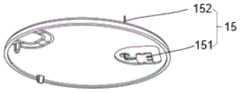
结合参考图1a和图1b。检测器件包括外壳10、电路板13、电池14和传感器15。电路板13、电池14和传感器15设置在外壳10内。具体的,外壳10包括第一外壳体11和第二外壳体12,电路板13和电池14设置在第二外壳体12上,传感器15设置在第一外壳体11内,通过电连接件16与电路板13电连接。Combined reference is made to Figures 1a and 1b. The detection device includes a
在本发明实施例中,传感器15包括体外部分151和体内部分152。体外部分151平铺在第一外壳体11的内侧,可以减少传感器的高度,从而降低分析物检测器件的厚度。同时,体外部分151的一侧固定在第一外壳体12内,防止传感器晃动而造成与电路板13电连接连接不稳定影响电连接可靠性,甚至是造成短路,使分析物检测器件失效。体内部分152相对于体外部分151弯折,并穿过第一外壳体上的通孔111到外侧。在本发明优选实施例中,体内部分152相对于体外部分151呈90°弯折。In an embodiment of the present invention, the
在本发明实施例中,体内部分152刺入到用户皮下,以获取分析物参数信息,体外部分151通过电连接件16与电路板13电连接,以将分析物参数信息通过电路板上的发射器天线(未示出)发送至外界设备。在本发明实施例中,发射器天线与外界设备进行通信。In the embodiment of the present invention, the
在本发明实施例中,第二外壳体内12还设置有固定结构,用于固定电路板13和电池14,电路板13和电池14并排设置在第二外壳体12内,电池14上设置有正负极导电条141和142,电路板13上设置有电源电极(未示出),分别与正负极导电条141和142电连接,实现对分析物检测器件的供电。通过固定结构可使电池14和电路板13稳定连接,实现对分析物检测器件的稳定供电,提高用户体验。In the embodiment of the present invention, the
固定结构包括但不限于定位柱121,支撑台122,电路板13上还设置有拗口131,定位柱121和拗口131卡合,实现电路板13和电池14的径向定位,支撑台122用于支撑电路板13,使电路板13和电池14在高度上达到一致,实现电路板13和电池14的轴向定位。固定结构还可以包括卡合结构,进一步固定电池14的位置。在本发明实施例中,定位柱121,支撑台122,卡合结构以及电路板13上的拗口131的位置和数量在此不做具体限定,可以根据电池14,电路板13和第二外壳体12的形状结构而灵活设计,只要能实现对电路板13和电池14的固定即可。The fixing structure includes but not limited to the
电路板13的形状与电池14和第二外壳体12的形状相适应,下文将详述。The shape of the
在本发明实施例中,电路板13为刚性电路板或柔性电路板,优选的,在本发明实施例中,电路板13为柔性电路板,其他部件的特点灵活设计其形状,优化分析物检测器件的内部设计,还可以进一步减小分析物检测器件的重量,利于分析物检测器件的轻量化发展。In the embodiment of the present invention, the
电路板13、电池14和传感器15的体外部分151封闭的设置在由第一外壳体11、第二外壳体12及传感器的体内部分152形成的封闭空间中,优选的,第一外壳体11和第二外壳体12上设置有相应的卡合结构,通过卡合形成分析物检测器件。具体的卡合结构包括能够互相配合卡合的卡勾、卡块、卡孔、卡槽中的一种或多种,其位置可根据第一外壳体11和第二外壳体12的形状结构而灵活设计,如可设置于对应结构的内部或者表面等位置,在这里并不作具体限制。因此,电池无需先密封的设置在发射器或底壳中,发射器再与底壳进一步卡合,结构简单,布局紧凑,利于分析物检测器件的小型化发展。The
图2a-2c为根据本发明不同实施例的分析物检测器件的传感器和电路板通过不同连接件进行连接的爆炸结构图。2a-2c are exploded structural views of the sensor and the circuit board of the analyte detection device connected by different connectors according to different embodiments of the present invention.
一般的,传感器15上至少设置两个检测电极,即至少包括工作电极和对电极。因此,在本发明一个实施例中,如图2a所示,电连接件16包括至少两个导电区和至少一个绝缘区。相邻两个所述导电区之间设置有所述绝缘区,导电区和绝缘区分别起到电导通和电绝缘的作用。导电区与绝缘区彼此不能够被分离,即导电区与绝缘区分别属于电连接件16整体的一部分。电连接件16只能通过导电区纵向导电,绝缘区使导电区之间彼此绝缘,因此不能横向导电。一个电连接件16同时起到电导通和电绝缘的作用,检测器件内部结构的复杂程度降低,内部结构更紧凑,提高了检测器件的集成度。显然地,当传感器15为三电极体系时,电连接件16包括至少3个导电区和至少两个绝缘区。当传感器15包括更多个电极时,连电接件16中包括更多个互相间隔设置的导电区和绝缘区,电连接的方式将更加灵活。Generally, at least two detection electrodes are arranged on the
在本发明实施例中,电连接件16为弹性连接件,其材料包括弹性塑料、弹性橡胶等。具有弹性的电连接件16能够获得更良好的电接触,同时又起到缓冲作用。当连电连接件16的材料为弹性橡胶时,电连接件16为导电胶条。一个导电胶条即同时起到导电和绝缘的作用,又起到缓冲作用。In the embodiment of the present invention, the
在本发明的另一实施例中,如图2b所示,电连接件26为固体导电胶,具体的,如3M公司的双面导电胶带,双面导电胶带的数量及大小与传感器15体外部分151的引脚(PAD)的大小及数量相适应,在组装过程中,仅需要要分切好的双面导电胶带粘贴在电路板上,再将传感器15的引脚粘贴在双面导电胶带上即可。双面导电胶带的粘性好,能提高传感器15和电路板13的电连接可靠性,同时能固定传感器15,防止传感器15的引脚之间应接触而短路,使分析物检测器件失效。In another embodiment of the present invention, as shown in Figure 2b, the
在本发明的另一实施例中,如图2c所示,电连接件36为弹性导电件,具体的,弹性导电件为压缩弹簧,导电弹片,导电橡胶,导电泡棉,异方性导电胶膜(ACF)等。弹性导电件具有弹性形变和导电性能的结构,可有效的抵抗在使用过程中遇到的振动,冲击等作用力,保证电路板和传感器之间的电连接可靠性。需要说明的是,在本发明实施例中,弹性导电件的数量和位置与传感器15的引脚的数量和位置相适应,且电路板13,传感器15的引脚,与对应的弹性导电件固定连接,防止传感器15的引脚之间应接触而短路,使分析物检测器件失效。In another embodiment of the present invention, as shown in FIG. 2c, the
在本发明的另一实施例中,电连接件16还可以为导电银浆等其他物质,在本发明实施例中,并不限制电连接件16的具体种类,只要能实现传感器15与电路板13的稳定的电连接即可。In another embodiment of the present invention, the
图3a和图3b为根据本发明不同实施例的分析物检测器件的一体式的传感器和电路板的结构示意图。Fig. 3a and Fig. 3b are structural schematic diagrams of an integrated sensor and a circuit board of an analyte detection device according to different embodiments of the present invention.
在本发明实施例中,检测器件包括外壳10、电路板13、电池14和传感器15。电路板13、电池14和传感器15设置在外壳10内,外壳10包括第一外壳体11和第二外壳体12,电路板13和电池14设置在第二外壳体12上,传感器15与电路板13为一体式结构。传感器15与电路板13为一体式结构可以避免因连接件或连接方式的缺陷而造成传感器15与电路板13电连接性能不可靠,进而提高传感器15与电路板13的电连接可靠性,同时减少分析物检测器件中的部件数量,降低分析物检测器件的内部设计的复杂度,优化分析物检测器件的内部设计。另一方面,电路板,电池和传感器的体外部分都设置第一外壳体、第二外壳体和传感器的体内部分形成的封闭空间中,电池不再需要先封闭的设置在发射器或底壳中,发射器再与底壳进一步卡合形成分析物检测器件,结构简单,布局紧凑,利于分析物检测器件的小型化发展。In the embodiment of the present invention, the detection device includes a
在本发明一个实施例中,如图3a所示,传感器15和电路板13为柔性电路板,在本发明实施例中,柔性电路板为柔性线路板(FPC)。传感器包括电极基材和在基材表面形成的电极和导线,具体的,传感器15的电极基材与FPC为一体式结构。在制备过程性,将FPC分割成传感器15和电路板13所需要的形状,以传感器15对应部分的FPC为电极基材,在基材上直接喷涂出对应的对电极图形、参比电极图形及连接导线,喷涂的材料可使用纳米铂金或纳米银;也可使用喷墨微打印的方法,在电极基材上直接打印出相应的对电极图形、参比电极图形及连接导线,打印的材料可使用纳米铂金或纳米银;还可以采用光刻技术在基材上制备好相应的图形及掩膜,然后通过溅射技术溅射贵金属金,形成连接导线,然后分别在对电极位置溅射上铂形成对电极,在参比电极位置溅射银/氯化银形成参比电极。工作电极的制备可以使用光刻、电铸和注塑技术制作MEMS(微机电系统,Micro-Electro-Mechanic System)模具,利用热模压成型技术进行微塑铸微光纤阵列,然后在工作电极上喷涂铟锡氧化物。In one embodiment of the present invention, as shown in FIG. 3a, the
在本发明的其他实施例中,柔性电路板还可以是以PI(聚酰亚胺)膜或PET(聚酯)膜为基材的电路板,或以聚合物膜,例如PEN(聚邻苯二甲酸乙二酯),PTFE(聚四氟乙烯)和芳纶等为基材的电路板,或液晶聚合物(LCP)为基材的电路板。在基材上制备电极及导线形成传感器的制备方法如前所述,在此不再重复。In other embodiments of the present invention, the flexible circuit board can also be a circuit board based on PI (polyimide) film or PET (polyester) film, or a polymer film such as PEN (polyphthalate) Ethylene diformate), PTFE (polytetrafluoroethylene) and aramid, etc. as the substrate, or liquid crystal polymer (LCP) as the substrate. The method for preparing electrodes and wires on the substrate to form sensors is as described above and will not be repeated here.
在本发明另一实施例中,如图3b所示,传感器15和电路板13为软硬结合板,具体的,电路板为硬性线路板(PCB),传感器基材为柔性电路板的基材,具体的基材种类包括但不限于如前所述的FPC,PI膜、PET膜,聚合物膜,液晶聚合物膜等。经过压合等工艺,柔性电路板的基材嵌入PCB中形成一体结构,再在基材上制备电极及导线形成传感器,具体电极及导线的制备方法如前所述,在此不再重复。In another embodiment of the present invention, as shown in Figure 3b, the
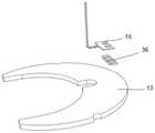
在本发明实施例中,传感器15包括体外部分151和体内部分152。体内部分152相对于体外部分151弯折,并穿过第一外壳体上的通孔111到外侧。可以减少传感器的高度,从而降低分析物检测器件的厚度。在本发明优选实施例中,体内部分152相对于体外部分151呈90°弯折。In an embodiment of the present invention, the
在本发明实施例中,体内部分152刺入到用户皮下,以获取分析物参数信息,体外部分151与电路板13为一体结构,将分析物参数信息通过电路板13上的发射器天线发送至外界设备。在本发明实施例中,发射器天线与外界设备进行通信。In the embodiment of the present invention, the
图4a-图4c为电路板,电池和壳体的形状示意图。4a-4c are schematic diagrams of the shapes of the circuit board, the battery and the housing.
在本发明实施例中,电路板13和电池14并排设置在第二外壳体12中,第二外壳体12中设置还有固定结构,用于固定电路板和电池,具体的固定方式如前所述。相对于电池14与电路板13呈堆叠设置的方案,电路板13和电池14并排设置可进一步减小分析物检测器件的厚度,同时电路板13的形状与电池14和第二外壳体12的形状相适应。这里“相适应”是指,在电池14已占据一定第二外壳体12的前提下,通过对电路板13的形状进行设计,以填充第二外壳体12的内部剩余可用空间。如,第二外壳体12为圆形,电池为纽扣电池等圆形电池,且为第二外壳体12偏心的圆形时,电路板13可被设计为月牙形;电池14为圆形,且为第二外壳体12同心的圆形时,电路板13可被设计为圆环形;电池14为为方形电池,且为第二外壳体12偏心的方形时,电路板13可被设计为“7”字形。除上述电路板13的可能形状外,电路板13还可被设计为其他形状,只要能与电池14共同填充第二外壳体12的内部空间即可。电路板13与电池14并排设置,且与第二外壳体12的适应性设置提高了外壳的内部空间利用率,从而减小了外壳的尺寸,有利于分析物检测器件的小型化设计。In the embodiment of the present invention, the
需要说明的是,根据电路板13和电池14在第二外壳体12内的形状的不同,第二外壳体12内固定结构也相应的进行调整,具体的调整方式在此不做具体限定,只要能实现对电池14和电路板13的固定即可。It should be noted that, according to the different shapes of the
在本发明实施例中,在第一外壳体11的外侧还设置有粘性贴片(图中未示出),粘性贴片用于将分析物检测器件固定在用户皮肤表面。粘性贴片的表面还设置有保护膜,保护膜的洛氏硬度大于粘性贴片,在本发明优选实施例中,保护膜的洛氏硬度为80HRM~100HRM。保护膜的外沿轮廓与粘性贴片的外沿轮廓相适应,这里相适应是指保护膜的外沿轮廓尺寸、弯折半径、形状等参数均与粘性贴片的外沿轮廓参数一致,使得粘性贴片外沿的每一处均能与保护膜贴合,可以防止粘性贴片外沿发生翘边,进而防止分析物检测器件发生位移或者脱落,延长分析物检测装置的使用寿命,增强了用户体验。In the embodiment of the present invention, an adhesive patch (not shown in the figure) is provided on the outside of the first
综上所述,本发明提供了一种紧凑型分析物检测器件,包括外壳,外壳内设置有电路板,电池和传感器,外壳包括第一外壳体和第二外壳体,电路板,电池和传感器的体外部分都设置第一外壳体、第二外壳体和传感器的体内部分形成的封闭空间中,结构简单,布局紧凑,利于分析物检测器件的小型化发展。In summary, the present invention provides a compact analyte detection device, including a housing, a circuit board, a battery and a sensor are arranged inside the housing, and the housing includes a first outer shell and a second outer shell, a circuit board, a battery and a sensor The external part of the sensor is arranged in the closed space formed by the first outer casing, the second outer casing and the inner part of the sensor, the structure is simple, the layout is compact, and it is beneficial to the miniaturization development of the analyte detection device.
虽然已经通过示例对本发明的一些特定实施例进行了详细说明,但是本领域的技术人员应该理解,以上示例仅是为了进行说明,而不是为了限制本发明的范围。本领域的技术人员应该理解,可在不脱离本发明的范围和精神的情况下,对以上实施例进行修改。本发明的范围由所附权利要求来限定。Although some specific embodiments of the present invention have been described in detail through examples, those skilled in the art should understand that the above examples are for illustration only, rather than limiting the scope of the present invention. Those skilled in the art will appreciate that modifications can be made to the above embodiments without departing from the scope and spirit of the invention. The scope of the invention is defined by the appended claims.
Claims (15)
Translated fromChineseApplications Claiming Priority (2)
| Application Number | Priority Date | Filing Date | Title |
|---|---|---|---|
| PCT/CN2021/120856WO2023044889A1 (en) | 2021-09-27 | 2021-09-27 | Analyte detection system |
| CNPCT/CN2021/120856 | 2021-09-27 |
Publications (1)
| Publication Number | Publication Date |
|---|---|
| CN115868975Atrue CN115868975A (en) | 2023-03-31 |
Family
ID=85659983
Family Applications (19)
| Application Number | Title | Priority Date | Filing Date |
|---|---|---|---|
| CN202111492205.2APendingCN115882086A (en) | 2021-09-27 | 2021-12-08 | Battery housing integrated analyte detection device |
| CN202111492182.5APendingCN115881994A (en) | 2021-09-27 | 2021-12-08 | Battery housing integrated analyte detection device |
| CN202111651879.2APendingCN115884555A (en) | 2021-09-27 | 2021-12-30 | Circuit-embedded analyte detection devices |
| CN202210110638.5APendingCN115868975A (en) | 2021-09-27 | 2022-01-29 | Compact Analyte Detection Devices |
| CN202210110640.2APendingCN115877010A (en) | 2021-09-27 | 2022-01-29 | Integrated analyte detection device |
| CN202210113839.0AActiveCN115844395B (en) | 2021-09-27 | 2022-01-30 | Sensor calibration method |
| CN202210113852.6AActiveCN115868986B (en) | 2021-09-27 | 2022-01-30 | Calibration method based on sensor physical characteristics |
| CN202210113842.2APendingCN115868984A (en) | 2021-09-27 | 2022-01-30 | Analyte detection device and detection method |
| CN202210113841.8APendingCN115868983A (en) | 2021-09-27 | 2022-01-30 | Calibration-free analyte detection device |
| CN202210113854.5APendingCN115868981A (en) | 2021-09-27 | 2022-01-30 | Sensor Calibration Method |
| CN202210113845.6APendingCN115868985A (en) | 2021-09-27 | 2022-01-30 | Analyte detection device and detection method |
| CN202210113857.9APendingCN115868987A (en) | 2021-09-27 | 2022-01-30 | Calibration-free analyte detection device |
| CN202210516562.6APendingCN115868978A (en) | 2021-09-27 | 2022-05-12 | Analyte detection system and method for controlling analyte detection device |
| CN202210692759.5APendingCN115868979A (en) | 2021-09-27 | 2022-06-17 | Systems and methods for implementing a communication link for an analyte detection device |
| CN202222005702.1UActiveCN218922582U (en) | 2021-09-27 | 2022-08-01 | Analyte detection device communication system |
| CN202210916885.4APendingCN115884332A (en) | 2021-09-27 | 2022-08-01 | Analyte detection device communication system |
| CN202380026837.0APendingCN119968155A (en) | 2021-09-27 | 2023-04-13 | Energy-saving analyte detection system |
| CN202310406345.6APendingCN117080718A (en) | 2021-09-27 | 2023-04-17 | Antenna for analyte detection device |
| CN202320850543.7UActiveCN219937367U (en) | 2021-09-27 | 2023-04-17 | Analyte detection device |
Family Applications Before (3)
| Application Number | Title | Priority Date | Filing Date |
|---|---|---|---|
| CN202111492205.2APendingCN115882086A (en) | 2021-09-27 | 2021-12-08 | Battery housing integrated analyte detection device |
| CN202111492182.5APendingCN115881994A (en) | 2021-09-27 | 2021-12-08 | Battery housing integrated analyte detection device |
| CN202111651879.2APendingCN115884555A (en) | 2021-09-27 | 2021-12-30 | Circuit-embedded analyte detection devices |
Family Applications After (15)
| Application Number | Title | Priority Date | Filing Date |
|---|---|---|---|
| CN202210110640.2APendingCN115877010A (en) | 2021-09-27 | 2022-01-29 | Integrated analyte detection device |
| CN202210113839.0AActiveCN115844395B (en) | 2021-09-27 | 2022-01-30 | Sensor calibration method |
| CN202210113852.6AActiveCN115868986B (en) | 2021-09-27 | 2022-01-30 | Calibration method based on sensor physical characteristics |
| CN202210113842.2APendingCN115868984A (en) | 2021-09-27 | 2022-01-30 | Analyte detection device and detection method |
| CN202210113841.8APendingCN115868983A (en) | 2021-09-27 | 2022-01-30 | Calibration-free analyte detection device |
| CN202210113854.5APendingCN115868981A (en) | 2021-09-27 | 2022-01-30 | Sensor Calibration Method |
| CN202210113845.6APendingCN115868985A (en) | 2021-09-27 | 2022-01-30 | Analyte detection device and detection method |
| CN202210113857.9APendingCN115868987A (en) | 2021-09-27 | 2022-01-30 | Calibration-free analyte detection device |
| CN202210516562.6APendingCN115868978A (en) | 2021-09-27 | 2022-05-12 | Analyte detection system and method for controlling analyte detection device |
| CN202210692759.5APendingCN115868979A (en) | 2021-09-27 | 2022-06-17 | Systems and methods for implementing a communication link for an analyte detection device |
| CN202222005702.1UActiveCN218922582U (en) | 2021-09-27 | 2022-08-01 | Analyte detection device communication system |
| CN202210916885.4APendingCN115884332A (en) | 2021-09-27 | 2022-08-01 | Analyte detection device communication system |
| CN202380026837.0APendingCN119968155A (en) | 2021-09-27 | 2023-04-13 | Energy-saving analyte detection system |
| CN202310406345.6APendingCN117080718A (en) | 2021-09-27 | 2023-04-17 | Antenna for analyte detection device |
| CN202320850543.7UActiveCN219937367U (en) | 2021-09-27 | 2023-04-17 | Analyte detection device |
Country Status (4)
| Country | Link |
|---|---|
| US (13) | US20240389890A1 (en) |
| EP (6) | EP4408278A4 (en) |
| CN (19) | CN115882086A (en) |
| WO (16) | WO2023044889A1 (en) |
Cited By (3)
| Publication number | Priority date | Publication date | Assignee | Title |
|---|---|---|---|---|
| CN115877010A (en)* | 2021-09-27 | 2023-03-31 | 上海移宇科技股份有限公司 | Integrated analyte detection device |
| WO2025039161A1 (en)* | 2023-08-21 | 2025-02-27 | 上海联影微电子科技有限公司 | Analyte sensor |
| WO2025152020A1 (en)* | 2024-01-16 | 2025-07-24 | 上海移宇科技有限公司 | Analyte detection system |
Families Citing this family (4)
| Publication number | Priority date | Publication date | Assignee | Title |
|---|---|---|---|---|
| EP4346587A4 (en)* | 2021-05-31 | 2024-10-30 | Medtrum Technologies Inc. | ANALYTE DETECTION DEVICE INTEGRATED INTO A BATTERY ENCLOSURE |
| US20240237926A1 (en)* | 2021-05-31 | 2024-07-18 | Medtrum Technologies Inc. | Highly integrated analyte detection device |
| USD1067078S1 (en)* | 2021-06-29 | 2025-03-18 | Medtrum Technologies Inc. | Analyte detection device |
| CN116707095A (en)* | 2023-07-16 | 2023-09-05 | 王汉武 | Portable strong light flashlight power bank with waterproof function |
Citations (6)
| Publication number | Priority date | Publication date | Assignee | Title |
|---|---|---|---|---|
| US20160157759A1 (en)* | 2014-03-07 | 2016-06-09 | Medtrum Technologies Inc. | Analyte sensing system |
| CN105686807A (en)* | 2009-08-31 | 2016-06-22 | 雅培糖尿病护理公司 | Medical devices |
| CN106324235A (en)* | 2016-08-12 | 2017-01-11 | 上海移宇科技股份有限公司 | One-step type full-integration body fluid sampling analysis pen |
| CN112120709A (en)* | 2020-09-27 | 2020-12-25 | 微泰医疗器械(杭州)有限公司 | Blood sugar monitoring device |
| CN113274004A (en)* | 2020-02-20 | 2021-08-20 | 上海移宇科技股份有限公司 | High reliability analyte detection device |
| CN115877010A (en)* | 2021-09-27 | 2023-03-31 | 上海移宇科技股份有限公司 | Integrated analyte detection device |
Family Cites Families (101)
| Publication number | Priority date | Publication date | Assignee | Title |
|---|---|---|---|---|
| US8465425B2 (en)* | 1998-04-30 | 2013-06-18 | Abbott Diabetes Care Inc. | Analyte monitoring device and methods of use |
| US8688188B2 (en)* | 1998-04-30 | 2014-04-01 | Abbott Diabetes Care Inc. | Analyte monitoring device and methods of use |
| US7011630B2 (en)* | 2001-06-22 | 2006-03-14 | Animas Technologies, Llc | Methods for computing rolling analyte measurement values, microprocessors comprising programming to control performance of the methods, and analyte monitoring devices employing the methods |
| US6917885B2 (en)* | 2003-06-06 | 2005-07-12 | Steris Inc. | Method and apparatus for formulating and controlling chemical concentration in a gas mixture |
| US8060173B2 (en)* | 2003-08-01 | 2011-11-15 | Dexcom, Inc. | System and methods for processing analyte sensor data |
| US7723127B2 (en)* | 2005-03-03 | 2010-05-25 | Novx Systems Inc. | Immunoassay with extended dynamic range |
| EP1960018A1 (en)* | 2005-12-08 | 2008-08-27 | Novo Nordisk A/S | Medical system comprising a sensor device |
| US8346335B2 (en)* | 2008-03-28 | 2013-01-01 | Abbott Diabetes Care Inc. | Analyte sensor calibration management |
| US8140312B2 (en)* | 2007-05-14 | 2012-03-20 | Abbott Diabetes Care Inc. | Method and system for determining analyte levels |
| CA2685167A1 (en)* | 2007-05-14 | 2008-11-27 | Abbott Diabetes Care Inc. | Method and apparatus for providing data processing and control in a medical communication system |
| US7783442B2 (en)* | 2007-10-31 | 2010-08-24 | Medtronic Minimed, Inc. | System and methods for calibrating physiological characteristic sensors |
| US9289168B2 (en)* | 2008-12-29 | 2016-03-22 | Medtronic Minimed, Inc. | System and/or method for glucose sensor calibration |
| US8103456B2 (en)* | 2009-01-29 | 2012-01-24 | Abbott Diabetes Care Inc. | Method and device for early signal attenuation detection using blood glucose measurements |
| US9402544B2 (en)* | 2009-02-03 | 2016-08-02 | Abbott Diabetes Care Inc. | Analyte sensor and apparatus for insertion of the sensor |
| US8110081B2 (en)* | 2009-05-22 | 2012-02-07 | Medical Graphics Corporation | Oxygen sensor improvement method |
| US10050254B2 (en)* | 2009-09-04 | 2018-08-14 | Johnson Controls Technology Company | Secondary battery with improved destratification |
| US9089292B2 (en)* | 2010-03-26 | 2015-07-28 | Medtronic Minimed, Inc. | Calibration of glucose monitoring sensor and/or insulin delivery system |
| US20110269164A1 (en)* | 2010-04-30 | 2011-11-03 | Arkray, Inc. | Measuring Device, Measuring Method, and Program |
| US8957777B2 (en)* | 2010-06-30 | 2015-02-17 | Welch Allyn, Inc. | Body area network pairing improvements for clinical workflows |
| DK2621339T3 (en)* | 2010-09-29 | 2020-02-24 | Dexcom Inc | ADVANCED SYSTEM FOR CONTINUOUS ANALYTICAL MONITORING |
| EP3505065B1 (en)* | 2011-09-23 | 2021-03-03 | Dexcom, Inc. | Systems and methods for processing and transmitting sensor data |
| US9462970B2 (en)* | 2012-04-24 | 2016-10-11 | Abbott Diabetes Care Inc. | Methods of lag-compensation for analyte measurements, and devices related thereto |
| US8990277B2 (en)* | 2012-05-08 | 2015-03-24 | GM Global Technology Operations LLC | Method for searching a lookup table |
| CN102735284A (en)* | 2012-06-25 | 2012-10-17 | 青岛海信移动通信技术股份有限公司 | Method and device for calibrating sensor |
| ES2759560T3 (en)* | 2012-06-28 | 2020-05-11 | Hoffmann La Roche | Device for monitoring at least one bodily function of a user and its manufacturing procedure |
| DE102012215883A1 (en)* | 2012-09-07 | 2014-03-13 | Robert Bosch Gmbh | Energy storage e.g. lithium ion battery mounted in e.g. electric vehicle, has detection unit that is provided for detecting component located within housing or reaction product of component, during operation of energy storage |
| US9211092B2 (en)* | 2013-01-03 | 2015-12-15 | Dexcom, Inc. | End of life detection for analyte sensors |
| ES2969238T3 (en)* | 2013-03-14 | 2024-05-17 | Dexcom Inc | Systems and methods for processing and transmitting sensor data |
| US10335075B2 (en)* | 2013-03-14 | 2019-07-02 | Dexcom, Inc. | Advanced calibration for analyte sensors |
| US9931036B2 (en)* | 2013-03-14 | 2018-04-03 | Dexcom, Inc. | Systems and methods for processing and transmitting sensor data |
| EP3744247A1 (en)* | 2013-03-15 | 2020-12-02 | Abbott Diabetes Care, Inc. | Medical device data processing and communication methods and systems |
| AU2014260023B2 (en)* | 2013-04-30 | 2018-12-06 | Abbott Diabetes Care Inc. | Systems, devices, and methods for energy efficient electrical device activation |
| EP3082574B1 (en)* | 2013-12-16 | 2023-07-12 | Dexcom, Inc. | Systems and methods for monitoring and managing life of a battery in an analyte sensor system worn by a user |
| US20170069940A1 (en)* | 2014-03-06 | 2017-03-09 | Unicell Llc | Battery cells and arrangements |
| EP2950058B1 (en)* | 2014-05-28 | 2018-03-28 | Axis AB | Calibration data in a sensor system |
| RU2622880C2 (en)* | 2014-08-22 | 2017-06-20 | Нокиа Текнолоджиз Ой | Sensor information processing |
| CN204216628U (en)* | 2014-11-24 | 2015-03-18 | 东莞劲胜精密组件股份有限公司 | A device integrating a battery and a housing |
| US9332940B1 (en)* | 2015-01-05 | 2016-05-10 | Analog Devices, Inc. | Compact wearable biological sensor modules |
| US9901293B2 (en)* | 2015-02-24 | 2018-02-27 | Senseonics, Incorporated | Analyte sensor |
| EP3101571B1 (en)* | 2015-06-03 | 2018-05-02 | Roche Diabetes Care GmbH | Measurement system for measuring the concentration of an analyte with a subcutaneous analyte sensor |
| US10765353B2 (en)* | 2015-07-02 | 2020-09-08 | Verily Life Sciences Llc | Calibration methods for a bandage-type analyte sensor |
| US10470660B2 (en)* | 2015-09-10 | 2019-11-12 | Dexcom, Inc. | Transcutaneous analyte sensors and monitors, calibration thereof, and associated methods |
| CN105180995B (en)* | 2015-09-11 | 2019-02-19 | 武汉泰利美信医疗科技有限公司 | A kind of measurement calibration system and method |
| EP3170451A1 (en)* | 2015-11-19 | 2017-05-24 | Roche Diabetes Care GmbH | Sensor and sensor assembly for detecting an analyte in a body fluid |
| US12144613B2 (en)* | 2015-12-21 | 2024-11-19 | Dexcom, Inc. | Continuous analyte monitoring system power conservation |
| KR101984671B1 (en)* | 2015-12-23 | 2019-07-05 | 한국가스안전공사 | Method of automatically calibrating sensor output characteristic of gas detector |
| US20170181672A1 (en)* | 2015-12-28 | 2017-06-29 | Medtronic Minimed, Inc. | Sensor systems, devices, and methods for continuous glucose monitoring |
| EP4029434B1 (en)* | 2015-12-28 | 2025-04-30 | Dexcom, Inc. | Intelligent wireless communications for continuous analyte monitoring |
| WO2017117416A1 (en)* | 2015-12-30 | 2017-07-06 | Dexcom, Inc. | System and method for factory calibration or reduced calibration of an indwelling sensor based on sensitivity profile |
| CA3007516C (en)* | 2016-03-31 | 2021-11-23 | Dexcom, Inc. | Systems and methods for display device and sensor electronics unit communication |
| US20170290535A1 (en)* | 2016-04-08 | 2017-10-12 | Medtronic Minimed, Inc. | Analyte sensor with indicators |
| US10172559B2 (en)* | 2016-05-13 | 2019-01-08 | Pacesetter, Inc. | Implantable device header with embedded sensor and antenna |
| EP3243434B1 (en)* | 2016-05-13 | 2022-07-20 | Roche Diabetes Care GmbH | Analyte measurement system initialization method |
| CN105962919A (en)* | 2016-06-18 | 2016-09-28 | 欧志洪 | Intelligent wristband watch with pulse detector |
| DK3261357T3 (en)* | 2016-06-23 | 2019-03-11 | Hoffmann La Roche | PROCEDURE FOR A WIRELESS DATA COMMUNICATION BETWEEN A SENSOR SYSTEM AND A RECEIVER, A SYSTEM FOR A WIRELESS DATA COMMUNICATION AND COMPUTER PROGRAM PRODUCT |
| EP3487405B1 (en)* | 2016-07-20 | 2023-07-12 | Dexcom, Inc. | System and method for wireless communication of glucose data |
| CN106137214A (en)* | 2016-08-12 | 2016-11-23 | 上海移宇科技股份有限公司 | A kind of transcutaneous analyte sensing equipment and installation method thereof |
| WO2018031803A1 (en)* | 2016-08-12 | 2018-02-15 | Dexcom, Inc. | Systems and methods for health data visualization and user support tools for continuous glucose monitoring |
| US10788445B2 (en)* | 2017-03-17 | 2020-09-29 | The University Of Akron | Polymer electrolyte membrane fuel cell (PEMFC) sensor |
| CN110461232A (en)* | 2017-04-04 | 2019-11-15 | 豪夫迈·罗氏有限公司 | Body Wearable Medical Devices |
| EP3609404A4 (en)* | 2017-04-12 | 2020-12-23 | Roche Diabetes Care GmbH | MEDICAL SYSTEM |
| CN107219329B (en)* | 2017-04-13 | 2019-04-26 | 北京理工大学 | Low power consumption gas detection method and device |
| EP3618712A1 (en)* | 2017-05-03 | 2020-03-11 | Abbott Diabetes Care Inc. | Systems, devices, and methods with duration-based adjustment of sensor data |
| CN110650675B (en)* | 2017-05-22 | 2022-12-06 | 贝克顿·迪金森公司 | System, apparatus and method for secure wireless pairing between two devices using embedded out-of-band key generation |
| ES2905929T3 (en)* | 2017-05-23 | 2022-04-12 | Hoffmann La Roche | Sensor system and procedure for its manufacture |
| EP4218568A1 (en)* | 2017-08-18 | 2023-08-02 | Abbott Diabetes Care Inc. | Analyte monitoring system storing a measured electrical characteristic of the in vivo analyte sensor of the system as individualized calibration information |
| US20190120785A1 (en)* | 2017-10-24 | 2019-04-25 | Dexcom, Inc. | Pre-connected analyte sensors |
| CN111601540B (en)* | 2017-10-27 | 2023-08-08 | 豪夫迈·罗氏有限公司 | Apparatus and method for detecting at least one analyte in a user's bodily fluid |
| US11213230B2 (en)* | 2017-12-13 | 2022-01-04 | Medtronic Minimed, Inc. | Optional sensor calibration in continuous glucose monitoring |
| CN109976997B (en)* | 2017-12-28 | 2022-12-27 | 北京京东尚科信息技术有限公司 | Test method and device |
| CN108415024B (en)* | 2018-01-24 | 2020-06-23 | Oppo广东移动通信有限公司 | Proximity sensor calibration method and device, mobile terminal and computer readable medium |
| EP3787479A4 (en)* | 2018-05-03 | 2022-02-16 | DexCom, Inc. | AUTOMATIC ANALYZE SENSOR CALIBRATION AND ERROR DETECTION |
| US11350857B2 (en)* | 2018-05-03 | 2022-06-07 | Dexcom, Inc. | Systems and methods for activating analyte sensor electronics |
| US11850045B2 (en)* | 2018-05-04 | 2023-12-26 | Dexcom, Inc. | Systems and methods relating to an analyte sensor system having a battery located within a disposable base |
| CN108682755A (en)* | 2018-05-09 | 2018-10-19 | 广东弘捷新能源有限公司 | Button cell and its manufacturing method |
| CN108968920A (en)* | 2018-07-12 | 2018-12-11 | 维沃移动通信有限公司 | A kind of data detection method and electronic equipment |
| US11666240B2 (en)* | 2019-01-03 | 2023-06-06 | Northwestern University | Ultra-low power, miniaturized electronic systems for monitoring physical parameters with wireless communication capabilities and applications of same |
| US20200330007A1 (en)* | 2019-04-22 | 2020-10-22 | Medtronic Minimed, Inc. | Sensor with substrate including integrated electrical and chemical components and methods for fabricating the same |
| US11317867B2 (en)* | 2019-04-23 | 2022-05-03 | Medtronic Minimed, Inc. | Flexible physiological characteristic sensor assembly |
| CN110162759A (en)* | 2019-05-22 | 2019-08-23 | 苏州高新区苏新立创环境科研技术有限公司 | Assessment report generation method, storage medium and system |
| MX2021008013A (en)* | 2019-06-04 | 2021-08-05 | Waveform Tech Inc | Sensor signal processing with kalman-based calibration. |
| CN113340969A (en)* | 2019-06-24 | 2021-09-03 | 深圳硅基传感科技有限公司 | Factory calibration method of glucose sensor without finger blood calibration |
| US12193809B2 (en)* | 2019-08-02 | 2025-01-14 | Bionime Corporation | Physiological signal monitoring device |
| EP4017357A4 (en)* | 2019-08-19 | 2023-04-19 | Medtrum Technologies Inc. | MEASURING DEVICE |
| CN110764999A (en)* | 2019-09-06 | 2020-02-07 | 深圳壹账通智能科技有限公司 | Automatic testing method and device, computer device and storage medium |
| US11963763B2 (en)* | 2019-09-10 | 2024-04-23 | Ascensia Diabetes Care Holdings Ag | Methods and apparatus information gathering, error detection and analyte concentration determination during continuous analyte sensing |
| US11654235B2 (en)* | 2019-09-12 | 2023-05-23 | Medtronic Minimed, Inc. | Sensor calibration using fabrication measurements |
| US11152664B2 (en)* | 2019-12-24 | 2021-10-19 | Anexa Labs Llc | Compact electronics with optical sensors |
| WO2021164181A1 (en)* | 2020-02-20 | 2021-08-26 | Medtrum Technologies Inc. | A mounting unit of an analyte detection device and a mounting method thereof |
| CN116706077A (en)* | 2020-03-09 | 2023-09-05 | 宁德新能源科技有限公司 | Battery cell and battery with same |
| AU2021236235A1 (en)* | 2020-03-11 | 2022-08-18 | Abbott Diabetes Care Inc. | Graphical user interfaces for analyte monitoring systems |
| CN111781171A (en)* | 2020-06-12 | 2020-10-16 | 迈克医疗电子有限公司 | Method, device and equipment for measuring object parameters in-vitro detection sample |
| CN112217982A (en)* | 2020-12-08 | 2021-01-12 | 武汉仟目激光有限公司 | Compact TOF camera module for 3D sensing |
| CN112568902A (en)* | 2020-12-15 | 2021-03-30 | 无锡轲虎医疗科技有限责任公司 | Noninvasive blood glucose calibration method based on blood glucose value |
| CN213583956U (en)* | 2020-12-16 | 2021-06-29 | 江西炳昶电池科技有限公司 | Polymer battery structure with double folded edges |
| CN213660476U (en)* | 2020-12-23 | 2021-07-09 | 惠州市哈工新能源科技有限公司 | Quick-charging polymer lithium battery |
| CN112766067A (en)* | 2020-12-31 | 2021-05-07 | 杭州艾芯智能科技有限公司 | Method and system for acquiring 3D face recognition module calibration data, computer and storage medium |
| CN112806975A (en)* | 2021-02-01 | 2021-05-18 | 深圳益卡思科技发展有限公司 | Sleep monitoring device, method and medium based on millimeter wave radar |
| CN113219033B (en)* | 2021-04-30 | 2022-08-30 | 福州大学 | Correction-free quantitative measurement method of electrochemical aptamer sensor |
| CN113222663B (en)* | 2021-05-11 | 2024-07-19 | 北京京东振世信息技术有限公司 | Data generation method, device, terminal equipment and storage medium |
| CN216257100U (en)* | 2021-09-27 | 2022-04-12 | 上海移宇科技股份有限公司 | Analyte Detection Device Mounting Unit |
- 2021
- 2021-09-27WOPCT/CN2021/120856patent/WO2023044889A1/ennot_activeCeased
- 2021-09-27EPEP21958007.3Apatent/EP4408278A4/enactivePending
- 2021-09-27USUS18/693,953patent/US20240389890A1/enactivePending
- 2021-12-08CNCN202111492205.2Apatent/CN115882086A/enactivePending
- 2021-12-08USUS18/694,421patent/US20240389896A1/enactivePending
- 2021-12-08WOPCT/CN2021/136529patent/WO2023045100A1/ennot_activeCeased
- 2021-12-08EPEP21958211.1Apatent/EP4408282A4/enactivePending
- 2021-12-08USUS18/693,525patent/US20240389893A1/enactivePending
- 2021-12-08EPEP21958210.3Apatent/EP4408256A4/enactivePending
- 2021-12-08WOPCT/CN2021/136522patent/WO2023045099A1/ennot_activeCeased
- 2021-12-08CNCN202111492182.5Apatent/CN115881994A/enactivePending
- 2021-12-30EPEP21958277.2Apatent/EP4408283A4/enactivePending
- 2021-12-30USUS18/693,159patent/US20240390893A1/enactivePending
- 2021-12-30CNCN202111651879.2Apatent/CN115884555A/enactivePending
- 2021-12-30WOPCT/CN2021/143080patent/WO2023045167A1/ennot_activeCeased
- 2022
- 2022-01-28WOPCT/CN2022/074624patent/WO2023045206A1/ennot_activeCeased
- 2022-01-28WOPCT/CN2022/074617patent/WO2023045205A1/ennot_activeCeased
- 2022-01-29CNCN202210110638.5Apatent/CN115868975A/enactivePending
- 2022-01-29CNCN202210110640.2Apatent/CN115877010A/enactivePending
- 2022-01-30CNCN202210113839.0Apatent/CN115844395B/enactiveActive
- 2022-01-30WOPCT/CN2022/075207patent/WO2023045213A1/ennot_activeCeased
- 2022-01-30USUS18/694,994patent/US20240398286A1/enactivePending
- 2022-01-30USUS18/694,997patent/US20240389911A1/enactivePending
- 2022-01-30WOPCT/CN2022/075208patent/WO2023045214A1/ennot_activeCeased
- 2022-01-30USUS18/694,420patent/US20240389895A1/enactivePending
- 2022-01-30CNCN202210113852.6Apatent/CN115868986B/enactiveActive
- 2022-01-30CNCN202210113842.2Apatent/CN115868984A/enactivePending
- 2022-01-30WOPCT/CN2022/075204patent/WO2023045211A1/ennot_activeCeased
- 2022-01-30CNCN202210113841.8Apatent/CN115868983A/enactivePending
- 2022-01-30WOPCT/CN2022/075205patent/WO2023045212A1/ennot_activeCeased
- 2022-01-30USUS18/693,958patent/US20240389910A1/enactivePending
- 2022-01-30CNCN202210113854.5Apatent/CN115868981A/enactivePending
- 2022-01-30CNCN202210113845.6Apatent/CN115868985A/enactivePending
- 2022-01-30CNCN202210113857.9Apatent/CN115868987A/enactivePending
- 2022-01-30WOPCT/CN2022/075203patent/WO2023045210A1/ennot_activeCeased
- 2022-01-30USUS18/693,954patent/US20240389909A1/enactivePending
- 2022-01-30USUS18/695,366patent/US20250221644A1/enactivePending
- 2022-01-30WOPCT/CN2022/075201patent/WO2023045209A1/ennot_activeCeased
- 2022-01-30WOPCT/CN2022/075200patent/WO2023045208A1/ennot_activeCeased
- 2022-05-12CNCN202210516562.6Apatent/CN115868978A/enactivePending
- 2022-06-17USUS18/693,956patent/US20240389894A1/enactivePending
- 2022-06-17EPEP22871493.7Apatent/EP4410048A4/enactivePending
- 2022-06-17WOPCT/CN2022/099387patent/WO2023045432A1/ennot_activeCeased
- 2022-06-17CNCN202210692759.5Apatent/CN115868979A/enactivePending
- 2022-08-01CNCN202222005702.1Upatent/CN218922582U/enactiveActive
- 2022-08-01CNCN202210916885.4Apatent/CN115884332A/enactivePending
- 2022-08-01EPEP22871624.7Apatent/EP4409942A4/enactivePending
- 2022-08-01USUS18/695,364patent/US20250221640A1/enactivePending
- 2022-08-01WOPCT/CN2022/109439patent/WO2023045566A1/ennot_activeCeased
- 2023
- 2023-04-13WOPCT/CN2023/088036patent/WO2023216800A1/ennot_activeCeased
- 2023-04-13USUS18/849,534patent/US20250221638A1/enactivePending
- 2023-04-13CNCN202380026837.0Apatent/CN119968155A/enactivePending
- 2023-04-17CNCN202310406345.6Apatent/CN117080718A/enactivePending
- 2023-04-17CNCN202320850543.7Upatent/CN219937367U/enactiveActive
Patent Citations (6)
| Publication number | Priority date | Publication date | Assignee | Title |
|---|---|---|---|---|
| CN105686807A (en)* | 2009-08-31 | 2016-06-22 | 雅培糖尿病护理公司 | Medical devices |
| US20160157759A1 (en)* | 2014-03-07 | 2016-06-09 | Medtrum Technologies Inc. | Analyte sensing system |
| CN106324235A (en)* | 2016-08-12 | 2017-01-11 | 上海移宇科技股份有限公司 | One-step type full-integration body fluid sampling analysis pen |
| CN113274004A (en)* | 2020-02-20 | 2021-08-20 | 上海移宇科技股份有限公司 | High reliability analyte detection device |
| CN112120709A (en)* | 2020-09-27 | 2020-12-25 | 微泰医疗器械(杭州)有限公司 | Blood sugar monitoring device |
| CN115877010A (en)* | 2021-09-27 | 2023-03-31 | 上海移宇科技股份有限公司 | Integrated analyte detection device |
Cited By (3)
| Publication number | Priority date | Publication date | Assignee | Title |
|---|---|---|---|---|
| CN115877010A (en)* | 2021-09-27 | 2023-03-31 | 上海移宇科技股份有限公司 | Integrated analyte detection device |
| WO2025039161A1 (en)* | 2023-08-21 | 2025-02-27 | 上海联影微电子科技有限公司 | Analyte sensor |
| WO2025152020A1 (en)* | 2024-01-16 | 2025-07-24 | 上海移宇科技有限公司 | Analyte detection system |
Also Published As
Similar Documents
| Publication | Publication Date | Title |
|---|---|---|
| CN115868975A (en) | Compact Analyte Detection Devices | |
| US20230115397A1 (en) | Medication delivery pump for redundant staggered glucose sensor insulin dosage system | |
| US9636450B2 (en) | Pump system modular components for delivering medication and analyte sensing at seperate insertion sites | |
| JP2022107044A (en) | Notes and event log information associated with analyte sensors | |
| CN102469966B (en) | Continuous analyte measurement systems and systems and methods for implanting them | |
| US20090105646A1 (en) | Multi-Frequency Communication System For A Drug Infusion Device | |
| US20240316263A1 (en) | Skin patch drug infusion device and drug filling method thereof | |
| JP2012020177A (en) | Method and system for providing integrated medication infusion/analyte monitoring system | |
| US20090099505A1 (en) | Data Transmission System For A Drug Infusion Device | |
| CN114432537B (en) | Patch Drug Infusion Device | |
| CN107405116A (en) | Biometric information measuring apparatus | |
| US20230066073A1 (en) | High reliability analyte detection device | |
| CN115474933A (en) | Stereoscopic sensor analyte detection device | |
| CN116236192A (en) | Continuous blood glucose monitoring device and continuous blood glucose monitoring system | |
| US20230390488A1 (en) | Patch-type drug infusion device | |
| CN115779184A (en) | Interlocking type medicine infusion device | |
| CN115554521A (en) | Patch Drug Infusion Device |
Legal Events
| Date | Code | Title | Description |
|---|---|---|---|
| PB01 | Publication | ||
| PB01 | Publication | ||
| SE01 | Entry into force of request for substantive examination | ||
| SE01 | Entry into force of request for substantive examination |