CN115868970A - Analyte detection device installation unit - Google Patents
Analyte detection device installation unitDownload PDFInfo
- Publication number
- CN115868970A CN115868970ACN202111135558.7ACN202111135558ACN115868970ACN 115868970 ACN115868970 ACN 115868970ACN 202111135558 ACN202111135558 ACN 202111135558ACN 115868970 ACN115868970 ACN 115868970A
- Authority
- CN
- China
- Prior art keywords
- detection device
- analyte detection
- installation unit
- module
- slider
- Prior art date
- Legal status (The legal status is an assumption and is not a legal conclusion. Google has not performed a legal analysis and makes no representation as to the accuracy of the status listed.)
- Pending
Links
Images


Landscapes
- Measurement Of The Respiration, Hearing Ability, Form, And Blood Characteristics Of Living Organisms (AREA)
Abstract
Description
Translated fromChinese技术领域technical field
本发明主要涉及医疗器械领域,特别涉及一种分析物检测装置安装单元。The invention mainly relates to the field of medical devices, in particular to an installation unit of an analyte detection device.
背景技术Background technique
正常人身体中的胰腺可自动检测人体血液中的葡萄糖含量,并自动分泌所需的胰岛素/胰高血糖素。而糖尿病患者胰腺的功能出现异常状况,无法正常分泌人体所需胰岛素。因此糖尿病是人体胰腺功能出现异常而导致的代谢类疾病,糖尿病为终身疾病。目前医疗技术尚无法根治糖尿病,只能通过稳定血糖来控制糖尿病及其并发症的发生和发展。The pancreas in a normal human body can automatically detect the glucose content in the human blood and automatically secrete the required insulin/glucagon. The function of the pancreas in diabetic patients is abnormal and cannot normally secrete the insulin needed by the human body. Therefore, diabetes is a metabolic disease caused by abnormal pancreatic function, and diabetes is a lifelong disease. At present, medical technology is still unable to cure diabetes, and the occurrence and development of diabetes and its complications can only be controlled by stabilizing blood sugar.
糖尿病患者在向体内注射胰岛素之前需要检测血糖。目前多数的检测手段可以对血糖连续检测,并将血糖数据实时发送至外界设备,便于用户查看,这种检测方法称为连续葡萄糖检测(Continuous Glucose Monitoring,CGM)。该方法需要检测装置贴在皮肤表面,将其携带的传感器刺入皮下的组织液完成检测。但是,目前的分析物检测装置安装单元结构复杂,安装过程繁琐,生产成本较高的同时,也造成用户使用不便。Diabetics need to check their blood sugar before injecting insulin into their body. At present, most detection methods can continuously detect blood glucose, and send blood glucose data to external devices in real time, which is convenient for users to view. This detection method is called Continuous Glucose Monitoring (CGM). This method requires the detection device to be attached to the skin surface, and the sensor it carries is inserted into the subcutaneous interstitial fluid to complete the detection. However, the installation unit of the current analyte detection device has a complex structure, a cumbersome installation process, high production costs, and inconvenient use for users.
因此,现有技术亟需一种结构简单、使用方便的分析物检测装置安装单元。Therefore, there is an urgent need in the prior art for an installation unit for an analyte detection device with a simple structure and easy use.
发明内容Contents of the invention
本发明公开了一种分析物检测装置安装单元,壳体上设置有限位槽,对应的,平行滑块模块上设置有T型结构滑块,T型结构滑块位于限位槽内,实施安装动作时,T型结构滑块在限位槽内滑动。T型结构滑块与限位槽的配合,可以对平行滑块模块起到限位作用,避免平行滑块模块在壳体内发生偏转,引导平行滑块模块在壳体内滑动,从而使传感器以垂直的方向刺入皮下。The invention discloses an installation unit of an analyte detection device. A limiting groove is arranged on the casing. Correspondingly, a T-shaped structural slider is arranged on the parallel slider module, and the T-shaped structural slider is located in the limiting groove for installation. When in action, the T-shaped structure slider slides in the limit slot. The cooperation between the T-shaped structure slider and the limit groove can limit the position of the parallel slider module, avoid the deflection of the parallel slider module in the housing, and guide the parallel slider module to slide in the housing, so that the sensor can be vertical Pierce under the skin in the direction.
本发明提供了一种分析物检测装置安装单元,包括:壳体,设置有限位槽;平行滑块模块,设置有T型结构,T型结构包括水平部和竖直部,水平部包括与限位槽对应的T型结构滑块,T型结构滑块位于限位槽内;设置于平行滑块模块前端的分析物检测装置,包括外壳、发射器、传感器和设置在外壳内并与传感器电耦合的内部电路;辅助针模块,用于将传感器刺入用户皮下;触发模块,相对于壳体向远端运动时,实施安装动作;和弹性模块,用于提供实施安装动作所需的弹力;实施安装动作时,T型结构滑块在限位槽内向近端滑动。The present invention provides an installation unit for an analyte detection device, which includes: a housing with a limit slot; a parallel slider module with a T-shaped structure, the T-shaped structure includes a horizontal part and a vertical part, and the horizontal part includes a limit slot. The T-shaped structure slider corresponding to the position slot, and the T-shaped structure slider is located in the limit slot; the analyte detection device arranged at the front end of the parallel slider module includes a housing, a transmitter, a sensor, and a housing arranged in the housing and electrically connected to the sensor. A coupled internal circuit; an auxiliary needle module, used to puncture the sensor into the user's skin; a trigger module, when moving toward the far end relative to the housing, to implement the installation action; and an elastic module, used to provide the elastic force required for the installation action; When implementing the installation action, the T-shaped structure slide block slides to the proximal end in the limiting groove.
根据本发明的一个方面,T型结构滑块滑动到预定位置时,水平部绕竖直部弯折或者弯曲,分析物检测装置与平行滑块模块分离。According to one aspect of the present invention, when the T-shaped structure slider slides to a predetermined position, the horizontal part is bent or bent around the vertical part, and the analyte detection device is separated from the parallel slider module.
根据本发明的一个方面,在预定位置时,分析物检测装置与用户皮肤表面接触。According to one aspect of the invention, the analyte detection device is in contact with the user's skin surface when in the predetermined position.
根据本发明的一个方面,限位槽包括至少两条相邻的肋板。According to one aspect of the present invention, the limiting groove includes at least two adjacent ribs.
根据本发明的一个方面,肋板凸出于壳体内壁。According to one aspect of the present invention, the rib protrudes from the inner wall of the casing.
根据本发明的一个方面,肋板彼此平行。According to one aspect of the invention, the ribs are parallel to each other.
根据本发明的一个方面,限位槽为凹陷于壳体内壁的槽。According to one aspect of the present invention, the limiting groove is a groove recessed in the inner wall of the casing.
根据本发明的一个方面,限位槽在壳体上对称分布。According to one aspect of the present invention, the limiting slots are symmetrically distributed on the housing.
根据本发明的一个方面,限位槽的数量为三个。According to one aspect of the present invention, the number of limiting slots is three.
根据本发明的一个方面,竖直部与水平部一体成型。According to an aspect of the present invention, the vertical part and the horizontal part are integrally formed.
根据本发明的一个方面,竖直部与水平部通过焊接或者热熔固定连接。According to one aspect of the present invention, the vertical part and the horizontal part are fixedly connected by welding or heat fusion.
根据本发明的一个方面,T型结构滑块凸出于平行滑块模块外侧。According to one aspect of the present invention, the T-shaped structure slider protrudes from the outside of the parallel slider module.
根据本发明的一个方面,分析物检测装置还包括胶布,胶布用于将分析物检测装置固定在用户皮肤表面。According to one aspect of the present invention, the analyte detection device further includes an adhesive plaster for fixing the analyte detection device on the user's skin surface.
与现有技术相比,本发明的技术方案具备以下优点:Compared with the prior art, the technical solution of the present invention has the following advantages:
本发明公开的分析物检测装置安装单元中,壳体上设置有限位槽,平行滑块模块上设置有T型结构,T型结构包括水平部和竖直部,水平部包括T型结构滑块,T型结构滑块位于限位槽内,实施安装动作时,T型结构滑块在限位槽内向近端滑动。限位槽通过T型结构滑块对平行滑块模块的位置和方向进行限制,避免平行滑块模块在壳体内发生偏转,引导平行滑块模块在壳体内滑动,从而使传感器以垂直的方向刺入皮下,结构简单,使用方便。In the installation unit of the analyte detection device disclosed in the present invention, the housing is provided with a limiting groove, and the parallel slider module is provided with a T-shaped structure, the T-shaped structure includes a horizontal part and a vertical part, and the horizontal part includes a T-shaped structure slider , The T-shaped structure slider is located in the limiting groove, and when the installation action is implemented, the T-shaped structure slider slides proximally in the limiting groove. The limit groove restricts the position and direction of the parallel slider module through the T-shaped structure slider, avoids the deflection of the parallel slider module in the housing, and guides the parallel slider module to slide in the housing, so that the sensor stabs in the vertical direction. Subcutaneous, simple structure, easy to use.
进一步的,限位槽由凸出于壳体内壁的肋板构成,充分利用壳体内部空间,结构简单。Further, the limiting groove is formed by ribs protruding from the inner wall of the housing, which makes full use of the inner space of the housing and has a simple structure.
进一步的,限位槽在壳体内壁上对称设置,使平行滑块模块受力均匀,能更好地对平行滑块模块的位置和方向进行限制。Furthermore, the limiting grooves are arranged symmetrically on the inner wall of the casing, so that the force on the parallel slider module is uniform, and the position and direction of the parallel slider module can be better restricted.
进一步的,T型结构竖直部为柔性或者弹性材料,水平部绕竖直部弯折或者弯曲时,分析物检测装置与平行滑块模块分离。通过T型结构实现分析物检测装置与平行滑块模块固定和分离,结构简单,使用方便。Further, the vertical part of the T-shaped structure is made of flexible or elastic material, and when the horizontal part is bent or bent around the vertical part, the analyte detection device is separated from the parallel slider module. The analyte detection device is fixed and separated from the parallel slider module through the T-shaped structure, and the structure is simple and easy to use.
附图说明Description of drawings
图1为根据本发明实施例分析物检测装置安装单元的外部结构示意图;FIG. 1 is a schematic diagram of the external structure of an installation unit of an analyte detection device according to an embodiment of the present invention;
图2a为根据本发明实施例壳体的外部结构示意图;Figure 2a is a schematic diagram of the external structure of the housing according to an embodiment of the present invention;
图2b为根据本发明实施例保护盖的结构示意图;Fig. 2b is a schematic structural diagram of a protective cover according to an embodiment of the present invention;
图3为根据本发明实施例分析物检测装置安装单元的爆炸结构示意图;3 is a schematic diagram of an exploded structure of an installation unit of an analyte detection device according to an embodiment of the present invention;
图4为根据本发明实施例壳体的内部结构示意图;4 is a schematic diagram of the internal structure of the housing according to an embodiment of the present invention;
图5a为根据本发明实施例平行滑块模块远端面的结构示意图;Fig. 5a is a schematic structural view of the distal surface of the parallel slider module according to an embodiment of the present invention;
图5b为根据本发明实施例平行滑块模块近端面的结构示意图;Fig. 5b is a schematic structural view of the proximal surface of the parallel slider module according to an embodiment of the present invention;
图6为根据本发明实施例分析物检测装置的结构示意图;6 is a schematic structural diagram of an analyte detection device according to an embodiment of the present invention;
图7为根据本发明实施例辅助针模块的结构示意图;7 is a schematic structural diagram of an auxiliary needle module according to an embodiment of the present invention;
图8为根据本发明实施例触发模块的结构示意图;8 is a schematic structural diagram of a trigger module according to an embodiment of the present invention;
图9为根据本发明实施例安装单元的俯视图;9 is a top view of an installation unit according to an embodiment of the present invention;
图10a为图9的A剖面结构示意图;Fig. 10a is a schematic diagram of the cross-sectional structure of A in Fig. 9;
图10b为图9的B剖面结构示意图;Fig. 10b is a schematic diagram of the cross-sectional structure of B in Fig. 9;
图10c为图9的C剖面结构示意图;Fig. 10c is a schematic diagram of the cross-sectional structure of C in Fig. 9;
图11为根据本发明实施例第一卡扣受力弯折示意图。Fig. 11 is a schematic diagram of bending of the first buckle under force according to an embodiment of the present invention.
具体实施方式Detailed ways
如前所述,现有技术的分析物检测装置安装单元结构复杂,生产成本较高,且使用不便,用户体验较差。As mentioned above, the installation unit of the analyte detection device in the prior art has a complex structure, high production cost, inconvenient use, and poor user experience.
为了解决该问题,本发明提供了一种分析物检测装置安装单元,在使用时,将安装单元贴合在用户皮肤表面,在远端按压壳体,解除卡扣的耦合状态,即可将分析物检测装置安装到用户皮肤表面,同时将传感器刺入皮下。In order to solve this problem, the present invention provides an installation unit of an analyte detection device. When in use, attach the installation unit to the skin surface of the user, press the housing at the far end, release the coupling state of the buckle, and then the analysis The object detection device is installed on the surface of the user's skin, and the sensor is pierced under the skin at the same time.
现在将参照附图来详细描述本发明的各种示例性实施例。应理解,除非另外具体说明,否则在这些实施例中阐述的部件和步骤的相对布置、数字表达式和数值不应被理解为对本发明范围的限制。Various exemplary embodiments of the present invention will now be described in detail with reference to the accompanying drawings. It should be understood that the relative arrangements of components and steps, numerical expressions and values set forth in these embodiments should not be construed as limiting the scope of the present invention unless specifically stated otherwise.
此外,应当理解,为了便于描述,附图中所示出的各个部件的尺寸并不必然按照实际的比例关系绘制,例如某些单元的厚度、宽度、长度或距离可以相对于其他结构有所放大。In addition, it should be understood that for the convenience of description, the dimensions of the various components shown in the drawings are not necessarily drawn according to the actual scale relationship, for example, the thickness, width, length or distance of some units may be enlarged relative to other structures .
以下对示例性实施例的描述仅仅是说明性的,在任何意义上都不作为对本发明及其应用或使用的任何限制。这里对于相关领域普通技术人员已知的技术、方法和装置可能不作详细讨论,但在适用这些技术、方法和装置情况下,这些技术、方法和装置应当被视为本说明书的一部分。The following description of the exemplary embodiments is illustrative only and is not intended to limit the invention and its application or use in any way. Techniques, methods and devices known to persons of ordinary skill in the related art may not be discussed in detail here, but when applicable, these techniques, methods and devices should be regarded as a part of this specification.
应注意,相似的标号和字母在下面的附图中表示类似项,因此,一旦某一项在一个附图中被定义或说明,则在随后的附图说明中将不需要对其进行进一步讨论。It should be noted that like numerals and letters denote like items in the following figures, therefore, once an item is defined or illustrated in one figure, it will not require further discussion in subsequent figure descriptions .
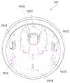
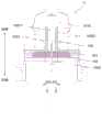
图1为本发明实施例分析物检测装置安装单元的外部结构示意图。安装单元100的外部结构包括壳体101和保护盖102,壳体101用于承载内部结构件。安装单元100在使用时,靠近用户皮肤的一端为近端,远离皮肤的一端为远端。在壳体101的近端方向设置有第一开口。保护盖102用于对壳体101的内部结构和内部结构件进行保护、密封以及防触发。FIG. 1 is a schematic diagram of the external structure of an installation unit of an analyte detection device according to an embodiment of the present invention. The external structure of the
壳体外部Shell exterior
图2a为本发明实施例壳体的外部结构示意图,图2b为保护盖的结构示意图。保护盖102包括外盖体1021、卡箍1022和内盖体1023。外盖体1021远端方向设置有第二开口,第二开口面向第一开口。在第二开口,外盖体1021与卡箍1022通过可折断的立柱10211连接,立柱10211按一定的间距分布在外盖体1021和卡箍1022之间。外盖体1021相对于卡箍1022旋转时,立柱10211可被折断,外盖体1021与卡箍1022分离。Fig. 2a is a schematic diagram of the external structure of the housing according to the embodiment of the present invention, and Fig. 2b is a schematic diagram of the structure of the protective cover. The
外盖体1021内侧设置有内螺纹10212,对应的,内盖体1023外侧设置有外螺纹10231,内螺纹10212与外螺纹10231可配合连接,以将外盖体1021与内盖体1023连接在一起并保持固定。The inner side of the
卡箍1022内侧设置有凸起10221,对应的,壳体101的外侧设置有凹槽1011,凹槽1011环绕于壳体外侧形成圆周,凸起10221可嵌入凹槽1011内。外盖体1021先与内盖体1023通过螺纹配合固定后,再通过卡箍1022与壳体101连接,外盖体1021和内盖体1023可对壳体101的内部结构进行保护、密封以及防触发,这里防触发功能将在下文中进一步阐述。The inner side of the
在本发明其他实施例中,外盖体1021与内盖体1023之间也可以摩擦配合或者卡扣配合实现固定连接。In other embodiments of the present invention, the
在本发明其他实施例中,卡箍1022与壳体101之间也可以通过摩擦配合、卡扣配合或者螺纹配合实现连接。In other embodiments of the present invention, the connection between the
壳体内部Inside the shell
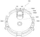
图3为本发明实施例分析物检测装置安装单元的爆炸结构示意图,图中虚线表示各结构件的安装配合关系。分析物检测装置安装单元100的内部结构件包括平行滑块模块103、分析物检测装置104、辅助针模块105、触发模块106和弹性模块107,弹性模块107包括第一弹性件1071和第二弹性件1072。FIG. 3 is a schematic diagram of an exploded structure of an installation unit of an analyte detection device according to an embodiment of the present invention. The dotted lines in the figure indicate the installation and coordination relationship of various structural components. The internal structure of the analyte detection
图4为本发明实施例壳体101的内部结构示意图。FIG. 4 is a schematic diagram of the internal structure of the
在本发明实施例中,壳体101内设置有至少两个第一卡扣1012,第一卡扣1012与壳体101一体成型,并向壳体101的近端凸出。第一卡扣1012为柔性材料,末端可向壳体101的外侧弯折或者弯曲。In the embodiment of the present invention, at least two
在本发明优选实施例中,第一卡扣1012的数量为两个,对称分布在壳体101内部,彼此间的角度间隔为180°。In a preferred embodiment of the present invention, there are two
在本发明其他优选实施例中,第一卡扣1012的数量为三个或者四个,对称分布在壳体101内部,彼此间的角度间隔为120°或者90°。第一卡扣1012的数量也可以是五个或者更多,在此不作限制。In other preferred embodiments of the present invention, the number of the
在本发明实施例中,壳体101内还设置有至少两个限位槽1013、至少两个卡槽1014以及一个辅助针限位槽1015。In the embodiment of the present invention, at least two limiting
在本发明实施例中,限位槽1013包括至少两条凸出于壳体101内壁的肋板。在本发明优选实施例中,肋板彼此平行,相邻的肋板中间形成凹槽。In the embodiment of the present invention, the limiting
在本发明其他实施例中,限位槽1013为凹陷于壳体101内壁的槽。In other embodiments of the present invention, the limiting
在本发明实施例中,卡槽1014包括两个卡槽位,即第一卡槽位10141和第二卡槽位10142,如图10a所示,第一卡槽位10141相对于第二卡槽位10142靠近于近端。In the embodiment of the present invention, the
在本发明优选实施例中,限位槽1013、卡槽1014的数量为两个,对称分布在壳体101内部,彼此间的角度间隔为180°。In a preferred embodiment of the present invention, there are two limiting
在本发明其他优选实施例中,限位槽1013、卡槽1014的数量为三个或者四个,对称分布在壳体101内部,彼此间的角度间隔为120°或者90°。限位槽1013、卡槽1014的数量也可以是五个或者更多,在此不作限制。In other preferred embodiments of the present invention, the number of limiting
平行滑块模块Parallel Slider Module
图5a为平行滑块模块103远端面的结构示意图,图5b为平行滑块模块103近端面的结构示意图。FIG. 5 a is a schematic structural diagram of the distal surface of the
在本发明实施例中,平行滑块模块103的远端面1031设置有向远端凸起的圆形槽1032,圆形槽1032为内部掏空的圆柱结构,其内径为d1。在圆形槽1032的侧壁上向远端伸出至少两个滑块卡扣10321,滑块卡扣10321的卡扣部为平面或者近似平面,并与水平面呈固定夹角,其延长端m0汇聚在远端。In the embodiment of the present invention, the
在本发明实施例中,滑块卡扣10321为柔性材料,因此可向圆形槽1032的外侧弯曲或者弯折。In the embodiment of the present invention, the
在本发明其他实施例中,滑块卡扣10321可直接设置在平行滑块模块103的远端面,而不需要圆形槽结构。In other embodiments of the present invention, the
在本发明实施例中,圆形槽1032内靠近远端面1031的一端还设置有一段凸台10322,凸台10322为内部掏空的圆柱体结构,其内径为d2,可以理解的是d1>d2。内部掏空结构的圆形槽1032和凸台10322形成一个通孔10323,从平行滑块模块的远端面1031贯穿到近端面1034。In the embodiment of the present invention, a
在本发明优选实施例中,滑块卡扣10321的数量为两个,对称分布在圆形槽1032的侧壁上,两个滑块卡扣10321彼此间的角度间隔为180°。In a preferred embodiment of the present invention, there are two slider buckles 10321, which are symmetrically distributed on the side wall of the
在本发明其他优选实施例中,滑块卡扣10321的数量可以为三个或者四个,对称分布在圆形槽1032的侧壁上,滑块卡扣10321彼此间的角度间隔为120°或者90°。滑块卡扣10321的数量也可以是五个或者更多,在此不作限制。In other preferred embodiments of the present invention, the number of slider buckles 10321 can be three or four, symmetrically distributed on the side wall of the
继续参照图5a,在本发明实施例中,平行滑块模块103的远端面1031侧边设置有至少两个第二卡扣1033,第二卡扣1033对称分布在远端面1031侧边,彼此间的角度间隔为180°。Continuing to refer to FIG. 5 a , in an embodiment of the present invention, at least two
在本发明其他实施例中,第二卡扣1033的数量为三个或者四个,对称分布在远端面1031侧边,彼此间的角度间隔为120°或者90°。第二卡扣1033的数量也可以是五个或者更多,在此不做限制。在安装单元100中,第二卡扣1033与第一卡扣1012耦合。第二卡扣1033的位置和数量与第一卡扣1012一致。In other embodiments of the present invention, the number of the
参照图5b,在本发明实施例中,平行滑块模块103的近端面1034侧边设置有至少两个T型结构1035,T型结构1035的竖直部连接于近端面1034,水平部包括T型结构滑块10351和T型结构卡扣10352,T型结构滑块10351朝向平行滑块模块103的外侧,并且凸出于平行滑块模块103的外圈;T型结构卡扣10352朝向平行滑块模块103的内侧,并且凸出于平行滑块模块103的内圈。Referring to Fig. 5b, in an embodiment of the present invention, at least two T-shaped
在安装单元100中,T型结构滑块10351位于限位槽1013内,以限制平行滑块模块103的位置,并防止平行滑块模块103在安装单元100内发生转动。T型结构滑块10351的数量及位置与限位槽1013一致。平行滑块模块103向近端运动过程中,T型结构滑块10351在限位槽1013内滑动。In the
在本发明优选实施例中,T型结构1035的竖直部为柔性材料,竖直部与水平部一体成型,水平部可绕竖直部弯折或者弯曲。In a preferred embodiment of the present invention, the vertical part of the T-shaped
在本发明其他优选实施例中,T型结构1035的竖直部为弹性材料,例如弹簧、弹片等,水平部通过焊接或者热熔等工艺与竖直部固定连接,水平部也可绕竖直部弯折或者弯曲。In other preferred embodiments of the present invention, the vertical part of the T-shaped
分析物检测装置Analyte detection device
图6为本发明实施例分析物检测装置的结构示意图。Fig. 6 is a schematic structural diagram of an analyte detection device according to an embodiment of the present invention.
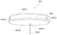
结合参照图3,在本发明实施例中,分析物检测装置104包括外壳1041、发射器(图中未示出)、传感器1042和设置在外壳1041内并与传感器电耦合的内部电路(图中未示出)。传感器1042用于检测用户体液分析物参数信息,通过内部电路将上述分析物参数信息传递至发射器,再由发射器发送至外界设备200。3, in an embodiment of the present invention, the
在本发明优选实施例中,在分析物检测装置104安装到用户皮肤表面前,以第一频率f1向外界设备200发射信号,安装到用户皮肤表面后,以第二频率f2向外界设备200发射信号,第二频率f2大于第一频率f1。在本发明进一步优选实施例中,第一频率f1为0~12次/小时,第二频率f2为12~3600次/小时。In a preferred embodiment of the present invention, before the
在本发明更优选实施例中,第一频率f1为0次/小时,即在分析物检测装置104安装到用户皮肤表面前,不向外界设备200发射信号,这样可以节省安装前分析物检测装置104的电量消耗。In a more preferred embodiment of the present invention, the first frequency f1 is 0 times/hour, that is, before the
在本发明实施例中,外壳1041包括上外壳体10411和下外壳体10413,上外壳体10411和下外壳体10413拼接形成内部空间。传感器1042包括体外部分(图中未示出)和体内部分(图中未示出),体外部分、发射器和内部电路设置在内部空间中,体外部分与内部电路电耦合。体内部分上设置有电极、膜层等结构,刺入用户皮下可以对分析物参数信息进行检测。体内部分刺入皮下时,需要有正确的角度,例如垂直于皮肤表面刺入。在分析物检测装置104寿命终止后,将其从用户皮肤表面取下,整体抛弃。In the embodiment of the present invention, the
在本发明实施例中,下外壳体10413包括贯穿的第一通孔10414,对应的,在第一通孔10414的轴线上,上外壳体10411包括贯穿的第二通孔(图中未示出),体内部分穿过第一通孔10414到外壳外部,以便于刺入用户皮下。In the embodiment of the present invention, the
在本发明实施例中,上外壳体10411的侧边包括对应于T型结构卡扣10352的卡孔10412,这里“对应”是指卡孔10412的位置、数量与T型结构卡扣10352一致。在安装单元100中,上外壳体10411与近端面1034贴合,T型结构卡扣10352与卡孔10412形成卡扣连接,分析物检测装置104被固定在平行滑块模块103上。当T型结构的水平部绕竖直部弯折或者弯曲时,T型结构卡扣10352与卡孔10412的卡扣连接解除,分析物检测装置104与平行滑块模块103分离。因此在安装单元100中,分析物检测装置104与平行滑块模块103为可释放连接。In the embodiment of the present invention, the side of the
辅助针模块Auxiliary Needle Module
图7为本发明实施例辅助针模块的结构示意图。Fig. 7 is a schematic structural diagram of an auxiliary needle module according to an embodiment of the present invention.
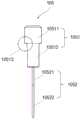
在本发明实施例中,辅助针模块105包括辅助针固定结构1051和辅助针1052。在安装单元100中,辅助针固定结构1051位于远端,辅助针1052位于近端。In the embodiment of the present invention, the
在本发明实施例中,辅助针固定结构1051包括辅助针滑块10511和辅助针固定块10512,辅助针滑块10511的直径或者宽度大于辅助针固定块10512的直径或者宽度,形成一个朝向近端的凸面10513。In the embodiment of the present invention, the auxiliary
在本发明实施例中,辅助针1052包括全包围针体10521和半包围针体10522,全包围针体10521位于辅助针固定块10512和半包围针体10522之间,并与辅助针固定块10512固定连接。半包围针体10522的中空结构可用于容纳传感器1042的体内部分,半包围针体10522刺入用户皮下时,可将体内部分一并刺入皮下,并且在针体缩回时,不影响体内部分在皮下的状态。In the embodiment of the present invention, the
在本发明其他实施例中,辅助针1052仅包括半包围针体10522,即半包围针体10522与辅助针固定块10512固定连接,这样可以减少辅助针1052的用料,节省成本,但同时也减小了辅助针1052的刚性。In other embodiments of the present invention, the
在安装单元100中,辅助针1052依次穿过第二通孔和第一通孔10414,从而贯穿分析物检测装置104,传感器1042的体内部分位于半包围针体10522中。In the
触发模块trigger module
图8为本发明实施例触发模块的结构示意图。FIG. 8 is a schematic structural diagram of a trigger module according to an embodiment of the present invention.
在本发明实施例中,触发模块106上设置有至少两个与第一卡扣1012对应的固定卡扣1061。在安装单元100中,固定卡扣1061与第一卡扣1012接触,以阻止第一卡扣1012向壳体外侧弯曲或者弯折。固定卡扣1061与第一卡扣1012的接触可以是点接触、线接触或者面接触,当接触为面接触时,固定卡扣1061与第一卡扣1012接触面与水平面呈固定夹角,并汇聚在安装单元100的近端。固定卡扣1061的数量及位置与第一卡扣1012一致。In the embodiment of the present invention, the
在本发明实施例中,触发模块106上还设置有至少两个卡耳1062,在安装单元100中,卡耳1062与卡槽1014卡扣配合,以固定触发模块106。卡耳1062的数量及位置与卡槽1014一致。结合参照图10a,在安装单元100使用前,卡耳1062位于第一卡槽位10141,此时,固定卡扣1061与第一卡扣1012接触。In the embodiment of the present invention, at least two
在本发明实施例中,触发模块106还包括一个外圈1063,外圈1063将上述固定卡扣1061和卡耳1062连接成一个整体。在安装单元100中,外圈1063相对于卡耳1062靠近于近端,位于第一开口且凸出于第一开口,在使用安装单元100时,外圈1063贴合用户皮肤表面。In the embodiment of the present invention, the
弹性模块Elastic module
参照图3,弹性模块107包括第一弹性件1071和第二弹性件1072。Referring to FIG. 3 , the
在本发明实施例中,第一弹性件1071位于平行滑块模块103和壳体101之间,即第一弹性件1071的一端位于平行滑块模块103的远端面,另一端位于壳体101内,在安装单元100中,第一弹性件1071处于压缩状态,可提供弹力。In the embodiment of the present invention, the first
在本发明实施例中,第二弹性件1072位于平行滑块模块103和辅助针模块105之间,即第二弹性件1072的一端位于平行滑块模块103的凸台10322上,另一端位于辅助针模块105的凸面10513上,在安装单元100中,第二弹性件1072处于压缩状态,可提供弹力。In the embodiment of the present invention, the second
在本发明优选实施例中,第一弹性件1071或者第二弹性件1072为金属弹簧。In a preferred embodiment of the present invention, the first
在本发明实施例中,第一弹性件1071的内圈直径大于圆形槽1032和辅助针滑块10511的外圈直径,在安装单元100中,第一弹性件1071包围在辅助针滑块10511和圆形槽1032外侧,可以充分利用安装单元100的内部空间。In the embodiment of the present invention, the diameter of the inner ring of the first
在本发明实施例中,第二弹性件1072的外圈直径大于辅助针固定块10512的外径和凸台10322的内径,而小于辅助针滑块10511的外径和圆形槽1032的内径,因此第二弹性件1072的一端放置在圆形槽1032内,另一端包围在辅助针固定块10512外侧,可以充分利用安装单元100的内部空间。In the embodiment of the present invention, the outer diameter of the second
安装单元使用方法How to use the installation unit
图9为本发明实施例安装单元的俯视图。Fig. 9 is a top view of the installation unit according to the embodiment of the present invention.
图10a为图9的A剖面结构示意图;图10b为图9的B剖面结构示意图;图10c为图9的C剖面结构示意图;图11为第一卡扣受力弯折示意图。10a is a schematic diagram of the cross-sectional structure of FIG. 9; FIG. 10b is a schematic diagram of the cross-sectional structure of FIG. 9; FIG. 10c is a schematic diagram of the cross-sectional structure of FIG. 9; FIG.
结合参照图10a和图10b,在本发明实施例中,卡槽1014设置有两个卡槽位,第一卡槽位10141和第二卡槽位10142。在安装单元100使用前,触发模块106通过卡耳1062与第一卡槽位10141的卡扣配合固定在壳体101上,此时,固定卡扣1061与第一卡扣1012接触,阻止第一卡扣1012向壳体101外侧弯曲或者弯折,固定卡扣1061、第一卡扣1012和第二卡扣1033位于同一水平线上。在本发明优选实施例中,由壳体101内向外,依次为第二卡扣1033、第一卡扣1012和固定卡扣1061。Referring to FIG. 10 a and FIG. 10 b together, in the embodiment of the present invention, the
在本发明实施例中,固定卡扣1061与第一卡扣1012的接触为点接触、线接触或者面接触中的一种,当上述接触为面接触时,接触面的延长线m1汇聚在近端,这种结构设计可以使得固定卡扣1061相对于第一卡扣1012向远端运动。In the embodiment of the present invention, the contact between the fixed
在本发明优选实施例中,第二卡扣1033与第一卡扣1012的耦合面为平面,该平面与水平面呈固定夹角,其延长端m2汇聚在近端。In a preferred embodiment of the present invention, the coupling surface of the
结合参照图11,这种结构设计可以使得第二卡扣1033相对于第一卡扣1012向近端运动时,将第一卡扣1012向壳体101外侧推开,从而解除第一卡扣1012与第二卡扣1033间的耦合状态。Referring to FIG. 11 , this structural design can push the
在本发明实施例中,第一弹性件1071处于压缩状态,具备弹性势能,其自身弹力给予平行模块滑块103向近端的推力Fr,该推力Fr通过第二卡扣1033和第一卡扣1012的耦合面作用在第一卡扣1012上,并产生垂直于第一卡扣1012平面的分力Fsin,该分力Fsin可将第一卡扣1012向壳体101外侧推动而弯曲或者弯折,从而解除第一卡扣1012与第二卡扣1033的耦合状态。In the embodiment of the present invention, the first
在本发明实施例中,使用安装单元100时,旋转外盖体1021,使立柱10211折断,保护盖102与壳体101分离,将安装单元100的近端靠近用户皮肤,直到触发模块106的外圈1063贴合在皮肤表面,用户在远端按压壳体101,壳体101朝向皮肤运动,触发模块106保持不动,因此触发模块106相对于壳体101向远端运动,卡耳1062脱离第一卡槽位10141,进入到第二卡槽位10142,同时固定卡扣1061不再与第一卡扣1012接触,第一卡扣1012因分力Fsin向壳体101外侧弯曲或者弯折,第一卡扣1012与第二卡扣1033的耦合状态解除。In the embodiment of the present invention, when using the
在本发明实施例中,解除耦合状态后,平行滑块模块103在第一弹性件1071的弹力推动下继续向近端运动,同时带动分析物检测装置104向近端运动,直至分析物检测装置104的下外壳体10413与用户皮肤表面接触。In the embodiment of the present invention, after the coupling state is released, the
参照图10c,在本发明实施例中,滑块卡扣10321与辅助针滑块10511卡扣连接,第一弹性件1071推动平行滑块模块103向近端运动时,带动辅助针模块105一起向近端运动。Referring to Fig. 10c, in the embodiment of the present invention, the
在本发明实施例中,滑块卡扣10321与辅助针滑块10511的连接处为平面或者近似平面,该平面与水平面呈固定夹角,其延长线m3汇聚在远端。第二弹性件1072对辅助针滑块10511的推力朝向远端,因此辅助针滑块10511可将滑块卡扣10321向壳体101外侧推开,而使得滑块卡扣10321发生弯曲或者弯折,其原理等同于图11。In the embodiment of the present invention, the connection between the
在本发明实施例中,在安装单元100中,辅助针限位槽1015的侧壁阻止滑块卡扣10321发生弯折或者弯曲,滑块卡扣10321与辅助针滑块10511卡扣连接状态不发生变化。随着平行滑块模块103和辅助针模块105向近端运动,直到滑块卡扣10321脱离辅助针限位槽1015,辅助针限位槽1015的内壁不再阻止滑块卡扣10321发生弯折或者弯曲,第二弹性件1072向远端推动辅助针滑块10511,同时辅助针滑块10511推动滑块卡扣10321向外侧弯折或者弯曲,滑块卡扣10321与辅助针滑块10511的卡扣连接解除,第二弹性件1072继续推动辅助针滑块10511向远端运动,最终辅助针模块105回到初始位置,辅助针1052缩回到壳体101内,防止辅助针1052暴露在壳体101外面,避免造成不必要的伤害。In the embodiment of the present invention, in the
在本发明实施例中,滑块卡扣10321脱离辅助针限位槽1015时,辅助针的半包围针体10522刺入用户皮下。In the embodiment of the present invention, when the
在本发明实施例中,在安装单元100中,T型结构滑块10351位于限位槽1013内,限位槽1013通过T型结构滑块10351对平行滑块模块103的位置、方向进行限制,以保证平行滑块模块103与其滑动方向保持垂直,从而使设置在平行滑块模块103前端的分析物检测装置104与其运动方向保持垂直,同时辅助针1052与其运动方向保持平行,这样可以使辅助针1052及其包络的传感器体内部分以垂直角度刺入用户皮下,减轻用户的疼痛感。In the embodiment of the present invention, in the
在本发明实施例中,在平行滑块模块103向近端滑动过程中,T型结构滑块10351在限位槽1013内滑动,直至接触到触发模块106的外圈1063,在第一弹性件1071的推动下,平行滑块模块103继续向近端运动,而外圈1063阻挡T型结构滑块10351继续向近端运动,因此T型结构滑块10351绕竖直部弯曲或者弯折,T型结构卡扣10352与卡孔10412的卡扣连接解除,分析物检测装置104脱离平行滑块模块103,从而可以安装在用户皮肤表面。In the embodiment of the present invention, when the
在本发明实施例中,T型结构滑块10351与外圈1063接触时,平行滑块模块103所处的位置为预定位置,此时,分析物检测装置的下外壳体10413与用户皮肤表面接触。In the embodiment of the present invention, when the T-shaped
在本发明实施例中,辅助针1052依次穿过第二通孔和第一通孔10414,而贯穿分析物检测装置104,同时,辅助针的半包围针体10522包络传感器1042。在平行滑块模块103和辅助针模块105向近端运动过程中,半包围针体10522携带传感器1042刺入皮下,辅助针1052缩回后,传感器1042体内部分保持在皮下,针体缩回时不影响传感器1042体内部分所处状态。In the embodiment of the present invention, the
在本发明实施例中,实施安装动作时,需要用户在远端按压壳体101,向壳体101施加向近端的力F,触发模块106的外圈1063接触用户皮肤表面,用户皮肤给予外圈1063与力F反向的力F’,从而实现触发模块106与壳体101的相对运动。在实际安装过程中,触发模块106的绝对位置保持不变,壳体101向近端运动。In the embodiment of the present invention, when performing the installation action, the user needs to press the
在实施安装动作之前,为防止触发模块106相对于壳体101发生运动,在壳体101的近端安装保护盖102,保护盖102包围在触发模块的外圈1063外侧,可以防止因误碰外圈1063而在不正确的位置实施安装动作,起到防触发的作用。Before implementing the installation action, in order to prevent the
内盖体1023的远端面10232与分析物检测装置104接触,同时辅助针1052和传感器1042伸入到内盖体凹槽10233,可以起到密封的作用,防止外界灰尘、颗粒等脏污与针体和传感器接触,造成污染。The
在本发明实施例中,分析物检测装置的下外壳体10413上还设置有胶布(图中未示出),用于将分析物检测装置104固定在用户皮肤表面。In the embodiment of the present invention, an adhesive plaster (not shown in the figure) is also provided on the lower
综上所述,本发明实施例公开了一种分析物检测装置安装单元,壳体上设置有限位槽,对应的,平行滑块模块上设置有T型结构滑块,T型结构滑块位于限位槽内,实施安装动作时,T型结构滑块在限位槽内滑动。T型结构滑块与限位槽的配合,可以对平行滑块模块起到限位作用,避免平行滑块模块在壳体内发生偏转,引导平行滑块模块在壳体内滑动,从而使传感器以垂直的方向刺入皮下,安装单元结构简单,便于使用。To sum up, the embodiment of the present invention discloses an installation unit for an analyte detection device. The casing is provided with a limiting slot. Correspondingly, the parallel slider module is provided with a T-shaped structural slider, and the T-shaped structural slider is located on the In the limit groove, when the installation action is implemented, the T-shaped structure slider slides in the limit groove. The cooperation between the T-shaped structure slider and the limit groove can limit the position of the parallel slider module, avoid the deflection of the parallel slider module in the housing, and guide the parallel slider module to slide in the housing, so that the sensor can be vertical The direction of piercing into the skin, the installation unit has a simple structure and is easy to use.
虽然已经通过示例对本发明的一些特定实施例进行了详细说明,但是本领域的技术人员应该理解,以上示例仅是为了进行说明,而不是为了限制本发明的范围。本领域的技术人员应该理解,可在不脱离本发明的范围和精神的情况下,对以上实施例进行修改。本发明的范围由所附权利要求来限定。Although some specific embodiments of the present invention have been described in detail through examples, those skilled in the art should understand that the above examples are for illustration only, rather than limiting the scope of the present invention. Those skilled in the art will appreciate that modifications can be made to the above embodiments without departing from the scope and spirit of the invention. The scope of the invention is defined by the appended claims.
Claims (14)
Translated fromChinesePriority Applications (1)
| Application Number | Priority Date | Filing Date | Title |
|---|---|---|---|
| CN202111135558.7ACN115868970A (en) | 2021-09-27 | 2021-09-27 | Analyte detection device installation unit |
Applications Claiming Priority (1)
| Application Number | Priority Date | Filing Date | Title |
|---|---|---|---|
| CN202111135558.7ACN115868970A (en) | 2021-09-27 | 2021-09-27 | Analyte detection device installation unit |
Publications (1)
| Publication Number | Publication Date |
|---|---|
| CN115868970Atrue CN115868970A (en) | 2023-03-31 |
Family
ID=85762938
Family Applications (1)
| Application Number | Title | Priority Date | Filing Date |
|---|---|---|---|
| CN202111135558.7APendingCN115868970A (en) | 2021-09-27 | 2021-09-27 | Analyte detection device installation unit |
Country Status (1)
| Country | Link |
|---|---|
| CN (1) | CN115868970A (en) |
Citations (6)
| Publication number | Priority date | Publication date | Assignee | Title |
|---|---|---|---|---|
| CN102307518A (en)* | 2009-02-03 | 2012-01-04 | 雅培糖尿病护理公司 | Analyte sensors and devices for sensor insertion |
| CN104302333A (en)* | 2012-04-11 | 2015-01-21 | 法玛森斯股份公司 | Subcutaneous needle insertion mechanism |
| CN106137214A (en)* | 2016-08-12 | 2016-11-23 | 上海移宇科技股份有限公司 | A kind of transcutaneous analyte sensing equipment and installation method thereof |
| WO2018222012A1 (en)* | 2017-06-02 | 2018-12-06 | 주식회사 아이센스 | Sensor applicator assembly for continuous glucose monitoring system |
| CN209421928U (en)* | 2018-08-29 | 2019-09-24 | 深圳市小雨智能科技养生有限公司 | A kind of human body electrophysiologicalsignal signal detection instrument |
| CN218247218U (en)* | 2021-09-27 | 2023-01-10 | 上海移宇科技股份有限公司 | Analyte detection device installation unit |
- 2021
- 2021-09-27CNCN202111135558.7Apatent/CN115868970A/enactivePending
Patent Citations (6)
| Publication number | Priority date | Publication date | Assignee | Title |
|---|---|---|---|---|
| CN102307518A (en)* | 2009-02-03 | 2012-01-04 | 雅培糖尿病护理公司 | Analyte sensors and devices for sensor insertion |
| CN104302333A (en)* | 2012-04-11 | 2015-01-21 | 法玛森斯股份公司 | Subcutaneous needle insertion mechanism |
| CN106137214A (en)* | 2016-08-12 | 2016-11-23 | 上海移宇科技股份有限公司 | A kind of transcutaneous analyte sensing equipment and installation method thereof |
| WO2018222012A1 (en)* | 2017-06-02 | 2018-12-06 | 주식회사 아이센스 | Sensor applicator assembly for continuous glucose monitoring system |
| CN209421928U (en)* | 2018-08-29 | 2019-09-24 | 深圳市小雨智能科技养生有限公司 | A kind of human body electrophysiologicalsignal signal detection instrument |
| CN218247218U (en)* | 2021-09-27 | 2023-01-10 | 上海移宇科技股份有限公司 | Analyte detection device installation unit |
Similar Documents
| Publication | Publication Date | Title |
|---|---|---|
| CN216257100U (en) | Analyte Detection Device Mounting Unit | |
| CN216495287U (en) | Analyte detection device mounting unit | |
| CN216652295U (en) | Analyte detection device mounting unit | |
| CN215959882U (en) | Analyte Detection Device Mounting Unit | |
| CN110664415B (en) | Application device | |
| CN115868971A (en) | Analyte detection device mounting unit and method of use thereof | |
| WO2022007537A1 (en) | Installation unit of analyte detection device | |
| CN218247218U (en) | Analyte detection device installation unit | |
| CN115919301A (en) | Analyte detection device installation unit | |
| CN115868973A (en) | Analyte detection device installation unit | |
| WO2023046154A1 (en) | Analyte sensor fixing device | |
| US20240389892A1 (en) | Installation unit of analyte detection device | |
| CN115868970A (en) | Analyte detection device installation unit | |
| CN115868972A (en) | Analyte detection device installation unit | |
| WO2023044893A1 (en) | Installation unit of analyte detection device | |
| WO2023044888A1 (en) | Installation unit of analyte detection device | |
| CN115868976A (en) | Analyte detection device mounting unit | |
| CN118986342B (en) | Secure Analyte Detection Device Installation Unit | |
| CN118986341B (en) | Analyte detection device installation unit with protective structure | |
| CN223350207U (en) | Secure analyte detection device mounting unit | |
| CN118948266B (en) | Secure analyte detection device mounting unit | |
| CN223350208U (en) | Analyte detection device mounting unit with protective structure | |
| CN216417179U (en) | Last needle structure on blood sugar detector | |
| CN219207039U (en) | Analyte Sensor Fixture | |
| CN216417181U (en) | Blood sugar detector and push pin brake switch on same |
Legal Events
| Date | Code | Title | Description |
|---|---|---|---|
| PB01 | Publication | ||
| PB01 | Publication | ||
| SE01 | Entry into force of request for substantive examination | ||
| SE01 | Entry into force of request for substantive examination |