CN115864609A - Electronic equipment and charging method - Google Patents
Electronic equipment and charging methodDownload PDFInfo
- Publication number
- CN115864609A CN115864609ACN202310157759.XACN202310157759ACN115864609ACN 115864609 ACN115864609 ACN 115864609ACN 202310157759 ACN202310157759 ACN 202310157759ACN 115864609 ACN115864609 ACN 115864609A
- Authority
- CN
- China
- Prior art keywords
- module
- charging
- controller
- switch
- diode
- Prior art date
- Legal status (The legal status is an assumption and is not a legal conclusion. Google has not performed a legal analysis and makes no representation as to the accuracy of the status listed.)
- Granted
Links
Images


Classifications
- H—ELECTRICITY
- H02—GENERATION; CONVERSION OR DISTRIBUTION OF ELECTRIC POWER
- H02J—CIRCUIT ARRANGEMENTS OR SYSTEMS FOR SUPPLYING OR DISTRIBUTING ELECTRIC POWER; SYSTEMS FOR STORING ELECTRIC ENERGY
- H02J7/00—Circuit arrangements for charging or depolarising batteries or for supplying loads from batteries
- H02J7/0013—Circuit arrangements for charging or depolarising batteries or for supplying loads from batteries acting upon several batteries simultaneously or sequentially
- H—ELECTRICITY
- H01—ELECTRIC ELEMENTS
- H01M—PROCESSES OR MEANS, e.g. BATTERIES, FOR THE DIRECT CONVERSION OF CHEMICAL ENERGY INTO ELECTRICAL ENERGY
- H01M10/00—Secondary cells; Manufacture thereof
- H01M10/42—Methods or arrangements for servicing or maintenance of secondary cells or secondary half-cells
- H01M10/44—Methods for charging or discharging
- H01M10/441—Methods for charging or discharging for several batteries or cells simultaneously or sequentially
- H—ELECTRICITY
- H02—GENERATION; CONVERSION OR DISTRIBUTION OF ELECTRIC POWER
- H02J—CIRCUIT ARRANGEMENTS OR SYSTEMS FOR SUPPLYING OR DISTRIBUTING ELECTRIC POWER; SYSTEMS FOR STORING ELECTRIC ENERGY
- H02J7/00—Circuit arrangements for charging or depolarising batteries or for supplying loads from batteries
- H02J7/00032—Circuit arrangements for charging or depolarising batteries or for supplying loads from batteries characterised by data exchange
- H02J7/00036—Charger exchanging data with battery
- H—ELECTRICITY
- H02—GENERATION; CONVERSION OR DISTRIBUTION OF ELECTRIC POWER
- H02J—CIRCUIT ARRANGEMENTS OR SYSTEMS FOR SUPPLYING OR DISTRIBUTING ELECTRIC POWER; SYSTEMS FOR STORING ELECTRIC ENERGY
- H02J7/00—Circuit arrangements for charging or depolarising batteries or for supplying loads from batteries
- H02J7/0029—Circuit arrangements for charging or depolarising batteries or for supplying loads from batteries with safety or protection devices or circuits
- H02J7/00304—Overcurrent protection
- H—ELECTRICITY
- H02—GENERATION; CONVERSION OR DISTRIBUTION OF ELECTRIC POWER
- H02J—CIRCUIT ARRANGEMENTS OR SYSTEMS FOR SUPPLYING OR DISTRIBUTING ELECTRIC POWER; SYSTEMS FOR STORING ELECTRIC ENERGY
- H02J7/00—Circuit arrangements for charging or depolarising batteries or for supplying loads from batteries
- H02J7/0029—Circuit arrangements for charging or depolarising batteries or for supplying loads from batteries with safety or protection devices or circuits
- H02J7/00308—Overvoltage protection
- H—ELECTRICITY
- H02—GENERATION; CONVERSION OR DISTRIBUTION OF ELECTRIC POWER
- H02J—CIRCUIT ARRANGEMENTS OR SYSTEMS FOR SUPPLYING OR DISTRIBUTING ELECTRIC POWER; SYSTEMS FOR STORING ELECTRIC ENERGY
- H02J7/00—Circuit arrangements for charging or depolarising batteries or for supplying loads from batteries
- H02J7/0047—Circuit arrangements for charging or depolarising batteries or for supplying loads from batteries with monitoring or indicating devices or circuits
- H—ELECTRICITY
- H02—GENERATION; CONVERSION OR DISTRIBUTION OF ELECTRIC POWER
- H02J—CIRCUIT ARRANGEMENTS OR SYSTEMS FOR SUPPLYING OR DISTRIBUTING ELECTRIC POWER; SYSTEMS FOR STORING ELECTRIC ENERGY
- H02J7/00—Circuit arrangements for charging or depolarising batteries or for supplying loads from batteries
- H02J7/0068—Battery or charger load switching, e.g. concurrent charging and load supply
- H—ELECTRICITY
- H02—GENERATION; CONVERSION OR DISTRIBUTION OF ELECTRIC POWER
- H02J—CIRCUIT ARRANGEMENTS OR SYSTEMS FOR SUPPLYING OR DISTRIBUTING ELECTRIC POWER; SYSTEMS FOR STORING ELECTRIC ENERGY
- H02J7/00—Circuit arrangements for charging or depolarising batteries or for supplying loads from batteries
- H02J7/007—Regulation of charging or discharging current or voltage
- H02J7/00712—Regulation of charging or discharging current or voltage the cycle being controlled or terminated in response to electric parameters
- H02J7/00714—Regulation of charging or discharging current or voltage the cycle being controlled or terminated in response to electric parameters in response to battery charging or discharging current
- H—ELECTRICITY
- H02—GENERATION; CONVERSION OR DISTRIBUTION OF ELECTRIC POWER
- H02J—CIRCUIT ARRANGEMENTS OR SYSTEMS FOR SUPPLYING OR DISTRIBUTING ELECTRIC POWER; SYSTEMS FOR STORING ELECTRIC ENERGY
- H02J2207/00—Indexing scheme relating to details of circuit arrangements for charging or depolarising batteries or for supplying loads from batteries
- H02J2207/30—Charge provided using DC bus or data bus of a computer
- Y—GENERAL TAGGING OF NEW TECHNOLOGICAL DEVELOPMENTS; GENERAL TAGGING OF CROSS-SECTIONAL TECHNOLOGIES SPANNING OVER SEVERAL SECTIONS OF THE IPC; TECHNICAL SUBJECTS COVERED BY FORMER USPC CROSS-REFERENCE ART COLLECTIONS [XRACs] AND DIGESTS
- Y02—TECHNOLOGIES OR APPLICATIONS FOR MITIGATION OR ADAPTATION AGAINST CLIMATE CHANGE
- Y02E—REDUCTION OF GREENHOUSE GAS [GHG] EMISSIONS, RELATED TO ENERGY GENERATION, TRANSMISSION OR DISTRIBUTION
- Y02E60/00—Enabling technologies; Technologies with a potential or indirect contribution to GHG emissions mitigation
- Y02E60/10—Energy storage using batteries
Landscapes
- Engineering & Computer Science (AREA)
- Power Engineering (AREA)
- Manufacturing & Machinery (AREA)
- Chemical & Material Sciences (AREA)
- Chemical Kinetics & Catalysis (AREA)
- Electrochemistry (AREA)
- General Chemical & Material Sciences (AREA)
- Charge And Discharge Circuits For Batteries Or The Like (AREA)
- Secondary Cells (AREA)
Abstract
Description
Translated fromChinese技术领域technical field
本申请涉及终端技术领域,尤其涉及一种电子设备及充电方法。The present application relates to the technical field of terminals, and in particular to an electronic device and a charging method.
背景技术Background technique
目前的台式机(Desktop)、一体机以及笔记本电脑(Notebook或Laptop)等个人计算机(personal computer,PC)产品一般包括至少两个通用串行总线(Universal SerialBus,USB) Type-C接口,以下简称Type-C接口。PC可以利用Type-C接口进行充电或者对其他电子设备充电。Current personal computer (PC) products such as desktops, all-in-ones, and notebooks (Notebook or Laptop) generally include at least two Universal Serial Bus (USB) Type-C interfaces, hereinafter referred to as Type-C interface. The PC can use the Type-C interface to charge or charge other electronic devices.
目前,PC产品的Type-C接口支持USB功率传输(Power Delivery,PD)充电协议,并且一般最大只能对连接的外部电子设备提供5V/3A的充电电源,也即最大对外充电功率为15W。对于接入U盘,USB OTG(On-The-Go)等设备或者手机传输文件场景的应用可以适配,但是受到PC产品最大输出功率的限制,无法满足用户利用PC产品对其他电子设备实现更高功率的快速充电的需求。At present, the Type-C interface of PC products supports the USB Power Delivery (PD) charging protocol, and generally can only provide a maximum of 5V/3A charging power for connected external electronic devices, that is, the maximum external charging power is 15W. It can be adapted to the application of accessing U disk, USB OTG (On-The-Go) and other devices or mobile phone file transfer scenarios, but due to the limitation of the maximum output power of PC products, it cannot satisfy users to use PC products to realize more High power fast charging needs.
发明内容Contents of the invention
为了解决上述问题,本申请提供了一种电子设备及充电方法,使得电子设备在利用一个Type-C接口进行快速充电的同时,利用其它的Type-C接口对外部接入的Sink设备进行快速充电,并且硬件成本低,实用性高。In order to solve the above problems, the application provides an electronic device and a charging method, so that the electronic device uses a Type-C interface for fast charging, and uses other Type-C interfaces to quickly charge externally connected sink devices. , and the hardware cost is low, and the practicability is high.
第一方面,本申请提供了一种电子设备,所述电子设备包括充电电路、功率传输PD模块、控制器、二极管电路和以下至少两路支路:第一支路和第二支路。所述第一支路包括第一开关模组,所述第一支路的第一端连接第一Type-C接口;所述第二支路包括第二开关模组,所述第二支路的第一端连接第二Type-C接口;所述第一支路和所述第二支路的第二端并联连接所述充电电路的输入端;所述第一开关模组和所述第二开关模组的控制端均通过所述二极管电路连接所述PD模块和所述控制器; 所述PD模块,用于当所述第一Type-C接口连接充电器且所述第二Type-C接口连接待充电设备时,控制所述第一开关模组闭合,以使所述充电电路为所述电子设备充电,控制所述第二开关模组断开,并按照第一充电规格对所述待充电设备充电;当所述待充电设备支持所述充电器的第二充电规格时,停止按照所述第一充电规格对所述待充电设备充电;所述控制器用于当所述PD模块确定所述待充电设备支持所述充电器的第二充电规格后,控制所述第二开关模组闭合,以使所述充电器按照所述第二充电规格对所述待充电设备充电。In a first aspect, the present application provides an electronic device, which includes a charging circuit, a power transmission PD module, a controller, a diode circuit and at least two branches: a first branch and a second branch. The first branch includes a first switch module, the first end of the first branch is connected to the first Type-C interface; the second branch includes a second switch module, and the second branch The first end of the first branch is connected to the second Type-C interface; the second end of the first branch and the second branch are connected in parallel to the input end of the charging circuit; the first switch module and the second The control ends of the two switch modules are connected to the PD module and the controller through the diode circuit; the PD module is used to connect the charger when the first Type-C interface and the second Type-C When the C interface is connected to the device to be charged, control the first switch module to close, so that the charging circuit can charge the electronic device, control the second switch module to turn off, and charge the electronic device according to the first charging specification. charging the device to be charged; when the device to be charged supports the second charging specification of the charger, stop charging the device to be charged according to the first charging specification; the controller is used to act as the PD module After it is determined that the device to be charged supports the second charging specification of the charger, the second switch module is controlled to be closed, so that the charger charges the device to be charged according to the second charging specification.
每个GPIO接口仅通过二极管电路中的二极管连接一个对应的开关模组的控制端,当第二充电规格对应的充电功率大于第一充电规格对应的充电功率时,即可实现对于待充电设备的快速充电。第一开关模组和第二开关模组均采用了两个背靠背串联连接的开关管。Each GPIO interface is only connected to the control terminal of a corresponding switch module through the diode in the diode circuit. When the charging power corresponding to the second charging specification is greater than the charging power corresponding to the first charging specification, the charging of the device to be charged can be realized. fast charging. Both the first switch module and the second switch module use two switch tubes connected in series back to back.
利用该技术方案,在电子设备上未增加复杂的IC,仅增加了结构简单,硬件成本低的二极管,即可以使得电子设备在利用一个Type-C接口进行快速充电的同时,利用其它的Type-C接口对外部接入的Sink设备进行快速充电,也即实现了利用一个外部充电器同时对多个电子设备进行快速充电的功能,满足了用户的快速充电需求,提升了用户体验。并且该方案的硬件成本低,易于实现,具有较高的实用性。With this technical solution, no complex IC is added to the electronic device, only a diode with simple structure and low hardware cost is added, that is, it can make the electronic device use a Type-C interface for fast charging and at the same time use other Type-C The C interface quickly charges the externally connected Sink device, that is, realizes the function of using an external charger to quickly charge multiple electronic devices at the same time, which meets the user's fast charging needs and improves the user experience. Moreover, the scheme has low hardware cost, is easy to implement, and has high practicability.
在一种可能的实现方式中,所述二极管电路包括:第一二极管、第二二极管、第三二极管和第四二极管;所述第一二极管的阳极连接所述PD模块的第一GPIO口,所述第一二极管的阴极连接所述第一开关模组的控制端;所述第二二极管的阳极连接所述PD模块的第二GPIO口,所述第二二极管的阴极连接所述第二开关模组的控制端;所述第三二极管的阳极连接所述控制器的第一GPIO口,所述第三二极管的阴极连接所述第一开关模组的控制端;所述第四二极管的阳极连接所述控制器的第二GPIO口,所述第四二极管的阴极连接所述第二开关模组的控制端。该二极管电路硬件成本低,易于实现。In a possible implementation manner, the diode circuit includes: a first diode, a second diode, a third diode, and a fourth diode; the anode of the first diode is connected to the The first GPIO port of the PD module, the cathode of the first diode is connected to the control terminal of the first switch module; the anode of the second diode is connected to the second GPIO port of the PD module, The cathode of the second diode is connected to the control terminal of the second switch module; the anode of the third diode is connected to the first GPIO port of the controller, and the cathode of the third diode Connect the control end of the first switch module; the anode of the fourth diode is connected to the second GPIO port of the controller, and the cathode of the fourth diode is connected to the second switch module Control terminal. The diode circuit has low hardware cost and is easy to realize.
在一种可能的实现方式中,PD模块具体包括:第一开关和第二开关。所述第一开关和所述第二开关的第一端连接所述PD模块的输入电压;所述第一开关的第二端连接在所述第一Type-C接口和所述第一开关模组之间;所述第二开关的第二端连接在所述第二Type-C接口和所述第二开关模组之间。所述PD模块,具体用于当所述第一Type-C接口连接充电器且所述第二Type-C接口连接待充电设备时,控制所述PD模块的第一GPIO口为高电平,控制所述PD模块的第二GPIO口为低电平,且控制所述第二开关闭合;以及当所述待充电设备支持所述充电器的第二充电规格时,控制所述第二开关断开。所述控制器,具体用于当所述PD模块控制所述第二开关断开后,控制所述控制器的第二GPIO口为高电平,以使所述第二开关模组闭合。In a possible implementation manner, the PD module specifically includes: a first switch and a second switch. The first end of the first switch and the second switch are connected to the input voltage of the PD module; the second end of the first switch is connected between the first Type-C interface and the first switch module. between groups; the second end of the second switch is connected between the second Type-C interface and the second switch module. The PD module is specifically configured to control the first GPIO port of the PD module to be at a high level when the first Type-C interface is connected to a charger and the second Type-C interface is connected to a device to be charged, controlling the second GPIO port of the PD module to be at a low level, and controlling the second switch to be closed; and when the device to be charged supports the second charging specification of the charger, controlling the second switch to be off open. The controller is specifically configured to control the second GPIO port of the controller to be at a high level after the PD module controls the second switch to be turned off, so as to close the second switch module.
在由第一充电规格切换为第二充电规格的过程中,PD模块先控制第二开关断开,以中断对待充电设备进行第一充电规格的充电。然后控制器控制第二开关模组闭合,能够避免充电器的大电流和大电压直接通过开关施加在PD模块导致PD模块损坏或者导致为PD模块提供输入电压的功率变换电路损坏。In the process of switching from the first charging standard to the second charging standard, the PD module first controls the second switch to be turned off, so as to stop charging the device to be charged with the first charging standard. Then the controller controls the second switch module to close, which can prevent the high current and high voltage of the charger from being directly applied to the PD module through the switch, causing damage to the PD module or damage to the power conversion circuit that provides the input voltage for the PD module.
在一种可能的实现方式中,所述控制器,还用于当需要停止按所述第二充电规格对所述待充电设备充电时,控制所述控制器的第二GPIO口为低电平。所述PD模块,还用于当所述控制器控制所述控制器的第二GPIO口为低电平后,控制所述第二开关闭合,以按照所述第一充电规格对所述待充电设备充电。In a possible implementation manner, the controller is further configured to control the second GPIO port of the controller to be at a low level when it is necessary to stop charging the device to be charged according to the second charging specification . The PD module is also used to control the second switch to close after the controller controls the second GPIO port of the controller to be low level, so as to charge the charging device according to the first charging specification. The device is charging.
在由第二充电规格切换为第一充电规格的过程中,控制器先控制第二开关模组闭合,然后PD模块再控制第二开关断开,能够避免充电器的大电流和大电压直接通过开关施加在PD模块导致PD模块损坏或者导致为PD模块提供输入电压的功率变换电路损坏。In the process of switching from the second charging standard to the first charging standard, the controller first controls the second switch module to close, and then the PD module controls the second switch to open, which can prevent the large current and high voltage of the charger from passing through directly. The application of the switch to the PD module results in damage to the PD module or damage to a power conversion circuit that provides an input voltage for the PD module.
在一种可能的实现方式中,控制器,具体用于当所述电子设备开启性能模式,或者用户在所述电子设备的操作系统界面选择停止按所述第二充电规格对所述待充电设备充电,或者所述待充电设备存满电时,确定需要停止按所述第二充电规格对所述待充电设备充电。In a possible implementation manner, the controller is specifically configured to: when the electronic device starts the performance mode, or the user chooses to stop charging the device to be charged according to the second charging specification on the operating system interface of the electronic device. charging, or when the device to be charged is fully charged, it is determined that it is necessary to stop charging the device to be charged according to the second charging specification.
在一种可能的实现方式中,PD模块还用于当检测到所述待充电设备与所述第二Type-C接口断开连接时,告知所述控制器此时所述待充电设备已断开连接。所述控制器还用于当确认所述待充电设备已断开连接时,控制所述控制器的第二GPIO口为低电平。In a possible implementation manner, the PD module is further configured to notify the controller that the device to be charged is disconnected when it is detected that the device to be charged is disconnected from the second Type-C interface. Open the connection. The controller is further configured to control the second GPIO port of the controller to be at a low level when it is confirmed that the device to be charged is disconnected.
当待充电设备与所述第二Type-C接口断开连接时,停止对待充电设备按照第二充电规格进行输出,此时控制器控制第二GPIO口为低电平以断开第二开关模组,充电器通过第一开关模组为电子设备供电。When the device to be charged is disconnected from the second Type-C interface, stop outputting the device to be charged according to the second charging specification, and at this time, the controller controls the second GPIO port to be at a low level to disconnect the second switch mode. group, the charger supplies power to the electronic device through the first switch module.
在一种可能的实现方式中,所述PD模块,还用于当检测到所述充电器与所述第一Type-C接口断开连接时,控制所述PD模块的第一GPIO口为低电平,并告知所述控制器此时所述充电器已断开连接;以及当确认所述控制器的第二GPIO口已经切换为低电平时,控制所述第二开关闭合。所述控制器还用于当确认所述充电器已断开连接时,控制所述控制器的第二GPIO口为低电平,以及告知所述PD模块所述控制器的第二GPIO口已经切换为低电平。In a possible implementation manner, the PD module is further configured to control the first GPIO port of the PD module to be low when it is detected that the charger is disconnected from the first Type-C interface. level, and inform the controller that the charger is disconnected at this time; and when it is confirmed that the second GPIO port of the controller has switched to a low level, control the second switch to close. The controller is also used to control the second GPIO port of the controller to be low level when it is confirmed that the charger is disconnected, and notify the PD module that the second GPIO port of the controller has switch to low level.
在一种可能的实现方式中,所述第一二极管、第二二极管、第三二极管、第四二极管、第五二极管和第六二极管;所述第一二极管的阳极连接所述PD模块的第一GPIO口,所述第一二极管的阴极连接所述第一开关模组的控制端;所述第二二极管的阳极连接所述PD模块的第二GPIO口,所述第二二极管的阴极连接所述第二开关模组的控制端;所述第三二极管的阳极连接所述控制器的第一GPIO口,所述第三二极管的阴极连接所述第一开关模组的控制端;所述第四二极管的阳极连接所述控制器的第二GPIO口,所述第四二极管的阴极连接所述第二开关模组的控制端;所述第五二极管的阳极连接所述PD模块,所述第五二极管的阴极连接在所述第一Type-C接口和所述第一开关模组之间;所述第六二极管的阳极连接所述PD模块,所述第六二极管的阴极连接在所述第二Type-C接口和所述第二开关模组之间。In a possible implementation manner, the first diode, the second diode, the third diode, the fourth diode, the fifth diode and the sixth diode; the first diode The anode of a diode is connected to the first GPIO port of the PD module, the cathode of the first diode is connected to the control terminal of the first switch module; the anode of the second diode is connected to the The second GPIO port of the PD module, the cathode of the second diode is connected to the control terminal of the second switch module; the anode of the third diode is connected to the first GPIO port of the controller, so The cathode of the third diode is connected to the control terminal of the first switch module; the anode of the fourth diode is connected to the second GPIO port of the controller, and the cathode of the fourth diode is connected to The control terminal of the second switch module; the anode of the fifth diode is connected to the PD module, and the cathode of the fifth diode is connected between the first Type-C interface and the first Between the switch modules; the anode of the sixth diode is connected to the PD module, and the cathode of the sixth diode is connected between the second Type-C interface and the second switch module .
增加的第五二极管和第六二极管的作用是:The effect of the added fifth and sixth diodes is:
在由第一充电规格切换为第二充电规格的过程中,第二开关维持导通,控制器可以先控制GPIO口拉高,以使第二开关模组接通,此时电流和电压不会反灌至功率传输模块,然后功率传输模块控制内部的第二开关断开,进而避免待充电设备在由第一充电规格切换为第二充电规格的过程中出现短暂掉电的情况;In the process of switching from the first charging standard to the second charging standard, the second switch remains on, and the controller can first control the GPIO port to be pulled high so that the second switch module is turned on. At this time, the current and voltage will not change. Feed back to the power transmission module, and then the power transmission module controls the internal second switch to be turned off, thereby avoiding the short-term power loss of the device to be charged during the process of switching from the first charging specification to the second charging specification;
在由第二充电规格切换为第一充电规格的过程中,第二开关可以先导通,此时电流和电压不会反灌至功率传输模块,然后控制器控制GPIO口拉低,以使第二开关模组断开,进而避免待充电设备在由第二充电规格切换为第一充电规格的过程中出现短暂掉电的情况。In the process of switching from the second charging standard to the first charging standard, the second switch can be turned on first, and the current and voltage will not be fed back to the power transmission module at this time, and then the controller controls the GPIO port to be pulled low so that the second The switch module is disconnected, so as to prevent the short-term power loss of the device to be charged during the process of switching from the second charging standard to the first charging standard.
在一种可能的实现方式中,PD模块具体包括:第一开关和第二开关。所述第一开关和所述第二开关的第一端连接所述PD模块的输入电压;所述第一开关的第二端连接所述第五二极管的阳极;所述第一开关的第二端连接所述第六二极管的阳极。所述PD模块,具体用于当所述第一Type-C接口连接充电器且所述第二Type-C接口连接待充电设备时,控制所述PD模块的第一GPIO口为高电平,控制所述PD模块的第二GPIO口为低电平,且控制所述第二开关闭合;当检测到所述待充电设备支持所述第二充电规格时,告知所述控制器所述待充电设备支持所述第二充电规格;以及当确认所述控制器的第二GPIO口已经切换为高电平时,控制所述第二开关断开。所述控制器,具体用于当确认所述待充电设备支持所述第二充电规格时,控制所述控制器的第二GPIO口为高电平,以使所述第二开关模组闭合,并告知所述PD模块所述控制器的第二GPIO口已经切换为高电平。In a possible implementation manner, the PD module specifically includes: a first switch and a second switch. The first end of the first switch and the second switch are connected to the input voltage of the PD module; the second end of the first switch is connected to the anode of the fifth diode; The second terminal is connected to the anode of the sixth diode. The PD module is specifically configured to control the first GPIO port of the PD module to be at a high level when the first Type-C interface is connected to a charger and the second Type-C interface is connected to a device to be charged, Control the second GPIO port of the PD module to be low level, and control the second switch to close; when it is detected that the device to be charged supports the second charging specification, notify the controller that the device to be charged The device supports the second charging specification; and when it is confirmed that the second GPIO port of the controller has been switched to a high level, control the second switch to be turned off. The controller is specifically configured to control the second GPIO port of the controller to be at a high level when it is confirmed that the device to be charged supports the second charging specification, so as to close the second switch module, And inform the PD module that the second GPIO port of the controller has switched to a high level.
也即在由第一充电规格切换为第二充电规格的过程中,第二开关先维持导通,控制器先控制GPIO口拉高,以使第二开关模组接通,此时电流和电压不会反灌至功率传输模块,然后功率传输模块控制内部的第二开关断开,进而避免待充电设备出现短暂掉电的情况。That is to say, in the process of switching from the first charging standard to the second charging standard, the second switch is kept on first, and the controller first controls the GPIO port to be pulled high so that the second switch module is turned on. At this time, the current and voltage It will not be fed back to the power transmission module, and then the power transmission module controls the internal second switch to be turned off, thereby avoiding a short-term power failure of the device to be charged.
在一种可能的实现方式中,PD模块还用于当需要停止按所述第二充电规格对所述待充电设备充电时,控制所述第二开关闭合,并告知所述控制器所述第二开关已经闭合;所述控制器还用于当确认所述第二开关已经闭合时,控制所述控制器的第二GPIO口为低电平。In a possible implementation manner, the PD module is further configured to control the second switch to close when it is necessary to stop charging the device to be charged according to the second charging specification, and notify the controller of the first The second switch is closed; the controller is further configured to control the second GPIO port of the controller to be at a low level when it is confirmed that the second switch is closed.
也即在由第二充电规格切换为第一充电规格的过程中,第二开关先导通,此时电流和电压受到二极管的限制,不会反灌至功率传输模块,然后控制器控制GPIO口拉低,以使第二开关模组断开,进而避免待充电设备在由第二充电规格切换为第一充电规格的过程中出现短暂掉电的情况。That is to say, in the process of switching from the second charging standard to the first charging standard, the second switch is first turned on. At this time, the current and voltage are limited by the diode and will not be fed back to the power transmission module. Then the controller controls the GPIO port to pull Low, so that the second switch module is turned off, thereby avoiding a short-term power loss of the device to be charged during the process of switching from the second charging standard to the first charging standard.
在一种可能的实现方式中,所述PD模块,具体用于当所述电子设备开启性能模式,或者用户在所述电子设备的操作系统界面选择停止按所述第二充电规格对所述待充电设备充电,或者所述待充电设备存满电时,确定需要停止按所述第二充电规格对所述待充电设备充电。In a possible implementation manner, the PD module is specifically configured to when the performance mode of the electronic device is turned on, or the user chooses to stop charging the standby device according to the second charging specification on the operating system interface of the electronic device. When the charging device is charging, or when the device to be charged is fully charged, it is determined that it is necessary to stop charging the device to be charged according to the second charging specification.
在一种可能的实现方式中,所述PD模块还用于当检测到所述待充电设备与所述第二Type-C接口断开连接时,告知所述控制器此时所述待充电设备已断开连接。所述控制器,还用于当确认所述待充电设备已断开连接时,控制所述控制器的第二GPIO口为低电平。In a possible implementation manner, the PD module is further configured to notify the controller that the device to be charged is disconnected from the second Type-C interface when it is detected that the device to be charged is disconnected. Disconnected. The controller is further configured to control the second GPIO port of the controller to be at a low level when it is confirmed that the device to be charged has been disconnected.
在一种可能的实现方式中,所述PD模块,还用于当检测到所述充电器与所述第一Type-C接口断开连接时,控制所述PD模块的第一GPIO口为低电平,控制所述第二开关闭合,然后告知所述控制器此时所述充电器已断开连接。所述控制器,还用于当确认所述充电器已断开连接时,控制所述控制器的第二GPIO口为低电平。In a possible implementation manner, the PD module is further configured to control the first GPIO port of the PD module to be low when it is detected that the charger is disconnected from the first Type-C interface. level, controlling the second switch to close, and then notifying the controller that the charger is disconnected at this time. The controller is further configured to control the second GPIO port of the controller to be at a low level when it is confirmed that the charger is disconnected.
在一种可能的实现方式中,所述PD模块,具体用于向所述待充电设备发送充电能力消息,所述充电能力消息中携带有所述第二充电规格对应的充电电流参数和充电电压参数;当接收到所述待充电设备发送的请求消息时,确定所述待充电设备支持所述第二充电规格,所述请求消息用于指示所述待充电设备支持所述第二充电规格并请求按照所述第二充电规格进行充电。In a possible implementation manner, the PD module is specifically configured to send a charging capability message to the device to be charged, and the charging capability message carries the charging current parameter and the charging voltage corresponding to the second charging specification parameter; when receiving the request message sent by the device to be charged, it is determined that the device to be charged supports the second charging specification, and the request message is used to indicate that the device to be charged supports the second charging specification and Request charging according to the second charging specification.
在一种可能的实现方式中,所述第二充电规格对应的充电功率大于所述第一充电规格对应的充电功率。例如第二充电规格可以为20V充电电压,3A充电电流,或者为20V充电电压,5A充电电流等;第一充电规格可以为5V充电电压,3A充电电流。In a possible implementation manner, the charging power corresponding to the second charging specification is greater than the charging power corresponding to the first charging specification. For example, the second charging specification can be 20V charging voltage, 3A charging current, or 20V charging voltage, 5A charging current, etc.; the first charging specification can be 5V charging voltage, 3A charging current.
在一种可能的实现方式中,控制器具体为嵌入式控制器(Embedded Controller,EC)。In a possible implementation manner, the controller is specifically an embedded controller (Embedded Controller, EC).
在一种可能的实现方式中,所述电子设备还包括中央处理器CPU。所述CPU,用于当所述待充电设备支持所述充电器的第二充电规格时,控制所述电子设备在操作系统界面进行弹窗提示,以询问是否开启按照第二充电规格对所述待充电设备充电。In a possible implementation manner, the electronic device further includes a central processing unit CPU. The CPU is configured to, when the device to be charged supports the second charging specification of the charger, control the electronic device to prompt a pop-up window on the operating system interface to ask whether to enable charging of the charger according to the second charging specification. The device to be charged is charged.
在一种可能的实现方式中,所述CPU还用于当对所述待充电设备的充电规格由第一充电规格切换为第二充电规格,或者当对所述待充电设备的充电规格由第二充电规格切换为第一充电规格时,控制所述电子设备在所述操作系统界面进行弹窗提示,以提示当前发生了充电规格的切换。In a possible implementation manner, the CPU is further configured to switch the charging specification of the device to be charged from the first charging specification to the second charging specification, or when the charging specification of the device to be charged is switched from the first charging specification to the second charging specification. When the second charging specification is switched to the first charging specification, the electronic device is controlled to display a pop-up prompt on the operating system interface to prompt that the charging specification switching has occurred.
在一种可能的实现方式中,电子设备还包括功率变换电路,所述功率变换电路的输出端连接所述PD模块。所述功率变换电路用于提供所述PD模块的输入电压。功率变换电路的输入电压可以从充电电路的输出端获取。In a possible implementation manner, the electronic device further includes a power conversion circuit, and an output end of the power conversion circuit is connected to the PD module. The power conversion circuit is used to provide the input voltage of the PD module. The input voltage of the power conversion circuit can be obtained from the output terminal of the charging circuit.
在一种可能的实现方式中,功率变换电路为降压(buck)电路。In a possible implementation manner, the power conversion circuit is a step-down (buck) circuit.
在一种可能的实现方式中,该电子设备为PC设备,包括但不限于台式机(Desktop)、一体机以及笔记本电脑(Notebook或Laptop)。In a possible implementation manner, the electronic device is a PC device, including but not limited to a desktop computer (Desktop), an all-in-one computer, and a notebook computer (Notebook or Laptop).
第二方面,本申请还提供了一种充电方法,应用于电子设备,关于电子设备的具体实现方式可以参见以上的第一方面,在此不再赘述。该方法包括:In the second aspect, the present application also provides a charging method, which is applied to an electronic device. For the specific implementation of the electronic device, please refer to the first aspect above, which will not be repeated here. The method includes:
当所述第一Type-C接口连接充电器且所述第二Type-C接口连接待充电设备时,所述PD模块控制所述第一开关模组闭合,以使所述充电电路为所述电子设备充电,控制所述第二开关模组断开,并按照第一充电规格对所述待充电设备充电;When the first Type-C interface is connected to a charger and the second Type-C interface is connected to a device to be charged, the PD module controls the first switch module to close, so that the charging circuit is the Charging the electronic device, controlling the second switch module to be disconnected, and charging the device to be charged according to the first charging specification;
当所述待充电设备支持所述充电器的第二充电规格时,所述PD模块停止按照所述第一充电规格对所述待充电设备充电;When the device to be charged supports the second charging specification of the charger, the PD module stops charging the device to be charged according to the first charging specification;
当所述PD模块确定所述待充电设备支持所述充电器的第二充电规格后,所述控制器控制所述第二开关模组闭合,以使所述充电器按照所述第二充电规格对所述待充电设备充电。When the PD module determines that the device to be charged supports the second charging specification of the charger, the controller controls the second switch module to close, so that the charger follows the second charging specification Charge the device to be charged.
利用该方法,可以使得电子设备在利用一个Type-C接口进行快速充电的同时,利用其它的Type-C接口对外部接入的Sink设备进行快速充电,也即实现了利用一个外部充电器同时对多个电子设备进行快速充电的功能,满足了用户的快速充电需求,提升了用户体验。并且该方案的硬件成本低,易于实现,具有较高的实用性。Using this method, the electronic device can be quickly charged by using a Type-C interface while using other Type-C interfaces to quickly charge the externally connected Sink device, that is, it is possible to use an external charger to simultaneously charge the Sink device. The fast charging function of multiple electronic devices meets the fast charging needs of users and improves user experience. Moreover, the scheme has low hardware cost, is easy to implement, and has high practicability.
在一种可能的实现方式中,所述二极管电路包括:第一二极管、第二二极管、第三二极管和第四二极管;所述第一二极管的阳极连接所述PD模块的第一GPIO口,所述第一二极管的阴极连接所述第一开关模组的控制端;所述第二二极管的阳极连接所述PD模块的第二GPIO口,所述第二二极管的阴极连接所述第二开关模组的控制端;所述第三二极管的阳极连接所述控制器的第一GPIO口,所述第三二极管的阴极连接所述第一开关模组的控制端;所述第四二极管的阳极连接所述控制器的第二GPIO口,所述第四二极管的阴极连接所述第二开关模组的控制端。In a possible implementation manner, the diode circuit includes: a first diode, a second diode, a third diode, and a fourth diode; the anode of the first diode is connected to the The first GPIO port of the PD module, the cathode of the first diode is connected to the control terminal of the first switch module; the anode of the second diode is connected to the second GPIO port of the PD module, The cathode of the second diode is connected to the control terminal of the second switch module; the anode of the third diode is connected to the first GPIO port of the controller, and the cathode of the third diode Connect the control end of the first switch module; the anode of the fourth diode is connected to the second GPIO port of the controller, and the cathode of the fourth diode is connected to the second switch module Control terminal.
在一种可能的实现方式中,所述PD模块控制所述第一开关模组闭合,以使所述充电电路为所述电子设备充电,控制所述第二开关模组断开,并按照第一充电规格对所述待充电设备充电,具体包括:In a possible implementation manner, the PD module controls the first switch module to be turned on, so that the charging circuit charges the electronic device, controls the second switch module to be turned off, and A charging specification for charging the device to be charged, specifically including:
所述PD模块控制所述PD模块的第一GPIO口为高电平,控制所述PD模块的第二GPIO口为低电平,且控制所述第二开关闭合;The PD module controls the first GPIO port of the PD module to be at a high level, controls the second GPIO port of the PD module to be at a low level, and controls the second switch to be closed;
所述PD模块停止按照所述第一充电规格对所述待充电设备充电,具体包括:The PD module stops charging the device to be charged according to the first charging specification, specifically including:
所述PD模块控制所述第二开关断开;The PD module controls the second switch to be turned off;
所述控制器控制所述第二开关模组闭合,具体包括:The controller controls the closing of the second switch module, specifically including:
所述控制器当所述PD模块控制所述第二开关断开后,控制所述控制器的第二GPIO口为高电平,以使所述第二开关模组闭合。After the PD module controls the second switch to be turned off, the controller controls the second GPIO port of the controller to be at a high level, so that the second switch module is turned on.
在一种可能的实现方式中,所述方法还包括:In a possible implementation, the method further includes:
所述控制器当需要停止按所述第二充电规格对所述待充电设备充电时,控制所述控制器的第二GPIO口为低电平;When the controller needs to stop charging the device to be charged according to the second charging specification, control the second GPIO port of the controller to be at a low level;
所述PD模块当所述控制器控制所述控制器的第二GPIO口为低电平后,控制所述第二开关闭合,以按照所述第一充电规格对所述待充电设备充电。After the controller controls the second GPIO port of the controller to be at a low level, the PD module controls the second switch to close, so as to charge the device to be charged according to the first charging specification.
在一种可能的实现方式中,所述控制器当需要停止按所述第二充电规格对所述待充电设备充电时,控制所述控制器的第二GPIO口为低电平,具体包括:In a possible implementation manner, when the controller needs to stop charging the device to be charged according to the second charging specification, control the second GPIO port of the controller to be at a low level, specifically including:
所述控制器当所述电子设备开启性能模式,或者用户在所述电子设备的操作系统界面选择停止按所述第二充电规格对所述待充电设备充电,或者所述待充电设备存满电时,确定需要停止按所述第二充电规格对所述待充电设备充电;When the controller starts the performance mode of the electronic device, or the user chooses to stop charging the device to be charged according to the second charging specification on the operating system interface of the electronic device, or the device to be charged is fully charged , determining that it is necessary to stop charging the device to be charged according to the second charging specification;
所述控制器控制所述控制器的第二GPIO口为低电平。The controller controls the second GPIO port of the controller to be at low level.
在一种可能的实现方式中,所述方法还包括:In a possible implementation, the method further includes:
所述PD模块当检测到所述待充电设备与所述第二Type-C接口断开连接时,告知所述控制器此时所述待充电设备已断开连接;When the PD module detects that the device to be charged is disconnected from the second Type-C interface, it notifies the controller that the device to be charged has been disconnected at this time;
所述控制器当确认所述待充电设备已断开连接时,控制所述控制器的第二GPIO口为低电平。When the controller confirms that the device to be charged has been disconnected, it controls the second GPIO port of the controller to be at a low level.
在一种可能的实现方式中,所述方法还包括:In a possible implementation, the method further includes:
所述PD模块当检测到所述充电器与所述第一Type-C接口断开连接时,控制所述PD模块的第一GPIO口为低电平,并告知所述控制器此时所述充电器已断开连接;以及当确认所述控制器的第二GPIO口已经切换为低电平时,控制所述第二开关闭合;When the PD module detects that the charger is disconnected from the first Type-C interface, it controls the first GPIO port of the PD module to be at a low level, and informs the controller that the The charger has been disconnected; and when it is confirmed that the second GPIO port of the controller has been switched to a low level, control the second switch to be closed;
所述控制器当确认所述充电器已断开连接时,控制所述控制器的第二GPIO口为低电平,以及告知所述PD模块所述控制器的第二GPIO口已经切换为低电平。When the controller confirms that the charger has been disconnected, it controls the second GPIO port of the controller to be low level, and informs the PD module that the second GPIO port of the controller has been switched to low level level.
在一种可能的实现方式中,所述第一二极管、第二二极管、第三二极管、第四二极管、第五二极管和第六二极管;In a possible implementation manner, the first diode, the second diode, the third diode, the fourth diode, the fifth diode and the sixth diode;
所述第一二极管的阳极连接所述PD模块的第一GPIO口,所述第一二极管的阴极连接所述第一开关模组的控制端;The anode of the first diode is connected to the first GPIO port of the PD module, and the cathode of the first diode is connected to the control terminal of the first switch module;
所述第二二极管的阳极连接所述PD模块的第二GPIO口,所述第二二极管的阴极连接所述第二开关模组的控制端;The anode of the second diode is connected to the second GPIO port of the PD module, and the cathode of the second diode is connected to the control terminal of the second switch module;
所述第三二极管的阳极连接所述控制器的第一GPIO口,所述第三二极管的阴极连接所述第一开关模组的控制端;The anode of the third diode is connected to the first GPIO port of the controller, and the cathode of the third diode is connected to the control terminal of the first switch module;
所述第四二极管的阳极连接所述控制器的第二GPIO口,所述第四二极管的阴极连接所述第二开关模组的控制端;The anode of the fourth diode is connected to the second GPIO port of the controller, and the cathode of the fourth diode is connected to the control terminal of the second switch module;
所述第五二极管的阳极连接所述PD模块,所述第五二极管的阴极连接在所述第一Type-C接口和所述第一开关模组之间;The anode of the fifth diode is connected to the PD module, and the cathode of the fifth diode is connected between the first Type-C interface and the first switch module;
所述第六二极管的阳极连接所述PD模块,所述第六二极管的阴极连接在所述第二Type-C接口和所述第二开关模组之间。The anode of the sixth diode is connected to the PD module, and the cathode of the sixth diode is connected between the second Type-C interface and the second switch module.
在一种可能的实现方式中,所述PD模块控制所述第一开关模组闭合,以使所述充电电路为所述电子设备充电,控制所述第二开关模组断开,并按照第一充电规格对所述待充电设备充电,具体包括:In a possible implementation manner, the PD module controls the first switch module to be turned on, so that the charging circuit charges the electronic device, controls the second switch module to be turned off, and A charging specification for charging the device to be charged, specifically including:
所述PD模块控制所述PD模块的第一GPIO口为高电平,控制所述PD模块的第二GPIO口为低电平,且控制所述第二开关闭合;The PD module controls the first GPIO port of the PD module to be at a high level, controls the second GPIO port of the PD module to be at a low level, and controls the second switch to be closed;
所述PD模块停止按照所述第一充电规格对所述待充电设备充电,具体包括:The PD module stops charging the device to be charged according to the first charging specification, specifically including:
所述PD模块告知所述控制器所述待充电设备支持所述第二充电规格;The PD module notifies the controller that the device to be charged supports the second charging specification;
所述PD模块当确认所述控制器的第二GPIO口已经切换为高电平时,控制所述第二开关断开;When the PD module confirms that the second GPIO port of the controller has been switched to a high level, it controls the second switch to turn off;
所述控制器控制所述第二开关模组闭合,具体包括:The controller controls the closing of the second switch module, specifically including:
所述控制器控制所述控制器的第二GPIO口为高电平,以使所述第二开关模组闭合,并告知所述PD模块所述控制器的第二GPIO口已经切换为高电平。The controller controls the second GPIO port of the controller to be at a high level, so that the second switch module is closed, and informs the PD module that the second GPIO port of the controller has been switched to a high level flat.
在一种可能的实现方式中,所述方法还包括:In a possible implementation, the method further includes:
所述PD模块当需要停止按所述第二充电规格对所述待充电设备充电时,控制所述第二开关闭合,并告知所述控制器所述第二开关已经闭合;When the PD module needs to stop charging the device to be charged according to the second charging specification, control the second switch to close, and notify the controller that the second switch has been closed;
所述控制器当确认所述第二开关已经闭合时,控制所述控制器的第二GPIO口为低电平。When the controller confirms that the second switch is closed, control the second GPIO port of the controller to be at low level.
在一种可能的实现方式中,所述PD模块当需要停止按所述第二充电规格对所述待充电设备充电时,控制所述第二开关闭合,具体包括:In a possible implementation manner, when the PD module needs to stop charging the device to be charged according to the second charging specification, control the second switch to close, specifically including:
所述PD模块当所述电子设备开启性能模式,或者用户在所述电子设备的操作系统界面选择停止按所述第二充电规格对所述待充电设备充电,或者所述待充电设备存满电时,确定需要停止按所述第二充电规格对所述待充电设备充电;For the PD module, when the performance mode of the electronic device is turned on, or the user chooses to stop charging the device to be charged according to the second charging specification on the operating system interface of the electronic device, or the device to be charged is fully charged , determining that it is necessary to stop charging the device to be charged according to the second charging specification;
所述PD模块控制所述第二开关闭合。The PD module controls the second switch to be closed.
在一种可能的实现方式中,所述方法还包括:In a possible implementation, the method further includes:
所述PD模块当检测到所述待充电设备与所述第二Type-C接口断开连接时,告知所述控制器此时所述待充电设备已断开连接;When the PD module detects that the device to be charged is disconnected from the second Type-C interface, it notifies the controller that the device to be charged has been disconnected at this time;
所述控制器当确认所述待充电设备已断开连接时,控制所述控制器的第二GPIO口为低电平。When the controller confirms that the device to be charged has been disconnected, it controls the second GPIO port of the controller to be at a low level.
在一种可能的实现方式中,所述方法还包括:In a possible implementation, the method further includes:
所述PD模块当检测到所述充电器与所述第一Type-C接口断开连接时,控制所述PD模块的第一GPIO口为低电平,控制所述第二开关闭合,然后告知所述控制器此时所述充电器已断开连接;When the PD module detects that the charger is disconnected from the first Type-C interface, it controls the first GPIO port of the PD module to be at a low level, controls the second switch to close, and then notifies The controller is disconnected from the charger at this time;
所述控制器当确认所述充电器已断开连接时,控制所述控制器的第二GPIO口为低电平。When the controller confirms that the charger is disconnected, the second GPIO port of the controller is controlled to be at a low level.
在一种可能的实现方式中,所述方法还包括:In a possible implementation, the method further includes:
当所述待充电设备支持所述充电器的第二充电规格时,控制所述电子设备在操作系统界面进行弹窗提示,以询问是否开启按照第二充电规格对所述待充电设备充电。When the device to be charged supports the second charging specification of the charger, the electronic device is controlled to prompt a pop-up window on the operating system interface to ask whether to start charging the device to be charged according to the second charging specification.
在一种可能的实现方式中,所述方法还包括:In a possible implementation, the method further includes:
当对所述待充电设备的充电规格由第一充电规格切换为第二充电规格,或者当对所述待充电设备的充电规格由第二充电规格切换为第一充电规格时,控制所述电子设备在所述操作系统界面进行弹窗提示,以提示当前发生了充电规格的切换。When the charging specification of the device to be charged is switched from the first charging specification to the second charging specification, or when the charging specification of the device to be charged is switched from the second charging specification to the first charging specification, control the electronic The device prompts a pop-up window on the operating system interface to prompt that a switching of the charging specification has currently occurred.
附图说明Description of drawings
图1为本申请实施例提供给的电子设备的结构示意图;FIG. 1 is a schematic structural diagram of an electronic device provided by an embodiment of the present application;
图2为本申请实施例提供的PC的Type-C接口充电或对外充电的电路图;Fig. 2 is a circuit diagram of charging or external charging of the Type-C interface of the PC provided by the embodiment of the present application;
图3为本申请实施例提供的一种电子设备的示意图;FIG. 3 is a schematic diagram of an electronic device provided in an embodiment of the present application;
图4为本申请实施例提供的PC设备对Sink设备进行快速充电的流程图一;FIG. 4 is a flow chart 1 of fast charging of the Sink device by the PC device provided by the embodiment of the present application;
图5为本申请实施例提供的弹窗界面的示意图一;FIG. 5 is a first schematic diagram of a pop-up window interface provided by an embodiment of the present application;
图6为本申请实施例提供的弹窗界面的示意图二;FIG. 6 is a second schematic diagram of the pop-up window interface provided by the embodiment of the present application;
图7为本申请实施例提供的快速充电失败时的流程图;FIG. 7 is a flow chart when the fast charging fails provided by the embodiment of the present application;
图8为本申请实施例提供的弹窗界面的示意图三;FIG. 8 is a third schematic diagram of the pop-up window interface provided by the embodiment of the present application;
图9为本申请实施例提供的停止对Sink设备进行快速充电的示意图一;FIG. 9 is a first schematic diagram of stopping fast charging of the Sink device provided by the embodiment of the present application;
图10为本申请实施例提供的OS界面的示意图一;FIG. 10 is a first schematic diagram of the OS interface provided by the embodiment of the present application;
图11为本申请实施例提供的停止对Sink设备进行快速充电的示意图二;FIG. 11 is a second schematic diagram of stopping fast charging of the Sink device provided by the embodiment of the present application;
图12为本申请实施例提供的弹窗界面的示意图四;FIG. 12 is a schematic diagram 4 of the pop-up window interface provided by the embodiment of the present application;
图13为本申请实施例提供的停止对Sink设备进行快速充电的示意图三;FIG. 13 is a third schematic diagram of stopping fast charging of the Sink device provided by the embodiment of the present application;
图14为本申请实施例提供的弹窗界面的示意图五;FIG. 14 is a schematic diagram five of the pop-up window interface provided by the embodiment of the present application;
图15为本申请实施例提供的停止对Sink设备进行快速充电的示意图四;FIG. 15 is a schematic diagram 4 of stopping fast charging of the Sink device provided by the embodiment of the present application;
图16为本申请实施例提供的弹窗界面的示意图六;FIG. 16 is a sixth schematic diagram of the pop-up window interface provided by the embodiment of the present application;
图17为本申请实施例提供的另一种电子设备的示意图;FIG. 17 is a schematic diagram of another electronic device provided by the embodiment of the present application;
图18为本申请实施例提供的PC设备对Sink设备进行快速充电的流程图二;FIG. 18 is a second flow chart of the fast charging of the Sink device by the PC device provided by the embodiment of the present application;
图19为本申请实施例提供的停止对Sink设备进行快速充电的示意图五;FIG. 19 is a schematic diagram five of stopping fast charging of the Sink device provided by the embodiment of the present application;
图20为本申请实施例提供的停止对Sink设备进行快速充电的示意图六;FIG. 20 is a sixth schematic diagram of stopping fast charging of the Sink device provided by the embodiment of the present application;
图21为本申请实施例提供的停止对Sink设备进行快速充电的示意图七。FIG. 21 is a seventh schematic diagram of stopping fast charging of the Sink device provided by the embodiment of the present application.
具体实施方式Detailed ways
为了使本技术领域的人员更清楚地理解本申请的方案,下面首先说明本申请技术方案的应用场景。In order to enable those skilled in the art to understand the solution of the present application more clearly, the application scenarios of the technical solution of the present application are first described below.
本申请的技术方案应用于台式机(Desktop)、一体机以及笔记本电脑(Notebook或Laptop)等包括至少两个Type-C接口个人计算机(personal computer,PC)产品,或者其它包括两个Type-C接口的电子设备,下面首先说明电子设备的结构。The technical solution of the present application is applied to a desktop (Desktop), an all-in-one machine and a notebook computer (Notebook or Laptop), etc., including at least two Type-C interface personal computer (personal computer, PC) products, or other products including two Type-C The electronic equipment of the interface, the structure of the electronic equipment will be described first below.
参见图1,该图为本申请实施例提供给的电子设备的结构示意图。Referring to FIG. 1 , this figure is a schematic structural diagram of an electronic device provided by an embodiment of the present application.
电子设备100可以包括处理器110,外部存储器接口120,内部存储器121,通用串行总线(universal serial bus,USB)接口130,充电管理模块140,电源管理模块141,电池142,天线组1,天线组2,移动通信模块150,无线通信模块160,音频模块170,传感器模块180,按键190,马达191,指示器192,摄像头193,显示屏194,以及用户标识模块(subscriberidentification module,SIM)卡接口195等。The
可以理解的是,本发明实施例示意的结构并不构成对电子设备100的具体限定。在本申请另一些实施例中,电子设备100可以包括比图示更多或更少的部件,或者组合某些部件,或者拆分某些部件,或者不同的部件布置。图示的部件可以以硬件,软件或软件和硬件的组合实现。例如,对于台式机设备或者一体机设备,可以不包括SIM卡接口、天线组1以及移动通信模块;对于笔记本电脑,也可以不包括天线组1以及移动通信模块。It can be understood that, the structure illustrated in the embodiment of the present invention does not constitute a specific limitation on the
处理器110可以包括一个或多个处理单元,例如:处理器110可以包括应用处理器(application processor,AP),调制解调处理器,图形处理器(graphics processingunit,GPU),图像信号处理器(image signal processor,ISP),控制器,视频编解码器,数字信号处理器(digital signal processor,DSP),基带处理器,和/或神经网络处理器(neural-network processing unit,NPU)等。其中,不同的处理单元可以是独立的器件,也可以集成在一个或多个处理器中。控制器可以根据指令操作码和时序信号,产生操作控制信号,完成取指令和执行指令的控制。The
处理器110中还可以设置存储器,用于存储指令和数据。在一些实施例中,处理器110中的存储器为高速缓冲存储器。该存储器可以保存处理器110刚用过或循环使用的指令或数据。如果处理器110需要再次使用该指令或数据,可从所述存储器中直接调用。避免了重复存取,减少了处理器110的等待时间,因而提高了系统的效率。A memory may also be provided in the
电子设备100的无线通信功能可以通过天线组1,天线组2,移动通信模块150,无线通信模块160,调制解调处理器以及基带处理器等实现,本申请实施例在此不再赘述。The wireless communication function of the
电子设备除了包括Type-C接口之外,还可以包括其它类型的符合USB标准规范的接口,具体可以例如Mini USB接口,Micro USB接口等。In addition to the Type-C interface, the electronic device may also include other types of interfaces conforming to the USB standard specification, such as a Mini USB interface, a Micro USB interface, and the like.
本申请实施例以电子设备包括两个Type-C接口为例进行说明,实际应用中,电子设备还可以包括数量更多的Type-C接口。The embodiment of the present application is described by taking an electronic device including two Type-C interfaces as an example. In practical applications, the electronic device may also include a larger number of Type-C interfaces.
Type-C接口可以用于连接充电器为电子设备100充电,例如图1中的Type-C接口130连接外部的充电输入;也可以用于电子设备100与外围设备之间传输数据。也可以用于连接耳机,通过耳机播放音频。该接口还可以用于连接其他电子设备,例如AR设备等,手机设备等,进而连接的设备进行充电。The Type-C interface can be used to connect a charger to charge the
充电管理模块140用于从充电器接收充电输入。其中,充电器可以是无线充电器,也可以是有线充电器。在一些有线充电的实施例中,充电管理模块140可以通过USB接口130接收有线充电器的充电输入。The
对于应用Type-C接口的电子设备,其充电管理模块140可以支持USB功率传输(Power Delivery,PD)充电协议。For an electronic device using a Type-C interface, its
电源管理模块141用于连接电池142,充电管理模块140与处理器110。电源管理模块141接收电池142和/或充电管理模块140的输入,为处理器110,内部存储器121,显示屏194,摄像头193,和无线通信模块160等供电。电源管理模块141还可以用于监测电池容量,电池循环次数,电池健康状态(漏电,阻抗)等参数。在其他一些实施例中,电源管理模块141也可以设置于处理器110中。在另一些实施例中,电源管理模块141和充电管理模块140也可以设置于同一个器件中。The
为了使本技术领域的人员更清楚地理解本申请方案,下面以电子设备为PC说明目前包含Type-C接口的电子设备充电和对外充电时的实现方式。以下说明中的外部充电器也即充电器。In order to enable those skilled in the art to understand the solution of the present application more clearly, the following uses the electronic device as a PC to illustrate the current implementation of charging an electronic device including a Type-C interface and external charging. The external charger in the following description is also the charger.
参见图2,该图为本申请实施例提供的PC的Type-C接口充电或对外充电的电路图。Referring to FIG. 2 , this figure is a circuit diagram of the Type-C interface charging or external charging of the PC provided by the embodiment of the present application.
PC包括两个Type-C接口,分别为第一Type-C接口21以及第二Type-C接口22。电子设备还包括充电电路23、控制器24、功率传输模块(Power Delivery,PD)模块25以及功率变换电路26。The PC includes two Type-C interfaces, namely a first Type-
以PC设备采用第一Type-C接口21连接外部充电器进行充电,并且采用第二Type-C接口22连接外部设备并为外部设备供电为例进行说明。The PC device is connected to an external charger through the first Type-
当第一Type-C接口21连接外部充电器(图中未示出)进行充电时,外部充电器和PC之间通过线缆实现握手。下面具体说明PD供电协议的具体通讯流程。When the first Type-
在充电过程中,外部充电器用于提供电源,为充电端(用Source表示);PC设备用于接收供电,为用电设备端(用Sink表示)。During the charging process, the external charger is used to provide power, which is the charging end (indicated by Source); the PC device is used to receive power supply, and is the end of the electric device (indicated by Sink).
Type-C接口是供电方时,则设备的USB角色为下行端口(Downstream FacingPart,DFP);Type-C接口是耗电方时,则设备的USB角色为上行端口(Upstream FacingPart,UFP)。下行端口工作状态为USB主机,上行端口工作工状态为USB外设备。When the Type-C interface is the power supply side, the USB role of the device is the Downstream FacingPart (DFP); when the Type-C interface is the power consumer, the USB role of the device is the Upstream FacingPart (UFP). The working state of the downstream port is USB host, and the working state of the upstream port is USB external device.
充电过程中,信息的发送方发送信息给接收方后,接收方接收到信息并确认循环冗余校验(Cyclic Redundancy Check,CRC)无误后,应该向发送方回复GoodCRC消息,以表示自己正确无误地收到发送方发过来的消息。否则发送方等待超时(超时阈值例如可以设置为约0.9~1.1ms的时间长度),重新发送原消息。如果多次发送(例如三次发送)后发送方都未收到GoodCRC,则认为消息发送失败。During the charging process, after the sender of the information sends the information to the receiver, and the receiver receives the information and confirms that the cyclic redundancy check (Cyclic Redundancy Check, CRC) is correct, it should reply a GoodCRC message to the sender to indicate that it is correct receive the message from the sender. Otherwise, the sender waits for a timeout (the timeout threshold can be set to a time length of about 0.9-1.1 ms, for example), and resends the original message. If the sender does not receive the GoodCRC after multiple sendings (for example, three sendings), it is considered that the message sending has failed.
消息的发送都是由发送信息和GoodCRC回复组成。The sending of messages is composed of sending information and GoodCRC reply.
外部充电器通过第一Type-C接口21为PC设备充电的过程如下:The process of charging the PC device by the external charger through the first Type-
外部充电器和PC设备通过第一Type-C接口21的CC pin握手,将外部充电器识别为Source设备,PC识别为Sink设备。The external charger and the PC device shake hands through the CC pin of the first Type-
功率传输模块25会拉高对应第一Type-C接口21口的通用型输入输出(General-purpose input/output,GPIO)接口,也即拉高PD_GPIO1。The
以L1所示通路中的S1和S2为N型金属氧化物半导体场效应晶体管 (N-Metal-Oxide-Semiconductor Filed Effect Transistor,N-MOSFET,以下简称NMOS管)为例。Take for example that S1 and S2 in the path indicated by L1 are N-type Metal-Oxide-Semiconductor Field Effect Transistors (N-MOSFETs, hereinafter referred to as NMOS transistors).
拉高PD_GPIO1后,S1和S2均被打开,外部充电器提供的电压电流会通过S1、S2和充电电路23后给PC设备的系统供电,以及给PC设备的电池充电。After PD_GPIO1 is pulled high, both S1 and S2 are turned on, and the voltage and current provided by the external charger will pass through S1, S2 and the charging
目前的设计方案为,第一Type-C接口21和第二Type-C接口22的线路经过NMOS管后连为一条通路,然后连接充电电路23的输入端。所以每条通路放两个NMOS管目的是为了防止一条通路在充电时将电流倒灌入另一个Type-C接口的通路。当前PC设备的外部充电器的充电功率可以达到在100W及以上。The current design scheme is that the lines of the first Type-
第一Type-C接口21连接外部充电器或者第一Type-C接口21未连接外部充电器时,PC设备对外充电通路为L2。When the first Type-
以第二Type-C接口22口接入其它PC、手机、U盘、OTG等耗电方为例,耗电方会和PC设备通过第二Type-C接口22的CC pin握手。将当前PC识别为Source设备,接入第二Type-C接口22的设备识别为Sink设备时,功率传输模块25会导通内部与第二Type-C接口22对应的开关(switch),也即导通开关SW2。Taking the second Type-
SW2导通后,功率变换电路26进行升压变换以输出5V的电压,对接入的Sink设备提供电源,这个电源根据PD协议,最大只有5V/3A。After SW2 is turned on, the
对于上述的对PC充电和PC对外部Sink设备充电时,对于Type-C接口,都是接到VBUS的Pin脚。For the above-mentioned charging of the PC and the charging of the external Sink device by the PC, the Type-C interface is connected to the Pin of VBUS.
目前,由于PC设备最大只能对连接的外部Sink设备提供5V/3A的充电电源,也即最大对外充电功率为15W。对于接入U盘,USB OTG等设备或者手机传输文件场景的应用可以适配,但是受到PC产品最大输出功率的限制,无法满足用户利用PC产品对PC、手机等电子设备实现更高功率的快速充电的需求。例如:用户当前只有一个外部充电器,又需要对两个PC,或者PC和手机等2个设备同时快速充电的场景,目前的方案只能对一个设备进行大功率的快速充电,另一个设备只能进行低功率的充电。At present, since the PC device can only provide a maximum charging power of 5V/3A to the connected external sink device, that is, the maximum external charging power is 15W. It can be adapted to the application of accessing U disk, USB OTG and other devices or mobile phone file transfer scenarios, but limited by the maximum output power of PC products, it cannot meet the needs of users to use PC products to achieve higher power quickly for electronic devices such as PCs and mobile phones. charging needs. For example: the user currently only has one external charger, and needs to quickly charge two PCs, or two devices such as a PC and a mobile phone at the same time, the current solution can only perform high-power fast charging for one device, and the other device only Low-power charging is possible.
为了解决以上技术问题,本申请提供了一种电子设备及充电方法,使得PC设备能够对于Type-C接口连接的其他电子设备进行大功率的快速充电,能够在用户当前只有一个外部充电器时,实现对两个PC,或者PC和手机等2个设备同时快速充电,提升了用户的体验,并且方案的硬件成本低,实用性高。In order to solve the above technical problems, this application provides an electronic device and a charging method, so that the PC device can perform high-power fast charging for other electronic devices connected to the Type-C interface, and when the user currently only has one external charger, Realize simultaneous fast charging of two PCs, or two devices such as a PC and a mobile phone, which improves the user experience, and the hardware cost of the solution is low and the practicability is high.
下面将结合本申请实施例中的附图,对本申请实施例中的技术方案进行描述。The technical solutions in the embodiments of the present application will be described below with reference to the drawings in the embodiments of the present application.
本申请说明中的“第一”、“第二”等用词仅用于描述目的,而不能理解为指示或暗示相对重要性或者隐含指明所指示的技术特征的数量。Words such as "first" and "second" in the description of the present application are used for description purposes only, and should not be understood as indicating or implying relative importance or implicitly indicating the quantity of indicated technical features.
在本申请中,除非另有明确的规定和限定,术语“连接”应做广义理解,例如,“连接”可以是固定连接,也可以是可拆卸连接,或成一体;可以是直接连接,也可以通过中间媒介间接连接。In this application, unless otherwise clearly stipulated and limited, the term "connection" should be understood in a broad sense, for example, "connection" can be a fixed connection, a detachable connection, or an integral body; it can be a direct connection, or Can be connected indirectly through intermediaries.
参见图3,该图为本申请实施例提供的一种电子设备的示意图。Referring to FIG. 3 , this figure is a schematic diagram of an electronic device provided by an embodiment of the present application.
该电子设备包括至少两个Type-C接口。为了方便说明,本申请实施例以电子设备为PC设备,且包括第一Type-C接口21以及第二Type-C接口22为例进行说明。The electronic device includes at least two Type-C interfaces. For convenience of description, the embodiment of the present application takes the electronic device as a PC device and includes the first Type-
电子设备还包括充电电路23、控制器24、功率传输模块(Power Delivery,PD)模块25、功率变换电路26、CPU27以及二极管电路28。The electronic device further includes a charging
本申请实施例的控制器24可以为嵌入式控制器(Embedded Controller,EC),它实际上是一个单片机,用于笔记本电脑中的电源管理、电池管理等。The
本申请的技术方案未在现有的架构上增加新的集成电路(integrated circuit,IC),仅增加了二极管电路28,并通过复用目前PC设备上的芯片即可实现,因此结构简单,硬件成本较低。The technical solution of the present application does not add a new integrated circuit (integrated circuit, IC) on the existing architecture, only increases the
二极管电路28包括第一二极管D1、第二二极管D2、第三二极管D3以及第四二极管D4。The
控制器24包括两个GPIO口,图3中分别用EC_GPIO1和EC_GPIO2表示。The
功率传输模块25包括两个GPIO口,图3中分别用PD_GPIO1和PD_GPIO2表示。The
继续以S1-S4为NMOS管为例进行说明。Continue to take S1-S4 as an example of NMOS transistors for illustration.
PD_GPIO1连接第一二极管D1的阳极,第一二极管D1的阴极连接S1和S2的栅极(Gate)PD_GPIO1 is connected to the anode of the first diode D1, and the cathode of the first diode D1 is connected to the gates (Gate) of S1 and S2
PD_GPIO1连接第二二极管D2的阳极,第一二极管D2的阴极连接S3和S4的栅极。PD_GPIO1 is connected to the anode of the second diode D2, and the cathode of the first diode D2 is connected to the gates of S3 and S4.
EC_GPIO1连接第三二极管D3的阴极,也即连接S1和S2的栅极。EC_GPIO1 is connected to the cathode of the third diode D3, that is, to the gates of S1 and S2.
EC_GPIO2连接第四二极管D4的阴极,也即连接S3和S4的栅极。EC_GPIO2 is connected to the cathode of the fourth diode D4, that is, to the gates of S3 and S4.
第一二极管D1、第二二极管D2、第三二极管D3以及第四二极管D4的作用是隔离四个GPIO口,防止四个GPIO口的信号之间互相影响。The functions of the first diode D1, the second diode D2, the third diode D3 and the fourth diode D4 are to isolate the four GPIO ports and prevent the signals of the four GPIO ports from influencing each other.
继续以第一Type-C接口21连接外部充电器,对PC设备进行充电为例进行说明。Continue to take the first Type-
当第一Type-C接口21连接外部充电器时,功率传输模块25会拉高PD_GPIO1,进而使得S1和S2的栅极连接高电平,S1和S2导通。同时,路易通路的PD_GPIO2维持拉低状态,以使S3和S4的栅极连接低电平,S3和S4关闭。控制器24的两个GPIO口均处于拉低状态。When the first Type-
此时外部充电器通过第一Type-C接口21、S1、S2和充电电路23后为PC设备供电以及为PC设备的电池进行充电。S3和S4的背靠背连接方式可以防止当前正在充电通路的电压电流倒灌入第二Type-C接口22。At this time, the external charger supplies power to the PC device and charges the battery of the PC device through the first Type-
下面说明在充电的过程中,第二Type-C接口22接入PC设备或者手机等Sink设备时,PC设备对Sink实现快速充电的流程。In the charging process, when the second Type-
参见图4,该图为本申请实施例提供的PC设备对Sink设备进行快速充电的流程图一。Referring to FIG. 4 , this figure is a first flowchart of fast charging of a sink device by a PC device provided in an embodiment of the present application.
包括以下步骤:Include the following steps:
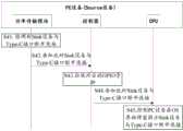
S11:功率传输模块识别到Sink设备接入,打开内部对应的开关。S11: The power transmission module recognizes that the sink device is connected, and turns on the corresponding internal switch.
第二Type-C接口22接入Sink设备时,功率传输模块和Sink设备通过第二Type-C接口22的CC pin握手,确定自身为Source设备,接入的为Sink设备。功率传输模块打开与第二Type-C接口22对应的开关,也即打开SW2,先对Sink设备进行低规格的充电。When the second Type-
在一些实施例中,PC设备此时的对外充电规格为:充电电压5V,充电电流3A。In some embodiments, the external charging specifications of the PC device at this time are: charging
充电电压为功率变换电路的26的输出电压,在一些实施例中,功率变换电路的26具体为降压(Buck)电路,用于将从充电电路23获取的电压降低至5V的电压。The charging voltage is the output voltage of the
S12:功率传输模块告知控制器有Sink设备接入。S12: The power transmission module notifies the controller that a Sink device is connected.
功率传输模块25通过集成电路(inter-integrated circuit,I2C)总线告知控制器24此时有Sink设备接入。The
其中,I2C总线是一种双向同步串行总线,包括一根串行数据线(serial dataline,SDA)和一根串行时钟线(derail clock line,SCL),再次不多做赘述。控制器24也可以通过I2C总线控制充电电路23的工作。Among them, the I2C bus is a bidirectional synchronous serial bus, including a serial data line (serial data line, SDA) and a serial clock line (derail clock line, SCL), and again will not repeat them here. The
S13:控制器告知CPU有 Sink设备接入。S13: The controller informs the CPU that a Sink device is connected.
控制器通过增强型串行外设接口(enhanced serial peripheral interface,eSPI)总线告知CPU有 Sink设备接入。The controller informs the CPU that a Sink device is connected through an enhanced serial peripheral interface (enhanced serial peripheral interface, eSPI) bus.
S14:CPU控制PC设备在操作系统界面进行弹窗提示。S14: The CPU controls the PC device to prompt a pop-up window on the operating system interface.
PC设备的操作系统(Operating System,OS)界面可以通过弹窗的形式,提示用户选择是否需要对接入的Sink设备进行快速充电。The operating system (Operating System, OS) interface of the PC device may prompt the user to select whether to fast charge the connected Sink device in the form of a pop-up window.
参见图5,该图为本申请实施例提供的弹窗界面的示意图一。Refer to FIG. 5 , which is a first schematic diagram of a pop-up window interface provided by an embodiment of the present application.
用户可以通过OS界面的弹窗功能选择是否需要开启对Sink设备的快速充电。可以理解的是,以上的弹窗界面仅是一种可能的实现方式,并不构成对于本申请实现方式的具体限定。弹窗界面的大小、布局还可以采用其它的方式,在此不再赘述。The user can choose whether to enable fast charging of the Sink device through the pop-up function of the OS interface. It can be understood that the above pop-up window interface is only a possible implementation manner, and does not constitute a specific limitation on the implementation manner of the present application. The size and layout of the pop-up window interface can also adopt other methods, which will not be repeated here.
可以理解的是,用户还可以在弹窗界面或者PC设备的与电源控制相关的设置菜单中设置默认的配置选项,例如设置总是询问,则每当PC设备通过Type-C接口连接Sink设备时,PC设备均会进行弹窗询问;又例如可以设置为默认启动对Sink设备进行快速充电,则每当PC设备通过Type-C接口连接Sink设备时,PC设备不再进行弹窗提示,而是自动启动对Sink设备的快速充电流程;在例如可以设置为默认关闭对Sink设备的快速充电功能,则每当PC设备通过Type-C接口连接Sink设备时,PC设备不再进行弹窗提示,且不启动对Sink设备的快速充电流程。It is understandable that the user can also set the default configuration options in the pop-up window interface or the power control-related setting menu of the PC device. , the PC device will pop-up to ask; for example, it can be set to enable fast charging of the sink device by default, then whenever the PC device connects to the sink device through the Type-C interface, the PC device will no longer prompt the pop-up window, but Automatically start the fast charging process for the sink device; for example, it can be set to disable the fast charging function for the sink device by default, then whenever the PC device connects to the sink device through the Type-C interface, the PC device will no longer prompt the pop-up window, and Do not start the fast charging process for the sink device.
S15:用户选择对Sink设备进行快速充电。S15: The user chooses to fast charge the Sink device.
可以理解的是,用户也可以在弹窗界面选择不对Sink设备进行快速充电。例如用户直接在弹窗界面选择不对Sink设备进行快速充电,或者用户关闭弹窗界面未进行操作,均可以视作用户触发了不对Sink设备进行快速充电的选择。此时则不再继续进行后续的流程,PC设备维持对Sink设备的低功率充电。It is understandable that the user can also choose not to fast charge the Sink device on the pop-up window interface. For example, the user directly chooses not to perform fast charging on the Sink device in the pop-up window interface, or the user closes the pop-up window interface without performing any operation, which can be regarded as the user triggering the selection not to perform fast charging on the Sink device. At this time, the subsequent process is not continued, and the PC device maintains the low-power charging of the Sink device.
以下说明中以用户选择对Sink设备进行快速充电为例继续说明。In the following description, the user chooses to fast charge the Sink device as an example to continue the description.
S16:CPU告知控制器用户请求进行对Sink设备的快速充电。S16: The CPU informs the controller that the user requests fast charging of the Sink device.
CPU27通过eSPI总线告知控制器24用户选择对Sink设备进行快速充电。The
S17:控制器告知功率传输模块开始向Sink设备发送充电能力消息。S17: The controller informs the power transmission module to start sending a charging capability message to the Sink device.
控制器24通过I2C总线告知功率传输模块25开始向Sink设备发送充电能力(Source_Capabilites)消息。The
Source_Capabilites消息中携带有第二充电规格对应的充电电流参数和充电电压参数。本申请实施例中对于Source_Capabilites消息中携带的充电电流参数和充电电压参数不作具体限定,例如充电电压参数为20V,充电电流参数为3A;又例如充电电压参数为20V,充电电流参数为5A。The Source_Capabilites message carries the charging current parameter and the charging voltage parameter corresponding to the second charging specification. In the embodiment of the present application, the charging current parameter and the charging voltage parameter carried in the Source_Capabilites message are not specifically limited, for example, the charging voltage parameter is 20V, and the charging current parameter is 3A; and for example, the charging voltage parameter is 20V, and the charging current parameter is 5A.
S18:功率传输模块25向Sink设备发送Source_Capabilites消息。S18: The
PC设备作为Source设备,向Sink设备发送Source_Capabilites消息,以告知Sink设备自身的充电规格。该充电规格也即此时外部充电器对PC设备的充电规格。As the Source device, the PC device sends a Source_Capabilites message to the Sink device to inform the Sink device of its own charging specifications. The charging specification is also the charging specification of the external charger for the PC device at this time.
S19:Sink设备向功率传输模块25回复GoodCRC消息。S19: The Sink device replies a GoodCRC message to the
Sink设备向PC设备回复GoodCRC消息,以表示自身受到了PC设备发送的Source_Capabilites消息。The Sink device replies a GoodCRC message to the PC device to indicate that it has received the Source_Capabilites message sent by the PC device.
S20:Sink设备向功率传输模块25发送Request消息。S20: the Sink device sends a Request message to the
Sink设备接收到Source_Capabilites消息后,解析获取其中指示的充电规格,当判断自身能够满足该充电规格时,向PC设备发送请求(Request)消息。After receiving the Source_Capabilites message, the Sink device parses and acquires the charging specification indicated therein, and sends a Request message to the PC device when it judges that it can meet the charging specification.
Request消息表示Sink设备可支持当前Source_Capabilites消息中携带的充电规格,请求进行快速充电。The Request message indicates that the Sink device can support the charging specification carried in the current Source_Capabilites message, and requests fast charging.
S21:功率传输模块25向Sink设备回复GoodCRC消息。S21: The
PC设备向Sink设备回复GoodCRC消息,表示自身收到Sink设备发送的Request消息。The PC device replies a GoodCRC message to the Sink device, indicating that it has received the Request message sent by the Sink device.
S22:功率传输模块25向Sink设备发送Accept消息。S22: The
PC设备接收到Request消息后,解析其中的信息,判断可以满足Sink设备请求的充电规格,向Sink设备发送接收(Accept)消息。After receiving the Request message, the PC device analyzes the information therein, judges that the charging specification requested by the Sink device can be met, and sends an Accept message to the Sink device.
Accept消息表示PC设备接受了Sink设备的快速充电请求。The Accept message indicates that the PC device has accepted the fast charging request of the Sink device.
S23:Sink设备向功率传输模块25回复GoodCRC消息。S23: The Sink device replies a GoodCRC message to the
Sink设备向PC设备回复GoodCRC消息,表示自身已经接收到PC设备发送的Accept消息。The sink device replies a GoodCRC message to the PC device, indicating that it has received the Accept message sent by the PC device.
以上的过程形成的充电日志可以如下表所示。The charging log formed by the above process can be shown in the following table.
表1:充电日志表Table 1: Charging log table

S24:功率传输模块断开内部对应的开关。S24: The power transmission module turns off the corresponding internal switch.
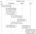
也即功率传输模块25控制SW2断开,停止对Sink设备进行的低功率充电。That is to say, the
S25:功率传输模块告知控制器开始对Sink设备进行快速充电。S25: the power transmission module notifies the controller to start fast charging the Sink device.
功率传输模块25通过I2C总线告知控制器Sink设备已经准备好,开始对Sink设备进行快速充电。The
S26:控制器拉高对应的GPIO管脚。S26: the controller pulls up the corresponding GPIO pin.
也即此时控制器24拉高第二Type-C接口22对应的EC_GPIO2管脚,第四二极管D4导通, S3和S4的栅极连接高电平,S3和S4被导通。That is, at this time, the
此时,外部充电器经过第一Type-C接口21-S1-S2的通路对PC设备充电的同时,还经过第一Type-C接口21-S1-S2-S4-S3-第二Type-C接口22的通路对外部接入的Sink设备提供大功率电源。At this time, while the external charger is charging the PC device through the first Type-C interface 21-S1-S2, it also passes through the first Type-C interface 21-S1-S2-S4-S3-second Type-C The path of the
进一步的,为了使用户知晓对Sink设备的快充已经开启,还可以包括以下的步骤。Further, in order to let the user know that the fast charging of the Sink device has been started, the following steps may also be included.
S27:控制器告知CPU已经开启了对Sink设备的快速充电。S27: the controller informs the CPU that fast charging of the Sink device has been started.
控制器24通过eSPI总线告知CPU此时已经开启了对Sink设备的快速充电。The
S28:CPU控制PC设备在OS界面弹窗提示对Sink设备的快速充电已经开启。S28: The CPU controls the PC device to prompt on the OS interface that the fast charging of the Sink device has been enabled.
参见图6,该图为本申请实施例提供的弹窗界面的示意图二。Refer to FIG. 6 , which is a second schematic diagram of the pop-up window interface provided by the embodiment of the present application.
可以通过OS界面的弹窗功能向用户展示当前已经开启对Sink设备的快速充电。The pop-up function of the OS interface can be used to show the user that the fast charging of the Sink device is currently enabled.
可以理解的是,以上的弹窗界面仅是一种可能的实现方式,并不构成对于本申请实现方式的具体限定。弹窗界面的大小、布局还可以采用其它的方式,在此不再赘述。It can be understood that the above pop-up window interface is only a possible implementation manner, and does not constitute a specific limitation on the implementation manner of the present application. The size and layout of the pop-up window interface can also adopt other methods, which will not be repeated here.
进一步的,弹窗界面上还可以包括“是否停止对该设备进行快速充电”的选项,以供用户根据需求结束对于Sink设备的快速充电。Further, the pop-up window interface may also include an option of "whether to stop the fast charging of the device", so that the user can end the fast charging of the Sink device according to the requirement.
低功率充电时的充电规格为第一充电规格,外部充电器的充电规格为第二充电规格,该第二充电规格大于第一充电规格,因此当S3和S4断开后,实现了对于Sink设备的快速充电。The charging specification for low-power charging is the first charging specification, and the charging specification for the external charger is the second charging specification, which is greater than the first charging specification. Therefore, when S3 and S4 are disconnected, the Sink device is realized fast charging.
实际应用中,可能存在Sink设备不支持快速充电,或者不支持PC设备提供的充电规格。此时PC设备实施的流程参见下图进行说明。In practical applications, there may be that the sink device does not support fast charging, or does not support the charging specification provided by the PC device. At this time, the process implemented by the PC device is described in the figure below.
一并参见图3和图7。其中,图7为本申请实施例提供的快速充电失败时的流程图。See Figure 3 and Figure 7 together. Wherein, FIG. 7 is a flow chart when the fast charging fails provided by the embodiment of the present application.
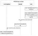
S201:功率传输模块确认Sink设备不支持Source_Capabilites消息中携带的充电规格。S201: The power transmission module confirms that the Sink device does not support the charging specification carried in the Source_Capabilites message.
当第二Type-C接口22接入的Sink设备不支持Source_Capabilites消息中携带的充电规格时,在一种可能的实现方式中,此时功率传输模块无法接受到Sink设备发送的Request消息,此时功率传输模块可以向Sink设备再次发送相同的Source_Capabilites消息,继续等待Sink设备回应,如果经过一共第一预设次数的发送后,还是未接收到Sink设备回复的GoodCRC消息,或者未接收到Sink设备回复的Request消息,则确定Sink设备不支持Source_Capabilites消息中携带的充电规格;在另一种可能的实现方式中,功率传输模块能够接收到Sink设备发送的指示不接受充电规格的信息,则功率传输模块确定Sink设备不支持Source_Capabilites消息中携带的充电规格。When the Sink device connected to the second Type-
本申请实施例对第一预设次数不作具体限定,在一些实施例中,第一预设次数可以设置为3次。The embodiment of the present application does not specifically limit the first preset number of times, and in some embodiments, the first preset number of times may be set to 3 times.
S202:功率传输模块告知控制器快速充电请求失败。S202: The power transmission module notifies the controller that the fast charging request fails.
功率传输模块25通过I2C总线告知控制器24快速充电请求失败。The
S203:控制器告知CPU快速充电请求失败。S203: the controller informs the CPU that the fast charging request fails.
控制器24通过eSPI总线告知CPU27快速充电请求失败。The
S204:CPU控制PC设备在OS界面弹窗提示对Sink设备的快速充电请求失败。S204: The CPU controls the PC device to prompt a pop-up window on the OS interface that the fast charging request to the Sink device fails.
参见图8,该图为本申请实施例提供的弹窗界面的示意图三。Refer to FIG. 8 , which is a third schematic diagram of the pop-up window interface provided by the embodiment of the present application.
可以理解的是,以上的弹窗界面仅是一种可能的实现方式,并不构成对于本申请实现方式的具体限定。弹窗界面的大小、布局还可以采用其它的方式,在此不再赘述。It can be understood that the above pop-up window interface is only a possible implementation manner, and does not constitute a specific limitation on the implementation manner of the present application. The size and layout of the pop-up window interface can also adopt other methods, which will not be repeated here.
进一步的,弹窗界面上还可以包括“查看请求失败原因”的选项,以供用户确定快速充电失败的原因。Further, the pop-up window interface may also include an option of "checking the reason for the request failure", so that the user can determine the reason for the fast charging failure.
以上实施例中说明了PC设备启动对Sink设备进行快速充电的过程,下面说明PC设备停止对Sink设备进行快速充电的过程。In the above embodiments, the process of the PC device starting to fast charge the Sink device is described, and the following describes the process of the PC device stopping the fast charging of the Sink device.
下面说明首先Sink设备未断开连接,用户主动控制PC设备停止对Sink设备进行快速充电的实现方式。The following describes how the sink device is not disconnected first, and the user actively controls the PC device to stop fast charging the sink device.
在一种可能的实现方式中,由用户在OS界面选择停止对Sink设备进行快速充电。In a possible implementation manner, the user chooses to stop the fast charging of the Sink device on the OS interface.
参见图9,该图为本申请实施例提供的停止对Sink设备进行快速充电的示意图一。Refer to FIG. 9 , which is a first schematic diagram of stopping fast charging of the Sink device provided by the embodiment of the present application.
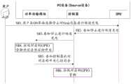
S31:用户在OS界面选择停止对Sink设备进行快速充电。S31: The user chooses to stop fast charging the Sink device on the OS interface.
参见图10,该图为本申请实施例提供的OS界面的示意图一。Refer to FIG. 10 , which is a first schematic diagram of an OS interface provided by an embodiment of the present application.
可以理解的是,以上的OS界面仅是一种可能的实现方式,并不构成对于本申请实现方式的具体限定。OS界面的大小、布局还可以采用其它的方式,在此不再赘述。It can be understood that the above OS interface is only a possible implementation manner, and does not constitute a specific limitation on the implementation manner of the present application. The size and layout of the OS interface can also adopt other methods, which will not be repeated here.
用户通过主动选择停止对Sink设备进行快速充电,以关闭该功能。The user actively chooses to stop the fast charging of the sink device to turn off this function.
S32:CPU告知控制器停止对Sink设备进行快速充电。S32: The CPU informs the controller to stop fast charging the Sink device.
CPU通过eSPI总线告知控制器停止对Sink设备进行快速充电。The CPU informs the controller to stop fast charging the Sink device through the eSPI bus.
S33:控制器拉低对应的GPIO管脚。S33: the controller pulls down the corresponding GPIO pin.
也即控制器24拉低第二Type-C接口22对应的EC_GPIO2管脚。That is, the
S34:控制器告知功率传输模块停止对Sink设备进行快速充电。S34: The controller informs the power transmission module to stop fast charging the Sink device.
控制器24通过I2C总线告知功率传输模块25停止对Sink设备进行快速充电,切换至对Sink设备进行低功率充电。The
S35:功率传输模块拉低对应的GPIO管脚并闭合对应的开关。S35: the power transmission module pulls down the corresponding GPIO pin and closes the corresponding switch.
此时控制器24拉低第二Type-C接口22对应的EC_GPIO2管脚,功率传输模块25的PD_GPIO2管脚也维持低电平,使得 S3和S4的栅极连接低电平,S3和S4断开。At this time, the
外部充电器经过第一Type-C接口21-S1-S2的通路对PC设备充电,但是对外部接入的Sink设备供电的电路被断开。The external charger charges the PC device through the path of the first Type-C interface 21-S1-S2, but the circuit for supplying power to the externally connected Sink device is disconnected.
可以理解的是,当对Sink设备进行快速充电时,EC_GPIO2管脚拉高,PD_GPIO2管脚可以拉高也可以拉低,当PD_GPIO2管脚拉高时,停止PD_GPIO2管脚时PD_GPIO2管脚需要切换为拉低状态;当PD_GPIO2管脚拉低时,停止PD_GPIO2管脚时PD_GPIO2管脚维持拉低状态。It is understandable that when the Sink device is fast charged, the EC_GPIO2 pin is pulled high, and the PD_GPIO2 pin can be pulled high or low. When the PD_GPIO2 pin is pulled high, the PD_GPIO2 pin needs to be switched to Low state; when the PD_GPIO2 pin is low, the PD_GPIO2 pin remains low when the PD_GPIO2 pin is stopped.
功率传输模块25控制对应的SW2开关打开后,功率变换电路26输出,为Sink设备供电。After the
本申请实施例中先控制S3和S4断开,再闭合SW2的原因是避免出现大电流和大电压通过SW2倒灌如功率传输设备。In the embodiment of the present application, the reason why S3 and S4 are first controlled to be disconnected, and then SW2 is closed is to avoid large current and large voltage flowing backward through SW2 such as power transmission equipment.
下面说明当Sink设备与PC设备的Type-C接口断开连接时,PC设备停止快速充电的流程。The following describes the process of stopping fast charging of the PC device when the Sink device is disconnected from the Type-C interface of the PC device.
参见图11,该图为本申请实施例提供的停止对Sink设备进行快速充电的示意图二。Refer to FIG. 11 , which is a second schematic diagram of stopping fast charging of the Sink device provided by the embodiment of the present application.
该方法包括以下步骤:The method includes the following steps:
S41:功率传输模块检测到Sink设备与Type-C接口断开连接。S41: The power transmission module detects that the Sink device is disconnected from the Type-C interface.
此时由于Sink设备与Type-C接口断开连接,无需外供电,功率传输模块25会控制内部的开关SW1和SW2均断开,以及将PD_GPIO2拉低。功率传输模块25维持PD_GPIO1拉高,以维持外部充电器对PC设备的供电。At this time, since the Sink device is disconnected from the Type-C interface, no external power supply is required, the
在一种可能的实现方式中,功率传输模块25利用第二Type-C接口22的CC pin的握手信号确定出Sink设备断开连接。In a possible implementation manner, the
S42:功率传输模块告知控制器此时Sink设备与Type-C接口断开连接。S42: The power transmission module notifies the controller that the Sink device is disconnected from the Type-C interface at this time.
功率传输模块25通过I2C总线告知控制器24当前Sink设备与Type-C接口断开连接。The
S43:控制器拉低对应的GPIO管脚。S43: the controller pulls down the corresponding GPIO pin.
控制器24拉低第二Type-C接口22对应的EC_GPIO2管脚,功率传输模块25的PD_GPIO2管脚也维持低电平,使得 S3和S4的栅极连接低电平,S3和S4断开。The
S44:控制器告知CPU 当前Sink设备与Type-C接口断开连接。S44: the controller informs the CPU that the current Sink device is disconnected from the Type-C interface.
控制器通过eSPI总线告知CPU当前Sink设备与第二Type-C接口22断开连接。The controller informs the CPU that the current Sink device is disconnected from the second Type-
S45:CPU控制PC设备在OS界面弹窗提示Sink设备与Type-C接口断开连接。S45: The CPU controls the PC device to prompt a pop-up window on the OS interface to disconnect the Sink device from the Type-C interface.
参见图12,该图为本申请实施例提供的弹窗界面的示意图四。Refer to FIG. 12 , which is a schematic diagram 4 of the pop-up window interface provided by the embodiment of the present application.
可以理解的是,以上的弹窗界面仅是一种可能的实现方式,并不构成对于本申请实现方式的具体限定。弹窗界面的大小、布局还可以采用其它的方式,在此不再赘述。It can be understood that the above pop-up window interface is only a possible implementation manner, and does not constitute a specific limitation on the implementation manner of the present application. The size and layout of the pop-up window interface can also adopt other methods, which will not be repeated here.
下面说明当PC设备的外部充电器与PC设备的Type-C接口断开连接时,PC设备停止对Sink设备进行快速充电的流程。The following describes the procedure for the PC device to stop fast charging the Sink device when the external charger of the PC device is disconnected from the Type-C interface of the PC device.
参见图13,该图为本申请实施例提供的停止对Sink设备进行快速充电的示意图三。Refer to FIG. 13 , which is a third schematic diagram of stopping fast charging of the Sink device provided by the embodiment of the present application.
该方法包括以下步骤:The method includes the following steps:
S41:用户断开外部充电器与PC设备的Type-C接口的连接。S41: The user disconnects the connection between the external charger and the Type-C interface of the PC device.
用户将PC设备的第一Type-C接口21与外部充电器的连接断开。The user disconnects the first Type-
S42:功率传输模块检测到外部充电器与第一Type-C接口断开连接。S42: The power transmission module detects that the external charger is disconnected from the first Type-C interface.
在一种可能的实现方式中,功率传输模块25利用与第一Type-C接口21的CC pin的握手信号确定出外部充电器断开连接。In a possible implementation manner, the
此时停止对Sink进行快速充电,开始对Sink设备进行低功率充电。At this time, the fast charging of the sink is stopped, and the low-power charging of the sink device is started.
S43:功率传输模块拉低第一Type-C接口和第二Type-C接口各自对应的GPIO口。S43: The power transmission module pulls down the GPIO ports respectively corresponding to the first Type-C interface and the second Type-C interface.
S44:功率传输模块告知控制器外部充电器与第一Type-C接口的连接断开。S44: The power transmission module notifies the controller that the connection between the external charger and the first Type-C interface is disconnected.
功率传输模块25通过I2C总线告知控制器24外部充电器与PC设备的第一Type-C接21口的连接断开,停止进行快速充电。The
S45:控制器拉低第二Type-C接口对应的GPIO口。S45: the controller pulls down the GPIO port corresponding to the second Type-C interface.
此时,S3和S4的栅极连接低电平,S3和S4断开。At this time, the gates of S3 and S4 are connected to low level, and S3 and S4 are disconnected.
S46:控制器告知功率传输模块此时第二Type-C接口对应的GPIO口已经拉低。S46: The controller informs the power transmission module that the GPIO port corresponding to the second Type-C interface has been pulled down at this time.
控制器24可以通过I2C总线告知功率传输模块25第二Type-C接口对应的GPIO口已经拉低,可以开启对Sink设备的低功率充电。The
S47:功率传输模块控制第二Type-C接口对应的开关闭合。S47: The power transmission module controls the switch corresponding to the second Type-C interface to close.
功率传输模块还可以在控制对应的开关闭合后,告知控制器对应的开关已经闭合。The power transmission module may also notify the controller that the corresponding switch is closed after controlling the corresponding switch to be closed.
也即功率传输模块控制SW2闭合,此时功率变换电路26工作,用于为Sink设备提供电源,进行低功率的充电。That is to say, the power transmission module controls SW2 to close, and at this time the
本申请实施例中先控制S3和S4断开,再闭合SW2的原因是避免出现大电流和大电压通过SW2倒灌如功率传输设备。In the embodiment of the present application, the reason why S3 and S4 are first controlled to be disconnected, and then SW2 is closed is to avoid large current and large voltage flowing backward through SW2 such as power transmission equipment.
S48:控制器告知CPU此时外部充电器与第一Type-C接口的连接断开。S48: The controller informs the CPU that the connection between the external charger and the first Type-C interface is disconnected at this time.
控制器通过eSPI总线告知CPU此时外部充电器与第一Type-C接口的连接断开,快速充电已经中断。The controller informs the CPU through the eSPI bus that the connection between the external charger and the first Type-C interface is disconnected at this time, and the fast charging has been interrupted.
S49:CPU控制PC设备在OS界面弹窗提示外部充电器已经断开连接,对Sink设备的快速充电已经停止。S49: The CPU controls the PC device to prompt a pop-up window on the OS interface that the external charger has been disconnected, and the fast charging of the Sink device has stopped.
参见图14,该图为本申请实施例提供的弹窗界面的示意图五。Refer to FIG. 14 , which is a schematic diagram five of the pop-up window interface provided by the embodiment of the present application.
可以理解的是,以上的弹窗界面仅是一种可能的实现方式,并不构成对于本申请实现方式的具体限定。弹窗界面的大小、布局还可以采用其它的方式,在此不再赘述。It can be understood that the above pop-up window interface is only a possible implementation manner, and does not constitute a specific limitation on the implementation manner of the present application. The size and layout of the pop-up window interface can also adopt other methods, which will not be repeated here.
下面说明当PC设备为了启动性能模式,主动停止对Sink设备进行快速充电的流程。The following describes the process for the PC device to actively stop fast charging the Sink device in order to start the performance mode.
参见图15,该图为本申请实施例提供的停止对Sink设备进行快速充电的示意图四。Refer to FIG. 15 , which is a schematic diagram 4 of stopping fast charging of the Sink device provided by the embodiment of the present application.
该方法包括以下步骤:The method includes the following steps:
S51:CPU检测到PC设备开启性能模式。S51: The CPU detects that the performance mode of the PC device is enabled.
其中,PC设备的性能模式主要针对底层硬件、能源策略、工作负载进行了优化,不再对性能和效率进行折衷平衡,而试图发挥出PC设备的最大性能,一般用于PC设备进行游戏的场景,或者运行大型软件的场景。Among them, the performance mode of PC equipment is mainly optimized for the underlying hardware, energy strategy, and workload. It no longer compromises performance and efficiency, but tries to maximize the performance of PC equipment. It is generally used in scenarios where PC equipment plays games. , or the scenario of running large software.
S52:CPU控制PC设备在OS界面弹窗提示性能模式已开启,停止对Sink设备的快速充电。S52: The CPU controls the PC device to prompt that the performance mode has been activated on the OS interface, and stop fast charging of the Sink device.
参见图16,该图为本申请实施例提供的弹窗界面的示意图六。Refer to FIG. 16 , which is a sixth schematic diagram of the pop-up window interface provided by the embodiment of the present application.
可以理解的是,以上的弹窗界面仅是一种可能的实现方式,并不构成对于本申请实现方式的具体限定。弹窗界面的大小、布局还可以采用其它的方式,在此不再赘述。It can be understood that the above pop-up window interface is only a possible implementation manner, and does not constitute a specific limitation on the implementation manner of the present application. The size and layout of the pop-up window interface can also adopt other methods, which will not be repeated here.
通过弹窗界面,告知用户当前PC设备的性能模式已开启,对Sink设备的充电方式已经由快速充电切换为低功率充电。在另一些实施例中,弹窗界面还可以包括“是否关闭性能模式并重启快速充电”选项,当用户选择是时,则PC设备关闭性能模式,并按照图4中S16-S28的步骤重新开启对Sink设备的快速充电。Through the pop-up window interface, the user is informed that the performance mode of the current PC device has been turned on, and the charging method for the Sink device has been switched from fast charging to low-power charging. In some other embodiments, the pop-up window interface may also include the option "whether to close the performance mode and restart fast charging", when the user selects yes, the PC device closes the performance mode, and restarts according to the steps of S16-S28 in Figure 4 Fast charging of sink devices.
S53:CPU告知控制器停止对Sink设备进行快速充电。S53: The CPU informs the controller to stop fast charging the Sink device.
CPU27通过eSPI总线告知控制器24停止对Sink设备进行快速充电。The
S54:控制器拉低对应的GPIO管脚。S54: the controller pulls down the corresponding GPIO pin.
也即控制器24拉低第二Type-C接口22对应的EC_GPIO2管脚。That is, the
S55:控制器告知功率传输模块停止对Sink设备进行快速充电。S55: the controller informs the power transmission module to stop fast charging the Sink device.
控制器24通过I2C总线告知功率传输模块25停止对Sink设备进行快速充电,切换至对Sink设备进行低功率充电。The
S56:功率传输模块拉低对应的GPIO管脚并打开对应的开关。S56: the power transmission module pulls down the corresponding GPIO pin and turns on the corresponding switch.
此时控制器24拉低第二Type-C接口22对应的EC_GPIO2管脚,功率传输模块25的PD_GPIO2管脚也维持低电平,使得 S3和S4的栅极连接低电平,S3和S4断开。At this time, the
功率传输模块25控制对应的SW2开关打开后,功率变换电路26输出,为Sink设备供电。After the
可以理解的是,以上步骤顺序仅是为了方便说明,并不构成对于本申请技术方案的限定。例如,实际应用中,S52的顺序可以在低功率充电开启后执行,当功率传输模块导通SW2后,通过I2C接口告知控制器快速充电已经关闭,控制器通过eSPI接口告知CPU快速充电已经关闭,再由CPU控制PC设备在OS界面弹窗提示性能模式已开启,对Sink设备的快速充电已经关闭。It can be understood that the sequence of the above steps is only for convenience of description, and does not constitute a limitation to the technical solution of the present application. For example, in practical applications, the sequence of S52 can be executed after the low-power charging is turned on. When the power transmission module turns on SW2, it will notify the controller through the I2C interface that the fast charging has been turned off, and the controller will notify the CPU through the eSPI interface that the fast charging has been turned off. Then the CPU controls the PC device to pop up a window on the OS interface to prompt that the performance mode has been turned on, and the fast charging of the sink device has been turned off.
在另一些实施例中,PC设备在对Sink设备进行快速充电的过程中,还可以与Sink设备进行交互以获取Sink设备当前的电量,当电子设备充满电时,或者当电子设备的电量大于预设电量值时,停止对电子设备进行快速充电,并且换为低功率充电,还可以通过OS界面弹窗提示Sink设备已充满电,快速充电模式已经切换为低功率充电模式。In some other embodiments, the PC device can also interact with the Sink device to obtain the current power of the Sink device during the process of fast charging the Sink device. When the electronic device is fully charged, or when the power of the electronic device is greater than the preset When setting the power value, stop fast charging of electronic devices and switch to low-power charging. You can also use the pop-up window on the OS interface to prompt that the Sink device is fully charged, and the fast charging mode has been switched to low-power charging mode.
可以理解的是,对于PC设备开启性能模式、用户主动选择关闭快速充电以及Sink设备充满电的情况,均可以视作此时需要停止按照第二充电规格对Sink设备进行充电。It can be understood that, when the performance mode of the PC device is turned on, the user actively chooses to turn off fast charging, and the sink device is fully charged, it can be regarded as that it is necessary to stop charging the sink device according to the second charging specification at this time.
综上所述,利用本申请实施例提供的技术方案,在电子设备上未增加复杂的IC,仅增加了结构简单,硬件成本低的二极管,即可以使得电子设备在利用一个Type-C接口进行快速充电的同时,利用其它的Type-C接口对外部接入的Sink设备进行快速充电,也即实现了利用一个外部充电器同时对多个电子设备进行快速充电的功能,满足了用户的快速充电需求,提升了用户体验。并且该方案的硬件成本低,易于实现,具有较高的实用性。In summary, using the technical solution provided by the embodiment of the present application, no complex IC is added to the electronic device, only a diode with a simple structure and low hardware cost is added, that is, the electronic device can be connected using a Type-C interface. At the same time of fast charging, use other Type-C interfaces to quickly charge externally connected sink devices, that is, to realize the function of using an external charger to quickly charge multiple electronic devices at the same time, which meets the needs of users for fast charging. demand and improve the user experience. Moreover, the scheme has low hardware cost, is easy to implement, and has high practicability.
下面说明另一种快速充电方案的实现方式。The implementation of another fast charging scheme is described below.
参见图17,该图为本申请实施例提供的另一种电子设备的示意图。Referring to FIG. 17 , this figure is a schematic diagram of another electronic device provided by an embodiment of the present application.
该电子设备与图3所示的电子设备的区别在于,本申请实施例中的二极管电路28还包括第五二极管D5和第六二极管D6。The difference between this electronic device and the electronic device shown in FIG. 3 is that the
其中,第五二极管D5的阳极连接功率传输模块的开关SW1,第五二极管D5的阴极连接在第一Type-C接口21以及S1之间,也即阴极连接在第一Type-C接口21的VBUS上;第六二极管D6的阳极连接功率传输模块的开关SW2,第六二极管D6的阴极连接在第二Type-C接口22以及S3之间,也即阴极连接在第二Type-C接口22的VBUS上。Wherein, the anode of the fifth diode D5 is connected to the switch SW1 of the power transmission module, and the cathode of the fifth diode D5 is connected between the first Type-
设置D5和D6的作用时,当开启对Sink设备的快速充电时,控制器可以先控制GPIO口拉高,以使S3和S4接通,此时电流和电压不会反灌至功率传输模块;然后功率传输模块控制内部的开关断开,进而避免Sink设备在由低功率充电向快速充电的过程中出现短暂掉电的情况。When setting the functions of D5 and D6, when the fast charging of the sink device is turned on, the controller can first control the GPIO port to be pulled high so that S3 and S4 are connected. At this time, the current and voltage will not be fed back to the power transmission module; Then the power transmission module controls the internal switch to be turned off, thereby avoiding the short-term power loss of the Sink device during the process from low-power charging to fast charging.
下面具体说明第二Type-C接口22接入Sink设备时,PC设备对Sink实现快速充电的流程。The following describes in detail the procedure for the PC device to quickly charge the Sink when the second Type-
参见图18,该图为本申请实施例提供的PC设备对Sink设备进行快速充电的流程图二。Referring to FIG. 18 , this figure is the second flowchart of fast charging of the Sink device by the PC device provided by the embodiment of the present application.
包括以下步骤:Include the following steps:
S61:功率传输模块识别到Sink设备接入,打开对应的开关。S61: The power transmission module recognizes that the sink device is connected, and turns on a corresponding switch.
第二Type-C接口22接入Sink设备时,功率传输模块25和Sink设备通过第二Type-C接口22的CC pin握手,确定自身为Source设备,接入的为Sink设备。When the second Type-
功率传输模块25打开与第二Type-C接口22对应的开关,也即打开SW2,先对Sink设备进行低规格的充电。The
在一些实施例中,PC设备此时的对外充电规格为:充电电压5V,充电电流3A。In some embodiments, the external charging specifications of the PC device at this time are: charging
S62:功率传输模块告知控制器有Sink设备接入。S62: The power transmission module notifies the controller that a Sink device is connected.
功率传输模块25通过I2C总线告知控制器24此时有Sink设备接入。The
S63:控制器告知CPU有 Sink设备接入。S63: The controller informs the CPU that a Sink device is connected.
控制器24通过 eSPI总线告知CPU有 Sink设备接入。The
S64:CPU控制PC设备在操作系统界面进行弹窗提示。S64: The CPU controls the PC device to prompt a pop-up window on the operating system interface.
PC设备的OS界面可以通过弹窗的形式,提示用户选择是否需要对接入的Sink设备进行快速充电。The OS interface of the PC device can prompt the user to choose whether to fast charge the connected Sink device through a pop-up window.
弹窗界面可以参见以上图5所示。The pop-up interface can be seen in Figure 5 above.
可以理解的是,用户还可以在弹窗界面或者PC设备的与电源控制相关的设置菜单中设置默认的配置选项,例如设置总是询问,则每当PC设备通过Type-C接口连接Sink设备时,PC设备均会进行弹窗询问;又例如可以设置为默认启动对Sink设备进行快速充电,则每当PC设备通过Type-C接口连接Sink设备时,PC设备不再进行弹窗提示,而是自动启动对Sink设备的快速充电流程;在例如可以设置为默认关闭对Sink设备的快速充电功能,则每当PC设备通过Type-C接口连接Sink设备时,PC设备不再进行弹窗提示,且不启动对Sink设备的快速充电流程。It is understandable that the user can also set the default configuration options in the pop-up window interface or the power control-related setting menu of the PC device. , the PC device will pop-up to ask; for example, it can be set to enable fast charging of the sink device by default, then whenever the PC device connects to the sink device through the Type-C interface, the PC device will no longer prompt the pop-up window, but Automatically start the fast charging process for the sink device; for example, it can be set to disable the fast charging function for the sink device by default, then whenever the PC device connects to the sink device through the Type-C interface, the PC device will no longer prompt the pop-up window, and Do not start the fast charging process for the sink device.
S65:用户选择对Sink设备进行快速充电。S65: The user chooses to fast charge the Sink device.
可以理解的是,用户也可以在弹窗界面选择不对Sink设备进行快速充电。例如用户直接在弹窗界面选择不对Sink设备进行快速充电,或者用户关闭弹窗界面未进行操作,均可以视作用户触发了不对Sink设备进行快速充电的选择。此时则不再继续进行后续的流程,PC设备维持对Sink设备的低功率充电。It is understandable that the user can also choose not to fast charge the Sink device on the pop-up window interface. For example, the user directly chooses not to perform fast charging on the Sink device in the pop-up window interface, or the user closes the pop-up window interface without performing any operation, which can be regarded as the user triggering the selection not to perform fast charging on the Sink device. At this time, the subsequent process is not continued, and the PC device maintains the low-power charging of the Sink device.
以下说明中以用户选择对Sink设备进行快速充电为例继续说明。In the following description, the user chooses to fast charge the Sink device as an example to continue the description.
S66:CPU告知控制器用户请求进行对Sink设备的快速充电。S66: The CPU informs the controller that the user requests fast charging of the Sink device.
CPU27通过eSPI总线告知控制器24用户选择对Sink设备进行快速充电。The
S67:控制器告知功率传输模块开始向Sink设备发送充电能力消息。S67: The controller informs the power transmission module to start sending a charging capability message to the Sink device.
控制器24通过I2C总线告知功率传输模块25开始向Sink设备发送充电能力(Source_Capabilites)消息。The
Source_Capabilites消息中携带有PC设备支持的充电电流参数和充电电压参数。本申请实施例中对于Source_Capabilites消息中携带的充电电流参数和充电电压参数不作具体限定,例如充电电压参数为20V,充电电流参数为3A;又例如充电电压参数为20V,充电电流参数为5A。The Source_Capabilites message carries the charging current parameters and charging voltage parameters supported by the PC device. In the embodiment of the present application, the charging current parameter and the charging voltage parameter carried in the Source_Capabilites message are not specifically limited, for example, the charging voltage parameter is 20V, and the charging current parameter is 3A; and for example, the charging voltage parameter is 20V, and the charging current parameter is 5A.
S68:功率传输模块25向Sink设备发送Source_Capabilites消息。S68: The
PC设备作为Source设备,向Sink设备发送Source_Capabilites消息,以告知Sink设备自身的充电规格。As the Source device, the PC device sends a Source_Capabilites message to the Sink device to inform the Sink device of its own charging specifications.
S69:Sink设备向功率传输模块25回复GoodCRC消息。S69: The Sink device replies a GoodCRC message to the
Sink设备向PC设备回复GoodCRC消息,以表示自身受到了PC设备发送的Source_Capabilites消息。The Sink device replies a GoodCRC message to the PC device to indicate that it has received the Source_Capabilites message sent by the PC device.
S70:Sink设备向功率传输模块25发送Request消息。S70: the Sink device sends a Request message to the
Sink设备接收到Source_Capabilites消息后,解析获取其中指示的充电规格,当判断自身能够满足该充电规格时,向PC设备发送请求(Request)消息。After receiving the Source_Capabilites message, the Sink device parses and acquires the charging specification indicated therein, and sends a Request message to the PC device when it judges that it can meet the charging specification.
Request消息表示Sink设备可支持当前Source_Capabilites消息中携带的充电规格,请求按照第二充电规格进行快速充电。The Request message indicates that the Sink device can support the charging specification carried in the current Source_Capabilites message, and requests fast charging according to the second charging specification.
S71:功率传输模块25向Sink设备回复GoodCRC消息。S71: The
PC设备向Sink设备回复GoodCRC消息,表示自身收到Sink设备发送的Request消息。The PC device replies a GoodCRC message to the Sink device, indicating that it has received the Request message sent by the Sink device.
S72:功率传输模块25向Sink设备发送Accept消息。S72: The
PC设备接收到Request消息后,解析其中的信息,判断可以满足Sink设备请求的充电规格,向Sink设备发送接收(Accept)消息。After receiving the Request message, the PC device analyzes the information therein, judges that the charging specification requested by the Sink device can be met, and sends an Accept message to the Sink device.
Accept消息表示PC设备接受了Sink设备的快速充电请求。The Accept message indicates that the PC device has accepted the fast charging request of the Sink device.
S73:Sink设备向功率传输模块25回复GoodCRC消息。S73: The Sink device replies a GoodCRC message to the
Sink设备向PC设备回复GoodCRC消息,表示自身已经接收到PC设备发送的Accept消息。The sink device replies a GoodCRC message to the PC device, indicating that it has received the Accept message sent by the PC device.
S74:功率传输模块25告知控制器开始对Sink设备进行快速充电。S74: The
功率传输模块25通过I2C总线告知控制器Sink设备已经准备好,开始对Sink设备进行快速充电。The
S75:控制器拉高对应的GPIO管脚。S75: The controller pulls up the corresponding GPIO pin.
也即此时控制器24拉高第二Type-C接口22对应的EC_GPIO2管脚,第四二极管D4导通, S3和S4的栅极连接高电平,S3和S4被导通。That is, at this time, the
此时,外部充电器经过第一Type-C接口21-S1-S2的通路对PC设备充电的同时,还经过第一Type-C接口21-S1-S2-S4-S3-第二Type-C接口22的通路对外部接入的Sink设备提供大功率电源。At this time, while the external charger is charging the PC device through the first Type-C interface 21-S1-S2, it also passes through the first Type-C interface 21-S1-S2-S4-S3-second Type-C The path of the
此时SW2还为断开,但是通过S4和S3的大电流被D6阻断,无法反灌至功率传输模块,也即二极管D6实现对功率传输模块的保护,并且还使得PC设备对Sink设备由低功率充电向快速充电切换的过程中,不会短暂断开充电回路。也即在Sink设备端,由低功率充电向快速充电切换的过程中不会出现短暂的充电终端,提升了用户的使用体验。At this time, SW2 is still disconnected, but the large current passing through S4 and S3 is blocked by D6, and cannot be fed back to the power transmission module, that is, diode D6 realizes the protection of the power transmission module, and also makes the PC device to the Sink device by In the process of switching from low-power charging to fast charging, the charging circuit will not be disconnected briefly. That is to say, on the sink device side, there will be no short-term charging terminal during the switch from low-power charging to fast charging, which improves the user experience.
S76:控制器告知功率传输模块对应的GPIO管脚已经拉高。S76: the controller informs the power transmission module that the corresponding GPIO pin has been pulled high.
控制器24通过I2C总线告知功率传输模块EC_GPIO2管脚已经拉高。The
S77:功率传输模块断开内部对应的开关。S77: The power transmission module turns off the corresponding internal switch.
也即功率传输模块25控制SW2断开。That is, the
进一步的,为了使用户知晓对Sink设备的快充已经开启,还可以包括以下的步骤。Further, in order to let the user know that the fast charging of the Sink device has been started, the following steps may also be included.
S78:功率传输模块告知CPU内部对应的开关已经断开。S78: the power transmission module informs the CPU that the corresponding internal switch has been turned off.
S79:控制器告知CPU已经开启了对Sink设备的快速充电。S79: the controller informs the CPU that the fast charging of the sink device has been started.
控制器24通过eSPI总线告知CPU此时已经开启了对Sink设备的快速充电。The
S80:CPU控制PC设备在OS界面弹窗提示对Sink设备的快速充电已经开启。S80: The CPU controls the PC device, and a pop-up window on the OS interface prompts that the fast charging of the Sink device has been turned on.
OS界面的弹窗界面示意图可以参见图6,在此不再赘述。The schematic diagram of the pop-up window interface of the OS interface can be referred to FIG. 6 , which will not be repeated here.
当Sink设备不支持快速充电,或者不支持PC设备提供的充电规格时的实现方式可以参见图7和图8对应的说明,本申请实施例在此不再赘述。When the Sink device does not support fast charging, or does not support the charging specification provided by the PC device, reference may be made to the descriptions corresponding to FIG. 7 and FIG. 8 , and the embodiments of the present application will not be repeated here.
下面说明PC设备停止对Sink设备进行快速充电的过程。The following describes the process of the PC device stopping the fast charging of the Sink device.
下面说明首先Sink设备未断开连接,用户主动控制PC设备停止对Sink设备进行快速充电的实现方式。The following describes how the sink device is not disconnected first, and the user actively controls the PC device to stop fast charging the sink device.
参见图19,该图为本申请实施例提供的停止对Sink设备进行快速充电的示意图五。Refer to FIG. 19 , which is a fifth schematic diagram of stopping fast charging of the Sink device provided by the embodiment of the present application.
S81:用户在OS界面选择停止对Sink设备进行快速充电。S81: The user chooses to stop fast charging the Sink device on the OS interface.
此时的OS界面可以参见图10所示,在此不再赘述。The OS interface at this time can be referred to as shown in FIG. 10 , and will not be repeated here.
S82:CPU告知控制器停止对Sink设备进行快速充电。S82: The CPU informs the controller to stop fast charging the Sink device.
CPU通过eSPI总线告知控制器停止对Sink设备进行快速充电。The CPU informs the controller to stop fast charging the Sink device through the eSPI bus.
S83:控制器告知功率传输模块停止对Sink设备进行快速充电。S83: The controller informs the power transmission module to stop fast charging the Sink device.
控制器24通过I2C总线告知功率传输模块25停止对Sink设备进行快速充电,切换至对Sink设备进行低功率充电。The
S84:功率传输模块拉低对应的GPIO管脚并闭合对应的开关。S84: the power transmission module pulls down the corresponding GPIO pin and closes the corresponding switch.
功率传输模块25拉低PD_GPIO2,并闭合对应的SW2。The
S85:功率传输模块告知控制器此时对应的开关已经闭合。S85: The power transmission module notifies the controller that the corresponding switch is closed at this time.
功率传输模块25通过I2C总线告知控制器24此时对应的开关已经闭合。The
S86:控制器拉低对应的GPIO管脚。S86: The controller pulls down the corresponding GPIO pin.
也即控制器24拉低第二Type-C接口22对应的EC_GPIO2管脚,使得 S3和S4的栅极连接低电平,S3和S4断开。That is, the
可以理解的是,当对Sink设备进行快速充电时,EC_GPIO2管脚拉高,PD_GPIO2管脚可以拉高也可以拉低,当PD_GPIO2管脚拉高时,停止PD_GPIO2管脚时PD_GPIO2管脚需要切换为拉低状态;当PD_GPIO2管脚拉低时,停止PD_GPIO2管脚时PD_GPIO2管脚维持拉低状态。It is understandable that when the Sink device is fast charged, the EC_GPIO2 pin is pulled high, and the PD_GPIO2 pin can be pulled high or low. When the PD_GPIO2 pin is pulled high, the PD_GPIO2 pin needs to be switched to Low state; when the PD_GPIO2 pin is low, the PD_GPIO2 pin remains low when the PD_GPIO2 pin is stopped.
功率传输模块25控制对应的SW2开关打开后,功率变换电路26输出,为Sink设备供电。After the
可以看出,当EC_GPIO2管脚拉低时,SW2已经被打开,PC设备直接切换为对Sink设备进行低功率充电,避免了出现充电短暂中断而引起Sink设备发出提示,提升了用户体验。It can be seen that when the EC_GPIO2 pin is pulled low, SW2 has been turned on, and the PC device directly switches to low-power charging for the Sink device, which avoids the brief interruption of charging and causes the Sink device to issue a prompt, and improves the user experience.
本申请实施例中,当Sink设备与PC设备的Type-C接口断开连接时,PC设备停止快速充电的流程可以参见图11和图12对应的说明,在此不再赘述。In the embodiment of the present application, when the Sink device is disconnected from the Type-C interface of the PC device, the process of stopping the fast charging of the PC device can refer to the corresponding descriptions in FIG. 11 and FIG. 12 , which will not be repeated here.
下面说明当PC设备的外部充电器与PC设备的Type-C接口断开连接时,PC设备停止对Sink设备进行快速充电的流程。The following describes the procedure for the PC device to stop fast charging the Sink device when the external charger of the PC device is disconnected from the Type-C interface of the PC device.
参见图20,该图为本申请实施例提供的停止对Sink设备进行快速充电的示意图六。Refer to FIG. 20 , which is a sixth schematic diagram of stopping the fast charging of the Sink device provided by the embodiment of the present application.
该方法包括以下步骤:The method includes the following steps:
S91:用户断开外部充电器与PC设备的Type-C接口的连接。S91: The user disconnects the external charger from the Type-C interface of the PC device.
用户将PC设备的第一Type-C接口21与外部充电器的连接断开。The user disconnects the first Type-
S92:功率传输模块检测到外部充电器与第一Type-C接口断开连接。S92: The power transmission module detects that the external charger is disconnected from the first Type-C interface.
在一种可能的实现方式中,功率传输模块25利用与第一Type-C接口21的CC pin的握手信号确定出外部充电器断开连接。In a possible implementation manner, the
S93:功率传输模块拉低两个Type-C接口各自对应的GPIO口,并且闭合第二Type-C接口对应的开关SW2。S93: the power transmission module pulls down the GPIO ports corresponding to the two Type-C interfaces, and closes the switch SW2 corresponding to the second Type-C interface.
S94:功率传输模块告知控制器外部充电器与第一Type-C接口的连接断开。S94: The power transmission module notifies the controller that the connection between the external charger and the first Type-C interface is disconnected.
功率传输模块25通过I2C总线告知控制器24外部充电器与PC设备的第一Type-C接21口的连接断开,停止进行快速充电。可以理解的是,此时S94也可以替换为功率传输模块告知控制器此时SW2已经闭合。The
S95:控制器拉低第二Type-C接口对应的GPIO口。S95: the controller pulls down the GPIO port corresponding to the second Type-C interface.
EC_GPIO2被拉低后,S3和S4的栅极连接低电平,S3和S4断开,但是此时由于SW2已经被打开,所以直接切换为了对Sink设备进行低功率充电,避免了出现充电短暂中断而引起Sink设备发出提示,提升了用户体验。After EC_GPIO2 is pulled low, the gates of S3 and S4 are connected to low level, and S3 and S4 are disconnected, but at this time, because SW2 has been opened, it is directly switched to charge the Sink device with low power, avoiding short-term interruption of charging The Sink device is caused to issue a prompt, which improves the user experience.
S96:控制器告知CPU此时外部充电器与第一Type-C接口的连接断开。S96: the controller informs the CPU that the connection between the external charger and the first Type-C interface is disconnected at this time.
控制器通过eSPI总线告知CPU此时外部充电器与第一Type-C接口的连接断开,快速充电已经中断。The controller informs the CPU through the eSPI bus that the connection between the external charger and the first Type-C interface is disconnected at this time, and the fast charging has been interrupted.
S97:CPU控制PC设备在OS界面弹窗提示外部充电器已经断开连接,对Sink设备的快速充电已经停止。S97: The CPU controls the PC device to prompt a pop-up window on the OS interface that the external charger has been disconnected, and the fast charging of the Sink device has stopped.
弹窗界面的具体实现方式可以参见图14,在此不再赘述。The specific implementation of the pop-up window interface can be referred to FIG. 14 , which will not be repeated here.
下面说明当PC设备为了启动性能模式,主动停止对Sink设备进行快速充电的流程。The following describes the process for the PC device to actively stop fast charging the Sink device in order to start the performance mode.
参见图21,该图为本申请实施例提供的停止对Sink设备进行快速充电的示意图七。Refer to FIG. 21 , which is a seventh schematic diagram of stopping fast charging of the Sink device provided by the embodiment of the present application.
该方法包括以下步骤:The method includes the following steps:
S101:CPU检测到PC设备开启性能模式。S101: The CPU detects that the performance mode of the PC device is enabled.
PC设备的性能模式主要针对底层硬件、能源策略、工作负载进行了优化,不再对性能和效率进行折衷平衡,而试图发挥出PC设备的最大性能,一般用于PC设备进行游戏的场景,或者运行大型软件的场景。The performance mode of PC equipment is mainly optimized for the underlying hardware, energy strategy, and workload. It no longer compromises performance and efficiency, but tries to maximize the performance of PC equipment. It is generally used in scenarios where PC equipment plays games, or Scenarios for running large software.
S102:CPU控制PC设备在OS界面弹窗提示性能模式已开启,停止对Sink设备的快速充电。S102: The CPU controls the PC device to prompt that the performance mode has been enabled in a pop-up window on the OS interface, and stop fast charging of the Sink device.
具体的弹窗界面可以参见图16,在此不再赘述。The specific pop-up window interface can be referred to in FIG. 16 , and will not be repeated here.
S103:CPU告知控制器停止对Sink设备进行快速充电。S103: The CPU informs the controller to stop fast charging the Sink device.
CPU27通过eSPI总线告知控制器24停止对Sink设备进行快速充电。The
S104:控制器告知功率传输模块停止对Sink设备进行快速充电。S104: The controller informs the power transmission module to stop fast charging the Sink device.
控制器24通过I2C总线告知功率传输模块25停止对Sink设备进行快速充电,切换至对Sink设备进行低功率充电。The
S105:功率传输模块拉低对应的GPIO管脚并打开对应的开关。S105: the power transmission module pulls down the corresponding GPIO pin and turns on the corresponding switch.
此时功率传输模块25的PD_GPIO2管脚拉低为低电平,功率传输模块25控制对应的SW2开关打开。At this time, the PD_GPIO2 pin of the
S106:功率传输模块告知控制器对应的开关已经打开。S106: The power transmission module notifies the controller that the corresponding switch has been turned on.
功率传输模块25告知控制器24此时开关SW2已经打开。The
S107:控制器拉低对应的GPIO管脚。S107: the controller pulls down the corresponding GPIO pin.
也即控制器24拉低第二Type-C接口22对应的EC_GPIO2管脚。That is, the
此时控制器24拉低第二Type-C接口22对应的EC_GPIO2管脚,功率传输模块25的PD_GPIO2管脚也维持低电平,使得 S3和S4的栅极连接低电平,S3和S4断开。但是此时由于SW2已经被打开,所以直接切换为了对Sink设备进行低功率充电,避免了出现充电短暂中断而引起Sink设备发出提示,提升了用户体验。At this time, the
可以理解的是,以上步骤顺序仅是为了方便说明,并不构成对于本申请技术方案的限定。例如,实际应用中,S102的顺序可以在低功率充电开启后执行,当快速充电已经关闭后,控制器通过eSPI接口告知CPU快速充电已经关闭,再由CPU控制PC设备在OS界面弹窗提示性能模式已开启,对Sink设备的快速充电已经关闭。It can be understood that the sequence of the above steps is only for convenience of description, and does not constitute a limitation to the technical solution of the present application. For example, in practical applications, the sequence of S102 can be executed after the low-power charging is turned on. When the fast charging is turned off, the controller informs the CPU that the fast charging is turned off through the eSPI interface, and then the CPU controls the PC device to prompt the performance in a pop-up window on the OS interface. mode is on and fast charging for sink devices is off.
在另一些实施例中,PC设备在对Sink设备进行快速充电的过程中,还可以与Sink设备进行交互以获取Sink设备当前的电量,当电子设备充满电时,或者当电子设备的电量大于预设电量值时,停止对电子设备进行快速充电,并且换为低功率充电,切换过程中同样是功率传输模块先控制对应的开关闭合,然后控制器再将对应的GPIO管脚拉低,以避免Sink设备出现充电短暂中断。还可以通过OS界面弹窗提示Sink设备已充满电,快速充电模式已经切换为低功率充电模式。In some other embodiments, the PC device can also interact with the Sink device to obtain the current power of the Sink device during the process of fast charging the Sink device. When the electronic device is fully charged, or when the power of the electronic device is greater than the preset When setting the power value, stop fast charging of electronic devices and switch to low power charging. During the switching process, the power transmission module first controls the corresponding switch to close, and then the controller pulls down the corresponding GPIO pin to avoid The Sink device experienced a brief interruption in charging. You can also use the pop-up window on the OS interface to prompt that the Sink device is fully charged, and the fast charging mode has been switched to the low-power charging mode.
综上所述,利用本申请实施例提供的技术方案,在电子设备上未增加复杂的IC,仅增加了结构简单,硬件成本低的二极管,即可以使得电子设备在利用一个Type-C接口进行快速充电的同时,利用其它的Type-C接口对外部接入的Sink设备进行快速充电,也即实现了利用一个外部充电器同时对多个电子设备进行快速充电的功能,满足了用户的快速充电需求。此外,通过在功率传输模块的开关以及Type-C接口的VBUS线上增加二极管,能够避免在由低功率充电向快速充电切换的过程中,以及快速充电向低功率充电切换的过程中,Sink设备出现短暂停止充电的情况,提升了用户体验。并且该方案的硬件成本低,易于实现,具有较高的实用性。In summary, using the technical solution provided by the embodiment of the present application, no complex IC is added to the electronic device, only a diode with a simple structure and low hardware cost is added, that is, the electronic device can be connected using a Type-C interface. At the same time of fast charging, use other Type-C interfaces to quickly charge externally connected sink devices, that is, to realize the function of using an external charger to quickly charge multiple electronic devices at the same time, which meets the needs of users for fast charging. need. In addition, by adding diodes to the switch of the power transmission module and the VBUS line of the Type-C interface, it is possible to avoid the Sink device during the switching process from low-power charging to fast charging, and from fast charging to low-power charging. There is a short-term suspension of charging, which improves the user experience. Moreover, the scheme has low hardware cost, is easy to implement, and has high practicability.
以上实施例中以PC设备上包括两个Type-C接口为例进行说明,可以理解的是,实际应用中PC设备还可以包括3个或者更多数量的Type-C接口,此时每路Type-C接口的VBUS上的两个MOS管通过以和二极管连接功率传输模块的GPIO口,并且通过另一个二极管连接控制器的GPIO口,控制原理与以上实现方式类似,在此不再赘述。In the above embodiments, the PC device includes two Type-C interfaces as an example for illustration. It can be understood that in practical applications, the PC device may also include 3 or more Type-C interfaces. At this time, each Type-C interface The two MOS transistors on the VBUS of the -C interface are connected to the GPIO port of the power transmission module through a diode, and connected to the GPIO port of the controller through another diode. The control principle is similar to the above implementation, and will not be repeated here.
进一步的,当PC设备上的两个或更多的Type-C接口同时连接不同的Sink设备时,用户可以在PC设备的弹窗界面上选择对部分或者全部Sink设备进行快充。Furthermore, when two or more Type-C interfaces on the PC device are connected to different sink devices at the same time, the user can choose to fast charge some or all of the sink devices on the pop-up window interface of the PC device.
可以理解的是,本申请实施例以上方案中应用的MOS管也可以替换为绝缘栅双极型晶体管(Insulated Gate Bipolar Transistor,IGBT)或碳化硅场效应管(SiliconCarbide Metal Oxide Semiconductor,SiC MOSFET)等实现方式,本申请不再赘述。It can be understood that the MOS transistors used in the above schemes of the embodiments of the present application can also be replaced by insulated gate bipolar transistors (Insulated Gate Bipolar Transistor, IGBT) or silicon carbide field effect transistors (SiliconCarbide Metal Oxide Semiconductor, SiC MOSFET), etc. The implementation manner will not be repeated in this application.
本申请实施例的控制器可以为嵌入式控制器(Embedded Controller,EC),用于笔记本电脑中的电源管理、电池管理等。The controller in this embodiment of the present application may be an embedded controller (Embedded Controller, EC), which is used for power management, battery management, etc. in a notebook computer.
应当理解,在本申请中,“至少一个(项)”是指一个或者多个,“多个”是指两个或两个以上。“和/或”,用于描述关联对象的关联关系,表示可以存在三种关系,例如,“A和/或B”可以表示:只存在A,只存在B以及同时存在A和B三种情况,其中A,B可以是单数或者复数。字符“/”一般表示前后关联对象是一种“或”的关系。“以下至少一项(个)”或其类似表达,是指这些项中的任意组合,包括单项(个)或复数项(个)的任意组合。例如,a,b或c中的至少一项(个),可以表示:a,b,c,“a和b”,“a和c”,“b和c”,或“a和b和c”,其中a,b,c可以是单个,也可以是多个。It should be understood that in this application, "at least one (item)" means one or more, and "multiple" means two or more. "And/or" is used to describe the association relationship of associated objects, indicating that there can be three types of relationships, for example, "A and/or B" can mean: only A exists, only B exists, and A and B exist at the same time , where A and B can be singular or plural. The character "/" generally indicates that the contextual objects are an "or" relationship. "At least one of the following" or similar expressions refer to any combination of these items, including any combination of single or plural items. For example, at least one item (unit) of a, b, or c can mean: a, b, c, "a and b", "a and c", "b and c", or "a and b and c ", where a, b, c can be single or multiple.
以上所述,以上实施例仅用以说明本申请的技术方案,而非对其限制;尽管参照前述实施例对本申请进行了详细的说明,本领域的普通技术人员应当理解:其依然可以对前述各实施例所记载的技术方案进行修改,或者对其中部分技术特征进行等同替换;而这些修改或者替换,并不使相应技术方案的本质脱离本申请各实施例技术方案的精神和范围。As mentioned above, the above embodiments are only used to illustrate the technical solutions of the present application, and are not intended to limit them; although the present application has been described in detail with reference to the foregoing embodiments, those of ordinary skill in the art should understand that: it can still understand the foregoing The technical solutions described in each embodiment are modified, or some of the technical features are equivalently replaced; and these modifications or replacements do not make the essence of the corresponding technical solutions deviate from the spirit and scope of the technical solutions of the various embodiments of the application.
Claims (33)
Translated fromChinesePriority Applications (2)
| Application Number | Priority Date | Filing Date | Title |
|---|---|---|---|
| CN202310157759.XACN115864609B (en) | 2023-02-23 | 2023-02-23 | Electronic equipment and charging method |
| CN202310745543.5ACN116914878B (en) | 2023-02-23 | 2023-02-23 | Electronic equipment and charging method |
Applications Claiming Priority (1)
| Application Number | Priority Date | Filing Date | Title |
|---|---|---|---|
| CN202310157759.XACN115864609B (en) | 2023-02-23 | 2023-02-23 | Electronic equipment and charging method |
Related Child Applications (1)
| Application Number | Title | Priority Date | Filing Date |
|---|---|---|---|
| CN202310745543.5ADivisionCN116914878B (en) | 2023-02-23 | 2023-02-23 | Electronic equipment and charging method |
Publications (2)
| Publication Number | Publication Date |
|---|---|
| CN115864609Atrue CN115864609A (en) | 2023-03-28 |
| CN115864609B CN115864609B (en) | 2023-06-30 |
Family
ID=85658777
Family Applications (2)
| Application Number | Title | Priority Date | Filing Date |
|---|---|---|---|
| CN202310745543.5AActiveCN116914878B (en) | 2023-02-23 | 2023-02-23 | Electronic equipment and charging method |
| CN202310157759.XAActiveCN115864609B (en) | 2023-02-23 | 2023-02-23 | Electronic equipment and charging method |
Family Applications Before (1)
| Application Number | Title | Priority Date | Filing Date |
|---|---|---|---|
| CN202310745543.5AActiveCN116914878B (en) | 2023-02-23 | 2023-02-23 | Electronic equipment and charging method |
Country Status (1)
| Country | Link |
|---|---|
| CN (2) | CN116914878B (en) |
Cited By (3)
| Publication number | Priority date | Publication date | Assignee | Title |
|---|---|---|---|---|
| CN116914878A (en)* | 2023-02-23 | 2023-10-20 | 荣耀终端有限公司 | Electronic equipment and charging method |
| CN117254568A (en)* | 2023-11-17 | 2023-12-19 | 荣耀终端有限公司 | Charging method, electronic equipment and related device |
| TWI864860B (en)* | 2023-07-04 | 2024-12-01 | 宏碁股份有限公司 | Power selecting device and operation method thereof |
Citations (7)
| Publication number | Priority date | Publication date | Assignee | Title |
|---|---|---|---|---|
| TW201815009A (en)* | 2016-10-12 | 2018-04-16 | 廣東歐珀移動通信有限公司 | Device to be charged and charging method |
| US20180131211A1 (en)* | 2016-11-09 | 2018-05-10 | Lenovo (Singapore) Pte. Ltd. | Battery fast charging using multiple adaptor inputs |
| CN110100366A (en)* | 2017-07-21 | 2019-08-06 | 华为技术有限公司 | Mobile terminal, peripheral device and charging method thereof |
| US20200127480A1 (en)* | 2017-07-19 | 2020-04-23 | SZ DJI Technology Co., Ltd. | Charging connector and charging apparatus |
| CN211296239U (en)* | 2019-12-25 | 2020-08-18 | 东莞市太业电子股份有限公司 | Multi-port adaptive charging and discharging mobile power circuit and mobile power |
| CN113472043A (en)* | 2021-07-05 | 2021-10-01 | 科博达技术股份有限公司 | double-Type-C port shared charging power charger and intelligent output power distribution method thereof |
| CN114243815A (en)* | 2021-11-26 | 2022-03-25 | 南京微智新科技有限公司 | Intelligent charging system and method for notebook computer |
Family Cites Families (10)
| Publication number | Priority date | Publication date | Assignee | Title |
|---|---|---|---|---|
| MY169836A (en)* | 2011-12-06 | 2019-05-16 | Intel Corp | Techniques for serial interface charging |
| CN110380489A (en)* | 2019-08-08 | 2019-10-25 | 珠海英集芯半导体有限公司 | A kind of fast charge circuit that can automatically adjust power and method |
| US11493972B2 (en)* | 2020-06-23 | 2022-11-08 | Google Llc | Hardware architecture for USB-C port power |
| CN111817380B (en)* | 2020-07-14 | 2023-02-21 | 维沃移动通信有限公司 | Chargers, cables, charging equipment and electronic equipment |
| CN115811106B (en)* | 2020-08-18 | 2023-10-31 | 荣耀终端有限公司 | Charging circuit, charging chip, electronic equipment and charging method |
| CN211880144U (en)* | 2020-09-04 | 2020-11-06 | 深圳市蓝禾技术有限公司 | Chargers and Charging Systems |
| CN113162161A (en)* | 2021-04-07 | 2021-07-23 | 深圳维普创新科技有限公司 | Charging and discharging circuit control method and circuit based on Type-c interface and controller |
| CN115065128B (en)* | 2022-07-26 | 2023-01-17 | 荣耀终端有限公司 | Electronic device and charging control method |
| CN115622177B (en)* | 2022-09-30 | 2023-10-27 | 荣耀终端有限公司 | Charging method, mobile terminal and storage medium |
| CN116914878B (en)* | 2023-02-23 | 2024-08-23 | 荣耀终端有限公司 | Electronic equipment and charging method |
- 2023
- 2023-02-23CNCN202310745543.5Apatent/CN116914878B/enactiveActive
- 2023-02-23CNCN202310157759.XApatent/CN115864609B/enactiveActive
Patent Citations (7)
| Publication number | Priority date | Publication date | Assignee | Title |
|---|---|---|---|---|
| TW201815009A (en)* | 2016-10-12 | 2018-04-16 | 廣東歐珀移動通信有限公司 | Device to be charged and charging method |
| US20180131211A1 (en)* | 2016-11-09 | 2018-05-10 | Lenovo (Singapore) Pte. Ltd. | Battery fast charging using multiple adaptor inputs |
| US20200127480A1 (en)* | 2017-07-19 | 2020-04-23 | SZ DJI Technology Co., Ltd. | Charging connector and charging apparatus |
| CN110100366A (en)* | 2017-07-21 | 2019-08-06 | 华为技术有限公司 | Mobile terminal, peripheral device and charging method thereof |
| CN211296239U (en)* | 2019-12-25 | 2020-08-18 | 东莞市太业电子股份有限公司 | Multi-port adaptive charging and discharging mobile power circuit and mobile power |
| CN113472043A (en)* | 2021-07-05 | 2021-10-01 | 科博达技术股份有限公司 | double-Type-C port shared charging power charger and intelligent output power distribution method thereof |
| CN114243815A (en)* | 2021-11-26 | 2022-03-25 | 南京微智新科技有限公司 | Intelligent charging system and method for notebook computer |
Non-Patent Citations (1)
| Title |
|---|
| 马银山: "智能锂电池充电器研究与设计", 电子测试* |
Cited By (5)
| Publication number | Priority date | Publication date | Assignee | Title |
|---|---|---|---|---|
| CN116914878A (en)* | 2023-02-23 | 2023-10-20 | 荣耀终端有限公司 | Electronic equipment and charging method |
| CN116914878B (en)* | 2023-02-23 | 2024-08-23 | 荣耀终端有限公司 | Electronic equipment and charging method |
| TWI864860B (en)* | 2023-07-04 | 2024-12-01 | 宏碁股份有限公司 | Power selecting device and operation method thereof |
| CN117254568A (en)* | 2023-11-17 | 2023-12-19 | 荣耀终端有限公司 | Charging method, electronic equipment and related device |
| CN117254568B (en)* | 2023-11-17 | 2024-04-19 | 荣耀终端有限公司 | Charging method, electronic device and related device |
Also Published As
| Publication number | Publication date |
|---|---|
| CN116914878B (en) | 2024-08-23 |
| CN116914878A (en) | 2023-10-20 |
| CN115864609B (en) | 2023-06-30 |
Similar Documents
| Publication | Publication Date | Title |
|---|---|---|
| CN115864609B (en) | Electronic equipment and charging method | |
| CN110741528B (en) | Battery power supply circuit, equipment to be charged and charging control method | |
| US10831700B2 (en) | Methods and apparatus for reducing power consumption within embedded systems | |
| CN114967894B (en) | Electronic device, device identification method and charging system | |
| US9952997B2 (en) | Method for improving data transmission speed and electronic device implementing the same | |
| CN101415043A (en) | Mobile terminal aware of externally connected device and control method for the same | |
| CN116707055B (en) | Charging circuit, electronic device and reverse charging method | |
| CN116742740A (en) | Charging device and electronic equipment | |
| CN116054309B (en) | Charging circuit, electronic equipment, charging system and reverse charging method | |
| CN101546918A (en) | Device and method for charging USB | |
| WO2020124571A1 (en) | Charging device, device to be charged, charging method, and computer storage medium | |
| CN116365079B (en) | Electronic equipment, methods for determining battery condition and computer-readable storage media | |
| CN114079302B (en) | Charging circuit, charging chip, electronic device and charging method | |
| WO2025025590A1 (en) | Charging and discharging method, device, chip, and readable storage medium | |
| CN115065128B (en) | Electronic device and charging control method | |
| CN111277013B (en) | Charging control method and device | |
| WO2021052188A1 (en) | Rectifier chip and terminal device | |
| JP2023040804A (en) | Port controller and electronic apparatus | |
| CN112332501B (en) | Wireless charging method and device to be charged | |
| WO2021103202A1 (en) | Charging and discharging structure, and charging method | |
| JP2008059112A (en) | Power supply control system | |
| CN110676898B (en) | Equipment to be charged | |
| CN217935134U (en) | A terminal control module and terminal | |
| CN115441520A (en) | Charging control method and device, electronic equipment and storage medium | |
| CN115117946A (en) | Charging control method, charging control device, electronic device and storage medium |
Legal Events
| Date | Code | Title | Description |
|---|---|---|---|
| PB01 | Publication | ||
| PB01 | Publication | ||
| SE01 | Entry into force of request for substantive examination | ||
| SE01 | Entry into force of request for substantive examination | ||
| GR01 | Patent grant | ||
| GR01 | Patent grant | ||
| CP03 | Change of name, title or address | Address after:Unit 3401, unit a, building 6, Shenye Zhongcheng, No. 8089, Hongli West Road, Donghai community, Xiangmihu street, Futian District, Shenzhen, Guangdong 518040 Patentee after:Honor Terminal Co.,Ltd. Country or region after:China Address before:3401, unit a, building 6, Shenye Zhongcheng, No. 8089, Hongli West Road, Donghai community, Xiangmihu street, Futian District, Shenzhen, Guangdong Patentee before:Honor Device Co.,Ltd. Country or region before:China | |
| CP03 | Change of name, title or address |