CN115857133A - Laminating structure of curved surface optical lens and optical module applying same - Google Patents
Laminating structure of curved surface optical lens and optical module applying sameDownload PDFInfo
- Publication number
- CN115857133A CN115857133ACN202211439657.9ACN202211439657ACN115857133ACN 115857133 ACN115857133 ACN 115857133ACN 202211439657 ACN202211439657 ACN 202211439657ACN 115857133 ACN115857133 ACN 115857133A
- Authority
- CN
- China
- Prior art keywords
- film
- optical
- curved lens
- bonding layer
- curved
- Prior art date
- Legal status (The legal status is an assumption and is not a legal conclusion. Google has not performed a legal analysis and makes no representation as to the accuracy of the status listed.)
- Pending
Links
Images


Landscapes
- Polarising Elements (AREA)
- Laminated Bodies (AREA)
Abstract
Translated fromChinese
Description
Translated fromChinese技术领域technical field
本发明有关于一种光学镜片领域,特别是指一种曲面光学镜片的贴合结构及应用其的光学模块。The invention relates to the field of optical lenses, in particular to a bonding structure of curved optical lenses and an optical module using the same.
背景技术Background technique
目前自由曲面镜片已经普遍应用于多种光学系统中,在曲面光学镜片的贴合结构贴上各式的光学膜或胶材的需求也相对增加,前述光学膜可例如为偏光片、增亮膜、反射膜等等,而如何确保自由曲面产品的贴合良率也是许多业者苦思突破的瓶颈。At present, free-form lenses have been widely used in a variety of optical systems, and the demand for various optical films or adhesive materials on the bonding structure of curved optical lenses is relatively increasing. The aforementioned optical films can be polarizers, brightness enhancement films, for example. , reflective film, etc., and how to ensure the lamination yield of free-form surface products is also a bottleneck that many industry players are struggling to break through.
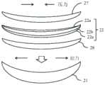
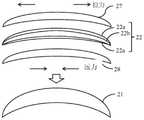
如图1所示,一种习知的光学系统包括显示器1以及光学模块2,显示器1做为光源可发出光线,光学模块2由第一光学镜片21、相位延迟片22、第二光学镜片23、反射式偏振片24、线性偏振片25及第三光学镜片26等光学组件所组成,让显示器1输出的光线经过光学模块2的多次反射和相位调整之后来导出至人眼,以藉由将原本较长的光线路径大幅缩短,使得光学系统的整体体积可以达到最小化。在上述光学模块中,相位延迟片22可以贴合在第一光学镜片21的凹面或第二光学镜片23的凸面上,反射式偏振片24可以贴合在第二光学镜片23的凹面,线性偏振片25可以贴合在第三光学镜片26的凸面上,并可采用曲面光学镜片来替换至少一个光学镜片。以相位延迟片22为例,如图2A所示,相位延迟片22的基本结构是两层TAC(三醋酸纤维)膜22a,夹一层拉伸后的PVA(聚乙烯醇)膜22b,其表面通常贴覆有保护膜(图中未示),在贴合时,是将相位延迟片22先贴上承载膜27,再撕去保护膜,然后以光学胶(OCA)或感压胶(PSA)等胶材28黏贴于第一光学镜片21的凹面上,或者如图2B所示,相位延迟片22可以OCA或PSA等胶材28黏贴于第二光学镜片23的凸面上。As shown in Figure 1, a known optical system includes a
在此先说明所谓「应力中心平面(Neutral Plane)」,其表征材料在弯曲中不会受到拉伸或压缩的一个平面,也就是无应力(stress-free)区域。因此,在结构设计中找出应力中心平面作为应力平衡点,可以保护结构中最需要保护的部位。图3A显示图2A中由多层膜堆栈而成的复合膜片30之受力情况,复合膜片30受弯曲时,上侧受压力作用缩短,下侧受拉力作用伸长,而上侧和下侧之间的断面即为应力中心平面NP,此断面落在相位延迟片22中间的PVA膜22b,在弯曲中既不伸长亦不缩短。图3B显示图2B中由多层膜堆栈而成的复合膜片30之受力情况,复合膜片30受弯曲时,上侧受拉力作用伸长,下侧受压力作用缩短,而上侧和下侧之间的断面为应力中心平面NP,此断面同样落在相位延迟片22中间的PVA膜22b,在弯曲中既不伸长亦不缩短。然而,上述复合膜片30并无应力补偿(stresscompensation)设计,其曲率半径往往无法小于30毫米,否则会对于光学膜的贴合及环境测试良率有影响。上述复合膜片30会产生显微镜无法看到的微裂纹,此微裂纹会提供环境测试中水氧入侵之路径,导致光学膜发生翘曲。再者,若胶材本身的固定能力不够强,遇上光学膜不在应力平衡点时,胶材会固定不住两边的黏着物,此现象在环境测试的高温条件下会更明显被诱发,进而影响生产良率。Here, the so-called "Neutral Plane" is described, which represents a plane where the material will not be stretched or compressed during bending, that is, the stress-free region. Therefore, finding the stress center plane as the stress balance point in the structural design can protect the most protected parts of the structure. Fig. 3 A shows the stress situation of the composite diaphragm 30 formed by stacking multilayer films in Fig. 2A. When the composite diaphragm 30 is bent, the upper side is shortened by pressure, the lower side is elongated by tension, and the upper side and the lower side are stretched. The cross section between the lower sides is the stress center plane NP, which falls on the
是以,要如何对于曲面光学镜片的贴合结构进行改良,来解决上述先前技术之各种缺失,即为从事此行业相关业者所亟欲研发的课题。Therefore, how to improve the bonding structure of the curved optical lens to solve the various deficiencies of the above-mentioned prior art is an urgent research and development topic for those engaged in this industry.
发明内容Contents of the invention
有鉴于此,本发明的主要目的在于提供一种曲面光学镜片的贴合结构及应用其的光学模块,利用在光学膜的一侧增加功能性膜,可以减少光学膜在贴合制程中受到的拉应力破坏,并可缩小曲率半径,从而达到贴合良率的提升。In view of this, the main purpose of the present invention is to provide a bonding structure for curved optical lenses and an optical module using the same. By adding a functional film to one side of the optical film, the impact on the optical film during the bonding process can be reduced. The tensile stress is destroyed, and the radius of curvature can be reduced, so as to improve the bonding yield.
为达上述目的,本发明提供一种曲面光学镜片的贴合结构,其包括有曲面镜片、复合膜片以及复合膜片,复合膜片包括光学膜、第一贴合层、功能性膜及第二贴合层。其中,光学膜贴合于曲面镜片之表面。第一贴合层黏接于曲面镜片和光学膜之间。功能性膜贴合于光学膜与第一贴合层之间或光学膜背向曲面镜片的一面,且第二贴合层黏接于功能性膜与光学膜之间。而承载膜贴合于复合膜片背向曲面镜片的一面。In order to achieve the above-mentioned purpose, the present invention provides a bonding structure for curved optical lenses, which includes curved lenses, a composite film and a composite film, and the composite film includes an optical film, a first bonding layer, a functional film and a second bonding layer. Two bonding layers. Wherein, the optical film is pasted on the surface of the curved lens. The first bonding layer is bonded between the curved lens and the optical film. The functional film is bonded between the optical film and the first bonding layer or the side of the optical film facing away from the curved lens, and the second bonding layer is bonded between the functional film and the optical film. And the carrying film is attached to the side of the composite diaphragm facing away from the curved lens.
根据本发明的实施例,前述的表面为凹面,功能性膜贴合于光学膜与第一贴合层之间。According to an embodiment of the present invention, the aforementioned surface is a concave surface, and the functional film is pasted between the optical film and the first pasting layer.
根据本发明的实施例,前述的表面为凸面,功能性膜贴合于光学膜背向曲面镜片的一面。According to an embodiment of the present invention, the aforementioned surface is a convex surface, and the functional film is bonded to the side of the optical film facing away from the curved lens.
根据本发明的实施例,前述的光学膜为相位延迟片、反射式偏振片或线性偏振片。According to an embodiment of the present invention, the aforementioned optical film is a phase retarder, a reflective polarizer or a linear polarizer.
根据本发明的实施例,前述的光学膜为复数光学膜堆栈而成,这些光学膜为相位延迟片、反射式偏振片和线性偏振片中的至少一种,且在这些光学膜之间是以第三贴合层相互黏接。According to an embodiment of the present invention, the foregoing optical films are formed by stacking a plurality of optical films, and these optical films are at least one of a phase retarder, a reflective polarizer and a linear polarizer, and between these optical films are The third bonding layers are bonded to each other.
根据本发明的实施例,前述的第一贴合层和第二贴合层为光学胶或感压胶。According to an embodiment of the present invention, the aforementioned first bonding layer and the second bonding layer are optical glue or pressure-sensitive glue.
根据本发明的实施例,前述的第一贴合层和第二贴合层的面内相位差值为10-20奈米。According to an embodiment of the present invention, the in-plane phase difference between the aforementioned first bonding layer and the second bonding layer is 10-20 nm.
根据本发明的实施例,前述的功能性膜是由环烯烃聚合物(COP)、无色聚酰亚胺(CPI)、聚碳酸酯(PC)、聚乙烯醇(PVA)、聚芳酯(PAR)、聚砜(PSU)及聚烯烃(PO)中的至少一种薄膜所构成。According to an embodiment of the present invention, the aforementioned functional film is made of cycloolefin polymer (COP), colorless polyimide (CPI), polycarbonate (PC), polyvinyl alcohol (PVA), polyarylate ( PAR), polysulfone (PSU) and polyolefin (PO) at least one film.
根据本发明的实施例,前述的功能性膜的厚度为10-100微米。According to an embodiment of the present invention, the aforementioned functional film has a thickness of 10-100 microns.
根据本发明的实施例,前述的功能性膜的面内相位差值小于30奈米。According to an embodiment of the present invention, the in-plane phase difference of the aforesaid functional film is less than 30 nm.
根据本发明的实施例,前述的功能性膜的穿透率大于90%。According to an embodiment of the present invention, the transmittance of the aforementioned functional film is greater than 90%.
根据本发明的实施例,前述的功能性膜的杨氏模数小于3MPa。According to an embodiment of the present invention, the Young's modulus of the aforementioned functional film is less than 3 MPa.
根据本发明的实施例,前述的功能性膜的至少一侧设置有抗反射镀膜或带通滤波层。According to an embodiment of the present invention, at least one side of the aforementioned functional film is provided with an anti-reflection coating or a band-pass filter layer.
另外,本发明还提供一种光学模块,其用以接收显示器所发出的光线并导入人眼,光学模块包括在显示器前面依次设置的第一曲面镜片、相位延迟片、第二曲面镜片、反射式偏振片、线性偏振片和第三曲面镜片,且光学模块进而包括依据下列条件(1)、(2)、(3)、(4)、(5)或(6)配置的承载膜、第一贴合层、功能性膜和第二贴合层:In addition, the present invention also provides an optical module, which is used to receive the light emitted by the display and guide it into human eyes. The optical module includes a first curved lens, a phase retarder, a second curved lens, a reflective A polarizer, a linear polarizer, and a third curved lens, and the optical module further includes a carrier film configured according to the following conditions (1), (2), (3), (4), (5) or (6), the first Lamination layer, functional film and second lamination layer:
(1)相位延迟片贴合于第一曲面镜片面向第二曲面镜片的一面;(1) The phase retarder is bonded to the side of the first curved lens facing the second curved lens;
承载膜贴合于相位延迟片背向第一曲面镜片的一面;The carrier film is attached to the side of the phase retarder facing away from the first curved lens;
第一贴合层黏接于第一曲面镜片和相位延迟片之间;The first bonding layer is bonded between the first curved lens and the phase retarder;
功能性膜贴合于相位延迟片与第一贴合层之间;以及The functional film is bonded between the phase retarder and the first bonding layer; and
第二贴合层黏接于功能性膜与相位延迟片之间;The second bonding layer is bonded between the functional film and the phase retarder;
(2)相位延迟片贴合于第二曲面镜片面向第一曲面镜片的一面;(2) The phase retarder is bonded to the side of the second curved lens facing the first curved lens;
承载膜贴合于相位延迟片背向第二曲面镜片的一面;The carrier film is attached to the side of the phase retarder facing away from the second curved lens;
第一贴合层黏接于第二曲面镜片和相位延迟片之间;The first bonding layer is bonded between the second curved lens and the phase retarder;
功能性膜贴合于相位延迟片背向第二曲面镜片的一面;以及The functional film is attached to the side of the phase retarder facing away from the second curved lens; and
第二贴合层黏接于功能性膜与相位延迟片之间;The second bonding layer is bonded between the functional film and the phase retarder;
(3)反射式偏振片贴合于第二曲面镜片背向第一曲面镜片的一面;(3) The reflective polarizer is attached to the side of the second curved lens facing away from the first curved lens;
承载膜贴合于反射式偏振片背向第二曲面镜片的一面;The carrier film is attached to the side of the reflective polarizer facing away from the second curved lens;
第一贴合层黏接于第二曲面镜片和反射式偏振片之间;The first bonding layer is bonded between the second curved lens and the reflective polarizer;
功能性膜贴合于反射式偏振片与第一贴合层之间;以及a functional film is bonded between the reflective polarizer and the first bonding layer; and
第二贴合层黏接于功能性膜与反射式偏振片之间;The second bonding layer is bonded between the functional film and the reflective polarizer;
(4)线性偏振片贴合于第三曲面镜片面向第二曲面镜片的一面;(4) The linear polarizer is attached to the side of the third curved lens facing the second curved lens;
承载膜贴合于线性偏振片背向第三曲面镜片的一面;The carrier film is attached to the side of the linear polarizer facing away from the third curved lens;
第一贴合层黏接于第三曲面镜片和线性偏振片之间;The first bonding layer is bonded between the third curved lens and the linear polarizer;
功能性膜贴合于线性偏振片背向第三曲面镜片的一面;以及The functional film is attached to the side of the linear polarizer facing away from the third curved lens; and
第二贴合层黏接于功能性膜与线性偏振片之间;The second bonding layer is bonded between the functional film and the linear polarizer;
(5)反射式偏振片和线性偏振片之间是以第三贴合层相互黏接,且贴合于第二曲面镜片背向第一曲面镜片的一面;(5) The reflective polarizer and the linear polarizer are bonded to each other by a third bonding layer, and bonded to the side of the second curved lens facing away from the first curved lens;
承载膜贴合于线性偏振片背向第二曲面镜片的一面;The carrier film is attached to the side of the linear polarizer facing away from the second curved lens;
第一贴合层黏接于第二曲面镜片和反射式偏振片之间;The first bonding layer is bonded between the second curved lens and the reflective polarizer;
功能性膜贴合于反射式偏振片与第一贴合层之间;以及a functional film is bonded between the reflective polarizer and the first bonding layer; and
第二贴合层黏接于功能性膜与反射式偏振片之间;The second bonding layer is bonded between the functional film and the reflective polarizer;
(6)反射式偏振片和线性偏振片之间是以第三贴合层相互黏接,且贴合于第三曲面镜片面向第二曲面镜片的一面;(6) The reflective polarizer and the linear polarizer are bonded to each other by a third bonding layer, and bonded to the side of the third curved lens facing the second curved lens;
承载膜贴合于线性偏振片背向第三曲面镜片的一面;The carrier film is attached to the side of the linear polarizer facing away from the third curved lens;
第一贴合层黏接于第三曲面镜片和线性偏振片之间;The first bonding layer is bonded between the third curved lens and the linear polarizer;
功能性膜贴合反射式偏振片背向第三曲面镜片的一面;以及The functional film is bonded to the side of the reflective polarizer facing away from the third curved lens; and
第二贴合层黏接于功能性膜与反射式偏振片之间。The second bonding layer is bonded between the functional film and the reflective polarizer.
根据本发明的实施例,前述的第一曲面镜片、第二曲面镜片和第三曲面镜片的凸面朝向显示器,凹面朝向人眼。According to an embodiment of the present invention, the convex surfaces of the aforementioned first curved lens, the second curved lens and the third curved lens face the display, and the concave surfaces face human eyes.
根据本发明的实施例,前述的第一贴合层和第二贴合层为光学胶或感压胶。According to an embodiment of the present invention, the aforementioned first bonding layer and the second bonding layer are optical glue or pressure-sensitive glue.
根据本发明的实施例,前述的第一贴合层和第二贴合层的面内相位差值为10-20奈米。According to an embodiment of the present invention, the in-plane phase difference between the aforementioned first bonding layer and the second bonding layer is 10-20 nm.
根据本发明的实施例,前述的功能性膜是由环烯烃聚合物(COP)、无色聚酰亚胺(CPI)、聚碳酸酯(PC)、聚乙烯醇(PVA)、聚芳酯(PAR)、聚砜(PSU)及聚烯烃(PO)中的至少一种薄膜所构成。According to an embodiment of the present invention, the aforementioned functional film is made of cycloolefin polymer (COP), colorless polyimide (CPI), polycarbonate (PC), polyvinyl alcohol (PVA), polyarylate ( PAR), polysulfone (PSU) and polyolefin (PO) at least one film.
根据本发明的实施例,前述的功能性膜的厚度为10-100微米。According to an embodiment of the present invention, the aforementioned functional film has a thickness of 10-100 microns.
根据本发明的实施例,前述的功能性膜的面内相位差值小于30奈米。According to an embodiment of the present invention, the in-plane phase difference of the aforesaid functional film is less than 30 nm.
根据本发明的实施例,前述的功能性膜的穿透率大于90%。According to an embodiment of the present invention, the transmittance of the aforementioned functional film is greater than 90%.
根据本发明的实施例,前述的功能性膜的杨氏模数小于3MPa。According to an embodiment of the present invention, the Young's modulus of the aforementioned functional film is less than 3 MPa.
根据本发明的实施例,前述的功能性膜的至少一侧设置有抗反射镀膜或带通滤波层。According to an embodiment of the present invention, at least one side of the aforementioned functional film is provided with an anti-reflection coating or a band-pass filter layer.
发明有益效果:与先前技术相比,本发明具有以下优势:Beneficial effects of the invention: compared with the prior art, the present invention has the following advantages:
(1)本发明能够突破现有的进行曲面贴合的复合膜片中缺乏应力补偿的设计而得面临光学膜容易翘曲、剥落的情况,进而导致生产良率不佳的问题。(1) The present invention can break through the lack of stress compensation design in the existing composite diaphragms for curved surface lamination, and face the situation that the optical film is easy to warp and peel off, which in turn leads to the problem of poor production yield.
(2)本发明在复合膜片中将光学膜的一侧增加功能性膜来调整应力平衡点,使得光学膜在贴合制程中的拉应力破坏获得有效减少,且可缩小曲率半径,而可对于光学膜的贴合及环境测试良率有所提升,从而大幅提高其产品的可靠度。(2) The present invention adds a functional film to one side of the optical film in the composite film to adjust the stress balance point, so that the tensile stress damage of the optical film in the bonding process is effectively reduced, and the radius of curvature can be reduced. The lamination of optical films and the yield rate of environmental testing have been improved, thereby greatly improving the reliability of its products.
底下藉由具体实施例详加说明,当更容易了解本发明之目的、技术内容、特点及其所达成之功效。In the following detailed description by means of specific embodiments, it will be easier to understand the purpose, technical content, characteristics and effects of the present invention.
附图说明Description of drawings
图1为先前技术所提供的一种光学系统的布局示意图。FIG. 1 is a schematic layout diagram of an optical system provided by the prior art.
图2A和图2B为先前技术所提供的两种曲面光学镜片的贴合结构的贴合情况示意图。FIG. 2A and FIG. 2B are schematic diagrams of the lamination of two types of lamination structures of curved optical lenses provided by the prior art.
图3A和图3B分别为图2A和图2B中复合膜片之受力情况示意图。FIG. 3A and FIG. 3B are schematic diagrams of the stress on the composite membrane in FIG. 2A and FIG. 2B respectively.
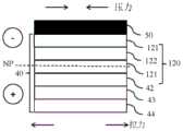
图4A为本发明之第一实施例所提供的复合膜片的剖面图。Fig. 4A is a cross-sectional view of the composite membrane provided by the first embodiment of the present invention.
图4B为本发明之第一实施例所提供的曲面光学镜片的贴合结构的贴合情况示意图。FIG. 4B is a schematic diagram of the lamination of the lamination structure of the curved optical lenses provided by the first embodiment of the present invention.
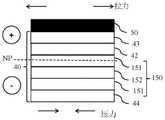
图5A为本发明之第二实施例所提供的复合膜片的剖面图。FIG. 5A is a cross-sectional view of the composite membrane provided by the second embodiment of the present invention.
图5B为本发明之第二实施例所提供的曲面光学镜片的贴合结构的贴合情况示意图。FIG. 5B is a schematic diagram of the lamination of the lamination structure of the curved optical lens provided by the second embodiment of the present invention.
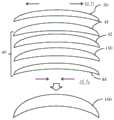
图6为本发明之第三实施例至第八实施例所提供的光学模块的布局示意图。FIG. 6 is a schematic layout diagram of optical modules provided by the third embodiment to the eighth embodiment of the present invention.
图7A为本发明之第三实施例中相位延迟片贴合于第一曲面镜片的示意图。FIG. 7A is a schematic diagram of a phase retarder bonded to a first curved lens according to a third embodiment of the present invention.
图7B为图7A中包含相位延迟片之复合膜片的受力情况示意图。FIG. 7B is a schematic diagram of the stress on the composite diaphragm including the phase retarder in FIG. 7A .
图8A为本发明之第四实施例中相位延迟片贴合于第二曲面镜片的示意图。FIG. 8A is a schematic diagram of a phase retarder attached to a second curved lens in the fourth embodiment of the present invention.
图8B为图8A中包含相位延迟片之复合膜片的受力情况示意图。FIG. 8B is a schematic diagram of the stress on the composite diaphragm including the phase retarder in FIG. 8A .
图9A为本发明之第五实施例中反射式偏振片贴合于第二曲面镜片的示意图。FIG. 9A is a schematic diagram of a reflective polarizer attached to a second curved lens in the fifth embodiment of the present invention.
图9B为图9A中包含反射式偏振片之复合膜片的受力情况示意图。FIG. 9B is a schematic diagram of the stress on the composite membrane including the reflective polarizer in FIG. 9A .
图10A为本发明之第六实施例中线性偏振片贴合于第三曲面镜片的示意图。FIG. 10A is a schematic diagram of a linear polarizer attached to a third curved lens in the sixth embodiment of the present invention.
图10B为图10A中包含线性偏振片之复合膜片的受力情况示意图。FIG. 10B is a schematic diagram of the stress on the composite membrane including the linear polarizer in FIG. 10A .
图11A为本发明之第七实施例中反射式偏振片和线性偏振片贴合于第二曲面镜片的示意图。11A is a schematic diagram of a reflective polarizer and a linear polarizer attached to a second curved lens according to the seventh embodiment of the present invention.
图11B为图11A中包含反射式偏振片和线性偏振片之复合膜片的受力情况示意图。FIG. 11B is a schematic diagram of the stress on the composite membrane including the reflective polarizer and the linear polarizer in FIG. 11A .
图12A为本发明之第八实施例中反射式偏振片和线性偏振片贴合于第三曲面镜片的示意图。FIG. 12A is a schematic diagram of a reflective polarizer and a linear polarizer attached to a third curved lens according to the eighth embodiment of the present invention.
图12B为图12A中包含反射式偏振片和线性偏振片之复合膜片的受力情况示意图。FIG. 12B is a schematic diagram of the stress on the composite membrane including the reflective polarizer and the linear polarizer in FIG. 12A .
附图标记:Reference signs:
1…显示器 30…复合膜片1…Display 30…Composite diaphragm
2…光学模块 40…复合膜片2…
21…第一光学镜片 41…光学膜21...first
22…相位延迟片 42…第二贴合层22...
22a…TAC膜 43…功能性膜22a...
22b…PVA膜 44…第一贴合层22b...
23…第二光学镜片 45…保护膜23…second
24…反射式偏振片 46…第三贴合层24...
25…线性偏振片 50…承载膜25…
26…第三光学镜片 60…曲面镜片26…Third
27…承载膜 70…人眼27…
28…胶材 100…光学模块28…
110…第一曲面镜片 150…线性偏振片110…first
120…相位延迟片 151…TAC膜120...
121…TAC膜 152…PVA膜121...
122…PVA膜 160…第三曲面镜片122…
130…第二曲面镜片 NP…应力中心平面130…second curved lens NP…stress central plane
140…反射式偏振片140…reflective polarizer
具体实施方式Detailed ways
本发明的实施例将藉由下文配合相关附图进一步加以解说。尽可能的,于附图与说明书中,相同标号系代表相同或相似构件。于附图中,基于简化与方便标示,形状与厚度可能经过夸大表示。可以理解的是,未特别显示于附图中或描述于说明书中之组件,为所属技术领域中具有通常知识者所知之形态。本领域中具有通常知识者可依据本发明之内容而进行多种之改变与修改。Embodiments of the present invention will be further explained in conjunction with the accompanying drawings below. Wherever possible, the same reference numerals represent the same or similar components throughout the drawings and description. In the drawings, the shape and thickness may be exaggerated for simplification and convenient labeling. It can be understood that components not particularly shown in the drawings or described in the specification are forms known to those skilled in the art. Those skilled in the art can make various changes and modifications according to the content of the present invention.
需要说明,本发明实施例中所有方向性指示(诸如上、下、左、右、前、后……)仅用于解释在某一特定姿态(如附图所示)下各部件之间的相对位置关系、运动情况等,如果该特定姿态发生改变时,则该方向性指示也相应地随之改变。It should be noted that all directional indications (such as up, down, left, right, front, back...) in the embodiments of the present invention are only used to explain the relationship between the components in a certain posture (as shown in the accompanying drawings). Relative positional relationship, movement conditions, etc., if the specific posture changes, the directional indication will also change accordingly.
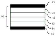
请参照图4A和图4B。图4A为本发明之第一实施例所提供的复合膜片的剖面图;图4B为本发明之第一实施例所提供的曲面光学镜片的贴合结构的贴合情况示意图。于本实施例中,复合膜片40由上而下依序包括光学膜41、第二贴合层42、功能性膜43及第一贴合层44,如图4A所示,复合膜片40在使用前,其表面通常贴覆有保护膜45,作为暂时性防护作用。进行贴合制程时,则将保护膜45撕去,如图4B所示,将光学膜41背向功能性膜43的一面贴上承载膜50,然后,以第一贴合层44黏贴于曲面镜片60的表面上。详细而言,本实施例之曲面光学镜片的贴合结构包括曲面镜片60以及贴合于曲面镜片60表面的复合膜片40,并在复合膜片40背向曲面镜片60的一面贴合有承载膜50。于本实施例中,光学膜41贴合于曲面镜片60之凹面,第一贴合层44黏接于曲面镜片60和光学膜41之间,功能性膜43贴合于光学膜41与第一贴合层44之间,且第二贴合层42黏接于功能性膜43与光学膜41之间。Please refer to FIG. 4A and FIG. 4B. FIG. 4A is a cross-sectional view of the composite membrane provided by the first embodiment of the present invention; FIG. 4B is a schematic view of the lamination of the lamination structure of the curved optical lens provided by the first embodiment of the present invention. In this embodiment, the
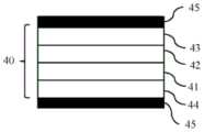
请参照图5A和图5B。图5A为本发明之第二实施例所提供的复合膜片的剖面图;图5B为本发明之第二实施例所提供的曲面光学镜片的贴合结构的贴合情况示意图。于本实施例中,复合膜片40由上而下依序包括功能性膜43、第二贴合层42、光学膜41及第一贴合层44,如图5A所示,复合膜片40在使用前同样贴覆有保护膜45,并在贴合制程时,将保护膜45撕去。再如图5B所示,将功能性膜43背向光学膜41的一面贴上承载膜50,然后,以第一贴合层44黏贴于曲面镜片60的表面上。详细而言,本实施例之曲面光学镜片的贴合结构包括曲面镜片60以及贴合于曲面镜片60表面的复合膜片40,并在复合膜片40背向曲面镜片60的一面贴合有承载膜50。于本实施例中,光学膜41贴合于曲面镜片60之凸面,第一贴合层44黏接于曲面镜片60和光学膜41之间,功能性膜43贴合于光学膜41背向曲面镜片60的一面,且第二贴合层42黏接于功能性膜43与光学膜41之间。Please refer to FIG. 5A and FIG. 5B . Fig. 5A is a cross-sectional view of the composite membrane provided by the second embodiment of the present invention; Fig. 5B is a schematic diagram of the lamination of the lamination structure of the curved optical lens provided by the second embodiment of the present invention. In this embodiment, the
进一步地,在一些实施例中,本发明所使用的光学膜41可为单层光学膜,例如,光学膜可为相位延迟片、反射式偏振片或线性偏振片;光学膜41亦可由复数光学膜41堆栈而成,这些光学膜41可为相位延迟片、反射式偏振片和线性偏振片中的至少一种,且在这些光学膜41之间是以第三贴合层相互黏接(见第七、第八实施例)。Further, in some embodiments, the
在一些实施例中,本发明所使用的第一贴合层44和第二贴合层42可为光学胶或感压胶。较佳而言,本发明所使用的第一贴合层44和第二贴合层42的面内相位差值(R)为10-20奈米。In some embodiments, the first
在一些实施例中,本发明所使用的功能性膜43可由环烯烃聚合物(COP)、无色聚酰亚胺(CPI)、聚碳酸酯(PC)、聚乙烯醇(PVA)、聚芳酯(PAR)、聚砜(PSU)及聚烯烃(PO)中的至少一种薄膜所构成。在一些实施例中,本发明所使用的功能性膜43的厚度为10-100微米。值得说明的是,本发明所使用的功能性膜43的面内相位差值越小越好,基本上要小于30奈米,较佳为小于20奈米,甚至可趋近或等于0。本发明所使用的功能性膜43的穿透率(T%)大于90%。同样值得说明的是,本发明所使用的功能性膜43的杨氏模数(Young's modulus)越小越好,基本上要小于3MPa,甚至可趋近为0。另外,本发明可于功能性膜43的至少一侧设置有抗反射镀膜或带通滤波层。In some embodiments, the
接续请参照图6,其为本发明之第三实施例至第八实施例所提供的光学模块的布局示意图。在第三实施例至第八实施例中,光学模块100是用以接收显示器1所发出的光线并导入人眼70以进行成像,光学模块100包括在显示器1前面依次设置的第一曲面镜片110、相位延迟片120、第二曲面镜片130、反射式偏振片140、线性偏振片150和第三曲面镜片160;其中,第一曲面镜片110、第二曲面镜片130和第三曲面镜片160的凸面朝向显示器1,凹面朝向人眼70。且第三实施例至第八实施例之光学模块100进一步分别配置有承载膜50、第一贴合层44、功能性膜43和第二贴合层42。Please refer to FIG. 6 , which is a schematic layout diagram of the optical modules provided by the third embodiment to the eighth embodiment of the present invention. In the third embodiment to the eighth embodiment, the
请参照图7A和图7B。图7A为本发明之第三实施例中相位延迟片贴合于第一曲面镜片的示意图;图7B为图7A中包含相位延迟片之复合膜片的受力情况示意图。本实施例是将相位延迟片120贴合于第一曲面镜片110的凹面上而成为一体。如图7A所示,相位延迟片120贴合于第一曲面镜片110面向第二曲面镜片130的一面,承载膜50贴合于相位延迟片120背向第一曲面镜片110的一面,第一贴合层44黏接于第一曲面镜片110和相位延迟片120之间,功能性膜43贴合于相位延迟片120与第一贴合层44之间,而第二贴合层42黏接于功能性膜43与相位延迟片120之间。如图7B所示,本实施例的相位延迟片120是两层TAC膜121夹一层拉伸后的PVA膜122,复合膜片40受弯曲时,上侧受压力作用缩短,下侧受拉力作用伸长,而上侧和下侧之间的断面为应力中心平面NP,在弯曲中既不伸长亦不缩短。相较于先前技术中应力中心平面NP为相位延迟片22中间的PVA膜22b(见图3A),本实施例之应力中心平面NP下移,而落在PVA膜122下方的TAC膜121,可以降低相位延迟片120在弯曲时所受到的拉应力。Please refer to FIG. 7A and FIG. 7B . FIG. 7A is a schematic diagram of the phase retarder attached to the first curved lens in the third embodiment of the present invention; FIG. 7B is a schematic diagram of the force of the composite film including the phase retarder in FIG. 7A. In this embodiment, the
请参照图8A和图8B。图8A为本发明之第四实施例中相位延迟片贴合于第二曲面镜片的示意图;图8B为图8A中包含相位延迟片之复合膜片的受力情况示意图。本实施例是将相位延迟片120贴合于第二曲面镜片130的凸面上而成为一体。如图8A所示,相位延迟片120贴合于第二曲面镜片130面向第一曲面镜片110(见图6)的一面,承载膜50贴合于相位延迟片120背向第二曲面镜片130的一面,第一贴合层44黏接于第二曲面镜片130和相位延迟片120之间,功能性膜43贴合于相位延迟片120背向第二曲面镜片130的一面,而第二贴合层42黏接于功能性膜43与相位延迟片120之间。如图8B所示,本实施例的相位延迟片120是两层TAC膜121夹一层拉伸后的PVA膜122,复合膜片40受弯曲时,上侧受拉力作用伸长,下侧受压力作用缩短,而上侧和下侧之间的应力中心平面NP在弯曲中既不伸长亦不缩短。相较于先前技术中应力中心平面NP为相位延迟片22中间的PVA膜22b(见图3B),本实施例之应力中心平面NP上移,而落在PVA膜122上方的TAC膜121,可以降低相位延迟片120在弯曲时所受到的拉应力。Please refer to FIG. 8A and FIG. 8B. FIG. 8A is a schematic diagram of the phase retarder attached to the second curved lens in the fourth embodiment of the present invention; FIG. 8B is a schematic diagram of the force of the composite film including the phase retarder in FIG. 8A . In this embodiment, the
请参照图9A和图9B。图9A为本发明之第五实施例中反射式偏振片贴合于第二曲面镜片的示意图;图9B为图9A中包含反射式偏振片之复合膜片的受力情况示意图。本实施例是将反射式偏振片140贴合于第二曲面镜片130的凹面上而成为一体。如图9A所示,反射式偏振片140贴合于第二曲面镜片130背向第一曲面镜片110的一面,承载膜50贴合于反射式偏振片140背向第二曲面镜片130(见图6)的一面,第一贴合层44黏接于第二曲面镜片130和反射式偏振片140之间,功能性膜43贴合于反射式偏振片140与第一贴合层44之间,而第二贴合层42黏接于功能性膜43与反射式偏振片140之间。如图9B所示,本实施例的复合膜片40受弯曲时,上侧受压力作用缩短,下侧受拉力作用伸长,而上侧和下侧之间的应力中心平面NP,在弯曲中既不伸长亦不缩短。相较于先前技术中应力中心平面NP落在光学膜(相位延迟片22)中间位置(见图3A),本实施例之应力中心平面NP下移,而落在反射式偏振片140下方的第二贴合层42,可以降低反射式偏振片140在弯曲时所受到的拉应力。Please refer to FIG. 9A and FIG. 9B . FIG. 9A is a schematic diagram of the reflective polarizer attached to the second curved lens in the fifth embodiment of the present invention; FIG. 9B is a schematic diagram of the force of the composite film including the reflective polarizer in FIG. 9A . In this embodiment, the
请参照图10A和图10B。图10A为本发明之第六实施例中线性偏振片贴合于第三曲面镜片的示意图;图10B为图10A中包含线性偏振片之复合膜片的受力情况示意图。本实施例是将线性偏振片150贴合于第三曲面镜片160的凸面上而成为一体。如图10A所示,线性偏振片150贴合于第三曲面镜片160面向第二曲面镜片130(见图6)的一面,承载膜50贴合于线性偏振片150背向第三曲面镜片160的一面,第一贴合层44黏接于第三曲面镜片160和线性偏振片150之间,功能性膜43贴合于线性偏振片150背向第三曲面镜片160的一面,而第二贴合层42黏接于功能性膜43与线性偏振片150之间。如图10B所示,本实施例的线性偏振片150是两层TAC膜151夹一层拉伸后的PVA膜152,复合膜片40受弯曲时,上侧受拉力作用伸长,下侧受压力作用缩短,而上侧和下侧之间的应力中心平面NP,在弯曲中既不伸长亦不缩短。相较于先前技术中应力中心平面NP为相位延迟片22中间的PVA膜22b(见图3B),本实施例之应力中心平面NP上移,而落在PVA膜152上方的TAC膜151,可以降低线性偏振片150在弯曲时所受到的拉应力。Please refer to FIG. 10A and FIG. 10B . FIG. 10A is a schematic diagram of a linear polarizer attached to a third curved lens in the sixth embodiment of the present invention; FIG. 10B is a schematic diagram of the stress on the composite film including a linear polarizer in FIG. 10A . In this embodiment, the
请参照图11A和图11B。图11A为本发明之第七实施例中反射式偏振片和线性偏振片贴合于第二曲面镜片的示意图;图11B为图11A中包含反射式偏振片和线性偏振片之复合膜片的受力情况示意图。本实施例是将反射式偏振片140和线性偏振片150贴合于第二曲面镜片130的凹面上而成为一体。如图11A所示,反射式偏振片140和线性偏振片150之间是以第三贴合层46相互黏接,且贴合于第二曲面镜片130背向第一曲面镜片110(见图6)的一面,承载膜50贴合于线性偏振片150背向第二曲面镜片130的一面,第一贴合层44黏接于第二曲面镜片130和反射式偏振片140之间,功能性膜43贴合于反射式偏振片140与第一贴合层44之间,而第二贴合层42黏接于功能性膜43与反射式偏振片140之间。如图11B所示,本实施例的复合膜片40受弯曲时,上侧受压力作用缩短,下侧受拉力作用伸长,而上侧和下侧之间的应力中心平面NP在弯曲中既不伸长亦不缩短。相较于先前技术中应力中心平面NP落在光学膜(相位延迟片22)中间位置(见图3A),相当于本实施例中反射式偏振片140和线性偏振片150之间的第三贴合层46的位置,本实施例之应力中心平面NP下移,而落在第三贴合层46下方的反射式偏振片140,可以降低反射式偏振片140和线性偏振片150在弯曲时所受到的拉应力。Please refer to FIG. 11A and FIG. 11B . Fig. 11A is a schematic diagram of a reflective polarizer and a linear polarizer attached to a second curved lens in the seventh embodiment of the present invention; Schematic diagram of the power situation. In this embodiment, the
请参照图12A和图12B。图12A为本发明之第八实施例中反射式偏振片和线性偏振片贴合于第三曲面镜片的示意图;图12B为图12A中包含反射式偏振片和线性偏振片之复合膜片的受力情况示意图。本实施例是将反射式偏振片140和和线性偏振片150贴合于第三曲面镜片160的凸面上而成为一体。如图12A所示,反射式偏振片140和线性偏振片150之间是以第三贴合层46相互黏接,且贴合于第三曲面镜片160面向第二曲面镜片130(见图6)的一面,承载膜50贴合于线性偏振片150背向第三曲面镜片160的一面,第一贴合层44黏接于第三曲面镜片160和线性偏振片150之间,功能性膜43贴合于线性偏振片150背向第三曲面镜片160的一面,而第二贴合层42黏接于功能性膜43与反射式偏振片140之间。如图12B所示,本实施例的复合膜片40受弯曲时,上侧受拉力作用伸长,下侧受压力作用缩短,而上侧和下侧之间的应力中心平面NP,在弯曲中既不伸长亦不缩短。相较于先前技术中应力中心平面NP为相位延迟片22中间的PVA膜22b(见图3B),相当于本实施例中反射式偏振片140和线性偏振片150之间的第三贴合层46的位置,本实施例之应力中心平面NP上移,而落在第三贴合层46上方的反射式偏振片140,可以降低反射式偏振片140和线性偏振片150在弯曲时所受到的拉应力。Please refer to Figure 12A and Figure 12B. Fig. 12A is a schematic diagram of the reflective polarizer and linear polarizer attached to the third curved lens in the eighth embodiment of the present invention; Schematic diagram of the power situation. In this embodiment, the
基于上面所说明的,本发明利用在包含相位延迟片、反射式偏振片或/及线性偏振片的光学膜的一侧设置有功能性膜,此功能性膜的增设有助于调整复合膜片结构中的应力平衡点,可以降低光学膜在贴合制程中所受到的拉应力,避免光学膜发生翘曲最终导致脱离甚至掉落的情况,从而可大幅提高产品的可靠度,并延长使用寿命。Based on the above description, the present invention utilizes a functional film on one side of the optical film comprising a phase retarder, a reflective polarizer or/and a linear polarizer, and the addition of this functional film helps to adjust the composite film The stress balance point in the structure can reduce the tensile stress on the optical film during the bonding process, avoid warping of the optical film and eventually lead to detachment or even drop, thus greatly improving the reliability of the product and prolonging the service life .
进一步就两光学膜的合并来说,先前技术通常是将两片光学膜分别贴在两个光学镜片上,再将两个光学镜片组合成一个半成品。本发明则利用将两片光学膜以第三贴合层合并的复合膜片,而可以达到减少贴合制程中的一次步骤,同时,可合并两片光学膜的QC(质量管理),可减少料号,提升贴合良率。As far as the merging of two optical films is concerned, in the prior art, two optical films are respectively pasted on two optical lenses, and then the two optical lenses are combined into a semi-finished product. The present invention utilizes a composite film that combines two optical films with the third lamination layer to reduce one step in the lamination process. At the same time, the QC (quality control) of two optical films can be combined, which can reduce Part number, improve the bonding yield.
唯以上所述者,仅为本发明之较佳实施例而已,并非用来限定本发明实施之范围。故即凡依本发明申请范围所述之特征及精神所为之均等变化或修饰,均应包括于本发明之申请专利范围内。The above descriptions are only preferred embodiments of the present invention, and are not intended to limit the scope of the present invention. Therefore, all equivalent changes or modifications based on the features and spirit described in the scope of the application of the present invention shall be included in the scope of the patent application of the present invention.
Claims (23)
Translated fromChinesePriority Applications (2)
| Application Number | Priority Date | Filing Date | Title |
|---|---|---|---|
| CN202211439657.9ACN115857133A (en) | 2022-11-17 | 2022-11-17 | Laminating structure of curved surface optical lens and optical module applying same |
| TW111144400ATWI828432B (en) | 2022-11-17 | 2022-11-21 | Bonding structure of curved optical lens and applied optical module thereof |
Applications Claiming Priority (1)
| Application Number | Priority Date | Filing Date | Title |
|---|---|---|---|
| CN202211439657.9ACN115857133A (en) | 2022-11-17 | 2022-11-17 | Laminating structure of curved surface optical lens and optical module applying same |
Publications (1)
| Publication Number | Publication Date |
|---|---|
| CN115857133Atrue CN115857133A (en) | 2023-03-28 |
Family
ID=85663858
Family Applications (1)
| Application Number | Title | Priority Date | Filing Date |
|---|---|---|---|
| CN202211439657.9APendingCN115857133A (en) | 2022-11-17 | 2022-11-17 | Laminating structure of curved surface optical lens and optical module applying same |
Country Status (2)
| Country | Link |
|---|---|
| CN (1) | CN115857133A (en) |
| TW (1) | TWI828432B (en) |
Citations (10)
| Publication number | Priority date | Publication date | Assignee | Title |
|---|---|---|---|---|
| US20040125339A1 (en)* | 2002-12-27 | 2004-07-01 | Phillips Richard A. | Thermoformable polarized lens with substrate having adjusted glass transition temperature |
| JP2009198580A (en)* | 2008-02-19 | 2009-09-03 | Maguteiku:Kk | Manufacturing method for polarizing lens and polarizing lens |
| CN102639315A (en)* | 2009-11-02 | 2012-08-15 | 埃西勒国际通用光学公司 | Tri-layer adhesive system for a laminated lens and method for applying same |
| CN106501881A (en)* | 2015-09-03 | 2017-03-15 | 3M创新有限公司 | The method for making blooming and Optical stack |
| CN108603965A (en)* | 2016-01-29 | 2018-09-28 | 日东电工株式会社 | Optical laminate |
| CN109073916A (en)* | 2016-04-28 | 2018-12-21 | 卡尔蔡司光学国际有限公司 | High Refractive Index Polarized Spectacle Lenses |
| CN110088672A (en)* | 2016-12-20 | 2019-08-02 | 3M创新有限公司 | Optical system |
| CN111344613A (en)* | 2017-10-09 | 2020-06-26 | 3M创新有限公司 | Optical Components and Optical Systems |
| CN113954447A (en)* | 2021-11-01 | 2022-01-21 | 业成科技(成都)有限公司 | Optical film attaching method, optical element and electronic device |
| CN114839781A (en)* | 2022-05-26 | 2022-08-02 | 业成科技(成都)有限公司 | Head-mounted display |
Family Cites Families (3)
| Publication number | Priority date | Publication date | Assignee | Title |
|---|---|---|---|---|
| US20060228559A1 (en)* | 2005-04-06 | 2006-10-12 | 3M Innovative Properties Company | Optical bodies with optical films having specific functional layers |
| CN201707518U (en)* | 2010-05-29 | 2011-01-12 | 比亚迪股份有限公司 | Unidirectional perspective dimmer membrane and dimmer glass |
| JP7565162B2 (en)* | 2020-03-27 | 2024-10-10 | 日東電工株式会社 | Image display device |
- 2022
- 2022-11-17CNCN202211439657.9Apatent/CN115857133A/enactivePending
- 2022-11-21TWTW111144400Apatent/TWI828432B/enactive
Patent Citations (10)
| Publication number | Priority date | Publication date | Assignee | Title |
|---|---|---|---|---|
| US20040125339A1 (en)* | 2002-12-27 | 2004-07-01 | Phillips Richard A. | Thermoformable polarized lens with substrate having adjusted glass transition temperature |
| JP2009198580A (en)* | 2008-02-19 | 2009-09-03 | Maguteiku:Kk | Manufacturing method for polarizing lens and polarizing lens |
| CN102639315A (en)* | 2009-11-02 | 2012-08-15 | 埃西勒国际通用光学公司 | Tri-layer adhesive system for a laminated lens and method for applying same |
| CN106501881A (en)* | 2015-09-03 | 2017-03-15 | 3M创新有限公司 | The method for making blooming and Optical stack |
| CN108603965A (en)* | 2016-01-29 | 2018-09-28 | 日东电工株式会社 | Optical laminate |
| CN109073916A (en)* | 2016-04-28 | 2018-12-21 | 卡尔蔡司光学国际有限公司 | High Refractive Index Polarized Spectacle Lenses |
| CN110088672A (en)* | 2016-12-20 | 2019-08-02 | 3M创新有限公司 | Optical system |
| CN111344613A (en)* | 2017-10-09 | 2020-06-26 | 3M创新有限公司 | Optical Components and Optical Systems |
| CN113954447A (en)* | 2021-11-01 | 2022-01-21 | 业成科技(成都)有限公司 | Optical film attaching method, optical element and electronic device |
| CN114839781A (en)* | 2022-05-26 | 2022-08-02 | 业成科技(成都)有限公司 | Head-mounted display |
Also Published As
| Publication number | Publication date |
|---|---|
| TW202421443A (en) | 2024-06-01 |
| TWI828432B (en) | 2024-01-01 |
Similar Documents
| Publication | Publication Date | Title |
|---|---|---|
| JP5332599B2 (en) | Polarizing plate, manufacturing method thereof, and composite polarizing plate using the same | |
| KR102243206B1 (en) | Flexible display device | |
| US12259758B2 (en) | Display device | |
| CN106054437B (en) | Polarizing film set with adhesive layer, liquid crystal panel and liquid crystal display device | |
| JP7542967B2 (en) | Laminate | |
| CN204925436U (en) | Polaroid and have touch -sensitive display device of this polaroid | |
| CN108732811A (en) | Display device | |
| CN105717571A (en) | Polarizing film, manufacturing method thereof, polarizing film set, liquid crystal display panel and liquid crystal display device | |
| JP2010078678A (en) | Display device | |
| JP6323477B2 (en) | Polarizing plate set and LCD panel | |
| JP2025094229A (en) | Method for manufacturing glass resin laminate | |
| CN114514452A (en) | Optical film | |
| TWI736968B (en) | Optical film group and optical laminate | |
| CN115857133A (en) | Laminating structure of curved surface optical lens and optical module applying same | |
| CN108351460B (en) | Polarizing plate and liquid crystal display device | |
| WO2018094729A1 (en) | Touch panel and flexible display | |
| JP2013122530A (en) | Composite polarizing plate set, liquid crystal panel, and liquid crystal display device | |
| US12426483B2 (en) | Display panel and display device | |
| JP5550869B2 (en) | Liquid crystal display | |
| CN111512198B (en) | Polarizing plate group and liquid crystal display panel | |
| CN114651205A (en) | Optical film group and liquid crystal panel | |
| CN105807343B (en) | A kind of polaroid and preparation method thereof, liquid crystal display device | |
| JP2004205769A (en) | Light guide and liquid crystal display device | |
| TW202210290A (en) | Reflective polarizing film module and display device using same | |
| JP2002040259A (en) | Optical member peeling method and peeling sheet used therefor |
Legal Events
| Date | Code | Title | Description |
|---|---|---|---|
| PB01 | Publication | ||
| PB01 | Publication | ||
| SE01 | Entry into force of request for substantive examination | ||
| SE01 | Entry into force of request for substantive examination |