CN115854888B - Distance measuring mechanism, distance measuring method and related equipment - Google Patents
Distance measuring mechanism, distance measuring method and related equipmentDownload PDFInfo
- Publication number
- CN115854888B CN115854888BCN202310185565.0ACN202310185565ACN115854888BCN 115854888 BCN115854888 BCN 115854888BCN 202310185565 ACN202310185565 ACN 202310185565ACN 115854888 BCN115854888 BCN 115854888B
- Authority
- CN
- China
- Prior art keywords
- distance
- displacement sensor
- target
- laser displacement
- substrate
- Prior art date
- Legal status (The legal status is an assumption and is not a legal conclusion. Google has not performed a legal analysis and makes no representation as to the accuracy of the status listed.)
- Active
Links
- 230000007246mechanismEffects0.000titleclaimsabstractdescription28
- 238000000034methodMethods0.000titleclaimsabstractdescription22
- 238000006073displacement reactionMethods0.000claimsabstractdescription116
- 239000000758substrateSubstances0.000claimsabstractdescription63
- 239000007921spraySubstances0.000claimsabstract5
- 238000004364calculation methodMethods0.000claimsdescription9
- 230000001105regulatory effectEffects0.000claimsdescription9
- 238000004590computer programMethods0.000claimsdescription7
- 238000000691measurement methodMethods0.000claimsdescription7
- 238000003860storageMethods0.000claimsdescription6
- 230000000903blocking effectEffects0.000claimsdescription3
- 230000001276controlling effectEffects0.000claimsdescription2
- 238000001514detection methodMethods0.000abstractdescription20
- 238000007639printingMethods0.000abstractdescription15
- 238000009434installationMethods0.000abstractdescription11
- 230000000694effectsEffects0.000abstractdescription10
- 238000005259measurementMethods0.000description8
- 230000008569processEffects0.000description8
- 238000010586diagramMethods0.000description7
- 238000004891communicationMethods0.000description6
- 230000006870functionEffects0.000description4
- 230000008878couplingEffects0.000description3
- 238000010168coupling processMethods0.000description3
- 238000005859coupling reactionMethods0.000description3
- 239000000463materialSubstances0.000description2
- 230000004048modificationEffects0.000description2
- 238000012986modificationMethods0.000description2
- 238000012545processingMethods0.000description2
- 101001121408Homo sapiens L-amino-acid oxidaseProteins0.000description1
- 101000827703Homo sapiens Polyphosphoinositide phosphataseProteins0.000description1
- 102100026388L-amino-acid oxidaseHuman genes0.000description1
- 102100023591Polyphosphoinositide phosphataseHuman genes0.000description1
- 101100233916Saccharomyces cerevisiae (strain ATCC 204508 / S288c) KAR5 geneProteins0.000description1
- 230000009286beneficial effectEffects0.000description1
- 238000006243chemical reactionMethods0.000description1
- 238000005520cutting processMethods0.000description1
- 230000006872improvementEffects0.000description1
- 238000007641inkjet printingMethods0.000description1
- 230000003993interactionEffects0.000description1
- 238000003754machiningMethods0.000description1
- 238000004519manufacturing processMethods0.000description1
- 230000003287optical effectEffects0.000description1
- 230000003068static effectEffects0.000description1
Images


Landscapes
- Length Measuring Devices By Optical Means (AREA)
Abstract
Description
Translated fromChinese技术领域Technical Field
本发明涉及OLED打印技术领域,具体涉及一种测距机构、测距方法及相关设备。The present invention relates to the technical field of OLED printing, and in particular to a distance measuring mechanism, a distance measuring method and related equipment.
背景技术Background Art
公告号为CN112123948A的中国专利文件公开了一种打印头模组,该打印头模组包括打印喷头、高度检测传感器、反馈系统;高度检测传感器安装喷头侧面,与喷头的相对位置固定;打印头模组通过高度检测传感器测量得到打印喷头与基板之间的距离。A Chinese patent document with publication number CN112123948A discloses a print head module, which includes a print nozzle, a height detection sensor, and a feedback system; the height detection sensor is installed on the side of the nozzle and its relative position to the nozzle is fixed; the print head module measures the distance between the print nozzle and the substrate through the height detection sensor.
该技术方案中,喷头与基板之间的距离实际上是通过高度检测传感器与基板之间的距离减去喷头与高度检测传感器之间的相对距离所获得的,其精度依赖于高度检测传感器的检测精度以及高度检测传感器的安装精度(即高度检测传感器与喷头的相对固定距离),然而在实际生产装配过程中,因为各零件之间总存在不可避免的装配误差,使得高度检测传感器的安装精度下降,以致高度检测传感器的实际位置与目标位置之间的误差可能高达几百微米,而OLED喷墨打印机是一种对喷头与基板之间距离控制要求极高的打印机,喷头与基板之间的距离影响墨滴落入基板凹槽内的形态,对打印效果起至关重要的影响,因此该技术方案无法很好适用于OLED喷墨打印机。In this technical solution, the distance between the nozzle and the substrate is actually obtained by subtracting the relative distance between the nozzle and the height detection sensor from the distance between the height detection sensor and the substrate. The accuracy of the distance between the nozzle and the height detection sensor depends on the detection accuracy of the height detection sensor and the installation accuracy of the height detection sensor (i.e., the relative fixed distance between the height detection sensor and the nozzle). However, in the actual production and assembly process, there are always inevitable assembly errors between the parts, which reduces the installation accuracy of the height detection sensor. As a result, the error between the actual position and the target position of the height detection sensor may be as high as several hundred microns. The OLED inkjet printer is a printer that has extremely high requirements for the distance control between the nozzle and the substrate. The distance between the nozzle and the substrate affects the shape of the ink droplets falling into the groove of the substrate, which has a crucial influence on the printing effect. Therefore, this technical solution cannot be well applied to OLED inkjet printers.
基于上述现实情况,亟需寻求一种适用于OLED喷墨打印机的,具有更高测量精度的测距机构。Based on the above-mentioned reality, there is an urgent need to find a distance measuring mechanism with higher measurement accuracy suitable for OLED inkjet printers.
发明内容Summary of the invention
本申请的目的在于提供一种测距机构、测距方法及相关设备,消除传感器的检测精度和安装精度影响,大大提高测距精度,获得更加精确的喷头和基板之间的距离值,确保获得较好的打印效果。The purpose of this application is to provide a distance measuring mechanism, a distance measuring method and related equipment to eliminate the influence of the detection accuracy and installation accuracy of the sensor, greatly improve the distance measuring accuracy, obtain a more accurate distance value between the nozzle and the substrate, and ensure a better printing effect.
第一方面,本申请提供一种测距机构,用于测量OLED喷墨打印机中喷头与基板之间的距离,包括:In a first aspect, the present application provides a distance measuring mechanism for measuring the distance between a nozzle and a substrate in an OLED inkjet printer, comprising:
安装板,所述安装板与所述喷头连接且能够与所述喷头同步运动;A mounting plate, the mounting plate is connected to the nozzle and can move synchronously with the nozzle;
第一激光位移传感器,所述第一激光位移传感器固定设置在所述安装板上,所述第一激光位移传感器位于所述基板的上方,且所述第一激光位移传感器发出的激光光束竖直向下直射;A first laser displacement sensor, wherein the first laser displacement sensor is fixedly disposed on the mounting plate, the first laser displacement sensor is located above the substrate, and a laser beam emitted by the first laser displacement sensor is vertically directed downward;
靶标,所述靶标安装在所述安装板上且位于所述第一激光位移传感器和所述基板之间;所述靶标能够阻断和开放所述第一激光位移传感器发出的激光光束;a target, the target being mounted on the mounting plate and being located between the first laser displacement sensor and the substrate; the target being capable of blocking and opening the laser beam emitted by the first laser displacement sensor;
第二激光位移传感器,所述第二激光位移传感器与承托所述基板的平台连接且能够与所述平台同步运动;所述第二激光位移传感器位于所述基板的下方,且所述第二激光位移传感器发出的激光光束竖直向上直射。The second laser displacement sensor is connected to the platform supporting the substrate and can move synchronously with the platform; the second laser displacement sensor is located below the substrate, and the laser beam emitted by the second laser displacement sensor is directed vertically upward.
本申请提供的测距机构能够更加准确地测量出喷头和基板之间的距离,适用于OLED喷墨打印机的高精度控制要求,有利于确保获得较好的打印效果。The distance measuring mechanism provided in the present application can more accurately measure the distance between the nozzle and the substrate, which is suitable for the high-precision control requirements of OLED inkjet printers and is conducive to ensuring better printing effects.
进一步的,所述靶标以可拆卸的方式或可移动的方式安装在所述安装板上。Furthermore, the target is mounted on the mounting plate in a detachable or movable manner.
靶标设计成可拆卸或可移动能够方便用户切换靶标的状态,且结构简单,操作快捷。The target is designed to be detachable or movable so that the user can switch the state of the target conveniently, and the structure is simple and the operation is quick.
进一步的,所述安装板固定设置有磁铁,所述靶标通过所述磁铁吸附在所述安装板上。Furthermore, the mounting plate is fixedly provided with a magnet, and the target is adsorbed on the mounting plate through the magnet.
磁吸连接结构简单操作方便,无需使用工具即可完成靶标的装拆。The magnetic connection structure is simple and easy to operate, and the target can be installed and removed without using tools.
进一步的,所述安装板设置有至少一个定位孔,所述靶标设置有至少一个定位销,每个所述定位销均套设有一个衬套且对应插接在一个所述定位孔中。Furthermore, the mounting plate is provided with at least one positioning hole, the target is provided with at least one positioning pin, and each positioning pin is sleeved with a bushing and correspondingly inserted into one of the positioning holes.
有效防止靶标受力而意外掉落,大大提高稳定性。It effectively prevents the target from accidentally falling due to force, and greatly improves stability.
进一步的,所述靶标设置有把手。Furthermore, the target is provided with a handle.
第二方面,本申请提供一种基于上述的任一种所述测距机构的测距方法,包括以下步骤:In a second aspect, the present application provides a distance measurement method based on any one of the above-mentioned distance measurement mechanisms, comprising the following steps:
S1.获取所述靶标上下表面的第一距离;S1. Obtaining a first distance between the upper and lower surfaces of the target;
S2.调控所述靶标的位置,以使所述靶标阻断所述第一激光位移传感器发出的激光光束;S2. regulating the position of the target so that the target blocks the laser beam emitted by the first laser displacement sensor;
S3.获取所述第一激光位移传感器到所述靶标上表面的第二距离;S3. Acquire a second distance from the first laser displacement sensor to the upper surface of the target;
S4.获取所述第二激光位移传感器到所述靶标下表面的第三距离;S4. Acquire a third distance from the second laser displacement sensor to the lower surface of the target;
S5.调控所述靶标的位置,以使所述靶标开放所述第一激光位移传感器发出的激光光束;S5. regulating the position of the target so that the target opens the laser beam emitted by the first laser displacement sensor;
S6.获取所述第一激光位移传感器到所述基板上表面的第四距离;S6. Acquire a fourth distance from the first laser displacement sensor to the upper surface of the substrate;
S7.获取所述第二激光位移传感器到所述喷头下表面的第五距离;S7. Obtaining a fifth distance from the second laser displacement sensor to the lower surface of the nozzle;
S8.根据所述第一距离、所述第二距离、所述第三距离、所述第四距离和第五距离,计算所述喷头下表面到所述基板上表面的第六距离。S8. Calculate a sixth distance from the lower surface of the nozzle to the upper surface of the substrate based on the first distance, the second distance, the third distance, the fourth distance and the fifth distance.
测算过程简单,操作便捷,有效消除了上激光位移传感器和下激光位移传感器的实际安装误差和激光位移传感器本身的检测精度误差的影响,更精准地测算出喷头与基板之间的距离。The measurement process is simple and easy to operate, which effectively eliminates the influence of the actual installation error of the upper laser displacement sensor and the lower laser displacement sensor and the detection accuracy error of the laser displacement sensor itself, and more accurately measures the distance between the nozzle and the substrate.
进一步的,步骤S8中的具体步骤包括:Furthermore, the specific steps in step S8 include:
根据以下公式计算所述第六距离:The sixth distance is calculated according to the following formula:

其中,


通过简单的计算获得高精度的结果,从而确保OLED喷墨打印机实现较好的打印效果。High-precision results are obtained through simple calculations, thus ensuring that the OLED inkjet printer achieves better printing effects.
第三方面,本发明还提供了一种基于如上述的任一种所述测距机构的测距装置,所述测距装置包括:In a third aspect, the present invention further provides a distance measuring device based on any one of the distance measuring mechanisms described above, the distance measuring device comprising:
第一获取模块,用于获取所述靶标上下表面的第一距离;A first acquisition module, used to acquire a first distance between the upper and lower surfaces of the target;
第一调控模块,用于调控所述靶标的位置,以使所述靶标阻断所述第一激光位移传感器发出的激光光束;a first regulating module, configured to regulate the position of the target so that the target blocks the laser beam emitted by the first laser displacement sensor;
第二获取模块,用于获取所述第一激光位移传感器到所述靶标上表面的第二距离;A second acquisition module, used to acquire a second distance from the first laser displacement sensor to the upper surface of the target;
第三获取模块,用于获取所述第二激光位移传感器到所述靶标下表面的第三距离;A third acquisition module, used to acquire a third distance from the second laser displacement sensor to the lower surface of the target;
第二调控模块,用于调控所述靶标的位置,以使所述靶标开放所述第一激光位移传感器发出的激光光束;A second control module, used for controlling the position of the target so that the target is open to the laser beam emitted by the first laser displacement sensor;
第四获取模块,用于获取所述第一激光位移传感器到所述基板上表面的第四距离;a fourth acquisition module, used to acquire a fourth distance from the first laser displacement sensor to the upper surface of the substrate;
第五获取模块,用于获取所述第二激光位移传感器到所述喷头下表面的第五距离;a fifth acquisition module, used for acquiring a fifth distance from the second laser displacement sensor to the lower surface of the nozzle;
计算模块,用于根据所述第一距离、所述第二距离、所述第三距离、所述第四距离和第五距离,计算所述喷头下表面到所述基板上表面的第六距离。A calculation module is used to calculate a sixth distance from the lower surface of the nozzle to the upper surface of the substrate according to the first distance, the second distance, the third distance, the fourth distance and the fifth distance.
精准地测算出喷头与基板之间的距离,使OLED喷墨打印机实现较好的打印效果。Accurately measure the distance between the nozzle and the substrate to enable the OLED inkjet printer to achieve better printing results.
第四方面,本发明提供了一种电子设备,包括处理器以及存储器,所述存储器存储有计算机可读取指令,当所述计算机可读取指令由所述处理器执行时,运行如上述测距方法中的步骤。In a fourth aspect, the present invention provides an electronic device, comprising a processor and a memory, wherein the memory stores computer-readable instructions, and when the computer-readable instructions are executed by the processor, the steps in the above-mentioned ranging method are performed.
第五方面,本发明提供了一种存储介质,其上存储有计算机程序,所述计算机程序被处理器执行时运行如上述测距方法中的步骤。In a fifth aspect, the present invention provides a storage medium having a computer program stored thereon, wherein the computer program, when executed by a processor, performs the steps in the above-mentioned ranging method.
本发明的有益效果:本申请的测距机构通过在喷头和基板之间增加靶标这一中间层巧妙地将上激光位移传感器和下激光位移传感器测量的数据建立联系,通过简易的数值换算即可精确得出喷头与基板之间的真实距离,无需考虑上激光位移传感器和下激光位移传感器的实际安装误差和检测精度误差,获得更为精确的真实距离,从而使OLED喷墨打印机实现较好的打印效果。Beneficial effects of the present invention: The distance measuring mechanism of the present application cleverly establishes a connection between the data measured by the upper laser displacement sensor and the lower laser displacement sensor by adding an intermediate layer of a target between the nozzle and the substrate. The real distance between the nozzle and the substrate can be accurately obtained through simple numerical conversion, without considering the actual installation error and detection accuracy error of the upper laser displacement sensor and the lower laser displacement sensor, so as to obtain a more accurate real distance, thereby enabling the OLED inkjet printer to achieve better printing effects.
附图说明BRIEF DESCRIPTION OF THE DRAWINGS
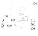
图1为本申请实施例提供的一种测距机构的结构示意图。FIG1 is a schematic diagram of the structure of a distance measuring mechanism provided in an embodiment of the present application.
图2为本申请实施例提供的一种测距机构的局部结构爆炸图。FIG. 2 is an exploded view of a local structure of a distance measuring mechanism provided in an embodiment of the present application.
图3为本申请实施例提供的一种测距机构装上靶标后的结构示意图。FIG3 is a schematic diagram of the structure of a distance measuring mechanism provided in an embodiment of the present application after being installed with a target.
图4为本申请实施例提供的一种测距机构拆除靶标后的结构示意图。FIG4 is a schematic diagram of the structure of a distance measuring mechanism after the target is removed provided in an embodiment of the present application.
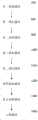
图5为本申请实施例提供的测距方法的一种流程图。FIG5 is a flow chart of a distance measurement method provided in an embodiment of the present application.
图6为本申请实施例提供的测距方法中步骤S8的计算公式所涉及的相关距离的标示图。FIG. 6 is a diagram illustrating the relevant distances involved in the calculation formula of step S8 in the distance measurement method provided in an embodiment of the present application.
图7为本申请实施例提供的测距装置的一种结构示意图。FIG. 7 is a schematic diagram of the structure of a distance measuring device provided in an embodiment of the present application.
图8为本申请实施例提供的电子设备的结构示意图。FIG8 is a schematic diagram of the structure of an electronic device provided in an embodiment of the present application.
标号说明:Description of labels:
100、喷头;200、基板;300、安装板;310、磁铁;400、第一激光位移传感器;500、靶标;510、把手;600、第二激光位移传感器;700、第一获取模块;800、第一调控模块;900、第二获取模块;1000、第三获取模块;1100、第二调控模块;1200、第四获取模块,1300、第五获取模块;1400、计算模块;1501、处理器;1502、存储器;1503、通信总线。100, nozzle; 200, substrate; 300, mounting plate; 310, magnet; 400, first laser displacement sensor; 500, target; 510, handle; 600, second laser displacement sensor; 700, first acquisition module; 800, first control module; 900, second acquisition module; 1000, third acquisition module; 1100, second control module; 1200, fourth acquisition module, 1300, fifth acquisition module; 1400, computing module; 1501, processor; 1502, memory; 1503, communication bus.
具体实施方式DETAILED DESCRIPTION
下面详细描述本发明的实施方式,所述实施方式的示例在附图中示出,其中自始至终相同或类似的标号表示相同或类似的元件或具有相同或类似功能的元件。下面通过参考附图描述的实施方式是示例性的,仅用于解释本发明,而不能理解为对本发明的限制。The embodiments of the present invention are described in detail below, examples of which are shown in the accompanying drawings, wherein the same or similar reference numerals throughout represent the same or similar elements or elements having the same or similar functions. The embodiments described below with reference to the accompanying drawings are exemplary and are only used to explain the present invention, and cannot be understood as limiting the present invention.
下面将结合本申请实施例中附图,对本申请实施例中的技术方案进行清楚、完整地描述,显然,所描述的实施例仅仅是本申请一部分实施例,而不是全部的实施例。通常在此处附图中描述和示出的本申请实施例的组件可以以各种不同的配置来布置和设计。因此,以下对在附图中提供的本申请的实施例的详细描述并非旨在限制要求保护的本申请的范围,而是仅仅表示本申请的选定实施例。基于本申请的实施例,本领域技术人员在没有做出创造性劳动的前提下所获得的所有其他实施例,都属于本申请保护的范围。The technical solutions in the embodiments of the present application will be clearly and completely described below in conjunction with the drawings in the embodiments of the present application. Obviously, the described embodiments are only a part of the embodiments of the present application, rather than all the embodiments. The components of the embodiments of the present application described and shown in the drawings here can be arranged and designed in various different configurations. Therefore, the following detailed description of the embodiments of the present application provided in the drawings is not intended to limit the scope of the application claimed for protection, but merely represents the selected embodiments of the present application. Based on the embodiments of the present application, all other embodiments obtained by those skilled in the art without making creative work belong to the scope of protection of the present application.
在本发明的描述中,需要理解的是,术语“中心”、“纵向”、“横向”、“长度”、“宽度”、“厚度”、“上”、“下”、“前”、“后”、“左”、“右”、“竖直”、“水平”、“顶”、“底”、“内”、“外”、“顺时针”、“逆时针”等指示的方位或位置关系为基于附图所示的方位或位置关系,仅是为了便于描述本发明和简化描述,而不是指示或暗示所指的装置或元件必须具有特定的方位、以特定的方位构造和操作,因此不能理解为对本发明的限制。此外,术语“第一”、“第二”仅用于描述目的,而不能理解为指示或暗示相对重要性或者隐含指明所指示的技术特征的数量。由此,限定有“第一”、“第二”的特征可以明示或者隐含地包括一个或者更多个所述特征。在本发明的描述中,“多个”的含义是两个或两个以上,除非另有明确具体的限定。In the description of the present invention, it should be understood that the terms "center", "longitudinal", "lateral", "length", "width", "thickness", "up", "down", "front", "back", "left", "right", "vertical", "horizontal", "top", "bottom", "inside", "outside", "clockwise", "counterclockwise" and the like indicate positions or positional relationships based on the positions or positional relationships shown in the accompanying drawings, and are only for the convenience of describing the present invention and simplifying the description, rather than indicating or implying that the device or element referred to must have a specific orientation, be constructed and operated in a specific orientation, and therefore cannot be understood as limiting the present invention. In addition, the terms "first" and "second" are only used for descriptive purposes, and cannot be understood as indicating or implying relative importance or implicitly indicating the number of technical features indicated. Therefore, the features defined as "first" and "second" may explicitly or implicitly include one or more of the features. In the description of the present invention, the meaning of "multiple" is two or more, unless otherwise clearly and specifically defined.
在本发明的描述中,需要说明的是,除非另有明确的规定和限定,术语“安装”、“相连”、“连接”应做广义理解,例如,可以是固定连接,也可以是可拆卸连接,或一体地连接;可以是机械连接,也可以是电连接或可以相互通讯;可以是直接相连,也可以通过中间媒介间接相连,可以是两个元件内部的连通或两个元件的相互作用关系。对于本领域的普通技术人员而言,可以根据具体情况理解上述术语在本发明中的具体含义。In the description of the present invention, it should be noted that, unless otherwise clearly specified and limited, the terms "installed", "connected", and "connected" should be understood in a broad sense, for example, it can be a fixed connection, a detachable connection, or an integral connection; it can be a mechanical connection, an electrical connection, or mutual communication; it can be a direct connection, or an indirect connection through an intermediate medium, it can be the internal connection of two elements or the interaction relationship between two elements. For ordinary technicians in this field, the specific meanings of the above terms in the present invention can be understood according to specific circumstances.
在本发明中,除非另有明确的规定和限定,第一特征在第二特征之“上”或之“下”可以包括第一和第二特征直接接触,也可以包括第一和第二特征不是直接接触而是通过它们之间的另外的特征接触。而且,第一特征在第二特征“之上”、“上方”和“上面”包括第一特征在第二特征正上方和斜上方,或仅仅表示第一特征水平高度高于第二特征。第一特征在第二特征“之下”、“下方”和“下面”包括第一特征在第二特征正下方和斜下方,或仅仅表示第一特征水平高度小于第二特征。In the present invention, unless otherwise clearly specified and limited, a first feature being "above" or "below" a second feature may include that the first and second features are in direct contact, or may include that the first and second features are not in direct contact but are in contact through another feature between them. Moreover, a first feature being "above", "above" and "above" a second feature includes that the first feature is directly above and obliquely above the second feature, or simply indicates that the first feature is higher in level than the second feature. A first feature being "below", "below" and "below" a second feature includes that the first feature is directly below and obliquely below the second feature, or simply indicates that the first feature is lower in level than the second feature.
下文的公开提供了许多不同的实施方式或例子用来实现本发明的不同结构。为了简化本发明的公开,下文中对特定例子的部件和设置进行描述。当然,它们仅仅为示例,并且目的不在于限制本发明。此外,本发明可以在不同例子中重复参考数字和/或参考字母,这种重复是为了简化和清楚的目的,其本身不指示所讨论各种实施方式和/或设置之间的关系。此外,本发明提供了的各种特定的工艺和材料的例子,但是本领域普通技术人员可以意识到其他工艺的应用和/或其他材料的使用。The disclosure below provides many different embodiments or examples to realize different structures of the present invention. In order to simplify the disclosure of the present invention, the parts and settings of specific examples are described below. Of course, they are only examples, and the purpose is not to limit the present invention. In addition, the present invention can repeat reference numbers and/or reference letters in different examples, and this repetition is for the purpose of simplicity and clarity, which itself does not indicate the relationship between the various embodiments and/or settings discussed. In addition, the present invention provides various specific examples of processes and materials, but those of ordinary skill in the art can be aware of the application of other processes and/or the use of other materials.
需要说明的是,下文所述的“上下方向”以附图1中的标注的箭头作为参考。It should be noted that the “up and down directions” described below refer to the arrows marked in FIG. 1 .
第一方面,参考附图1、附图2、附图3和附图4,本申请实施例提供一种测距机构,用于测量OLED喷墨打印机中喷头100与基板200之间的距离,包括:In a first aspect, referring to FIG. 1 , FIG. 2 , FIG. 3 , and FIG. 4 , an embodiment of the present application provides a distance measuring mechanism for measuring the distance between a
安装板300,安装板300与喷头100连接且能够与喷头100同步运动;A mounting
第一激光位移传感器400,第一激光位移传感器400固定设置在安装板300上,第一激光位移传感器400位于基板200的上方,且第一激光位移传感器400发出的激光光束竖直向下直射;A first
靶标500,靶标500安装在安装板300上且位于第一激光位移传感器400和基板200之间;靶标500能够阻断和开放第一激光位移传感器400发出的激光光束;A
第二激光位移传感器600,第二激光位移传感器600与承托基板200的平台连接且能够与平台同步运动;第二激光位移传感器600位于基板200的下方,且第二激光位移传感器600发出的激光光束竖直向上直射。The second
OLED喷墨打印机中,喷头100和承托基板200的平台一般都设置在滑轨上,例如喷头100设置在X轴滑轨上和Z轴滑轨上,使得喷头100能够沿X轴方向往复移动以及沿Z轴方向往复移动;承托基板200的平台设置在Y轴滑轨上,使得承托基板200的平台能够沿Y轴方向往复移动;从而使喷头100能够在基板200的表面进行喷墨打印。In an OLED inkjet printer, the platforms of the
喷头100和基板200之间的位置关系无疑会影响打印效果,喷头100与基板200之间的距离测算得越精准,则打印精度越高,打印效果就越好;而本实施例中,通过在喷头100和基板200之间加入靶标这一中间层,让上激光位移传感器和下激光位移传感器(上激光位移传感器即第一激光位移传感器400,下激光位移传感器即第二激光位移传感器600)测量的数据建立起联系,以致消除上激光位移传感器和下激光位移传感器的实际安装误差和激光位移传感器本身的检测精度误差的影响,经过简单的计算就能够获得喷头100和基板200之间的精确距离,从而大大提高了打印精度,进而提升打印效果。The positional relationship between the
在某些实施例中,参考附图3和附图4,靶标500以可拆卸的方式或可移动的方式安装在安装板300上。In some embodiments, referring to FIGS. 3 and 4 , the
在实际测距过程中,靶标500需要在阻断第一激光位移传感器400发出的激光光束和开放第一激光位移传感器400发出的激光光束这两个状态之间进行切换,将靶标500设计成可拆卸或可移动能够方便用户切换靶标500的状态,且结构简单,操作快捷。During the actual ranging process, the
具体的,可移动的方式可以为:在安装板300上设置滑轨,靶标500则滑动设置在滑轨上,从而实现靶标500的可移动,或在安装板300上设置推拉机构以推拉的方式实现靶标500的可移动;可拆卸的方式则可以为:螺钉连接、卡扣连接、嵌入连接等连接方式,但不仅限于此。Specifically, the movable method can be: a slide rail is set on the mounting
在某些优选的实施例中,参考附图2,安装板300固定设置有磁铁310,靶标500通过磁铁310吸附在安装板300上,磁吸连接结构简单操作方便,无需使用工具即可完成靶标500的装拆。In certain preferred embodiments, referring to FIG. 2 , the mounting
在某些实施例中,安装板300设置有至少一个定位孔,靶标500设置有至少一个定位销,每个定位销均套设有一个衬套且对应插接在一个定位孔中,通过定位销配合衬套插接在定位孔中实现靶标500与安装板300的固定连接,能够提高靶标500在安装板300上的固定力,在喷头100移动时一方面能够有效防止靶标500受力而意外掉落,大大提高稳定性;另一方面确保靶标500与安装板300的安装精度较高,能够避免靶标500出现微动而影响测算结果。In some embodiments, the mounting
在某些实施例中,参考附图1、附图2和附图3,靶标500设置有把手510。In certain embodiments, referring to FIGS. 1 , 2 , and 3 , the
设置把手510便于用户取放靶标500,避免人手与靶标500直接接触影响靶标500的精度。The
需要说明的是,靶标500采用电火花线切割加工工艺,保证了靶标500上下表面具有极高的加工精度。It should be noted that the
第二方面,请参照图5,图5是本申请实施例提供一种基于如上述实施例中的任一种测距机构的测距方法,包括步骤:In the second aspect, please refer to FIG. 5 , which is a distance measurement method based on any distance measurement mechanism in the above embodiments provided by the present application, including the steps of:
S1.获取靶标上下表面的第一距离;S1. Obtain the first distance between the upper and lower surfaces of the target;
S2.调控靶标的位置,以使靶标阻断第一激光位移传感器发出的激光光束;S2. regulating the position of the target so that the target blocks the laser beam emitted by the first laser displacement sensor;
S3.获取第一激光位移传感器到靶标上表面的第二距离;S3. Obtaining a second distance from the first laser displacement sensor to the upper surface of the target;
S4.获取第二激光位移传感器到靶标下表面的第三距离;S4. Obtaining a third distance from the second laser displacement sensor to the lower surface of the target;
S5.调控靶标的位置,以使靶标开放第一激光位移传感器发出的激光光束;S5. Regulating the position of the target so that the target opens the laser beam emitted by the first laser displacement sensor;
S6.获取第一激光位移传感器到基板上表面的第四距离;S6. Obtaining a fourth distance from the first laser displacement sensor to the upper surface of the substrate;
S7.获取第二激光位移传感器到喷头下表面的第五距离;S7. Obtaining the fifth distance from the second laser displacement sensor to the lower surface of the nozzle;
S8.根据第一距离、第二距离、第三距离、第四距离和第五距离,计算喷头下表面到基板上表面的第六距离。S8. Calculate a sixth distance from the lower surface of the nozzle to the upper surface of the substrate based on the first distance, the second distance, the third distance, the fourth distance and the fifth distance.
在实际测量过程中,靶标500上下表面的第一距离可以通过千分尺或激光测量获得;用户先将靶标500安装到安装板300上或通过移动靶标500使靶标500阻断第一激光位移传感器400发出的激光光束;第一激光位移传感器400发出的激光光束垂直射向到靶标500的上表面,经第一激光位移传感器400反馈获得第二距离;然后通过移动改变喷头100和基板200之间的相对位置,使得第二激光位移传感器600发出的激光光束垂直射向到靶标500的下表面,经第二激光位移传感器600反馈获得第三距离;然后拆卸靶标500或将靶标500移开,通过移动改变喷头100和基板200之间的相对位置,使得第一激光位移传感器400发出的激光光束垂直射向基板200的上表面,经第一激光位移传感器400反馈获得第四距离;然后通过移动改变喷头100和基板200之间的相对位置,使得第二激光位移传感器600发出的激光光束垂直射向到喷头100的下表面,经第二激光位移传感器600反馈获得第五距离;最后根据第一距离、第二距离、第三距离、第四距离和第五距离即可准确计算出第六距离,即喷头100的下表面到基板200的上表面之间的距离;过程简单,操作便捷,有效消除了上激光位移传感器和下激光位移传感器的实际安装误差和激光位移传感器本身的检测精度误差的影响,更精准地测算出喷头100与基板200之间的距离,使OLED喷墨打印机实现较好的打印效果。In the actual measurement process, the first distance between the upper and lower surfaces of the
需要说明的是,靶标500的上表面指的是朝向第一激光位移传感器400一侧且用于阻断第一激光位移传感器400发出的激光光束的表面;靶标500的下表面指的是背向靶标500的上表面的表面;靶标500的上下表面均为平直面。It should be noted that the upper surface of the
在某些实施例中,参考附图6(附图6目的在于清楚标示出所涉及的相关计算参数,并不代表各个结构的实际形状和实际位置,在实际应用时各个结构的实际形状和实际位置均可进行适应性调整),步骤S8中的具体步骤包括:In some embodiments, referring to FIG. 6 (FIG. 6 is intended to clearly indicate the relevant calculation parameters involved, and does not represent the actual shape and actual position of each structure. In actual application, the actual shape and actual position of each structure can be adaptively adjusted), the specific steps in step S8 include:
根据以下公式计算第六距离:The sixth distance is calculated according to the following formula:

其中,


计算过程中,


第三方面,请参照图7,图7是本申请实施例提供的一种基于如上述实施例中的任一种测距机构的测距装置,该测距装置以计算机程序的形式集成在该测距装置的后端控制设备中,该测距装置包括:In the third aspect, please refer to FIG. 7, which is a distance measuring device based on any distance measuring mechanism in the above embodiments provided by an embodiment of the present application. The distance measuring device is integrated in the back-end control device of the distance measuring device in the form of a computer program, and the distance measuring device includes:
第一获取模块700,用于获取靶标上下表面的第一距离;A
第一调控模块800,用于调控靶标的位置,以使靶标阻断第一激光位移传感器发出的激光光束;The
第二获取模块900,用于获取第一激光位移传感器到靶标上表面的第二距离;The
第三获取模块1000,用于获取第二激光位移传感器到靶标下表面的第三距离;A
第二调控模块1100,用于调控靶标的位置,以使靶标开放第一激光位移传感器发出的激光光束;The
第四获取模块1200,用于获取第一激光位移传感器到基板上表面的第四距离;A
第五获取模块1300,用于获取第二激光位移传感器到喷头下表面的第五距离;A
计算模块1400,用于根据第一距离、第二距离、第三距离、第四距离和第五距离,计算喷头下表面到基板上表面的第六距离。The
在某些实施例中,在计算模块1400用于根据第一距离、第二距离、第三距离、第四距离和第五距离,计算喷头下表面到基板上表面的第六距离的时候执行:In some embodiments, when the
根据以下公式计算第六距离:The sixth distance is calculated according to the following formula:

其中,


第四方面,请参照图8,图8为本申请实施例提供的一种电子设备的结构示意图,本申请提供一种电子设备,包括:处理器1501和存储器1502,处理器1501和存储器1502通过通信总线1503和/或其他形式的连接机构(未标出)互连并相互通讯,存储器1502存储有处理器1501可执行的计算机可读取指令,当电子设备运行时,处理器1501执行该计算机可读取指令,以执行上述第二方面的实施例的任一可选的实现方式中的测距方法,以实现以下功能:获取靶标上下表面的第一距离;调控靶标的位置,以使靶标阻断第一激光位移传感器发出的激光光束;获取第一激光位移传感器到靶标上表面的第二距离;获取第二激光位移传感器到靶标下表面的第三距离;调控靶标的位置,以使靶标开放第一激光位移传感器发出的激光光束;获取第一激光位移传感器到基板上表面的第四距离;获取第二激光位移传感器到喷头下表面的第五距离;根据第一距离、第二距离、第三距离、第四距离和第五距离,计算喷头下表面到基板上表面的第六距离。In the fourth aspect, please refer to FIG. 8, which is a schematic diagram of the structure of an electronic device provided in an embodiment of the present application. The present application provides an electronic device, including: a
第五方面,本申请实施例提供一种存储介质,其上存储有计算机程序,计算机程序被处理器执行时,执行上述第二方面的实施例的任一可选的实现方式中的测距方法,以实现以下功能:获取靶标上下表面的第一距离;调控靶标的位置,以使靶标阻断第一激光位移传感器发出的激光光束;获取第一激光位移传感器到靶标上表面的第二距离;获取第二激光位移传感器到靶标下表面的第三距离;调控靶标的位置,以使靶标开放第一激光位移传感器发出的激光光束;获取第一激光位移传感器到基板上表面的第四距离;获取第二激光位移传感器到喷头下表面的第五距离;根据第一距离、第二距离、第三距离、第四距离和第五距离,计算喷头下表面到基板上表面的第六距离。In a fifth aspect, an embodiment of the present application provides a storage medium having a computer program stored thereon. When the computer program is executed by a processor, the ranging method in any optional implementation of the embodiment of the second aspect is executed to achieve the following functions: obtaining a first distance between the upper and lower surfaces of the target; adjusting the position of the target so that the target blocks the laser beam emitted by the first laser displacement sensor; obtaining a second distance from the first laser displacement sensor to the upper surface of the target; obtaining a third distance from the second laser displacement sensor to the lower surface of the target; adjusting the position of the target so that the target opens the laser beam emitted by the first laser displacement sensor; obtaining a fourth distance from the first laser displacement sensor to the upper surface of the substrate; obtaining a fifth distance from the second laser displacement sensor to the lower surface of the nozzle; and calculating a sixth distance from the lower surface of the nozzle to the upper surface of the substrate based on the first distance, the second distance, the third distance, the fourth distance and the fifth distance.
其中,存储介质可以由任何类型的易失性或非易失性存储设备或者它们的组合实现,如静态随机存取存储器(Static Random Access Memory, 简称SRAM),电可擦除可编程只读存储器(Electrically Erasable Programmable Read-Only Memory, 简称EEPROM),可擦除可编程只读存储器(Erasable Programmable Read Only Memory, 简称EPROM),可编程只读存储器(Programmable Red-Only Memory, 简称PROM),只读存储器(Read-Only Memory, 简称ROM),磁存储器,快闪存储器,磁盘或光盘。Among them, the storage medium can be implemented by any type of volatile or non-volatile storage device or a combination thereof, such as static random access memory (SRAM), electrically erasable programmable read-only memory (EEPROM), erasable programmable read-only memory (EPROM), programmable red-only memory (PROM), read-only memory (ROM), magnetic storage, flash memory, magnetic disk or optical disk.
在本申请所提供的实施例中,应该理解到,所揭露装置和方法,可以通过其它的方式实现。以上所描述的装置实施例仅仅是示意性的,例如,所述单元的划分,仅仅为一种逻辑功能划分,实际实现时可以有另外的划分方式,又例如,多个单元或组件可以结合或者可以集成到另一个系统,或一些特征可以忽略,或不执行。另一点,所显示或讨论的相互之间的耦合或直接耦合或通信连接可以是通过一些通信接口,装置或单元的间接耦合或通信连接,可以是电性,机械或其它的形式。In the embodiments provided in the present application, it should be understood that the disclosed devices and methods can be implemented in other ways. The device embodiments described above are merely schematic. For example, the division of the units is only a logical function division. There may be other division methods in actual implementation. For example, multiple units or components can be combined or integrated into another system, or some features can be ignored or not executed. Another point is that the mutual coupling or direct coupling or communication connection shown or discussed can be through some communication interfaces, indirect coupling or communication connection of devices or units, which can be electrical, mechanical or other forms.
另外,作为分离部件说明的单元可以是或者也可以不是物理上分开的,作为单元显示的部件可以是或者也可以不是物理单元,即可以位于一个地方,或者也可以分布到多个网络单元上。可以根据实际的需要选择其中的部分或者全部单元来实现本实施例方案的目的。In addition, the units described as separate components may or may not be physically separated, and the components shown as units may or may not be physical units, that is, they may be located in one place or distributed on multiple network units. Some or all of the units may be selected according to actual needs to achieve the purpose of the solution of this embodiment.
再者,在本申请各个实施例中的各功能模块可以集成在一起形成一个独立的部分,也可以是各个模块单独存在,也可以两个或两个以上模块集成形成一个独立的部分。Furthermore, the functional modules in the various embodiments of the present application may be integrated together to form an independent part, or each module may exist separately, or two or more modules may be integrated to form an independent part.
在本文中,诸如第一和第二等之类的关系术语仅仅用来将一个实体或者操作与另一个实体或操作区分开来,而不一定要求或者暗示这些实体或操作之间存在任何这种实际的关系或者顺序。In this document, relational terms such as first and second, etc. are used merely to distinguish one entity or operation from another entity or operation, but do not necessarily require or imply any such actual relationship or order between these entities or operations.
以上所述仅为本申请的实施例而已,并不用于限制本申请的保护范围,对于本领域的技术人员来说,本申请可以有各种更改和变化。凡在本申请的精神和原则之内,所作的任何修改、等同替换、改进等,均应包含在本申请的保护范围之内。The above description is only an embodiment of the present application and is not intended to limit the scope of protection of the present application. For those skilled in the art, the present application may have various modifications and variations. Any modification, equivalent replacement, improvement, etc. made within the spirit and principle of the present application shall be included in the scope of protection of the present application.
Claims (10)
Translated fromChinese


Priority Applications (1)
| Application Number | Priority Date | Filing Date | Title |
|---|---|---|---|
| CN202310185565.0ACN115854888B (en) | 2023-03-01 | 2023-03-01 | Distance measuring mechanism, distance measuring method and related equipment |
Applications Claiming Priority (1)
| Application Number | Priority Date | Filing Date | Title |
|---|---|---|---|
| CN202310185565.0ACN115854888B (en) | 2023-03-01 | 2023-03-01 | Distance measuring mechanism, distance measuring method and related equipment |
Publications (2)
| Publication Number | Publication Date |
|---|---|
| CN115854888A CN115854888A (en) | 2023-03-28 |
| CN115854888Btrue CN115854888B (en) | 2023-05-05 |
Family
ID=85659517
Family Applications (1)
| Application Number | Title | Priority Date | Filing Date |
|---|---|---|---|
| CN202310185565.0AActiveCN115854888B (en) | 2023-03-01 | 2023-03-01 | Distance measuring mechanism, distance measuring method and related equipment |
Country Status (1)
| Country | Link |
|---|---|
| CN (1) | CN115854888B (en) |
Families Citing this family (2)
| Publication number | Priority date | Publication date | Assignee | Title |
|---|---|---|---|---|
| CN116900519A (en)* | 2023-07-28 | 2023-10-20 | 山东奥太电气有限公司 | A laser processing safety protection method and system |
| CN118617878B (en)* | 2024-08-14 | 2024-10-22 | 季华实验室 | An OLED inkjet printing head module capable of real-time monitoring of accuracy and a monitoring method thereof |
Citations (7)
| Publication number | Priority date | Publication date | Assignee | Title |
|---|---|---|---|---|
| JP2012163419A (en)* | 2011-02-04 | 2012-08-30 | Toshiba Corp | Thickness measuring instrument |
| CN108363066A (en)* | 2018-01-15 | 2018-08-03 | 成都大亦科技有限公司 | A kind of high-precision distance measurement method |
| CN110044312A (en)* | 2019-05-16 | 2019-07-23 | 江苏塔菲尔新能源科技股份有限公司 | A kind of measuring device and its measurement method of thickness |
| CN111791589A (en)* | 2020-09-10 | 2020-10-20 | 季华实验室 | Inkjet printer-based positioning detection method, device, electronic device and medium |
| CN112123948A (en)* | 2020-09-28 | 2020-12-25 | 深圳市华星光电半导体显示技术有限公司 | Printing head module and ink-jet printing method |
| CN113959340A (en)* | 2021-09-23 | 2022-01-21 | 中大(海南)智能科技有限公司 | Laser ranging system, method, device and storage medium |
| CN115655114A (en)* | 2022-11-15 | 2023-01-31 | 海克斯康制造智能技术(青岛)有限公司 | Compensation method and compensation device based on large-length calibration device |
Family Cites Families (5)
| Publication number | Priority date | Publication date | Assignee | Title |
|---|---|---|---|---|
| CN107531041B (en)* | 2015-05-08 | 2019-09-27 | 惠普深蓝有限责任公司 | Correction of measured sensor distance |
| CN107883887B (en)* | 2016-09-30 | 2019-11-26 | 上海微电子装备(集团)股份有限公司 | A kind of optical measuring device and method |
| US10876830B2 (en)* | 2019-03-11 | 2020-12-29 | Honeywell International Inc. | Non-contact sheet material thickness measurement system |
| JP7518678B2 (en)* | 2020-07-06 | 2024-07-18 | キヤノン株式会社 | Inkjet recording apparatus and control method thereof |
| US20220227057A1 (en)* | 2021-01-19 | 2022-07-21 | Markforged, Inc | Z-scale and misalignment calibration for 3d printing |
- 2023
- 2023-03-01CNCN202310185565.0Apatent/CN115854888B/enactiveActive
Patent Citations (7)
| Publication number | Priority date | Publication date | Assignee | Title |
|---|---|---|---|---|
| JP2012163419A (en)* | 2011-02-04 | 2012-08-30 | Toshiba Corp | Thickness measuring instrument |
| CN108363066A (en)* | 2018-01-15 | 2018-08-03 | 成都大亦科技有限公司 | A kind of high-precision distance measurement method |
| CN110044312A (en)* | 2019-05-16 | 2019-07-23 | 江苏塔菲尔新能源科技股份有限公司 | A kind of measuring device and its measurement method of thickness |
| CN111791589A (en)* | 2020-09-10 | 2020-10-20 | 季华实验室 | Inkjet printer-based positioning detection method, device, electronic device and medium |
| CN112123948A (en)* | 2020-09-28 | 2020-12-25 | 深圳市华星光电半导体显示技术有限公司 | Printing head module and ink-jet printing method |
| CN113959340A (en)* | 2021-09-23 | 2022-01-21 | 中大(海南)智能科技有限公司 | Laser ranging system, method, device and storage medium |
| CN115655114A (en)* | 2022-11-15 | 2023-01-31 | 海克斯康制造智能技术(青岛)有限公司 | Compensation method and compensation device based on large-length calibration device |
Non-Patent Citations (1)
| Title |
|---|
| 杨霄等.基于激光测距的火车车轴轮座直径非接触式测量方法研究.《机电工程技术》.2018,第47卷(第3期),第17-21页.* |
Also Published As
| Publication number | Publication date |
|---|---|
| CN115854888A (en) | 2023-03-28 |
Similar Documents
| Publication | Publication Date | Title |
|---|---|---|
| CN115854888B (en) | Distance measuring mechanism, distance measuring method and related equipment | |
| US11498263B2 (en) | Calibration and alignment of 3D printing deposition heads | |
| CN110253877B (en) | 3D printing device and control method thereof | |
| CN203876238U (en) | Single-nozzle working structure for a double-nozzle 3D printer | |
| CN103660300A (en) | Automatic-leveling 3D printer and printing method thereof | |
| BR112013005307B1 (en) | APPLIANCE FOR ALIGNING A PRINTER HAVING AN INK JET HEADS ARRANGEMENT | |
| JP6723332B2 (en) | Nanoimprint Lithography with 6-DOF Imprint Head Module | |
| US20120156320A1 (en) | Manufacturing-process equipment | |
| CN111033386B (en) | Exposure System Alignment and Calibration Method | |
| CN109442170A (en) | A kind of CCD regulating mechanism | |
| KR101184424B1 (en) | Goniostage | |
| CN105183037A (en) | Laser direct-write lithography machine precise temperature control method | |
| KR102717090B1 (en) | Model-based dynamic position compensation for digital lithography tools | |
| CN203650991U (en) | Automatic leveling 3D printer | |
| CN107883866B (en) | A kind of optical measuring device and method | |
| CN107024185B (en) | Method and device for measuring basal surface | |
| CN101261455B (en) | Device and method for photo-etching machine focusing system performance evaluation | |
| EP3413017A1 (en) | Laser level ruler | |
| CN115309196B (en) | Turntable control method, device, equipment and storage medium | |
| CN115437102A (en) | Two-degree-of-freedom adjusting device of long plane reflector | |
| JP4521982B2 (en) | Electronic device mounting apparatus and feeder bank | |
| CN102310640A (en) | Adjusting device | |
| CN119217722B (en) | Position positioning method and system of spray head dock and 3D printing equipment | |
| US12443116B2 (en) | Machine measurement metrology frame for a lithography system | |
| CN118102606A (en) | An electric fluid nozzle adjustment device |
Legal Events
| Date | Code | Title | Description |
|---|---|---|---|
| PB01 | Publication | ||
| PB01 | Publication | ||
| SE01 | Entry into force of request for substantive examination | ||
| SE01 | Entry into force of request for substantive examination | ||
| GR01 | Patent grant | ||
| GR01 | Patent grant |