CN115846319A - A new type of portable pipeline cleaning robot - Google Patents
A new type of portable pipeline cleaning robotDownload PDFInfo
- Publication number
- CN115846319A CN115846319ACN202211497486.5ACN202211497486ACN115846319ACN 115846319 ACN115846319 ACN 115846319ACN 202211497486 ACN202211497486 ACN 202211497486ACN 115846319 ACN115846319 ACN 115846319A
- Authority
- CN
- China
- Prior art keywords
- correspondingly
- cleaning robot
- double
- friction wheel
- shaft motor
- Prior art date
- Legal status (The legal status is an assumption and is not a legal conclusion. Google has not performed a legal analysis and makes no representation as to the accuracy of the status listed.)
- Pending
Links
- 238000004140cleaningMethods0.000titleclaimsabstractdescription37
- 230000007246mechanismEffects0.000claimsabstractdescription71
- 239000007921spraySubstances0.000claimsdescription16
- 238000009434installationMethods0.000claimsdescription13
- 230000005540biological transmissionEffects0.000claimsdescription12
- 239000007788liquidSubstances0.000claimsdescription10
- 238000005507sprayingMethods0.000claimsdescription7
- 230000007613environmental effectEffects0.000abstractdescription4
- 239000010865sewageSubstances0.000abstractdescription4
- 238000013461designMethods0.000description4
- 230000000694effectsEffects0.000description2
- 238000005286illuminationMethods0.000description2
- 238000012986modificationMethods0.000description2
- 230000004048modificationEffects0.000description2
- XLYOFNOQVPJJNP-UHFFFAOYSA-NwaterSubstancesOXLYOFNOQVPJJNP-UHFFFAOYSA-N0.000description2
- 230000009286beneficial effectEffects0.000description1
- 230000003139buffering effectEffects0.000description1
- 238000011161developmentMethods0.000description1
- 238000010586diagramMethods0.000description1
- 230000005611electricityEffects0.000description1
- 239000012530fluidSubstances0.000description1
- 230000010354integrationEffects0.000description1
- 230000007774longtermEffects0.000description1
- 238000012423maintenanceMethods0.000description1
- 238000004519manufacturing processMethods0.000description1
- 238000000034methodMethods0.000description1
- 238000007789sealingMethods0.000description1
- 238000004659sterilization and disinfectionMethods0.000description1
- 238000006467substitution reactionMethods0.000description1
Images


Landscapes
- Cleaning In General (AREA)
Abstract
Translated fromChinese
Description
Translated fromChinese技术领域technical field
本发明涉及管道疏通技术领域,主要涉及一种新型便携式管道清洗机器人。The invention relates to the technical field of pipeline dredging, and mainly relates to a novel portable pipeline cleaning robot.
背景技术Background technique
管道机器人是一种可沿细小管道内部或外部自动行走、携带一种或多种传感器及操作机械,在工作人员的遥控操作或计算机自动控制下,进行一系列管道作业的机、电、仪一体化系统。随着人类社会的高速发展,大型餐厨食堂及城市污水处理管道的布控使用体现格外具体。Pipeline robot is a kind of machine, electricity and instrument that can walk automatically along the inside or outside of a small pipeline, carry one or more sensors and operating machinery, and perform a series of pipeline operations under the remote control of the staff or the automatic control of the computer. system. With the rapid development of human society, the deployment and control of large kitchens and canteens and urban sewage treatment pipelines are particularly specific.
在如今日常生产生活过程中,管道的使用表现在方方面面。由于地下管道的开放性及长期使用,残渣油污及各类残余物会通过入口进入管道中,久而久之便会堵塞管道,影响其使用。考虑到管道设计以及环境安全等一系列问题,若以人工清洁的方式去处理,作业难度高,在复杂情况下安全性缺乏相应保障,劳动力成本高昂,风险及成本会大幅提升;同时由于其地下特殊的作业环境,对操作人员要求极高,从业人员也较少。因此,有必要提出一种可以代替人工的便携式清理设备,以便对管道内部进行疏通清理。In today's daily production and life, the use of pipelines is manifested in all aspects. Due to the openness and long-term use of underground pipelines, residual oil and various residues will enter the pipeline through the entrance, which will block the pipeline over time and affect its use. Considering a series of problems such as pipeline design and environmental safety, if it is handled by manual cleaning, the operation will be difficult, and the safety will not be guaranteed in complex situations, the labor cost will be high, and the risk and cost will be greatly increased; The special working environment has extremely high requirements on operators, and there are fewer employees. Therefore, it is necessary to propose a portable cleaning device that can replace manual work, so that the inside of the pipeline can be dredged and cleaned.
关于管道疏通的相关专利已有公开。如中国专利申请号为CN202020196294.0的申请案公开了一种管道清理疏通装置,包括驱动机构,所述驱动机构包括输送管、电机底座、电机、主动带轮、传动带,所述输送管顶部设有所述电机底座,所述电机底座顶部设有所述电机,所述电机输出轴上设有所述主动带轮,所述主动带轮下方设有从动带轮,所述从动带轮和所述主动带轮外侧设有所述传动带,所述输送管底部靠近一侧设有出料管,所述驱动机构上设有疏通机构和移动机构,所述疏通机构包括转轴、送料桨、破碎刀、钻头,所述从动带轮上通过键连接有所述转轴,所述转轴外侧焊接有所述送料桨。该申请案虽然能够进行管道清理疏通,但由于其整体结构外形的原因,在管道内移动前进时较为不便,同时也无法较好地将管道内部堵塞的杂物带出来,清理效果有限,使用灵活性较差,其整体结构有待进一步改进。Related patents about pipeline dredging have been published. For example, the Chinese patent application number CN202020196294.0 discloses a pipeline cleaning and dredging device, which includes a driving mechanism. The driving mechanism includes a delivery pipe, a motor base, a motor, a driving pulley, and a transmission belt. There is the motor base, the motor is arranged on the top of the motor base, the driving pulley is arranged on the output shaft of the motor, the driven pulley is arranged under the driving pulley, and the driven pulley The transmission belt is provided on the outside of the driving pulley, the bottom of the delivery pipe is provided with a discharge pipe near one side, and the driving mechanism is provided with a dredging mechanism and a moving mechanism, and the dredging mechanism includes a rotating shaft, a feeding paddle, A crushing knife and a drill bit, the driven pulley is connected with the rotating shaft through a key, and the feeding paddle is welded on the outside of the rotating shaft. Although this application can clean and dredge the pipeline, due to its overall structural shape, it is inconvenient to move forward in the pipeline, and at the same time it cannot bring out the debris blocked inside the pipeline, the cleaning effect is limited, and it is flexible to use The performance is poor, and its overall structure needs to be further improved.
发明内容Contents of the invention
本发明提供一种新型便携式管道清洗机器人,能够在管道内顺利前进,将管道内的杂物顶出来,实现管道疏通,有效解决了餐厨等下水排污管道环境清理问题,其体积小,携带方便,相较于人工清理而言成本低,安全性更高。The invention provides a new type of portable pipeline cleaning robot, which can advance smoothly in the pipeline, push out the sundries in the pipeline, realize the dredging of the pipeline, and effectively solve the environmental cleaning problem of the sewer and sewage pipelines such as restaurants and kitchens. It is small in size and easy to carry , compared with manual cleaning, the cost is lower and the safety is higher.
为了实现上述目的,本发明采用以下技术方案 :一种新型便携式管道清洗机器人,包括中心体、转动装置和前进装置,所述转动装置和前进装置分别对应安装于中心体两侧;所述转动装置包括第一安装盘和设置于第一安装盘四周的多个第一摩擦轮旋转机构,用于贴着管道内侧壁周向转动;所述前进装置包括第二安装盘和设置于第二安装盘四周的多个第二摩擦轮旋转机构,用于贴着管道内侧壁沿轴线方向前进移动。In order to achieve the above object, the present invention adopts the following technical solutions: a new type of portable pipeline cleaning robot, including a central body, a rotating device and an advancing device, the rotating device and the advancing device are respectively installed on both sides of the central body; the rotating device It includes a first mounting plate and a plurality of first friction wheel rotating mechanisms arranged around the first mounting plate, which are used for circumferential rotation against the inner wall of the pipeline; the advancing device includes a second mounting plate and a A plurality of second friction wheel rotating mechanisms around are used to advance and move along the axial direction against the inner wall of the pipeline.
优选的,所述第一摩擦轮旋转机构包括第一连接杆、第一双轴电机和第一橡胶摩擦轮,所述第一安装盘的四周均匀设有多个安装孔,所述第一连接杆对应安装于安装孔内,所述第一连接杆的外侧端部对应安装有第一双轴电机,所述第一双轴电机顶部与底部的输出轴上均对应安装有第一橡胶摩擦轮,多个第一橡胶摩擦轮呈环形对应分布。Preferably, the first friction wheel rotation mechanism includes a first connecting rod, a first biaxial motor and a first rubber friction wheel, a plurality of mounting holes are uniformly arranged around the first mounting plate, and the first connecting The rod is correspondingly installed in the mounting hole, the outer end of the first connecting rod is correspondingly installed with a first biaxial motor, and the output shafts of the top and bottom of the first biaxial motor are respectively equipped with a first rubber friction wheel , a plurality of first rubber friction wheels are correspondingly distributed in a ring shape.
优选的,所述第一连接杆采用可伸缩结构,其伸缩端对应安装有第一双轴电机;所述第一双轴电机与其对应的安装孔之间对应设有缓冲机构。Preferably, the first connecting rod adopts a telescopic structure, the telescopic end of which is correspondingly installed with a first biaxial motor; a buffer mechanism is correspondingly provided between the first biaxial motor and its corresponding mounting hole.
优选的,所述第一安装盘的外侧端面中部对应设有识别机构,该识别机构的四周对应设有照明机构。Preferably, the middle part of the outer end surface of the first mounting plate is correspondingly provided with an identification mechanism, and the periphery of the identification mechanism is correspondingly provided with an illumination mechanism.
优选的,所述第二摩擦轮旋转机构包括第二连接杆、第二双轴电机和第二橡胶摩擦轮,所述第二安装盘的四周均匀设有多个第二连接杆,该第二连接杆的一端对应安装于第二安装盘侧部,其另一端对应安装有第二双轴电机;所述第二双轴电机左右两侧的输出轴上均通过传动机构对应安装有第二橡胶摩擦轮,多个第二橡胶摩擦轮呈环形对应分布。Preferably, the second friction wheel rotation mechanism includes a second connecting rod, a second biaxial motor and a second rubber friction wheel, and a plurality of second connecting rods are uniformly arranged around the second mounting plate, and the second One end of the connecting rod is correspondingly installed on the side of the second installation plate, and the other end is correspondingly installed with a second double-axis motor; the output shafts on the left and right sides of the second double-axis motor are correspondingly installed with a second rubber through the transmission mechanism. As for the friction wheel, a plurality of second rubber friction wheels are correspondingly distributed in a ring shape.
优选的,所述传动机构为锥齿轮传动机构,包括两个锥齿轮,其中一个锥齿轮对应安装于第二双轴电机的输出轴上,另一个锥齿轮对应安装于安装轴一端,两个锥齿轮相啮合,且两个锥齿轮两轴之间的交角小于90°,所述第二橡胶摩擦轮对应安装于安装轴另一端。Preferably, the transmission mechanism is a bevel gear transmission mechanism, including two bevel gears, one of which is correspondingly installed on the output shaft of the second biaxial motor, and the other is correspondingly installed on one end of the installation shaft, and the two bevel gears are The gears are meshed, and the intersection angle between the two shafts of the two bevel gears is less than 90°, and the second rubber friction wheel is correspondingly installed on the other end of the installation shaft.
优选的,所述第二连接杆采用可伸缩结构,其伸缩端对应安装有第二双轴电机。Preferably, the second connecting rod adopts a telescopic structure, and a second biaxial motor is correspondingly installed at the telescopic end.
优选的,所述第二双轴电机的外侧端面中部对应设有喷淋孔,所述第二安装盘内对应装有高压喷洗液,所述喷淋孔均与第二安装盘内的高压喷洗液相连通,以便向管道内壁喷出清洗液。Preferably, the middle part of the outer end face of the second double-axis motor is correspondingly provided with a spray hole, and the high-pressure spray liquid is correspondingly installed in the second mounting plate, and the spray holes are connected with the high-pressure spraying liquid in the second mounting plate. The spraying liquid is connected so as to spray the cleaning liquid to the inner wall of the pipeline.
优选的,所述第一安装盘四周对应设有三个周向均匀分布的第一摩擦轮旋转机构,所述前进装置四周对应设有三个周向均匀分布的第二摩擦轮旋转机构。Preferably, three first friction wheel rotation mechanisms evenly distributed in the circumferential direction are correspondingly provided around the first mounting plate, and three second friction wheel rotation mechanisms evenly distributed in the circumferential direction are correspondingly provided around the advancing device.
优选的,所述中心体内部还对应设有电源和核心控制机构,所述电源可用于给转动装置以及前进装置供电,所述核心控制机构可用于控制转动装置以及前进装置工作。Preferably, a power supply and a core control mechanism are correspondingly provided inside the central body, the power supply can be used to supply power to the rotating device and the advancing device, and the core control mechanism can be used to control the operation of the rotating device and the advancing device.
与现有技术相比,本发明的有益效果是:Compared with prior art, the beneficial effect of the present invention is:
本发明通过在中心体的两侧分别对应设置转动装置和前进装置,并对转动装置和前进装置的具体结构进行优化设计,使用时,将该机器人对应放入待清理的管道内,将转动装置作为前部,前进装置作为后部,利用转动装置中的第一橡胶摩擦轮贴着管道内侧壁周向转动,同时利用前进装置中的第二橡胶摩擦轮贴着管道内侧壁沿轴线方向前进移动,从而使得该机器人在管道内顺利前进,通过转动装置将管道内的杂物顶出来,实现管道疏通,有效解决了多种油污下水管道下清理疏通工作,其体积小,携带方便,相较于人工清理而言成本低,安全性更高。In the present invention, a rotating device and an advancing device are correspondingly arranged on both sides of the central body, and the specific structures of the rotating device and the advancing device are optimized. When in use, the robot is correspondingly put into the pipeline to be cleaned, and the rotating device As the front part, the advancing device is used as the rear part, using the first rubber friction wheel in the rotating device to rotate circumferentially against the inner wall of the pipe, and at the same time using the second rubber friction wheel in the advancing device to move forward along the axial direction against the inner wall of the pipe , so that the robot advances smoothly in the pipeline, and the sundries in the pipeline are ejected through the rotating device to realize the dredging of the pipeline, which effectively solves the cleaning and dredging work of various oily sewage pipelines. It is small in size and easy to carry. Compared with The cost of manual cleaning is low and the safety is higher.
附图说明Description of drawings
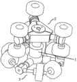
图1是本发明的管道清洗机器人组装好时的结构示意图;Fig. 1 is a structural schematic view of the pipe cleaning robot of the present invention when it is assembled;
图2是本发明的管道清洗机器人未组装时的结构示意图;Fig. 2 is a schematic structural view of the pipe cleaning robot of the present invention when it is not assembled;
图3是本发明的转动装置的结构示意图;Fig. 3 is the structural representation of rotating device of the present invention;
图4是本发明的前进装置的结构示意图。Fig. 4 is a structural schematic diagram of the advancing device of the present invention.
图中:1、中心体;2、转动装置;21、第一安装盘;211、安装孔;22、照明机构;23、识别机构;24、第一连接杆;25、第一双轴电机;26、第一橡胶摩擦轮;3、前进装置;31、第二安装盘;32、第二连接杆;33、第二双轴电机;34、安装轴;35、第二橡胶摩擦轮。In the figure: 1. Central body; 2. Rotating device; 21. First mounting plate; 211. Mounting hole; 22. Lighting mechanism; 23. Identification mechanism; 24. First connecting rod; 25. First biaxial motor; 26, the first rubber friction wheel; 3, the advancing device; 31, the second installation plate; 32, the second connecting rod; 33, the second biaxial motor; 34, the installation shaft; 35, the second rubber friction wheel.
具体实施方式Detailed ways
下面将结合本发明实施例中的附图,对本发明实施例中的技术方案进行清楚、完整地描述,显然,所描述的实施例仅仅是本发明一部分实施例,而不是全部的实施例。基于本发明中的实施例,本领域普通技术人员在没有做出创造性劳动前提下所获得的所有其他实施例,都属于本发明保护的范围。The following will clearly and completely describe the technical solutions in the embodiments of the present invention with reference to the accompanying drawings in the embodiments of the present invention. Obviously, the described embodiments are only some, not all, embodiments of the present invention. Based on the embodiments of the present invention, all other embodiments obtained by persons of ordinary skill in the art without making creative efforts belong to the protection scope of the present invention.
实施例Example
请参阅图1-4,本实施例的一种新型便携式管道清洗机器人,包括中心体1、转动装置2和前进装置3,所述转动装置2和前进装置3分别对应安装于中心体1两侧。所述转动装置2包括第一安装盘21和设置于第一安装盘21四周的多个第一摩擦轮旋转机构,用于贴着管道内侧壁周向转动。所述前进装置3包括第二安装盘31和设置于第二安装盘31四周的多个第二摩擦轮旋转机构,用于贴着管道内侧壁沿轴线方向前进移动。Please refer to Figures 1-4, a new type of portable pipeline cleaning robot in this embodiment includes a
具体的,所述第一摩擦轮旋转机构包括第一连接杆24、第一双轴电机25和第一橡胶摩擦轮26,所述第一安装盘21的四周均匀设有多个安装孔211,所述第一连接杆24对应安装于安装孔211内,所述第一连接杆25的外侧端部对应安装有第一双轴电机26。所述第一双轴电机26顶部与底部的输出轴上均对应安装有第一橡胶摩擦轮27,多个第一橡胶摩擦轮27呈环形对应分布。同时开启第一双轴电机26,使得多个第一橡胶摩擦轮27旋转,通过多个第一橡胶摩擦轮27贴着管道内侧壁从而进行周向转动。所述第一连接杆25采用可伸缩结构,该可伸缩结构具体可采用电动伸缩杆或气缸等现有伸缩设备,其伸缩端对应安装有第一双轴电机26,通过采用可伸缩的第一连接杆25,以便该机器人能够适用于不同管径的管道,提高其普遍适用性。所述第一双轴电机26与其对应的安装孔211之间对应设有缓冲机构,该缓冲机构可直接采用缓冲弹簧或其他现有缓冲结构,通过设置缓冲机构,从而在第一橡胶摩擦轮27贴着管道内侧壁周向转动时起到缓冲作用。Specifically, the first friction wheel rotation mechanism includes a first connecting
所述第一安装盘21的外侧端面中部对应设有识别机构23,该识别机构23的四周对应设有照明机构22。所述照明机构22具体可采用LED灯,所述识别机构23具体可采用微孔摄像机或多目相机,通过设置照明机构22以及识别机构23,以便用于获知管道内部情况。An
所述第二摩擦轮旋转机构包括第二连接杆32、第二双轴电机33和第二橡胶摩擦轮35,所述第二安装盘31的四周均匀设有多个第二连接杆32,该第二连接杆32的一端对应安装于第二安装盘31侧部,其另一端对应安装有第二双轴电机33。所述第二双轴电机33左右两侧的输出轴上均通过传动机构对应安装有第二橡胶摩擦轮35,多个第二橡胶摩擦轮35呈环形对应分布。所述传动机构具体为锥齿轮传动机构,采用齿轮连接设计以保障产品运动的连贯性。所述锥齿轮传动机构包括两个锥齿轮,其中一个锥齿轮对应安装于第二双轴电机33的输出轴上,另一个锥齿轮对应安装于安装轴34一端,两个锥齿轮相啮合,所述第二橡胶摩擦轮35对应安装于安装轴34另一端。所述两个锥齿轮两轴之间的交角小于90°,具体可设置为15°-60°,优选为30°,以便第二橡胶摩擦轮35能够较好地贴合着管道内侧壁。同时开启第二双轴电机33,使得多个第二橡胶摩擦轮35旋转,通过多个第二橡胶摩擦轮35贴着管道内侧壁沿轴线方向前进移动,从而使得该机器人前进。所述第二连接杆32采用可伸缩结构,该可伸缩结构具体可采用电动伸缩杆或气缸等现有伸缩设备,其伸缩端对应安装有第二双轴电机33,通过采用可伸缩的第二连接杆32,以便其第二橡胶摩擦轮35能够有效贴合着不同管径的管道内侧壁,使得该机器人可适用于各种管道,提高其普遍适用性。The second friction wheel rotation mechanism includes a second connecting
所述第一橡胶摩擦轮27的旋转轴线为竖直方向,第二橡胶摩擦轮35的旋转轴线为水平方向,第一橡胶摩擦轮27与第二橡胶摩擦轮35的旋转轴线相互垂直。本发明提供了一种兼容性强、安全环保、便携性高的管道清洁机器人,使用时,可将该机器人对应放入待清理的管道内,将转动装置2作为前部,前进装置3作为后部,利用转动装置2中的第一橡胶摩擦轮26贴着管道内侧壁周向转动,同时利用前进装置3中的第二橡胶摩擦轮35贴着管道内侧壁沿轴线方向前进移动,从而使得该机器人在管道内顺利前进,通过转动装置2将管道内的杂物顶出来,实现管道疏通,有效解决了多种油污下水管道下清理疏通工作,其体积小,携带方便,相较于人工清理而言成本低,安全性更高。The rotation axis of the first rubber friction wheel 27 is vertical, the rotation axis of the second
所述第二安装盘31四周还对应设有高压喷淋机构。具体的,所述第二双轴电机33的外侧端面中部还可对应设有喷淋管,该喷淋管外侧的喷淋孔指向管道内侧壁;所述第二安装盘31内对应装有高压喷洗液,其内可对应设有小型高压泵,所述喷淋管均与第二安装盘31内的高压喷洗液相连通,第二安装盘31内的高压喷洗液可通过喷淋孔喷出,以便向管道内壁喷射清洗液。A high-pressure spraying mechanism is correspondingly provided around the second mounting
考虑到该机器人的安装、成本以及使用效果,优选在第一安装盘21四周对应设有三个周向均匀分布的第一摩擦轮旋转机构,在前进装置3四周对应设有三个周向均匀分布的第二摩擦轮旋转机构。Considering the installation, cost and use effect of the robot, it is preferable that three circumferentially evenly distributed first friction wheel rotating mechanisms are correspondingly provided around the first mounting
所述中心体1内部还对应设有电源和核心控制机构。所述电源可用于给转动装置2的第一双轴电机26、照明机构22、识别机构23、可伸缩的第一连接杆25以及前进装置3的第二双轴电机33、可伸缩的第二连接杆32、第二安装盘31内的高压泵供电。所述核心控制机构可采用PLC控制器或单片机,用于控制转动装置2的第一双轴电机26、照明机构22、识别机构23、可伸缩的第一连接杆25以及前进装置3的第二双轴电机33、可伸缩的第二连接杆32、第二安装盘31内的高压泵工作,其使用时,采用识别机构23配合PLC或单片机对污垢进行识别配合橡胶摩擦轮和高压喷淋机构进行清理。A power supply and a core control mechanism are correspondingly provided inside the
为解决地下管道内油污垃圾清理问题,本发明通过plc或单片机自定义控制该机器人工作,利用转动装置2和前进装置3实现该机器人的前进移动,配合识别机构23以及高压喷淋结构对管道内侧壁实现主动喷淋消毒,同时配以多组橡胶摩擦轮利用其高摩擦性对管道内壁污垢进行清除,而可伸缩的第一连接杆24以及第二连接杆32以便该机器人可在多种型号管道条件下使用,高集成度的设计利于耗材更换维修的同时也大大提高便携性,另外,该管道清理机器人可采取无线式充电保障产品密封性。设计考虑产品防水性,结构连接处可采取橡胶垫圈密封阻水。值得说明的是,该管道清理机器人主要适用于直线管道内的堵塞清理,其集成度及便携度高,兼容性强,其使用时能清理传统人工无法清理部分,可有效清理地下管道以保障其高效使用。In order to solve the problem of cleaning up oily garbage in underground pipelines, the present invention controls the work of the robot through plc or a single-chip microcomputer, uses the
尽管已经示出和描述了本发明的实施例,对于本领域的普通技术人员而言,可以理解在不脱离本发明的原理和精神的情况下可以对这些实施例进行多种变化、修改、替换和变型,本发明的范围由所附权利要求及其等同物限定。Although the embodiments of the present invention have been shown and described, those skilled in the art can understand that various changes, modifications and substitutions can be made to these embodiments without departing from the principle and spirit of the present invention. and modifications, the scope of the invention is defined by the appended claims and their equivalents.
Claims (10)
Priority Applications (1)
| Application Number | Priority Date | Filing Date | Title |
|---|---|---|---|
| CN202211497486.5ACN115846319A (en) | 2022-11-28 | 2022-11-28 | A new type of portable pipeline cleaning robot |
Applications Claiming Priority (1)
| Application Number | Priority Date | Filing Date | Title |
|---|---|---|---|
| CN202211497486.5ACN115846319A (en) | 2022-11-28 | 2022-11-28 | A new type of portable pipeline cleaning robot |
Publications (1)
| Publication Number | Publication Date |
|---|---|
| CN115846319Atrue CN115846319A (en) | 2023-03-28 |
Family
ID=85666947
Family Applications (1)
| Application Number | Title | Priority Date | Filing Date |
|---|---|---|---|
| CN202211497486.5APendingCN115846319A (en) | 2022-11-28 | 2022-11-28 | A new type of portable pipeline cleaning robot |
Country Status (1)
| Country | Link |
|---|---|
| CN (1) | CN115846319A (en) |
Cited By (1)
| Publication number | Priority date | Publication date | Assignee | Title |
|---|---|---|---|---|
| CN116673270A (en)* | 2023-06-08 | 2023-09-01 | 江苏鑫科特种机器人研究院有限公司 | A multi-functional multi-stage electric push rod |
- 2022
- 2022-11-28CNCN202211497486.5Apatent/CN115846319A/enactivePending
Cited By (1)
| Publication number | Priority date | Publication date | Assignee | Title |
|---|---|---|---|---|
| CN116673270A (en)* | 2023-06-08 | 2023-09-01 | 江苏鑫科特种机器人研究院有限公司 | A multi-functional multi-stage electric push rod |
Similar Documents
| Publication | Publication Date | Title |
|---|---|---|
| CN212896789U (en) | Municipal administration pipeline dredging device | |
| CN209114593U (en) | A kind of pre-buried pipeline blockage-clearing device of hydraulic engineering | |
| CN211289204U (en) | Multifunctional pipeline robot | |
| CN102764750A (en) | Oil tank cleaning robot | |
| CN110656695A (en) | A municipal pipeline dredging robot | |
| CN208033222U (en) | Pipeline dredging robot with ultrasonic-assisted crushing function | |
| CN110080380A (en) | Silting desilting equipment and technique in managing | |
| CN111236413A (en) | Municipal administration pipeline cleaning robot | |
| CN216923669U (en) | Municipal drainage pipeline desilting robot | |
| CN115846319A (en) | A new type of portable pipeline cleaning robot | |
| CN110216116A (en) | A kind of Urban Underground water system pipe network detection dredging robot | |
| CN210562572U (en) | Pipeline dredging robot | |
| CN108212966B (en) | From rotating pipeline cleaning equipment | |
| CN113585145B (en) | A dust fall equipment that draws water for in subway construction | |
| CN212417387U (en) | A dust-proof sprinkler for construction blasting | |
| CN111495900B (en) | Crack detection and repair device capable of removing cement blocks in sewer pipe | |
| CN221321216U (en) | Dredging device for hydraulic machinery pump station | |
| CN211816873U (en) | Municipal administration pipeline desilting robot | |
| CN211312809U (en) | A device of decontaminating for municipal administration water supply and drainage pipeline | |
| CN210963673U (en) | Emergency rescue water cannon device | |
| CN210947118U (en) | Pipeline cleaning and dredging device | |
| CN219734651U (en) | Wall climbing robot for cleaning round pipe | |
| CN214078453U (en) | Soil prosthetic devices convenient to remove | |
| CN211447226U (en) | Intelligent robot for cleaning drainage pipeline | |
| CN209776392U (en) | Concrete truck cleaning equipment |
Legal Events
| Date | Code | Title | Description |
|---|---|---|---|
| PB01 | Publication | ||
| PB01 | Publication | ||
| SE01 | Entry into force of request for substantive examination | ||
| SE01 | Entry into force of request for substantive examination |