CN115844592A - Heart valve positioning device, artificial heart valve system, implantation system and method - Google Patents
Heart valve positioning device, artificial heart valve system, implantation system and methodDownload PDFInfo
- Publication number
- CN115844592A CN115844592ACN202211511447.6ACN202211511447ACN115844592ACN 115844592 ACN115844592 ACN 115844592ACN 202211511447 ACN202211511447 ACN 202211511447ACN 115844592 ACN115844592 ACN 115844592A
- Authority
- CN
- China
- Prior art keywords
- heart valve
- positioning
- positioning structure
- valve
- guiding device
- Prior art date
- Legal status (The legal status is an assumption and is not a legal conclusion. Google has not performed a legal analysis and makes no representation as to the accuracy of the status listed.)
- Granted
Links
Images


Landscapes
- Prostheses (AREA)
Abstract
Description
Translated fromChinese技术领域technical field
本申请实施例涉及医疗器械技术领域,尤其涉及一种心脏瓣膜定位装置、人工心脏瓣膜系统、植入系统及方法。The embodiments of the present application relate to the technical field of medical devices, and in particular to a heart valve positioning device, an artificial heart valve system, an implantation system and a method.
背景技术Background technique
二尖瓣,也被称为左房室瓣,是形成在左心室和左心房之间的屏障。正常情况下,二尖瓣的开合是由左心房和左心室间的压力差调节的,在心脏舒张期,左心房压力大于左心室,二尖瓣打开,反之,在心脏收缩期,左心室压力大于左心房,二尖瓣关闭。二尖瓣结构复杂,由瓣环、瓣叶、腱索和乳头肌构成,其中任何一部分发生器质性或功能性改变,都可能会引起二尖瓣关闭不全,即在心脏收缩期二尖瓣不能完全关闭,使得左心室的血液反向流入左心室。二尖瓣关闭不全的治疗方法包括瓣膜修复和置换,其中瓣膜修复是常见首选的治疗方法,但是瓣膜置换是最终根本的解决方法。The mitral valve, also known as the left atrioventricular valve, is the barrier that forms between the left ventricle and the left atrium. Under normal circumstances, the opening and closing of the mitral valve is regulated by the pressure difference between the left atrium and the left ventricle. During diastole, the pressure of the left atrium is greater than that of the left ventricle, and the mitral valve opens. Conversely, during systole, the left ventricle The pressure is greater than that of the left atrium, and the mitral valve closes. The structure of the mitral valve is complex, consisting of the valve ring, valve leaflets, chordae and papillary muscles. Any organic or functional changes in any part of the mitral valve may cause mitral regurgitation, that is, the mitral valve in systole Does not close completely, allowing blood from the left ventricle to flow backwards into the left ventricle. The treatment of mitral valve insufficiency includes valve repair and replacement, among which valve repair is often the first choice of treatment, but valve replacement is the ultimate solution.
瓣膜置换可经外科或经导管介入方式进行,对于一部分二尖瓣关闭不全的患者,由于心功能低下、合并症多、高龄等高危因素而不适用外科手术,可以接受经导管介入方式治疗。经导管主动脉瓣膜置换已是一种非常成熟的主动脉瓣膜疾病的治疗手段,市场上已有多家经导管主动脉瓣膜产品,而对于经导管二尖瓣瓣膜,近年来虽然出现多种结构设计及输送方式,但是大部分都处于研究性阶段,主要有以下制约因素:由于二尖瓣结构复杂,与主动脉瓣相比,二尖瓣整体结构呈D型,瓣环尺寸较大,钙化较少,不能为人工瓣膜提供足够的支撑力,使其固定在病变的二尖瓣处;在解剖结构上,左室流出道与二尖瓣前瓣叶相邻,人工二尖瓣瓣膜的植入还可能会引起左室流出道梗阻(LVOTO),这在人工瓣膜设计时是需要考虑避免的;二尖瓣的瓣环尺寸较大,若人工瓣膜为单层支架,与主动脉瓣相比,需要更大直径的支架,则人工瓣膜对应的瓣叶面积也会增大,瓣叶耐疲劳性会降低,同时增加输送系统的尺寸,从而增大血管并发症的风险。Valve replacement can be performed by surgery or transcatheter intervention. For some patients with mitral valve insufficiency, who are not suitable for surgery due to high risk factors such as low heart function, multiple complications, and advanced age, they can receive transcatheter intervention. Transcatheter aortic valve replacement is a very mature treatment for aortic valve disease, and there are many transcatheter aortic valve products on the market. Design and delivery methods, but most of them are in the research stage, mainly due to the following constraints: due to the complex structure of the mitral valve, compared with the aortic valve, the overall structure of the mitral valve is D-shaped, the size of the valve ring is larger, and calcification less, it cannot provide enough support for the artificial valve to fix it at the diseased mitral valve; in terms of anatomical structure, the left ventricular outflow tract is adjacent to the anterior leaflet of the mitral valve, and the implantation of the artificial mitral valve is still difficult. It may cause left ventricular outflow tract obstruction (LVOTO), which needs to be avoided in the design of artificial valves; the size of the mitral valve ring is large, and if the artificial valve is a single-layer stent, compared with the aortic valve, it needs With a larger diameter stent, the area of the leaflet corresponding to the artificial valve will also increase, the fatigue resistance of the leaflet will be reduced, and the size of the delivery system will be increased at the same time, thereby increasing the risk of vascular complications.
因此,亟需一种不需要改变心脏结构,同时又能通过微创路径治疗瓣膜反流的产品。Therefore, there is an urgent need for a product that does not need to change the heart structure and can treat valvular regurgitation through a minimally invasive approach.
发明内容Contents of the invention
鉴于上述问题,本申请提供一种,以克服上述问题或者至少部分地解决上述问题。In view of the above problems, the present application provides an approach to overcome the above problems or at least partly solve the above problems.
本申请实施例提供一种心脏瓣膜定位系统,其可经由输送系统输送至心脏瓣膜,其中,该心脏瓣膜包括原生瓣叶和原生瓣环,该心脏瓣膜定位系统包括:预引导装置,其可经由该输送系统输送至心脏瓣膜,并捕获原生瓣叶;定位装置,其包括:管状第一定位结构和锁紧结构,该第一定位结构设有第一端部、第二端部以及穿设部,该第一端部和该第二端部在输送状态下相互分离,该穿设部供该预引导装置穿入该第一定位结构的内腔,以使该第一端部和该第二端部在该预引导装置的引导下通过该锁紧结构相互连接,而令该第一定位结构形成封闭的环,以将至少一部分原生瓣叶收拢于该封闭的环的内侧。An embodiment of the present application provides a heart valve positioning system, which can be delivered to a heart valve via a delivery system, wherein the heart valve includes a native valve leaflet and a native valve ring, and the heart valve positioning system includes: a pre-guiding device, which can be delivered to a heart valve via a The delivery system is delivered to the heart valve and captures the original leaflet; the positioning device includes: a tubular first positioning structure and a locking structure, the first positioning structure is provided with a first end, a second end and a perforating part , the first end portion and the second end portion are separated from each other in the delivery state, and the penetrating portion allows the pre-guiding device to penetrate into the lumen of the first positioning structure, so that the first end portion and the second end portion The ends are connected to each other through the locking structure under the guidance of the pre-guiding device, so that the first positioning structure forms a closed ring, so as to gather at least a part of the original leaflets inside the closed ring.
可选地,该预引导装置具有本体以及设于该本体两端的第三端部和第四端部,该第三端部用于经由该输送系统输送至心脏瓣膜,并带动该本体捕获原生瓣叶,该第四端部位于患者体外;该心脏瓣膜定位系统还包括捕获装置,其用于经由该输送系统输送至心脏瓣膜,捕获该第三端部并将该第三端部拖出患者体外。Optionally, the pre-guiding device has a body and a third end and a fourth end arranged at both ends of the body, the third end is used to deliver to the heart valve via the delivery system, and drives the body to capture the native valve Leaf, the fourth end is located outside the patient's body; the heart valve positioning system also includes a capture device for delivering to the heart valve via the delivery system, capturing the third end and dragging the third end out of the patient's body .
可选地,该心脏瓣膜定位系统还包括:第一辅助导管,其用于供该预引导装置穿过;以及第二辅助导管,用于供该捕获装置穿过,以捕获从该第一辅助导管穿出的该第三端部,并将该第三端部拖出患者体外;其中,该第一辅助导管和该第二辅助导管被构造成在释放状态下各自弯曲成弧形,且在该第三端部被拖出患者体外后从患者体内撤出。Optionally, the heart valve positioning system further includes: a first auxiliary catheter, which is used for passing the pre-guiding device; and a second auxiliary catheter, which is used for passing the capture device to capture the The third end of the catheter passes through, and pulls the third end out of the body of the patient; wherein, the first auxiliary catheter and the second auxiliary catheter are configured to bend into an arc respectively in the released state, and The third end is withdrawn from the patient after being pulled out of the patient's body.
可选地,该预引导装置被构造成在该第一定位结构形成封闭的环后自该穿设部撤出。Optionally, the pre-guiding device is configured to withdraw from the piercing portion after the first positioning structure forms a closed loop.
可选地,该穿设部包括:第一穿设部,其用于供该预引导装置的该第三端部穿入而进入该第一定位结构的内腔;第二穿设部,其用于供该预引导装置的该第三端部自该第一定位结构的内腔穿出。Optionally, the piercing portion includes: a first piercing portion, which is used for the third end of the pre-guiding device to penetrate into the inner cavity of the first positioning structure; a second piercing portion, which The third end portion of the pre-guiding device is used to pass through the lumen of the first positioning structure.
可选地,该心脏瓣膜定位系统还包括:第二定位结构以及连接体,其中,该第二定位结构和该连接体均为管状结构,该第一定位结构和该第二定位结构通过该连接体连接形成弯折结构,在释放状态下该第一定位结构和该第二定位结构各自形成弯曲结构,且该第二定位结构锚定于原生瓣环的内侧。Optionally, the heart valve positioning system further includes: a second positioning structure and a connecting body, wherein both the second positioning structure and the connecting body are tubular structures, and the first positioning structure and the second positioning structure are connected through the The body connection forms a bending structure, and in the released state, the first positioning structure and the second positioning structure respectively form a bending structure, and the second positioning structure is anchored on the inner side of the native valve annulus.
可选地,该第二定位结构的直径不小于该第一定位结构的直径。Optionally, the diameter of the second positioning structure is not smaller than the diameter of the first positioning structure.
可选地,该第一定位结构的宽度>该第二定位结构的宽度,且该第一定位结构的宽度>该连接体的宽度。Optionally, the width of the first positioning structure>the width of the second positioning structure, and the width of the first positioning structure>the width of the connecting body.
可选地,该锁紧结构包括接受体和配合体,该接受体和该配合体分别设于该第一端部和该第二端部中的其中一者,该接受体和该配合体可相互配合连接,且该配合体的外径<该接受体的内径,以使该接受体和该配合体相互配合连接时,该配合体进入该接受体的内部。Optionally, the locking structure includes a receiving body and a matching body, the receiving body and the matching body are respectively provided at one of the first end part and the second end part, and the receiving body and the matching body can be The outer diameter of the mating body is smaller than the inner diameter of the accepting body, so that when the accepting body and the mating body are mated and connected with each other, the mating body enters the interior of the accepting body.
可选地,该接受体具有延伸部,该配合体具有扩张部和收缩部,该扩张部的外径>该收缩部的外径;当该接受体和该配合体处于对接状态时,该扩张部向该延伸部施加扩张作用力,以使该延伸部的内径扩大且该配合体进入该接受体;当该接受体和该配合体处于卡合状态时,该延伸部与该收缩部卡接,该延伸部的内径恢复至初始状态。Optionally, the accepting body has an extension part, and the mating body has an expanding part and a contracting part, and the outer diameter of the expanding part is greater than the outer diameter of the contracting part; when the accepting body and the mating body are in a docking state, the expanding part to apply expansion force to the extension part, so that the inner diameter of the extension part expands and the matching body enters the receiving body; when the receiving body and the matching body are in the engaged state, the extension part snaps into the contraction part , the inner diameter of the extension returns to its original state.
可选地,该延伸部包括:第一延伸部,其自该第一端部沿径向向外延伸;以及第二延伸部,其具有弹性,且该第二延伸部自该第一延伸部的端部沿径向向内延伸,以使该第一延伸部和该第二延伸部共同形成喇叭状结构。Optionally, the extension portion includes: a first extension portion extending radially outward from the first end portion; and a second extension portion having elasticity, and the second extension portion extending from the first extension portion The end portion of the first extension portion and the second extension portion jointly form a trumpet-shaped structure radially inwardly.
可选地,该延伸部自该第一端部沿径向向内延伸,且该第一端部的侧壁设有至少一个开口。Optionally, the extension portion extends radially inward from the first end portion, and the sidewall of the first end portion is provided with at least one opening.
可选地,该扩张部的端部为锥形结构。Optionally, the end of the expansion part is a tapered structure.
可选地,该配合体具有凸台,该接受体的外周设有弹片,该弹片自该第二端部沿径向向外延伸;当该接受体和该配合体处于对接状态时,该凸台向该弹片施加压力,以使该弹片被挤压后越过该凸台;当该接受体和该配合体处于卡合状态时,该弹片恢复至扩展状态且卡合于该凸台的内侧。Optionally, the mating body has a boss, the outer periphery of the accepting body is provided with a shrapnel, and the shrapnel extends radially outward from the second end; when the accepting body and the mating body are in a docking state, the boss The platform exerts pressure on the elastic piece, so that the elastic piece is squeezed and passes over the boss; when the accepting body and the mating body are engaged, the elastic piece returns to an expanded state and is engaged inside the boss.
可选地,该接受体和该配合体分别设有第一凸起和第一凹槽中的其中一者,当该接受体和该配合体对接时,该第一凸起进入该第一凹槽中。Optionally, the receiving body and the matching body are respectively provided with one of a first protrusion and a first groove, and when the receiving body and the matching body are docked, the first protrusion enters the first concave in the slot.
可选地,该接受体设有第二凸起,当该接受体和该配合体对接时,该第二凸起与该配合体的外表面卡接。Optionally, the receiving body is provided with a second protrusion, and when the receiving body and the matching body are docked, the second protrusion engages with the outer surface of the matching body.
本申请另一方面还提供一种人工心脏瓣膜系统,该人工心脏瓣膜系统包括:上述的心脏瓣膜定位系统;人工瓣膜,该人工瓣膜包括:人工瓣叶;以及筒状支撑件,该人工瓣叶周向固定于该支撑件的内侧,且该支撑件与该心脏瓣膜定位系统相适配,以当心脏瓣膜定位系统释放后,将该人工瓣膜植入该第一定位结构的内侧。Another aspect of the present application also provides an artificial heart valve system, the artificial heart valve system includes: the above-mentioned heart valve positioning system; artificial valve, the artificial valve includes: artificial valve leaflet; and cylindrical support, the artificial valve leaflet The circumferential direction is fixed on the inner side of the support member, and the support member is adapted to the heart valve positioning system, so that after the heart valve positioning system is released, the artificial valve is implanted into the inner side of the first positioning structure.
本申请又一方面还提供一种人工心脏瓣膜植入系统,该植入系统包括:上述的人工心脏瓣膜系统;输送系统,其具有输送管道,用于将该心脏瓣膜定位系统输送至心脏后进行释放。Another aspect of the present application also provides an artificial heart valve implantation system, which includes: the above-mentioned artificial heart valve system; freed.
本申请另又一方面还提供一种人工心脏瓣膜系统的植入方法,该植入方法包括:将该预引导装置经由该输送系统输送至心脏瓣膜,并捕获原生瓣叶;将该预引导装置经该穿设部穿设于该第一定位结构的内腔,将第一定位结构经房间隔输送至原生瓣叶连合处后缓慢释放,使该第一端部和该第二端部在该预引导装置的引导下通过该锁紧结构相互连接,使该第一定位结构环绕原生瓣叶移动形成一个封闭的环,并将至少一部分原生瓣叶收拢于该封闭的环的内侧;撤出该预引导装置,释放该连接体和该第二定位结构;将该人工瓣膜经房间隔输送至该第一定位结构的内侧并释放。Another aspect of the present application also provides an implantation method of an artificial heart valve system, the implantation method includes: delivering the pre-guiding device to the heart valve through the delivery system, and capturing the native valve leaflet; using the pre-guiding device The piercing part is pierced in the lumen of the first positioning structure, and the first positioning structure is delivered to the original valve leaflet commissure through the interatrial septum and then released slowly, so that the first end and the second end Under the guidance of the guide device, the locking structure is connected to each other, so that the first positioning structure moves around the original valve leaflet to form a closed ring, and at least a part of the original valve leaflet is gathered inside the closed ring; The guide device releases the connecting body and the second positioning structure; delivers the artificial valve to the inner side of the first positioning structure through the interatrial septum and releases it.
可选地,所述将该预引导装置经由该输送系统输送至心脏瓣膜,并捕获原生瓣叶进一步包括:在将该预引导装置经由该输送系统输送至心脏瓣膜之后,该捕获装置经由该输送系统输送至心脏瓣膜,捕获该第三端部并带动该本体捕获原生瓣叶后将该第三端部拖出患者体外;所述将该预引导装置经该穿设部穿设于该第一定位结构的内腔进一步包括:在患者体外将该预引导装置的该第三端部经该第一穿设部穿入该第一定位结构的内腔,再经该第二穿设部自该第一定位结构的内腔穿出。Optionally, delivering the pre-guiding device to the heart valve via the delivery system, and capturing the native valve leaflet further comprises: after delivering the pre-guiding device to the heart valve via the delivery system, delivering the capture device to the heart valve via the delivery system. The system is delivered to the heart valve, captures the third end and drives the body to capture the original leaflet and drags the third end out of the patient's body; The inner cavity of the positioning structure further includes: penetrating the third end of the pre-guiding device into the inner cavity of the first positioning structure through the first penetrating part outside the body of the patient, and then passing through the second penetrating part from the inner cavity of the positioning structure. The inner cavity of the first positioning structure is pierced.
由以上技术方案可见,本申请实施例的人工瓣膜尺寸较小,可以避免因植入尺寸较大的人工瓣膜而引起输送时血管并发症及植入后人工瓣叶过早衰败等问题。另外,本申请的人工瓣膜具有较低的瓣下高度,可以避免阻挡左室流出道,引起左室流出道梗阻的发生。其次,本申请的定位装置的瓣下结构可以通过锁紧结构形成一个封闭环,将原生瓣叶夹持在瓣下结构和人工瓣膜之间,利用原生瓣叶组织与瓣下结构和人工瓣膜之间的贴合来实现良好的密封效果,避免人工瓣膜植入后瓣周漏的发生。It can be seen from the above technical solutions that the size of the artificial valve in the embodiment of the present application is small, which can avoid problems such as vascular complications during delivery and premature failure of the artificial valve leaflet after implantation caused by implanting a larger-sized artificial valve. In addition, the artificial valve of the present application has a lower subvalvular height, which can avoid blocking the left ventricular outflow tract and causing left ventricular outflow tract obstruction. Secondly, the subvalvular structure of the positioning device of the present application can form a closed ring through the locking structure, clamp the original valve leaflet between the subvalvular structure and the artificial valve, and utilize the original valve leaflet tissue, the subvalvular structure and the artificial valve. To achieve a good sealing effect and avoid the occurrence of paravalvular leakage after artificial valve implantation.
本申请在释放瓣下结构时可以一次性实现锁紧结构对瓣下结构的锁紧,形成封闭的环,提高了手术效率。In the present application, when the subvalvular structure is released, the locking structure can lock the subvalvular structure at one time, forming a closed ring and improving the operation efficiency.
本申请实施例的心脏瓣膜定位装置和人工瓣膜从同一通路经房间隔输送,操作简单,可以避免多通路输送引起的组织损伤,如主动脉瓣的损伤。The heart valve positioning device and the artificial valve in the embodiment of the present application are delivered through the atrial septum through the same channel, which is easy to operate and can avoid tissue damage caused by multi-channel delivery, such as damage to the aortic valve.
附图说明Description of drawings
为了更清楚地说明本申请实施例或现有技术中的技术方案,下面将对实施例或现有技术描述中所需要使用的附图作简单地介绍,显而易见地,下面描述中的附图仅仅是本申请实施例中记载的一些实施例,对于本领域普通技术人员来讲,还可以根据这些附图获得其他的附图。In order to more clearly illustrate the technical solutions in the embodiments of the present application or the prior art, the following will briefly introduce the drawings that need to be used in the description of the embodiments or the prior art. Obviously, the accompanying drawings in the following description are only These are some embodiments described in the embodiments of the present application, and those skilled in the art can also obtain other drawings based on these drawings.
图1是本申请一种心脏瓣膜定位装置的预引导装置的一实施例的示意图;Fig. 1 is a schematic diagram of an embodiment of a pre-guiding device of a heart valve positioning device in the present application;
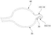
图2是本申请的捕获装置在心脏瓣膜捕获预引导装置的示意图;Fig. 2 is a schematic diagram of the capturing device of the present application capturing the pre-guiding device in the heart valve;
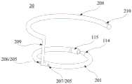
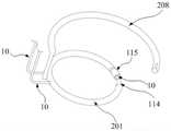
图3-4分别是本申请一种心脏瓣膜定位系统的一实施例的立体图和俯视图;3-4 are respectively a perspective view and a top view of an embodiment of a heart valve positioning system of the present application;
图5是本申请的预引导装置穿设于第一定位结构的示意图;Fig. 5 is a schematic diagram of the pre-guiding device of the present application passing through the first positioning structure;
图6是本申请的第一定位结构的锁紧结构处于锁紧状态形成封闭的环的一实施例的示意图;Fig. 6 is a schematic diagram of an embodiment in which the locking structure of the first positioning structure of the present application is in a locked state to form a closed loop;
图7是本申请的人工心脏瓣膜系统释放之后的一实施例的示意图;Fig. 7 is a schematic diagram of an embodiment after the artificial heart valve system of the present application is released;
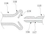
图8A-8B分别是本申请的锁紧结构的第一实施例处于非锁紧和锁紧状态的示意图;8A-8B are schematic diagrams of the first embodiment of the locking structure of the present application in an unlocked state and a locked state, respectively;
图9A是本申请的锁紧结构的第二实施例处于非锁紧和锁紧中的状态示意图;Fig. 9A is a schematic diagram of the state of the second embodiment of the locking structure of the present application in unlocking and locking;
图9B是图9A所示的本申请的锁紧结构的实施例处于锁紧状态的剖视图;Fig. 9B is a cross-sectional view of the embodiment of the locking structure of the present application shown in Fig. 9A in a locked state;
图10是本申请的锁紧结构的第三实施例处于锁紧状态的剖视图;Fig. 10 is a cross-sectional view of the third embodiment of the locking structure of the present application in a locked state;
图11-13分别是本申请的锁紧结构的第四-第六实施例处于锁紧状态的剖视图。11-13 are cross-sectional views of the fourth-sixth embodiments of the locking structure of the present application in a locked state, respectively.
元件标号Component number
10:预引导装置;20:定位装置;201:第一定位结构;202:锁紧结构;203:第一端部;204:第二端部;205:穿设部;101:本体;102:第三端部;30:捕获装置;40:第一辅助导管;50:第二辅助导管;206:第一穿设部;207:第二穿设部;208:第二定位结构;209:连接体;210:连接件;接收体114;配合体115;116:扩张部;117:收缩部;118:第一延伸部;119:第二延伸部;120:凸台;121:弹片;122:第一凸起;123:第一凹槽;124:第二凸起;125:人工瓣膜;126:支撑件;127:输送系统;128:输送管道;129:延伸部;130:开口。10: pre-guiding device; 20: positioning device; 201: first positioning structure; 202: locking structure; 203: first end; 204: second end; 205: piercing part; 101: body; 102: 30: capture device; 40: first auxiliary catheter; 50: second auxiliary catheter; 206: first piercing part; 207: second piercing part; 208: second positioning structure; 209: connection body; 210: connector; receiving
具体实施方式Detailed ways
为了使本领域的人员更好地理解本申请实施例中的技术方案,下面将结合本申请实施例中的附图,对本申请实施例中的技术方案进行清楚、完整地描述,显然,所描述的实施例仅是本申请实施例一部分实施例,而不是全部的实施例。基于本申请实施例中的实施例,本领域普通技术人员所获得的所有其他实施例,都应当属于本申请实施例保护的范围。In order to enable those skilled in the art to better understand the technical solutions in the embodiments of the present application, the following will clearly and completely describe the technical solutions in the embodiments of the present application in conjunction with the drawings in the embodiments of the present application. Obviously, the described The embodiments are only some of the embodiments of the present application, but not all of them. All other embodiments obtained by persons of ordinary skill in the art based on the embodiments in the embodiments of the present application shall fall within the protection scope of the embodiments of the present application.
所述的“远端”是指当将定位装置植入心脏时,植入或靠近心脏的一端。所述的“近端”是指当将定位装置植入心脏时,远离心脏的一端。The "distal end" refers to the end implanted in or close to the heart when the positioning device is implanted in the heart. The "proximal end" refers to the end away from the heart when the positioning device is implanted into the heart.
下面结合本申请实施例附图进一步说明本申请实施例具体实现。The specific implementation of the embodiment of the present application will be further described below in conjunction with the accompanying drawings of the embodiment of the present application.
参见图1至图13,在本申请一具体实现中,提供一种心脏瓣膜定位系统,其可经由输送系统输送至心脏瓣膜,其中,该心脏瓣膜包括原生瓣叶和原生瓣环,该心脏瓣膜定位系统包括:预引导装置10,其可经由该输送系统输送至心脏瓣膜,并捕获原生瓣叶;定位装置20,其包括:管状第一定位结构201和锁紧结构202,该第一定位结构201设有第一端部203、第二端部204以及穿设部205,该第一端部203和该第二端部204在输送状态下相互分离,该穿设部205供该预引导装置10穿入该第一定位结构201的内腔,以使该第一端部203和该第二端部204在该预引导装置10的引导下通过该锁紧结构202相互连接,而令该第一定位结构201形成封闭的环,以将至少一部分原生瓣叶收拢于该封闭的环的内侧。穿设部205可将第一定位结构201分为两部分,例如两个半环,这两部分的内腔可以相通或不相通。Referring to Figures 1 to 13, in a specific implementation of the present application, a heart valve positioning system is provided, which can be delivered to a heart valve via a delivery system, wherein the heart valve includes a native valve leaflet and a native valve ring, and the heart valve The positioning system includes: a
预引导装置10在输送状态下为线性体,在释放后捕获原生瓣叶后形成一个环形。如图1所示,在一实施例中,预引导装置10具有本体101以及设于该本体101两端的第三端部102和第四端部,在输送状态下,第三端部102和第四端部分离。该第三端部102用于经由该输送系统输送至心脏瓣膜,并带动该本体101捕获原生瓣叶,该第四端部位于患者体外;该心脏瓣膜定位系统还包括捕获装置30,其用于经由该输送系统输送至心脏瓣膜,捕获该第三端部102并将该第三端部102拖出患者体外,同时捕获装置30也完全拖出患者体外,此时,预引导装置10捕获原生瓣叶后形成接近于环形的形状。本体101可以为线性体,例如导丝,或者其他形状的结构。第三端部102可以设有辅助捕获结构,便于被捕获装置30抓捕。辅助捕获结构可以与预引导装置10为一体结构,可以由预引导装置10的第三端部102弯曲塑形而形成J型、S型、螺旋状等形状。辅助捕获结构还可以与预引导装置10为分体式,两者通过粘结、焊接、铆接等方式连接在一起,形成球形、柱形、J型、S型、螺旋状等形状。The
在一实施例中,预引导装置10和捕获装置30可以由记忆材料制成,预先制成弧形,例如半圆的形状,当在心脏瓣膜释放后,预引导装置10和捕获装置30形成半圆形,捕获装置30可以很容易地捕获预引导装置10。In one embodiment, the
在另一实施例中,如图1所示,心脏瓣膜定位系统还包括:第一辅助导管40,其用于供该预引导装置10穿过;以及第二辅助导管50,用于供该捕获装置30穿过,以捕获从该第一辅助导管40穿出的该第三端部102,并将该第三端部102拖出患者体外;其中,该第一辅助导管40和该第二辅助导管50被构造成在释放状态下各自弯曲成弧形,且在该第三端部102被拖出患者体外后从患者体内撤出。第一辅助导管40和第二辅助导管50可以具有一定的硬度,并预先形成弧形。In another embodiment, as shown in FIG. 1, the heart valve positioning system further includes: a first
第一辅助导管40和第二辅助导管50的远端可以为自由端,以便于调节弯曲角度,以贴合原生瓣膜的结构。第一辅助导管40和第二辅助导管50在释放后分别沿原生瓣叶的前瓣叶和后瓣叶延伸,直至两者的远端相互接近,之后位于第二辅助导管50中的捕获装置30伸出去抓捕位于第一辅助导管40中的预引导装置10的第三端部102,将第三端部102捕入第二辅助导管50中并拉出体外,最后将第一辅助导管40和第二辅助导管50撤出体内,使得预引导装置10在心室内形成一个环形导向结构。The distal ends of the first
第一定位结构201形成封闭的环后,预引导装置10可自该穿设部205撤出。After the
定位装置可以仅由第一定位结构201独立完成原生瓣叶的捕获和锚定。在另一实施例中,定位装置包括第一定位结构201、第二定位结构208以及连接体209,其中,该第二定位结构208和该连接体209均为空心的管状结构或实心的柱体,该第一定位结构201和该第二定位结构208通过该连接体209连接形成弯折结构,在释放状态下该第一定位结构201和该第二定位结构208各自形成弯曲结构,且该第二定位结构208锚定于原生瓣环的内侧。第二定位结构208上可以设有连接件210与输送系统可拆卸连接。连接件210可以为一穿孔、卡槽或其他类似结构。穿设部205可设于第一定位结构201靠近连接体209的位置,以便于从患者体内撤出。第一定位结构201、第二定位结构208以及连接体209的表面可以包覆有良好的生物相容性高分子覆膜。The positioning device can independently capture and anchor the native leaflet only by the
如图4所示,第二定位结构208的直径不小于该第一定位结构201的直径,以使第二定位结构208可以更牢固地锚定于原生瓣环的内侧。第一定位结构201的宽度>该第二定位结构208的宽度,且该第一定位结构201的宽度>该连接体209的宽度,以加强第一定位结构201捕获原生瓣叶后的稳定性,以及增强第一定位结构201对人工瓣膜的支撑力。但第一定位结构201的宽度不限于此,也可以小于或等于第二定位结构208的宽度。所述的“宽度”是指第一定位结构201或第二定位结构208的横截面的直径或最大尺寸。As shown in FIG. 4 , the diameter of the
穿设部205可以设置一个穿孔或两个穿孔。如图3所示,在一实施例中,穿设部205设置两个穿孔,包括第一穿设部206和第二穿设部207,第一穿设部206用于供该预引导装置10的该第三端部102穿入而进入该第一定位结构201的内腔;第二穿设部207,其用于供该预引导装置10的该第三端部102自该第一定位结构201的内腔穿出。在另一实施例中,穿设部可以设置一个穿孔,预引导装置10的第三端部102进入和穿出均经过这一个穿孔。The piercing portion 205 may be provided with one or two piercing holes. As shown in FIG. 3 , in one embodiment, the piercing portion 205 is provided with two perforations, including a first piercing portion 206 and a second piercing portion 207, the first piercing portion 206 is used for the
在一实施例中,如图5-6,图8A-14所示,锁紧结构202包括接收体114和配合体115,该接收体114和该配合体115分别设于该第一端部203和该第二端部204中的其中一者,例如接收体114设于第一端部203,配合体115设于第二端部204,或者两者互换,该接收体114和该配合体115可相互配合连接,且该配合体115的外径<该接收体114的内径,以使该接收体114和该配合体115相互配合连接时,该配合体115进入该接收体114的内部。In one embodiment, as shown in FIGS. 5-6 and 8A-14, the locking structure 202 includes a receiving
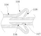
在一实施例中,如图8A-10所示,该接收体114具有延伸部,该配合体115具有扩张部116和收缩部117,该扩张部116的外径>该收缩部117的外径;当该接收体114和该配合体115处于对接状态时,该扩张部116向该延伸部施加扩张作用力,以使该延伸部的内径扩大且该配合体115进入该接收体114;当该接收体114和该配合体115处于卡合状态时,该延伸部与该收缩部117卡接,该延伸部的内径恢复至初始状态。In one embodiment, as shown in FIGS. 8A-10 , the receiving
如图8A-9B所示,在一实施例中,延伸部包括:第一延伸部118,其自该第一端部203沿径向向外延伸;以及第二延伸部119,其具有弹性,且该第二延伸部119自该第一延伸部118的端部沿径向向内延伸,以使该第一延伸部118和该第二延伸部119共同形成喇叭状结构。第一延伸部118和第二延伸部119其中之一或两者均可具有弹性。收缩部117可以为凹槽,凹槽可以带有弧度或没有弧度,扩张部116的端部可以为锥形结构,更加利于将扩张部116推进接收体114中。当配合体115进入接收体114的内部时,扩张部116沿径向向外挤压第二延伸部119,第二延伸部119带动第一延伸部118一并扩张,使得扩张部116进入接收体114的内腔,直至第二延伸部119卡合于收缩部117中,从而实现第一端部203与第二端部204相互锁定,使第一定位结构201形成封闭的环。As shown in FIGS. 8A-9B , in one embodiment, the extension includes: a
如图9A-10所示,在一实施例中,延伸部129自该第一端部203沿径向向内延伸,且该第一端部203的侧壁设有至少一个开口130。扩张部116的端部为锥形结构。当配合体115进入接收体114的内部时,扩张部116沿径向向外挤压延伸部使开口130变大,使得扩张部116进入接收体114的内腔,直至延伸部129卡合于收缩部117中,从而实现第一端部203与第二端部204相互锁定,使第一定位结构201形成封闭的环。As shown in FIGS. 9A-10 , in one embodiment, the
如图10所示,在一实施例中,该配合体115具有凸台120,该接收体114的内侧壁设有一个或多个弹片121,该弹片121自该内侧壁沿径向向内延伸;当该接收体114和该配合体115处于对接状态时,该凸台120向该弹片121施加压力,以使该弹片121被挤压后越过该凸台120;当该接收体114和该配合体115处于卡合状态时,该弹片121恢复至扩展状态且卡合于该凸台120的内侧。As shown in FIG. 10 , in one embodiment, the
在一实施例中,该接收体114和该配合体115分别设有第一凸起122和第一凹槽123中的其中一者,如图11所示,接收体114设有第一凸起122,配合体115设有第一凹槽123;如图12所示,接收体114设有第一凹槽123,配合体115设有第一凸起122。当该接收体114和该配合体115对接时,该第一凸起122进入该第一凹槽123中,使第一端部203与第二端部204相互锁定,进而使第一定位结构201形成封闭的环。In one embodiment, the receiving
在一实施例中,如图13所示该接收体114设有第二凸起124,当该接收体114和该配合体115对接时,该第二凸起124与该配合体115的外表面卡接,使第一端部203与第二端部204相互锁定,进而使第一定位结构201形成封闭的环。In one embodiment, the receiving
如图7所示,在一实施例中,本申请还提供一种人工心脏瓣膜系统,该系统包括:上述的心脏瓣膜定位系统和人工瓣膜125,该人工瓣膜125包括:人工瓣叶;以及筒状支撑件126,该人工瓣叶周向固定于该支撑件126的内侧,且该支撑件126与定位装置20相适配,以当定位装置20释放后,将该人工瓣膜125植入该第一定位结构201的内侧。在另一实施例中,本申请还提供一种人工心脏瓣膜植入系统,其包括人工心脏瓣膜系统和输送系统127,输送系统127具有输送管道128,用于将该心脏瓣膜定位装置20输送至心脏瓣膜后进行释放,输送系统127可以包括一套或多套包含输送管道128的结构。As shown in Figure 7, in one embodiment, the present application also provides an artificial heart valve system, which includes: the above-mentioned heart valve positioning system and an artificial valve 125, the artificial valve 125 includes: artificial valve leaflets; and a tube shaped support 126, the artificial valve leaflet is circumferentially fixed on the inner side of the support 126, and the support 126 is adapted to the
输送时输送管道128可以位于瓣叶连合处C1或C2处,若定位装置20从C1处释放,第二定位结构208设计为逆时针旋转,若定位装置20从C2释放,第二定位结构208设计为顺时针旋转。定位装置20释放后,第二定位结构208位于后瓣环部位,实现定位装置20在原生瓣环处良好的固定。During delivery, the delivery pipeline 128 can be located at the leaflet commissure C1 or C2. If the
在另又一实施例中,本申请还提供一种人工心脏瓣膜系统的植入方法,该植入方法包括:在将该预引导装置10经由该输送系统127输送至心脏瓣膜之后,该捕获装置30经由该输送系统127输送至心脏瓣膜,捕获该第三端部102并带动该本体101捕获原生瓣叶后将该第三端部102拖出患者体外;在患者体外将该预引导装置10的该第三端部102经该第一穿设部206穿入该第一定位结构201的内腔,再经该第二穿设部207自该第一定位结构201的内腔穿出;将第一定位结构201经房间隔输送至原生瓣叶连合处后缓慢释放,使该第一端部和该第二端部204在该预引导装置10的引导下通过该锁紧结构202相互连接,使该第一定位结构201环绕原生瓣叶移动形成一个封闭的环,并将至少一部分原生瓣叶收拢于该封闭的环的内侧;撤出该预引导装置10,释放该连接体209和该第二定位结构208;将该人工瓣膜经房间隔输送至该第一定位结构201的内侧并释放。In yet another embodiment, the present application also provides an implantation method of an artificial heart valve system, the implantation method comprising: after delivering the
在另一实施例中,首先将输送系统127经房间隔输送至左心房,调整输送系统127的远端,使其穿过瓣叶连合处C2进入左心室,随后将第一辅助导管40和第二辅助导管50同时通过输送系统127输送至左心室接近瓣口的位置,将第一辅助导管40和第二辅助导管50的远端从输送系统127推出,确保第一辅助导管40和第二辅助导管50的远端位于原生瓣叶外侧后,将第一辅助导管40和第二辅助导管50贴着原生瓣叶外侧推出,直至第一辅助导管40和第二辅助导管50的远端相互接近后,将位于第一辅助导管40中的预引导装置10的第三端部102和第二辅助导管50中的捕获装置30的远端推出,操作位于体外的预引导装置10的第四端部和捕获装置30的近端,使用捕获装置30抓捕预引导装置10的第三端部102,抓捕成功后,将预引导装置10的第三端部102带入第二辅助导管50中直至带出体外,使得预引导装置10在心室内形成环形导向结构,随后将第一辅助导管40和第二辅助导管50从体内撤出。In another embodiment, the delivery system 127 is firstly delivered to the left atrium through the interatrial septum, the distal end of the delivery system 127 is adjusted so that it enters the left ventricle through the leaflet commissure C2, and then the first
之后将在体外的预引导装置10的第三端部102从该第一穿设部206穿入该第一定位结构201的内腔,再经该第二穿设部207自该第一定位结构201的内腔穿出,再将输送系统127与第二定位结构208的连接件相连,随后将第一定位结构201从输送系统127中释放出来,使其沿着预引导装置10在心室形成的环形导向结构滑动,直至锁紧结构202的接收体和配合体相互接近,固定输送系统127的远端,向外拉动预引导装置10,使得环形导向结构直径减小,从而使接收体和配合体相对移动直至卡合,使得第一定位结构201形成一个封闭环,将原生瓣叶收拢在封闭环的内部。Afterwards, the third end 102 of the
之后将第二定位结构208从输送系统中释放,随后撤出预引导装置10,在人工瓣膜释放前,原生瓣叶仍然可以正常活动,保持正常的血液动力学。人工瓣膜可以被释放在第一定位结构201的封闭环内部,通过两者之间的径向作用力固定在原生瓣膜处,替代原生瓣膜的功能。Afterwards, the
相对于现有技术,本申请的人工瓣膜125尺寸较小,可以避免因植入尺寸较大的人工瓣膜125而引起输送时血管并发症及植入后人工瓣叶过早衰败等问题。另外,本申请的人工瓣膜125具有较低的瓣下高度,可以避免阻挡左室流出道,引起左室流出道梗阻的发生。其次,本申请的第一定位结构201可以通过锁紧结构202形成一个封闭环,将原生瓣叶夹持在第一定位结构201和人工瓣膜125之间,利用原生瓣叶组织与第一定位结构201和人工瓣膜125之间的贴合来实现良好的密封效果,避免人工瓣膜125植入后瓣周漏的发生。Compared with the prior art, the artificial valve 125 of the present application is smaller in size, which can avoid problems such as vascular complications during delivery and premature failure of artificial valve leaflets after implantation caused by implanting a larger artificial valve 125 . In addition, the artificial valve 125 of the present application has a lower subvalvular height, which can avoid blocking the left ventricular outflow tract and causing left ventricular outflow tract obstruction. Secondly, the
若定位装置20和人工瓣膜125分别经主动脉和经房间隔两个通路输送,操作复杂,并且有损伤主动脉瓣的风险,本申请中的定位装置20和人工瓣膜125从同一通路经房间隔输送,可以避免引起主动脉瓣的损伤。If the
另外,本申请的预引导装置与第一、第二辅助导管的配合使得预引导装置的捕获较为简单,手术操作难度也随之降低。In addition, the cooperation of the pre-guiding device of the present application with the first and second auxiliary catheters makes the capture of the pre-guiding device relatively simple, and the difficulty of operation is also reduced accordingly.
最后应说明的是:以上实施例仅用以说明本申请实施例的技术方案,而非对其限制;尽管参照前述实施例对本申请进行了详细的说明,本领域的普通技术人员应当理解:其依然可以对前述各实施例所记载的技术方案进行修改,或者对其中部分技术特征进行等同替换;而这些修改或者替换,并不使相应技术方案的本质脱离本申请各实施例技术方案的精神和范围。Finally, it should be noted that: the above embodiments are only used to illustrate the technical solutions of the embodiments of the present application, and are not intended to limit them; although the application has been described in detail with reference to the foregoing embodiments, those of ordinary skill in the art should understand that: It is still possible to modify the technical solutions described in the foregoing embodiments, or perform equivalent replacements for some of the technical features; and these modifications or replacements do not make the essence of the corresponding technical solutions deviate from the spirit and spirit of the technical solutions of the various embodiments of the present application. scope.
Claims (20)
Priority Applications (1)
| Application Number | Priority Date | Filing Date | Title |
|---|---|---|---|
| CN202211511447.6ACN115844592B (en) | 2022-11-29 | 2022-11-29 | Heart valve positioning device, artificial heart valve system, implantation system and method |
Applications Claiming Priority (1)
| Application Number | Priority Date | Filing Date | Title |
|---|---|---|---|
| CN202211511447.6ACN115844592B (en) | 2022-11-29 | 2022-11-29 | Heart valve positioning device, artificial heart valve system, implantation system and method |
Publications (2)
| Publication Number | Publication Date |
|---|---|
| CN115844592Atrue CN115844592A (en) | 2023-03-28 |
| CN115844592B CN115844592B (en) | 2025-09-16 |
Family
ID=85667782
Family Applications (1)
| Application Number | Title | Priority Date | Filing Date |
|---|---|---|---|
| CN202211511447.6AActiveCN115844592B (en) | 2022-11-29 | 2022-11-29 | Heart valve positioning device, artificial heart valve system, implantation system and method |
Country Status (1)
| Country | Link |
|---|---|
| CN (1) | CN115844592B (en) |
Cited By (1)
| Publication number | Priority date | Publication date | Assignee | Title |
|---|---|---|---|---|
| CN119424048A (en)* | 2023-08-04 | 2025-02-14 | 杭州德晋医疗科技有限公司 | Cardiac implants and implant systems |
Citations (10)
| Publication number | Priority date | Publication date | Assignee | Title |
|---|---|---|---|---|
| US20110218620A1 (en)* | 2010-03-05 | 2011-09-08 | Edwards Lifesciences Corporation | Retaining Mechanisms for Prosthetic Valves |
| WO2012063228A1 (en)* | 2010-11-12 | 2012-05-18 | Ht Consultant Di Giovanni Righini | Prosthesis for cardiovascular valve |
| WO2013150512A1 (en)* | 2012-04-05 | 2013-10-10 | Mvalve Technologies Ltd. | Cardiac valve support structure |
| US20150245910A1 (en)* | 2012-11-20 | 2015-09-03 | Giovanni Righini | Device for the Deployment of a System of Guide Wires Within a Cardiac Chamber for Implanting a Prosthetic Heart Valve |
| US20160228252A1 (en)* | 2015-02-09 | 2016-08-11 | Edwards Lifesciences Corporation | Low profile transseptal catheter and implant system for minimally invasive valve procedure |
| US20160346080A1 (en)* | 2014-02-04 | 2016-12-01 | INNOVHEART S.r.I. | Prosthetic device for a heart valve |
| US20180177594A1 (en)* | 2016-08-26 | 2018-06-28 | Edwards Lifesciences Corporation | Heart valve docking devices and systems |
| US20190290432A1 (en)* | 2018-03-20 | 2019-09-26 | Medtronic Vascular, Inc. | Prolapse prevention device and methods of use thereof |
| CN114869544A (en)* | 2022-03-31 | 2022-08-09 | 上海纽脉医疗科技股份有限公司 | Valve leaflet capturing device and system and artificial heart valve |
| CN114948345A (en)* | 2022-06-08 | 2022-08-30 | 上海汇禾医疗科技有限公司 | Heart valve positioning device, heart valve replacement component and implantation method |
- 2022
- 2022-11-29CNCN202211511447.6Apatent/CN115844592B/enactiveActive
Patent Citations (10)
| Publication number | Priority date | Publication date | Assignee | Title |
|---|---|---|---|---|
| US20110218620A1 (en)* | 2010-03-05 | 2011-09-08 | Edwards Lifesciences Corporation | Retaining Mechanisms for Prosthetic Valves |
| WO2012063228A1 (en)* | 2010-11-12 | 2012-05-18 | Ht Consultant Di Giovanni Righini | Prosthesis for cardiovascular valve |
| WO2013150512A1 (en)* | 2012-04-05 | 2013-10-10 | Mvalve Technologies Ltd. | Cardiac valve support structure |
| US20150245910A1 (en)* | 2012-11-20 | 2015-09-03 | Giovanni Righini | Device for the Deployment of a System of Guide Wires Within a Cardiac Chamber for Implanting a Prosthetic Heart Valve |
| US20160346080A1 (en)* | 2014-02-04 | 2016-12-01 | INNOVHEART S.r.I. | Prosthetic device for a heart valve |
| US20160228252A1 (en)* | 2015-02-09 | 2016-08-11 | Edwards Lifesciences Corporation | Low profile transseptal catheter and implant system for minimally invasive valve procedure |
| US20180177594A1 (en)* | 2016-08-26 | 2018-06-28 | Edwards Lifesciences Corporation | Heart valve docking devices and systems |
| US20190290432A1 (en)* | 2018-03-20 | 2019-09-26 | Medtronic Vascular, Inc. | Prolapse prevention device and methods of use thereof |
| CN114869544A (en)* | 2022-03-31 | 2022-08-09 | 上海纽脉医疗科技股份有限公司 | Valve leaflet capturing device and system and artificial heart valve |
| CN114948345A (en)* | 2022-06-08 | 2022-08-30 | 上海汇禾医疗科技有限公司 | Heart valve positioning device, heart valve replacement component and implantation method |
Cited By (1)
| Publication number | Priority date | Publication date | Assignee | Title |
|---|---|---|---|---|
| CN119424048A (en)* | 2023-08-04 | 2025-02-14 | 杭州德晋医疗科技有限公司 | Cardiac implants and implant systems |
Also Published As
| Publication number | Publication date |
|---|---|
| CN115844592B (en) | 2025-09-16 |
Similar Documents
| Publication | Publication Date | Title |
|---|---|---|
| US12329640B2 (en) | System and method for transaortic delivery of a prosthetic heart valve | |
| US11602430B2 (en) | Valve suturing and implantation procedures | |
| US20240180703A1 (en) | Transcatheter artificial cusp for valve insufficiency | |
| CN110013351B (en) | Heart valve prosthesis delivery system | |
| KR102693746B1 (en) | Heart valve sealing devices and delivery devices therefor | |
| US20250186205A1 (en) | Delivery systems for cardiac valve devices | |
| CN111643226B (en) | Systems and methods for transcatheter treatment of valvular regurgitation | |
| WO2016004799A1 (en) | Cardiac valve implantation instrument with anchoring device | |
| CN111200995A (en) | Prosthetic spacer device for heart valves | |
| CN110141399A (en) | Prosthetic valve with axial sliding frame | |
| JP7535096B2 (en) | Apparatus and method for assembling a heart valve prosthesis | |
| CN114948345A (en) | Heart valve positioning device, heart valve replacement component and implantation method | |
| CN117653414A (en) | Artificial atrioventricular heart valve system and apparatus | |
| CN218922889U (en) | Implant for heart valve annulus repair and delivery device for implant | |
| CN111374798A (en) | Interventional guiding device | |
| US20240277468A1 (en) | Heart valve repair prostheses, delivery devices and methods | |
| CN115844592A (en) | Heart valve positioning device, artificial heart valve system, implantation system and method | |
| CN115969576B (en) | Heart valve positioning device, artificial heart valve system, implantation system and method | |
| CN115300184A (en) | Heart valve positioning device, artificial heart valve system, implantation system and method | |
| US20210251749A1 (en) | Device for implanting a prosthesis for a heart valve and assembly procedure | |
| EP4117584A1 (en) | Transcatheter valve leaflet replacement device, delivery, guiding and fixation system and method for same | |
| JP7535097B2 (en) | Device for placing guidewires around heart valves | |
| CN113905691B (en) | Delivery system for heart valve devices | |
| CN117752464A (en) | Implant for heart valve annulus repair and delivery device for implant | |
| HK40042111A (en) | Transcatheter artificial cusp for valve insufficiency |
Legal Events
| Date | Code | Title | Description |
|---|---|---|---|
| PB01 | Publication | ||
| PB01 | Publication | ||
| SE01 | Entry into force of request for substantive examination | ||
| SE01 | Entry into force of request for substantive examination | ||
| GR01 | Patent grant | ||
| GR01 | Patent grant |