CN115841124A - External bar code reading device and reading method - Google Patents
External bar code reading device and reading methodDownload PDFInfo
- Publication number
- CN115841124A CN115841124ACN202211621387.3ACN202211621387ACN115841124ACN 115841124 ACN115841124 ACN 115841124ACN 202211621387 ACN202211621387 ACN 202211621387ACN 115841124 ACN115841124 ACN 115841124A
- Authority
- CN
- China
- Prior art keywords
- reading
- window
- external
- bar code
- equipment
- Prior art date
- Legal status (The legal status is an assumption and is not a legal conclusion. Google has not performed a legal analysis and makes no representation as to the accuracy of the status listed.)
- Pending
Links
Images


Landscapes
- Telephone Set Structure (AREA)
Abstract
Translated fromChinese
Description
Translated fromChinese技术领域technical field
本发明涉及条码识读领域,具体地说涉及一种外置条码识读设备及识读方法。The invention relates to the field of barcode reading, in particular to an external barcode reading device and a reading method.
背景技术Background technique
条码识读设备指的是用来读取条码信息的设备。它使用一个光学装置将条码的条空信息转换,成电子信息,再由专用译码器翻译成相应的数据信息。因其输入速度快、可靠性高、采集信息量大、灵活实用的有点,在商品流通、图书管理、邮电管理、银行系统等许多领域上,条码识读设备都得到了广泛的应用。Barcode reading equipment refers to equipment used to read barcode information. It uses an optical device to convert the space information of the bar code into electronic information, and then translates it into corresponding data information by a dedicated decoder. Because of its fast input speed, high reliability, large amount of collected information, and flexible and practical features, barcode reading equipment has been widely used in many fields such as commodity circulation, book management, post and telecommunications management, and banking systems.
条码识读设备因为具有优化的专业识读算法,识读效率高,且能适应不同的使用场景,不过此类设备成本较高,所以在一些非典型领域的从业人员因为扫码频率不高,且受限于采购预算等情况,普遍采用个人或工作手机作为识读条码的手段。但普通手机所安装的各类条码识读软件采用开源算法,仅能识别条件良好的条码,且识读速度低,长时间通过亮屏扫码影响手机续航。尤其面对折皱,污损,畸变等复杂情况的条码时,甚至无法完成识别。Because of the optimized professional reading algorithm, the barcode reading equipment has high reading efficiency and can adapt to different usage scenarios. However, the cost of such equipment is relatively high, so practitioners in some atypical fields do not scan codes frequently. And limited by the procurement budget and other circumstances, personal or work mobile phones are generally used as a means of reading barcodes. However, all kinds of barcode reading software installed on ordinary mobile phones use open source algorithms, which can only recognize barcodes with good conditions, and the reading speed is low, and scanning codes with bright screens for a long time will affect the battery life of mobile phones. Especially when faced with complex barcodes such as wrinkles, stains, and distortions, it is even impossible to complete the recognition.
发明内容Contents of the invention
为此,本发明要解决的技术问题是针对上述现有技术的不足,提供一种外置条码识读设备及其识读方法,通过在移动设备上附加外置条码识读设备,有效利用移动设备平台,提高识读效率。Therefore, the technical problem to be solved by the present invention is to provide an external barcode reading device and its reading method for the above-mentioned deficiencies in the prior art. By adding an external barcode reading device to the mobile device, the mobile Equipment platform to improve reading efficiency.
为解决上述技术问题,本发明的所采用的技术方案:In order to solve the problems of the technologies described above, the adopted technical solution of the present invention:
技术方案一Technical solution one
一种外置条码识读设备,包括:An external barcode reading device, comprising:
壳体:所述壳体包括上壳体和下壳体,所述壳体呈L型;Shell: the shell includes an upper shell and a lower shell, and the shell is L-shaped;
所述上壳体包括主面板,以及与所述主面板呈一定角度的识读面板;所述识读面板设置有一识读窗口,所述识读窗口安装有一镜片;The upper casing includes a main panel, and a reading panel at a certain angle to the main panel; the reading panel is provided with a reading window, and a lens is installed on the reading window;
所述下壳体包括底板,以及与所述底板呈一定角度的底座,所述底板上具有导轨;The lower casing includes a base plate and a base at a certain angle to the base plate, and guide rails are provided on the base plate;
扫描组件,所述扫描组件固定于所述底座上,所述扫描组件的识读面正对所述识读窗口的所述镜片;a scanning component, the scanning component is fixed on the base, and the reading surface of the scanning component is facing the mirror of the reading window;
PCB板,所述PCB板固定于所述下壳体的底板上,与所述扫描组件电连接;a PCB board, the PCB board is fixed on the bottom plate of the lower housing and is electrically connected to the scanning component;
USB线连接板,所述USB线连接板位于所述下壳体的底板上,所述USB线连接板通过弹簧沿着所述导轨与所述下壳体进行相对运动;A USB cable connecting plate, the USB cable connecting plate is located on the bottom plate of the lower case, and the USB cable connecting plate moves relative to the lower case along the guide rail through a spring;
带插头的USB线,所述带插头的USB线一端固定于所述USB线连接板,并与所述PCB板通过FPC线进行电连接。A USB cable with a plug, one end of the USB cable with a plug is fixed to the USB cable connecting plate, and is electrically connected to the PCB board through an FPC cable.
所述上壳体还包括:按键窗口,发声设备窗口,指示灯窗口。The upper casing also includes: a button window, a sound-generating device window, and an indicator window.
所述外置条码识读设备还包括:The external barcode reading device also includes:
按键板,所述按键板固定于所述下壳体的底板上,与所述PCB板电连接;a keypad, the keypad is fixed on the bottom plate of the lower housing and is electrically connected to the PCB;
按键,所述按键固定于所述按键板上方,突出部位于所述上壳体的按键窗口,可操作地触发所述按键板;a key, the key is fixed above the key board, and the protruding part is located in the key window of the upper case, and is operable to trigger the key board;
发声设备,所述发声设备固定于所述下壳体的底板上,位于所述上壳体的发声设备窗口下方,与所述PCB板电连接;A sounding device, the sounding device is fixed on the bottom plate of the lower case, located below the window of the sounding device of the upper case, and electrically connected to the PCB board;
指示灯,所述指示灯固定于所述PCB板上,位于所述上壳体的指示灯窗口下方。The indicator light is fixed on the PCB and is located below the indicator window of the upper case.
所述下壳体的背面设置有粘贴组件,可固定于移动设备上。The back of the lower casing is provided with an adhesive component, which can be fixed on the mobile device.
所述下壳体的背面设置有魔术贴,可固定于移动设备上。The back side of the lower case is provided with Velcro, which can be fixed on the mobile device.
所述上壳体的主面板和识读面板呈90度,所述识读面板的背面设置有软性材料。The main panel of the upper casing and the reading panel are at an angle of 90 degrees, and a soft material is arranged on the back of the reading panel.
技术方案二Technical solution two
一种识读方法,包括以下步骤:A reading method, comprising the following steps:
S1:将所述外置条码识读设备安装于移动设备上;S1: Install the external barcode reading device on the mobile device;
S2:将带插头的USB线连接所述移动设备的接口;S2: connecting the USB cable with plug to the port of the mobile device;
S3:触发按键,控制扫描组件获取目标图像并进行解码;S3: Trigger the button to control the scanning component to acquire the target image and decode it;
S4:所述外置条码识读设备通过所述带插头的USB线将解码结果传输给所述移动设备。S4: The external barcode reading device transmits the decoding result to the mobile device through the USB cable with plug.
S2步骤中,当所述移动设备通过接口检测到已连接所述外置条码识读设备时,开始对所述外置条码识读设备进行供电,并与所述外置条码识读设备建立控制信号和数据信号传输通路。In step S2, when the mobile device detects that the external barcode reading device has been connected through the interface, it starts to supply power to the external barcode reading device, and establishes control with the external barcode reading device Signal and data signaling pathway.
S3步骤中,通过触发所述移动设备的音量键或者触发所述移动设备屏幕悬浮窗来发送控制信号传输给所述外置条码识读设备,控制扫描组件获取目标图像并进行解码。In step S3, by triggering the volume key of the mobile device or triggering the floating window on the screen of the mobile device to send a control signal to the external barcode reading device, the scanning component is controlled to acquire the target image and decode it.
本发明具有如下有益效果:The present invention has following beneficial effect:
采用专用条码识读引擎,通过USB连接线使手机等移动设备控制所述条码识读引擎进行扫码并接受解码结果,有效的解决了移动设备的读码短板;通过设置弹簧与USB连接板导轨,实现USB连接线的可伸缩,便于适配不同尺寸的移动设备。可通过移动设备的虚拟按键、实体按键、所述外置条码识读设备按键等多方式实现在不同操作模式下的扫码触发。Using a dedicated barcode reading engine, mobile devices such as mobile phones control the barcode reading engine to scan codes and accept decoding results through USB cables, which effectively solves the shortcoming of code reading on mobile devices; by setting springs and USB connection boards The guide rail realizes the expansion and contraction of the USB cable, which is convenient for adapting to mobile devices of different sizes. Scan code triggering in different operation modes can be realized in multiple ways such as virtual keys of the mobile device, physical keys, and keys of the external barcode reading device.
附图说明Description of drawings
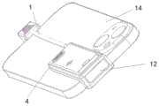
图1为本发明的一种外置条码识读设备的示意图;Fig. 1 is a schematic diagram of an external barcode reading device of the present invention;
图2为本发明的一种外置条码识读设备的爆炸图;Fig. 2 is an exploded view of an external barcode reading device of the present invention;
图3为本发明的一种外置条码识读设备的安装状态图;Fig. 3 is the installation status diagram of a kind of external barcode reading equipment of the present invention;
图4为本发明的一种外置条码识读设备的示意图;Fig. 4 is a schematic diagram of an external barcode reading device of the present invention;
图5为本发明的一种外置条码识读方法的流程图。FIG. 5 is a flow chart of an external barcode reading method of the present invention.
附图标记为:1-带插头的USB线;2-下壳体;3-按键板;4-按键;5-发声设备;6-上壳体;7-USB线连接板;8-PCB板;9-指示灯装饰盖;10-弹簧;11-扫描组件;12-镜片;13-螺丝;14-移动设备。The reference signs are: 1-USB line with plug; 2-lower housing; 3-key board; 4-key; 5-sound-generating equipment; 6-upper housing; ; 9-light decoration cover; 10-spring; 11-scanning component; 12-lens; 13-screw; 14-mobile device.
具体实施方式Detailed ways
下面结合附图和具体实施例来对本发明进行详细的说明。The present invention will be described in detail below in conjunction with the accompanying drawings and specific embodiments.
实施例1Example 1
如图1-4所示,一种外置条码识读设备,包括:As shown in Figure 1-4, an external barcode reading device includes:
壳体:所述壳体包括上壳体6和下壳体2,所述壳体呈L型;Shell: the shell includes an upper shell 6 and a
所述上壳体6包括主面板,以及与所述主面板呈一定角度的识读面板;所述识读面板设置有一识读窗口,所述识读窗口安装有一镜片12;The upper casing 6 includes a main panel, and a reading panel at a certain angle with the main panel; the reading panel is provided with a reading window, and a
所述下壳体2包括底板,以及与所述底板呈一定角度的底座,所述底板上具有导轨;The
扫描组件11,所述扫描组件11固定于所述底座上,所述扫描组件11的识读面正对所述识读窗口的所述镜片12;A
PCB板8,所述PCB板8固定于所述下壳体2的底板上,与所述扫描组件11电连接;PCB board 8, said PCB board 8 is fixed on the bottom plate of said
USB线连接板7,所述USB线连接板7位于所述下壳体2的底板上,所述USB线连接板7通过弹簧10沿着所述导轨与所述下壳体2进行相对运动;USB line connection plate 7, the USB line connection plate 7 is located on the bottom plate of the
带插头的USB线1,所述带插头的USB线1一端固定于所述USB线连接板7,并与所述PCB板8通过FPC线进行电连接。A
所述上壳体6还包括:按键窗口,发声设备窗口,指示灯窗口。The upper casing 6 also includes: a button window, a sound-generating device window, and an indicator window.
所述外置条码识读设备还包括:按键板3,所述按键板3固定于所述下壳体2的底板上,与所述PCB板8电连接;按键4,所述按键4固定于所述按键板3上方,突出部位于所述上壳体6的按键窗口,可操作地触发所述按键板3;发声设备5,所述发声设备5固定于所述下壳体2的底板上,位于所述上壳体6的发声设备窗口下方,与所述PCB板8电连接;The external barcode reading device also includes: a
指示灯,所述指示灯固定于所述PCB板8上,位于所述上壳体6的指示灯窗口下方。The indicator light is fixed on the PCB board 8 and is located below the indicator window of the upper housing 6 .
所述下壳体2的背面设置有粘贴组件,可固定于移动设备14上。The back of the
所述下壳体2的背面设置有魔术贴,可固定于移动设备14上。The back of the
所述上壳体6的主面板和识读面板呈90度,所述识读面板的背面设置有软性材料。The main panel of the upper casing 6 and the reading panel are at an angle of 90 degrees, and a soft material is arranged on the back of the reading panel.
采用专用条码识读引擎,通过USB连接线使手机等移动设备控制所述条码识读引擎进行扫码并接受解码结果,有效的解决了移动设备的读码短板;通过设置弹簧与USB连接板导轨,实现USB连接线的可伸缩,便于适配不同尺寸的移动设备。可通过移动设备的虚拟按键、实体按键、所述外置条码识读设备按键等多方式实现在不同操作模式下的扫码触发。Using a dedicated barcode reading engine, mobile devices such as mobile phones control the barcode reading engine to scan codes and accept decoding results through USB cables, which effectively solves the shortcoming of code reading on mobile devices; by setting springs and USB connection boards The guide rail realizes the expansion and contraction of the USB cable, which is convenient for adapting to mobile devices of different sizes. Scan code triggering in different operation modes can be realized in multiple ways such as virtual keys of the mobile device, physical keys, and keys of the external barcode reading device.
实施例2Example 2
如图5所示,一种识读方法,包括以下步骤:As shown in Figure 5, a reading method includes the following steps:
S1:将所述外置条码识读设备安装于移动设备14上;S1: Install the external barcode reading device on the
S2:将带插头的USB线1连接所述移动设备14的接口;S2: connecting the
S3:触发按键4,控制扫描组件11获取目标图像并进行解码;S3: trigger the
S4:所述外置条码识读设备通过所述带插头的USB线1将解码结果传输给所述移动设备14。S4: The external barcode reading device transmits the decoding result to the
S2步骤中,当所述移动设备14通过接口检测到已连接所述外置条码识读设备时,开始对所述外置条码识读设备进行供电,并与所述外置条码识读设备建立控制信号和数据信号传输通路。In step S2, when the
S3步骤中,通过触发所述移动设备14的音量键或者触发所述移动设备14屏幕悬浮窗来发送控制信号传输给所述外置条码识读设备,控制扫描组件11获取目标图像并进行解码。In step S3, by triggering the volume key of the
采用专用条码识读引擎,通过USB连接线使手机等移动设备控制所述条码识读引擎进行扫码并接受解码结果,有效的解决了移动设备的读码短板;通过设置弹簧与USB连接板导轨,实现USB连接线的可伸缩,便于适配不同尺寸的移动设备。可通过移动设备的虚拟按键、实体按键、所述外置条码识读设备按键等多方式实现在不同操作模式下的扫码触发。Using a dedicated barcode reading engine, mobile devices such as mobile phones control the barcode reading engine to scan codes and accept decoding results through USB cables, which effectively solves the shortcoming of code reading on mobile devices; by setting springs and USB connection boards The guide rail realizes the expansion and contraction of the USB cable, which is convenient for adapting to mobile devices of different sizes. Scan code triggering in different operation modes can be realized in multiple ways such as virtual keys of the mobile device, physical keys, and keys of the external barcode reading device.
以上的实施例只是在于说明而不是限制本发明,故凡依本发明专利申请范围所述的方法所做的等效变化或修饰,均包括于本发明专利申请范围内。The above embodiments are only intended to illustrate rather than limit the present invention, so all equivalent changes or modifications made according to the methods described in the scope of the patent application of the present invention are included in the scope of the patent application of the present invention.
Claims (9)
Priority Applications (1)
| Application Number | Priority Date | Filing Date | Title |
|---|---|---|---|
| CN202211621387.3ACN115841124A (en) | 2022-12-16 | 2022-12-16 | External bar code reading device and reading method |
Applications Claiming Priority (1)
| Application Number | Priority Date | Filing Date | Title |
|---|---|---|---|
| CN202211621387.3ACN115841124A (en) | 2022-12-16 | 2022-12-16 | External bar code reading device and reading method |
Publications (1)
| Publication Number | Publication Date |
|---|---|
| CN115841124Atrue CN115841124A (en) | 2023-03-24 |
Family
ID=85578745
Family Applications (1)
| Application Number | Title | Priority Date | Filing Date |
|---|---|---|---|
| CN202211621387.3APendingCN115841124A (en) | 2022-12-16 | 2022-12-16 | External bar code reading device and reading method |
Country Status (1)
| Country | Link |
|---|---|
| CN (1) | CN115841124A (en) |
Citations (5)
| Publication number | Priority date | Publication date | Assignee | Title |
|---|---|---|---|---|
| CN202854824U (en)* | 2012-07-19 | 2013-04-03 | 深圳市江波龙电子有限公司 | Portable bar code scanning device |
| CN103049727A (en)* | 2012-12-11 | 2013-04-17 | 福建新大陆自动识别技术有限公司 | Bar code recognizing, reading and decoding module and handheld electronic device |
| CN203870631U (en)* | 2014-04-29 | 2014-10-08 | 天津物联传感科技有限公司 | Two-dimensional bar code scanner |
| CN107493364A (en)* | 2017-10-12 | 2017-12-19 | 东莞市映宁轩电子科技有限公司 | A mobile phone case with a charging cable |
| CN114239619A (en)* | 2021-12-16 | 2022-03-25 | 福建新大陆自动识别技术有限公司 | Bar code scanning device with multiple lighting modes |
- 2022
- 2022-12-16CNCN202211621387.3Apatent/CN115841124A/enactivePending
Patent Citations (5)
| Publication number | Priority date | Publication date | Assignee | Title |
|---|---|---|---|---|
| CN202854824U (en)* | 2012-07-19 | 2013-04-03 | 深圳市江波龙电子有限公司 | Portable bar code scanning device |
| CN103049727A (en)* | 2012-12-11 | 2013-04-17 | 福建新大陆自动识别技术有限公司 | Bar code recognizing, reading and decoding module and handheld electronic device |
| CN203870631U (en)* | 2014-04-29 | 2014-10-08 | 天津物联传感科技有限公司 | Two-dimensional bar code scanner |
| CN107493364A (en)* | 2017-10-12 | 2017-12-19 | 东莞市映宁轩电子科技有限公司 | A mobile phone case with a charging cable |
| CN114239619A (en)* | 2021-12-16 | 2022-03-25 | 福建新大陆自动识别技术有限公司 | Bar code scanning device with multiple lighting modes |
Similar Documents
| Publication | Publication Date | Title |
|---|---|---|
| KR101595344B1 (en) | Display module and portable terminal having the same | |
| KR101760746B1 (en) | Mobile terminal | |
| CN105739141B (en) | Flexible circuit board, liquid crystal display module and terminal | |
| CN107770315A (en) | Mobile terminal | |
| US9204534B2 (en) | Panel unit that reduces influence of static electricity, and electronic apparatus | |
| CN201345173Y (en) | Point reading and learning machine based on optical identification | |
| CN110147019A (en) | A multi-color liquid crystal writing board | |
| CN209167758U (en) | A kind of multi-color LCD clipboard | |
| US7251099B2 (en) | Hard disk drive tray structure with flex circuit extending between exposed sides and connected to metal pad and indicator | |
| CN115841124A (en) | External bar code reading device and reading method | |
| TW200813553A (en) | Liquid crystal display device | |
| CN204633841U (en) | A dual-screen display system based on OTG interface | |
| CN219872391U (en) | External bar code reading equipment | |
| US20100258423A1 (en) | Keypad assembly for electronic devices | |
| WO2017071238A1 (en) | Button module for mobile phone soft icon | |
| KR101247682B1 (en) | Window plate, liquid crystal display device and mobile terminal using thereof | |
| CN102339131A (en) | Keyboard, electronic device using same and input method | |
| CN213519273U (en) | Recording apparatus | |
| CN108600446A (en) | Mobile terminal | |
| CN210691438U (en) | A split-screen display access control all-in-one machine | |
| CN205080464U (en) | Infrared touch all -in -one | |
| CN110867009A (en) | Gate inhibition all-in-one machine with split screen display | |
| JP2012133909A (en) | Key input device | |
| CN112859409A (en) | Display panel, display panel assembly and electronic equipment | |
| CN218769206U (en) | Keyboard and electronic equipment |
Legal Events
| Date | Code | Title | Description |
|---|---|---|---|
| PB01 | Publication | ||
| PB01 | Publication | ||
| SE01 | Entry into force of request for substantive examination | ||
| SE01 | Entry into force of request for substantive examination | ||
| CB03 | Change of inventor or designer information | Inventor after:Weng Fei Inventor after:Rao Chengyun Inventor after:Guo Feng Inventor after:Ding Cheng Inventor before:Weng Fei Inventor before:Rao Chengyun Inventor before:Guo Feng Inventor before:Ding Cheng | |
| CB03 | Change of inventor or designer information |