CN115824753A - Cotton fiber sample splitting mechanism and device - Google Patents
Cotton fiber sample splitting mechanism and deviceDownload PDFInfo
- Publication number
- CN115824753A CN115824753ACN202310159878.9ACN202310159878ACN115824753ACN 115824753 ACN115824753 ACN 115824753ACN 202310159878 ACN202310159878 ACN 202310159878ACN 115824753 ACN115824753 ACN 115824753A
- Authority
- CN
- China
- Prior art keywords
- cotton fiber
- plate
- clamping
- needle
- clamping plate
- Prior art date
- Legal status (The legal status is an assumption and is not a legal conclusion. Google has not performed a legal analysis and makes no representation as to the accuracy of the status listed.)
- Granted
Links
Images


Classifications
- Y—GENERAL TAGGING OF NEW TECHNOLOGICAL DEVELOPMENTS; GENERAL TAGGING OF CROSS-SECTIONAL TECHNOLOGIES SPANNING OVER SEVERAL SECTIONS OF THE IPC; TECHNICAL SUBJECTS COVERED BY FORMER USPC CROSS-REFERENCE ART COLLECTIONS [XRACs] AND DIGESTS
- Y02—TECHNOLOGIES OR APPLICATIONS FOR MITIGATION OR ADAPTATION AGAINST CLIMATE CHANGE
- Y02W—CLIMATE CHANGE MITIGATION TECHNOLOGIES RELATED TO WASTEWATER TREATMENT OR WASTE MANAGEMENT
- Y02W30/00—Technologies for solid waste management
- Y02W30/50—Reuse, recycling or recovery technologies
- Y02W30/66—Disintegrating fibre-containing textile articles to obtain fibres for re-use
Landscapes
- Treatment Of Fiber Materials (AREA)
- Sampling And Sample Adjustment (AREA)
Abstract
Description
Translated fromChinese技术领域technical field
本发明涉及一种棉纤维检测技术,尤其涉及的是一种棉纤维样本拆分机构及装置。The invention relates to a cotton fiber detection technology, in particular to a cotton fiber sample splitting mechanism and device.
背景技术Background technique
棉纤维是纺织工业的原料,其纤维品质的优劣直接影响纺织品的质量和产量。棉花纤维品质的分析项目包括纤维长度、纤维强度等。Cotton fiber is the raw material of the textile industry, and its fiber quality directly affects the quality and output of textiles. The analysis items of cotton fiber quality include fiber length, fiber strength and so on.
在对棉纤维品质进行检测时,则需要棉纤维样本,标准化检测流程中,原始送测样本的输入也是比较稳定的,是一团约120g-150g的棉团,这个棉团是原始采摘的棉花经简单弹棉处理后形成的,不可以有剪开或切断的断口。外形尺寸约为100×260×100(mm);现阶段获得样本的方式是通过人工拆分,但是人工拆分效率较低,难以满足快速检测的需求。在开发自动化新方案过程中,也有采用拆棉针盘拆分的,但是该方式容易出现样本在拆分过程中纤维被撕扯断裂,从而导致检测数据的不准确的问题。When testing the quality of cotton fiber, cotton fiber samples are needed. In the standardized testing process, the input of the original test sample is also relatively stable. It is a cotton ball of about 120g-150g. This cotton ball is the original picked cotton. Formed after simple elastic cotton treatment, there must be no cut or cut fracture. The overall size is about 100×260×100 (mm); the way to obtain samples at this stage is through manual splitting, but the efficiency of manual splitting is low and it is difficult to meet the needs of rapid detection. In the process of developing a new automated solution, there is also a method of splitting cotton by needle discs, but this method is prone to the problem that the fibers of the sample are torn and broken during the splitting process, resulting in inaccurate detection data.
如公开号CN114646751A,一种棉纤维自动检测设备,包括颜色与杂质检测装置、抓取机构、拆分机构、长度和强度检测装置、第一样本盒与第二样本盒,所述第一样本盒与所述第二样本盒均用于放置棉纤维样本,所述第一样本盒底部开设有供棉纤维样本外露的颜色检测口和杂质检测口,所述第二样本盒底部开设有供棉纤维样本外露的长度检测口和强度检测口;所述拆棉组件包括拆棉气缸以及与所述拆棉气缸连接的拆棉针盘,所述拆棉气缸用于驱动所述拆棉针盘将位于所述长度检测口以及所述强度检测口处的棉纤维拆下来并使其落入所述送棉管中。For example, the publication number CN114646751A, an automatic detection equipment for cotton fibers, including a color and impurity detection device, a grasping mechanism, a split mechanism, a length and strength detection device, a first sample box and a second sample box, the first Both this box and the second sample box are used to place cotton fiber samples. The bottom of the first sample box is provided with a color detection port and an impurity detection port for cotton fiber samples to be exposed. The bottom of the second sample box is provided with a A length detection port and a strength detection port for exposing cotton fiber samples; the cotton removal assembly includes a cotton removal cylinder and a cotton removal needle plate connected to the cotton removal cylinder, and the cotton removal cylinder is used to drive the cotton removal needle The disc removes the cotton fibers located at the length detection port and the strength detection port and makes them fall into the cotton delivery pipe.
该专利中,通过下压气缸的大压力直接从大样本中部取出样本,需要的压力很大,压力太大又会导致棉纤维断裂,会导致拆分出的样本纤维被撕扯断裂,从而导致检测数据的不准确;且通过下压气缸配合针盘从样本中部拆分出样本,下压式获取样本的方式靠压力直接将一团棉纤维从中间硬压出去,很多时候压不出去,存在样本拆分不干净,导致样本质量不够,从而导致长强检测时容易出现大样本、小样本的情况,一旦频繁出现大样本、小样本,会导致单个样本重复检测,检测时间大幅度增加,影响检测的效率。同时,该专利中还通过强风吹送的方式送入检测口进行检测,而通过强风吹送进行运送难以确保样本送入检测口的位置。In this patent, the sample is directly taken out from the middle of the large sample through the high pressure of the downward pressure cylinder, which requires a lot of pressure. Too much pressure will cause the cotton fiber to break, which will cause the split sample fiber to be torn and broken, resulting in detection. The data is inaccurate; and the sample is split from the middle of the sample through the downward pressure cylinder and the needle disc. The downward pressure method of obtaining the sample relies on pressure to directly press out a group of cotton fibers from the middle. In many cases, it cannot be pressed out, and there are samples The splitting is not clean, resulting in insufficient sample quality, which leads to the situation of large samples and small samples prone to appear in Changqiang detection. Once large samples and small samples occur frequently, it will lead to repeated detection of a single sample, which will greatly increase the detection time and affect the detection. s efficiency. At the same time, in this patent, it is also sent into the detection port by strong wind blowing for detection, but it is difficult to ensure the position of the sample sent into the detection port by means of strong wind blowing.
公开于该背景技术部分的信息仅仅旨在增加对本发明的总体背景的理解,而不应当被视为承认或以任何形式暗示该信息已构成为本领域一般技术人员所公知的现有技术。The information disclosed in this Background section is only intended to increase the understanding of the general background of the present invention, and should not be considered as an acknowledgment or any form of suggestion that the information constitutes the prior art that is already known to those skilled in the art.
发明内容Contents of the invention
本发明所要解决的技术问题在于:如何解决目前对棉花样品拆分过程中,容易出现样本拆分不均匀或纤维被扯断或剪断从而破坏纤维的原有性质,导致检测数据不准确的问题。The technical problem to be solved by the present invention is: how to solve the problem that in the current cotton sample splitting process, the sample splits unevenly or the fiber is torn or cut to destroy the original properties of the fiber, resulting in inaccurate detection data.
本发明通过以下技术手段实现解决上述技术问题的:The present invention realizes solving above-mentioned technical problem by following technical means:
棉纤维样本拆分机构,包括样本盒、两个镜像布置的夹持组件,两个所述夹持组件能够同时水平方向相对或背向运动的位于所述样品盒的两侧,所述夹持组件包括竖直方向相对或背向运动的第一夹板和第二夹板,所述第一夹板的底面连接多个第一针具,所述第二夹板的顶面连接多个第二针具,所述样本盒的两侧包括多个贯穿的长条槽,当对棉纤维进行拆分时,所述第一针具和/或所述第二针具插入所述长条槽内并向两侧运动。Cotton fiber sample splitting mechanism, including a sample box, two clamping assemblies arranged in mirror images, the two clamping assemblies can be positioned on both sides of the sample box for relative or back movement in the horizontal direction at the same time, the clamping assembly The assembly includes a first splint and a second splint that move relative or backward in a vertical direction, the bottom surface of the first splint is connected to a plurality of first needles, and the top surface of the second splint is connected to a plurality of second needles, Both sides of the sample box include a plurality of through long slots, when the cotton fiber is split, the first needle and/or the second needle are inserted into the long slots and side movement.
优选的,所述夹持组件还包括两个基板、两个夹板驱动件,两个所述基板与两个所述夹板驱动件均沿水平面对称布置,所述夹板驱动件连接所述基板侧面,其中一个所述夹板气缸连接所述第一夹板,另一个所述夹板气缸连接所述第二夹板。Preferably, the clamping assembly further includes two base plates and two splint driving parts, the two base plates and the two splint driving parts are arranged symmetrically along the horizontal plane, and the splint driving parts are connected to the sides of the base plate, One of the splint cylinders is connected to the first splint, and the other splint cylinder is connected to the second splint.
优选的,所述第一针具在所述第二夹板上的竖直方向投影与所述第二针具不重合。Preferably, the vertical projection of the first needle on the second splint does not coincide with the second needle.
优选的,所述夹持组件还包括第一针孔板、第二针孔板,所述第一针孔板位于所述第一夹板的下方,所述第二针孔板位于所述第二夹板的上方,所述第一针孔板与所述第二针孔板均具有多个针孔,所述第一针孔板上的针孔与所述第一针具在竖直方向上位置对应,所述第二针孔板上的针孔与所述第二针具在竖直方向上位置对应。Preferably, the clamping assembly further includes a first pinhole plate and a second pinhole plate, the first pinhole plate is located under the first clamping plate, and the second pinhole plate is located under the second pinhole plate. Above the splint, both the first pinhole plate and the second pinhole plate have a plurality of pinholes, and the pinholes on the first pinhole plate are vertically aligned with the first pinholes. Correspondingly, the pinholes on the second pinhole plate correspond to the positions of the second pinholes in the vertical direction.
优选的,所述第一针孔板沿所述样本盒长度方向的两侧边向下折弯形成第一折边,所述第二针孔板的沿所述样本盒长度方向的两侧边向上折弯形成第二折边。Preferably, the two sides of the first pinhole plate along the length direction of the sample box are bent downward to form a first fold, and the two sides of the second pinhole plate along the length direction of the sample box Bend upwards to form the second fold.
优选的,所述第一折边的外侧具有至少一排所述第一针具,所述第二折边的外侧具有至少一排所述第二针具。Preferably, there is at least one row of the first needles on the outside of the first fold, and at least one row of the second needles on the outside of the second fold.
优选的,所述第一针具长度小于第二针具的长度,所述第一针具的最宽距离处以及所述第二针具的最宽距离处小于所述样品盒内的宽度。Preferably, the length of the first needle is smaller than the length of the second needle, and the widest distance of the first needle and the widest distance of the second needle are smaller than the width of the sample box.
优选的,还包括两个能够驱动夹持组件水平往复运动的第一驱动件,两个所述第一驱动件的伸缩端分别连接两个夹持组件。Preferably, it further includes two first driving elements capable of driving the clamping assembly to move horizontally back and forth, and the telescopic ends of the two first driving elements are respectively connected to the two clamping assemblies.
优选的,还包括限位板、能够驱动限位板沿水平方向往复运动的第二驱动件,所述限位板的一侧通过连接支架与所述第二驱动件连接,所述限位板位于所述第一夹板与所述第二夹板之间。Preferably, it also includes a limiting plate, a second driving member capable of driving the limiting plate to reciprocate in the horizontal direction, one side of the limiting plate is connected to the second driving member through a connecting bracket, and the limiting plate It is located between the first splint and the second splint.
本发明还公开采用上述棉纤维样本拆分机构的装置,包括两组镜像布置的投送机构,所述投送机构均包括第三气缸、竖直旋转机构、水平旋转机构,所述第三气缸的伸缩端连接所述竖直旋转机构的一端,所述竖直旋转机构连接所述水平旋转机构,所述水平旋转机构连接所述夹持组件。The present invention also discloses a device using the aforementioned cotton fiber sample dismantling mechanism, which includes two sets of delivery mechanisms arranged in mirror images, and each of the delivery mechanisms includes a third cylinder, a vertical rotation mechanism, and a horizontal rotation mechanism. The third cylinder The telescopic end of the telescopic end is connected to one end of the vertical rotation mechanism, the vertical rotation mechanism is connected to the horizontal rotation mechanism, and the horizontal rotation mechanism is connected to the clamping assembly.
本发明的优点在于:The advantages of the present invention are:
本发明的棉纤维样本拆分机构能够获得自然撕扯下的棉纤维样本,可以实现无损拆棉,同时获得两份均匀的样本,从而提高检测的准确性;且撕扯面符合样本输入姿态要求。整个棉纤维样本拆分装置可以实现自动化样本拆分、运送,提高检测效率。The cotton fiber sample splitting mechanism of the present invention can obtain naturally torn cotton fiber samples, realize non-destructive cotton removal, and obtain two uniform samples at the same time, thereby improving detection accuracy; and the torn surface meets the sample input attitude requirements. The entire cotton fiber sample splitting device can realize automatic sample splitting and transportation, and improve detection efficiency.
附图说明Description of drawings
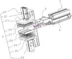
图1是本发明实施例中棉纤维样本拆分机构的结构示意图;Fig. 1 is the structural representation of the cotton fiber sample dismantling mechanism in the embodiment of the present invention;
图2是本发明实施例中样本盒的结构示意图;Fig. 2 is a schematic structural view of a sample box in an embodiment of the present invention;
图3是本发明实施例中夹持组件(未夹持状态)的结构示意图;Fig. 3 is a schematic structural view of the clamping assembly (unclamped state) in the embodiment of the present invention;
图4是本发明实施例中夹持组件(未夹持状态)的主视图;Fig. 4 is the front view of the clamping assembly (unclamped state) in the embodiment of the present invention;
图5时本发明实施例中基板与第一针孔板、第二针孔板连接示意图;Figure 5 is a schematic diagram of the connection between the substrate and the first pinhole plate and the second pinhole plate in the embodiment of the present invention;
图6是本发明实施例中夹持组件(夹持状态)的结构示意图;Fig. 6 is a schematic structural view of the clamping assembly (clamping state) in the embodiment of the present invention;
图7是本发明实施例中夹持组件(夹持状态)的剖视图;Fig. 7 is a cross-sectional view of the clamping assembly (clamping state) in the embodiment of the present invention;
图8是本发明实施例中棉纤维样本拆分机构未夹持时状态示意图;Fig. 8 is a schematic diagram of the state when the cotton fiber sample splitting mechanism is not clamped in the embodiment of the present invention;
图9是本发明实施例中棉纤维样本拆分机构夹持时状态示意图;Fig. 9 is a schematic diagram of the state when the cotton fiber sample splitting mechanism is clamped in the embodiment of the present invention;
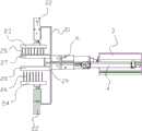
图10是本发明实施例中棉纤维样本拆分装置的结构示意图;Fig. 10 is a schematic structural view of a cotton fiber sample splitting device in an embodiment of the present invention;
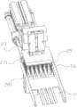
图11是本发明实施例中棉纤维样本拆分装置其中一侧的结构示意图;Fig. 11 is a schematic structural view of one side of the cotton fiber sample splitting device in an embodiment of the present invention;
图中标号:Labels in the figure:
1、样本盒;11、长条槽;1. Sample box; 11. Long slot;
2、夹持组件;21、基板;22、夹板气缸;23、第一夹板;24、第二夹板;25、第一针具;26、第二针具;27、第一针孔板;271、第一折边;28、第二针孔板;281、第二折边;29、限位板;2. Clamping assembly; 21. Base plate; 22. Plywood cylinder; 23. First plywood; 24. Second plywood; 25. First needle; 26. Second needle; 27. First pinhole plate; 271 , the first flanging; 28, the second pinhole plate; 281, the second flanging; 29, the limiting plate;
3、第一气缸;4、第二气缸;3. The first cylinder; 4. The second cylinder;
5、投送机构;51、第三气缸;52、竖直旋转机构;53、水平旋转机构;5. Delivery mechanism; 51. The third cylinder; 52. Vertical rotation mechanism; 53. Horizontal rotation mechanism;
6、开合气缸。6. Open and close the cylinder.
具体实施方式Detailed ways
为使本发明实施例的目的、技术方案和优点更加清楚,下面将结合本发明实施例,对本发明实施例中的技术方案进行清楚、完整地描述,显然,所描述的实施例是本发明一部分实施例,而不是全部的实施例。基于本发明中的实施例,本领域普通技术人员在没有作出创造性劳动前提下所获得的所有其他实施例,都属于本发明保护的范围。In order to make the purpose, technical solutions and advantages of the embodiments of the present invention clearer, the technical solutions in the embodiments of the present invention will be clearly and completely described below in conjunction with the embodiments of the present invention. Obviously, the described embodiments are part of the present invention Examples, not all examples. Based on the embodiments of the present invention, all other embodiments obtained by persons of ordinary skill in the art without creative efforts fall within the protection scope of the present invention.
实施例一:Embodiment one:
如图1所示,棉纤维样本拆分机构,包括样本盒1、两个镜像布置的夹持组件2,两个所述夹持组件2能够同时水平方向相对或背向运动的位于所述样本盒1的两侧;从而实现两个夹持组件2同时从样本盒1内夹持棉纤维样本后向两侧撕扯,使其分离为拥有自然撕扯口的两份待检长度和强度检测样本。图1中为了显示夹持组件2有不同的工作状态,故左侧夹持组件2为夹持状态,右侧夹持组件2为未夹持状态。As shown in Figure 1, the cotton fiber sample splitting mechanism includes a sample box 1, two
如图2所示,样本盒1是竖直截面为U型的壳体结构,其顶面和长度方向的两端为空,其底面包括多个沿长度方向开设的长条槽11,长条槽11为上下贯穿结构,但两端的长条槽11并未连通,两端的长条槽11也是对称布置,本实施例中,长条槽11总共十个,十个长条槽11均匀分布在样本盒1的两端,由其中一端可以看出,宽度方向上,两侧的长条槽11宽度大于位于中部的长条槽11;参考图6所示,这是由于两侧较宽的长条槽11需要容纳位于两侧最外侧的两排第一针具25,中部的长条槽11仅需容纳一排第一针具25。棉纤维样本与样本盒1在长度和宽度方向上相近即可,放置棉纤维样本时,保持样本均匀平铺在样本盒1内。As shown in Figure 2, the sample box 1 is a shell structure with a U-shaped vertical section, its top surface and two ends in the length direction are empty, and its bottom surface includes a plurality of
由于两侧的夹持组件2为相同结构,本实施例中以一个夹持组件2为例进行描述。如图3所示,所述夹持组件2包括基板21、夹板驱动件、第一夹板23、第二夹板24、第一针具25、第二针具26、第一针孔板27、第二针孔板28。其中,夹板驱动件为用于驱动第一夹板23以及第二夹板24上下运动的夹板气缸22,夹板驱动件也可以是其他能够实现上下方向往复运动的机构,如丝杆螺母机构、液压缸等。Since the clamping
基板21为两个,两个基板21上下沿水平面对称设置,如图4所示,两个基板21的右侧均连接一个90度翻转机构,该90度翻转机构为开合气缸6,两个开合气缸6能够实现两个基板21张开与闭合。工作开始初期,开合气缸6动作,将位于上部的基板21顺时针旋转,位于下部的基板21逆时针旋转,实现夹持组件2像虎口一样张开,然后前进到夹持位的时候再将夹持组件2合起来,如图4中两个基板21呈平行状态。There are two
如图4所述,同时参考图5,位于上面的基板21的顶端和位于下面的基板21的底端均呈U型折弯,折弯后的侧面用于安装夹板气缸22,两个夹板气缸22沿水平面镜像布置,夹板气缸22通过螺栓等方式连接在基板21上。位于上部的夹板气缸22的伸缩端与第一夹板23连接,第一夹板23的底面连接多个第一针具25,位于下部的夹板气缸22的伸缩端与第二夹板24连接,第二夹板24的顶面连接多个第二针具26。As shown in Figure 4, referring to Figure 5 at the same time, the top of the
本实施例中,第一针具25、第二针具26均呈矩阵排列,本实施例中,第一针具25呈7*8的矩阵形式,第一针具25呈7*7的矩阵形式,当然,具体设置的排数和列数可以根据实际需要更换,以及相邻第一针具25、相邻第二针具26之间的距离可以根据实际需要设置,第一针具25与第二针具26排布无需过密。In this embodiment, the
第一针具25与第二针具26均为圆柱形针状结构,端部可以是尖端,为使针更容易扎入样本,在保证强度的前提下针具的端部应尽量的尖。Both the
所述第一针具25在所述第二夹板24上的竖直方向投影与所述第二针具26不重合;即:参考图4或图7所示,第一针具25的竖直轴线与第二针具26的竖直轴线不重合,二者呈交错布置,为了避免第一针具25与第二针具26夹持时抵接在一起,降低对棉纤维的压实,压实交错后整体上摩擦力更大导致更难撕扯开,也更容易产生断裂的纤维,改变其内部结构,获得误差较大的检测结果。The vertical projection of the
其中,如图7所示,所述第一针具25长度小于第二针具26的长度,这样做的目的是:在采用夹持组件2夹持棉纤维时,为了避免棉纤维因过于贴近样本盒1而造成挤压集中,进而产生影响撕扯的摩擦力,因此,第一针具25较短,使得第一针具25与第二针具26互相靠近、交错至夹持状态时棉纤维可以被第二针具26顶高一点,减少棉纤维与样本盒1的挤压。同时也可以避免棉纤维被压,导致其内部纤维交错从而改变了其内部结构。Wherein, as shown in Figure 7, the length of the
如图3所示,同时参考图6所示,第一针孔板27与第二针孔板28水平连接基板21的中部,第一针孔板27与第二针孔板28上下间隔布置,第一针孔板27上包括多个与第一针具25位置对应的针孔,针孔的内径大于第一针具25的外径,即第一针具25在上下方向运动时,能够穿过第一针孔板27上的针孔;第二针孔板28上包括多个与第二针具26位置对应的针孔,针孔的内径大于第二针具26的外径,即第二针具26在上下方向运动时,能够穿过第二针孔板28上的针孔。As shown in FIG. 3 and referring to FIG. 6 at the same time, the
第一针具25与第二针具26在水平方向上与长条槽11的位置对应,即:包括第一针具25与第二针具26与长条槽11的位置对应,当然在本实施例中,第一针具25由于较短且由于第一针孔板27的限位,第一针具25一般不会插入到长条槽11内,仅第二针具26能够由样本盒1的底部穿过长条槽11。The first pins 25 and the
如图5所示,所述第一针孔板27沿所述样本盒1长度方向的两侧边向下折弯形成第一折边271,所述第二针孔板28的沿所述样本盒1长度方向的两侧边向上折弯形成第二折边281。第一折边271与第二折边281可以起到托起棉纤维的作用,减少棉纤维与样本盒1的挤压。也是避免棉纤维被压,压实交错后整体上摩擦力更大导致更难撕扯开,也更容易产生断裂的纤维,再者可以在运输过程中辅助最外侧的第一针具25、第二针具26固定棉纤维样本。As shown in FIG. 5 , the
如图6所示,需要说明的是:图6是夹持组件2的夹持状态,图中为了看清第一针具25与第二针具26在夹持时的状态,故没有放置棉纤维样本实物;所述第一折边271的外侧具有一排所述第一针具25,所述第二折边281的外侧具有一排所述第二针具26。位于最外侧的第一针具25与第二针具26,一方面为了尽量平均地扎住棉纤维样本,也避免最外沿的棉花向两边松开,另一方面可以在撕扯完成后的运输过程中,固定样本。As shown in Figure 6, it should be noted that: Figure 6 is the clamping state of the clamping
所述第一针具25的最宽距离处以及所述第二针具26的最宽距离处小于所述样本盒1内的宽度;保证夹持时,如图6、图7所示,第一夹板23、第二夹板24、第一针具25、第二针具26、第一针孔板27、第二针孔板28均能够沿样本盒1的长条槽11水平运动。图6中最左侧的两列第一针具25和最左侧的两列第二针具26以及左侧的第一折边271和左侧的第二折边281竖直方向的投影与最左侧的长条槽11重合;最右侧的两列第一针具25和最右侧的两列第二针具26以及右侧的第一折边271和右侧的第二折边281竖直方向的投影与最右侧的长条槽11重合;剩下的中间三列第一针具25和剩下的中间三列第二针具26竖直方向的投影与中部的三个长条槽11重合。The widest distance of the
棉纤维样本拆分机构还包括两个第一驱动件,在本实施例中,第一驱动件为第一气缸3,两个所述第一气缸3的伸缩端分别连接两个夹持组件2。如图1所示,左侧的第一气缸3与左侧的夹持组件2连接,右侧的第一气缸3与右侧的夹持组件2连接。具体的,第一气缸3伸缩端通过凸型框架与夹持组件2连接。The cotton fiber sample splitting mechanism also includes two first driving parts. In this embodiment, the first driving part is the
如图10所示,棉纤维样本拆分机构还包括四个第二驱动件,本实施例中,第二驱动件为第二气缸4,每个夹持组件2配置两个第二气缸4,凸型框架的两侧开设圆孔,第二气缸4穿过该圆孔并与之固定连接,第一气缸3、两个第二气缸4、凸型框架和夹持组件2合为一个整体,相对静止;以实现第二气缸4的伸缩带动凸型框架移动,继而实现夹持组件2的移动。同时参考图3所示,第二气缸4的伸缩端连接一个长板,长板的末端连接限位板29,其中两个基板21之间具有间隙,长板可以由两个基板21之间的间隙穿过,所述限位板29位于所述第一夹板23与所述第二夹板24之间。限位板29在夹持棉纤维样本时可以辅助固定棉纤维样本,在完成撕扯并已经移动到检测设备投入口时,第一夹板23与第二夹板24松开后,这时样品位于第一针孔板27与第二针孔板28之间,此时第二气缸4伸长,将样本推出。本实施例采用限位板29推出夹持组件2,继而进入长度检测机构和强度检测机构,能够保障样本准确送入检测机构,解决现有送入位置不准确的缺点。As shown in FIG. 10 , the cotton fiber sample splitting mechanism also includes four second drive members. In this embodiment, the second drive members are
第一驱动件与第二驱动件还可以是液压缸、丝杠螺母等能够实现往复运动的机构。The first driving member and the second driving member may also be mechanisms capable of reciprocating motion, such as a hydraulic cylinder, a screw nut, or the like.
如图3所示,限位板29为矩形板,限位板29的长度均大于第一针孔板27、第二针孔板28,因此,限位板29的四个角处,均切除一个小的矩形缺口,使得限位板29的四个角处与第一折边271以及第二折边281卡接。As shown in Figure 3, the
本实施例的工作过程:The working process of this embodiment:
如图8所示,初始状态(未夹持状态)时,两个夹持组件2的第一夹板23与第二夹板24处于远离状态,并位于样本盒1的两端,将棉花原样(图中未示出)置于样本盒1内,棉花原样尽量均匀分布,棉花原样不需要伸出样本盒1两端;As shown in Figure 8, in the initial state (unclamped state), the
工作启动,两个夹持组件2由两侧的第一气缸3伸长,相对运动逐渐靠近,至设定位置,设定位置可以由设定第一气缸3的伸缩量实现,如图9所示,第一夹板23在夹板气缸22以及第二夹板24在夹板气缸22带动下,第一针具25与第二针具26穿过第一针孔板27以及第二针孔板28,第一针具25与第二针具26咬合,夹持住各自一端的棉花原样。夹持完成后,两个夹持组件2由第一气缸3缩回的带动下相互远离至初始位置,从而撕扯棉花原样使其分离为两份待测样本。When the work is started, the two
现有技术中通过裁剪、压住拉扯状态下获得的棉纤维样本内部纤维遭到破坏,无法得到准确的检测数据,本实施例通过两组夹持组件2对棉花原样进行两端撕扯,获得自然撕扯下的棉纤维样本,可以实现无损拆棉,提高检测的准确性。且本实施例中,通过相同的两组夹持组件2进行撕扯,两端作用力一致,从而获得两份质量相同的待测样本,减少出现出现大样本或小样本的情况,无需多次检测,提高检测效率。In the prior art, the internal fibers of the cotton fiber sample obtained by cutting, pressing and pulling are destroyed, and accurate detection data cannot be obtained. The torn cotton fiber sample can realize non-destructive cotton removal and improve the accuracy of detection. Moreover, in this embodiment, the same two sets of clamping
实施例二:Embodiment two:
如图10、图11所示,本实施例公开采用上述实施例棉纤维样本拆分机构的装置,还包括两组镜像布置的投送机构5,每组所述投送机构5均包括第三气缸51、竖直旋转机构52、水平旋转机构53,所述第三气缸51的伸缩端连接所述竖直旋转机构52的一端,所述竖直旋转机构52连接所述水平旋转机构53,所述水平旋转机构53连接第一气缸3。As shown in Fig. 10 and Fig. 11, the present embodiment discloses the device adopting the cotton fiber sample dismantling mechanism of the above-mentioned embodiment, and also includes two sets of
竖直旋转机构52即可以实现其活动端竖直方向上旋转的机构,可以是90度旋转气缸,水平旋转机构53即实现其活动端水平方向上旋转的机构,可以是90度旋转气缸。90度旋转气缸可以是现有技术中。The
夹持组件2在第一气缸3、水平旋转机构53、竖直旋转机构52组成串联系统作用下,能够实现多个角度、高度方向上的运输,将撕扯好的两份棉纤维样本通过姿态变化,精准送入检测仪器前,后夹板气缸22缩回,第一针具25、第二针具26收回,不再对棉纤维样本进行夹持,棉纤维样本至于第二针孔板28上,此时通过第二气缸4伸长,通过限位板29将样本推出至检测仪器。完成后,第二气缸4缩回。Under the action of the series system composed of the
投送机构5也可以由现有技术中的机械手代替,但要求该机械手能够实现的就是通过一套可灵活改变姿态的机构来连接“拆分”-“运输”-“投送”-“复位”的工作流程。The
整个装置可以实现自动化样本拆分、运送,提高检测效率。The whole device can realize automatic sample splitting and transportation, and improve detection efficiency.
以上实施例仅用以说明本发明的技术方案,而非对其限制;尽管参照前述实施例对本发明进行了详细的说明,本领域的普通技术人员应当理解:其依然可以对前述各实施例所记载的技术方案进行修改,或者对其中部分技术特征进行等同替换;而这些修改或者替换,并不使相应技术方案的本质脱离本发明各实施例技术方案的精神和范围。The above embodiments are only used to illustrate the technical solutions of the present invention, rather than to limit them; although the present invention has been described in detail with reference to the foregoing embodiments, those of ordinary skill in the art should understand that: it can still be described in the foregoing embodiments Modifications are made to the recorded technical solutions, or equivalent replacements are made to some of the technical features; and these modifications or replacements do not make the essence of the corresponding technical solutions deviate from the spirit and scope of the technical solutions of the embodiments of the present invention.
Claims (10)
Priority Applications (1)
| Application Number | Priority Date | Filing Date | Title |
|---|---|---|---|
| CN202310159878.9ACN115824753B (en) | 2023-02-24 | 2023-02-24 | Cotton fiber sample splitting mechanism and device |
Applications Claiming Priority (1)
| Application Number | Priority Date | Filing Date | Title |
|---|---|---|---|
| CN202310159878.9ACN115824753B (en) | 2023-02-24 | 2023-02-24 | Cotton fiber sample splitting mechanism and device |
Publications (2)
| Publication Number | Publication Date |
|---|---|
| CN115824753Atrue CN115824753A (en) | 2023-03-21 |
| CN115824753B CN115824753B (en) | 2023-05-09 |
Family
ID=85522259
Family Applications (1)
| Application Number | Title | Priority Date | Filing Date |
|---|---|---|---|
| CN202310159878.9AActiveCN115824753B (en) | 2023-02-24 | 2023-02-24 | Cotton fiber sample splitting mechanism and device |
Country Status (1)
| Country | Link |
|---|---|
| CN (1) | CN115824753B (en) |
Cited By (1)
| Publication number | Priority date | Publication date | Assignee | Title |
|---|---|---|---|---|
| CN116296698A (en)* | 2023-05-19 | 2023-06-23 | 中国科学技术大学 | Cotton fiber shaping and splitting equipment |
Citations (11)
| Publication number | Priority date | Publication date | Assignee | Title |
|---|---|---|---|---|
| US5014394A (en)* | 1989-04-10 | 1991-05-14 | Siegfried Peyer Ag | Method and apparatus for making representative samples of textile fibers |
| US5178020A (en)* | 1991-09-11 | 1993-01-12 | Motion Control, Inc. | Fiber sampler |
| CZ20033134A3 (en)* | 2003-11-18 | 2005-07-13 | Rieter Cz A. S. | Process for producing spinnable vegetable fibers and products made therefrom |
| CN110132669A (en)* | 2019-04-29 | 2019-08-16 | 河北科技大学 | Cotton fiber sample preparation device |
| CN209480702U (en)* | 2018-10-16 | 2019-10-11 | 深圳市众创立科技有限公司 | Core item clamps conveyer and spectacle frame process equipment |
| CN111366396A (en)* | 2020-03-20 | 2020-07-03 | 北京空间飞行器总体设计部 | A small celestial body integrated sampler with grinding and clamping functions |
| CN111452113A (en)* | 2019-01-18 | 2020-07-28 | 天津工业大学 | Textile chopping method and textile chopping device applying same |
| CN113358443A (en)* | 2021-07-06 | 2021-09-07 | 中国科学技术大学 | Fixed-mass cotton fiber sample production device |
| CN114047042A (en)* | 2021-11-09 | 2022-02-15 | 中国科学技术大学 | Fibrous sample splitting equipment |
| CN114646751A (en)* | 2022-05-19 | 2022-06-21 | 中国科学技术大学 | A kind of cotton fiber automatic detection equipment |
| CN115537976A (en)* | 2022-11-29 | 2022-12-30 | 中国科学技术大学 | A non-damaging automatic cotton removal equipment |
- 2023
- 2023-02-24CNCN202310159878.9Apatent/CN115824753B/enactiveActive
Patent Citations (11)
| Publication number | Priority date | Publication date | Assignee | Title |
|---|---|---|---|---|
| US5014394A (en)* | 1989-04-10 | 1991-05-14 | Siegfried Peyer Ag | Method and apparatus for making representative samples of textile fibers |
| US5178020A (en)* | 1991-09-11 | 1993-01-12 | Motion Control, Inc. | Fiber sampler |
| CZ20033134A3 (en)* | 2003-11-18 | 2005-07-13 | Rieter Cz A. S. | Process for producing spinnable vegetable fibers and products made therefrom |
| CN209480702U (en)* | 2018-10-16 | 2019-10-11 | 深圳市众创立科技有限公司 | Core item clamps conveyer and spectacle frame process equipment |
| CN111452113A (en)* | 2019-01-18 | 2020-07-28 | 天津工业大学 | Textile chopping method and textile chopping device applying same |
| CN110132669A (en)* | 2019-04-29 | 2019-08-16 | 河北科技大学 | Cotton fiber sample preparation device |
| CN111366396A (en)* | 2020-03-20 | 2020-07-03 | 北京空间飞行器总体设计部 | A small celestial body integrated sampler with grinding and clamping functions |
| CN113358443A (en)* | 2021-07-06 | 2021-09-07 | 中国科学技术大学 | Fixed-mass cotton fiber sample production device |
| CN114047042A (en)* | 2021-11-09 | 2022-02-15 | 中国科学技术大学 | Fibrous sample splitting equipment |
| CN114646751A (en)* | 2022-05-19 | 2022-06-21 | 中国科学技术大学 | A kind of cotton fiber automatic detection equipment |
| CN115537976A (en)* | 2022-11-29 | 2022-12-30 | 中国科学技术大学 | A non-damaging automatic cotton removal equipment |
Cited By (2)
| Publication number | Priority date | Publication date | Assignee | Title |
|---|---|---|---|---|
| CN116296698A (en)* | 2023-05-19 | 2023-06-23 | 中国科学技术大学 | Cotton fiber shaping and splitting equipment |
| CN116296698B (en)* | 2023-05-19 | 2023-10-20 | 中国科学技术大学 | Cotton fiber shaping and splitting equipment |
Also Published As
| Publication number | Publication date |
|---|---|
| CN115824753B (en) | 2023-05-09 |
Similar Documents
| Publication | Publication Date | Title |
|---|---|---|
| CN115824753B (en) | Cotton fiber sample splitting mechanism and device | |
| EP3611497B1 (en) | Inspection apparatus for inspecting a cable tip of a cable and method for cleaning the mirror of an inspection apparatus | |
| CN207632081U (en) | A kind of test tube captures barcode scanning mechanism automatically | |
| CN219038651U (en) | Large-capacity fiber tensile testing device | |
| DE10304174A1 (en) | Device and method for wafer back inspection | |
| CN114047042B (en) | A fibrous sample splitting device | |
| CN214472293U (en) | Clamping device of metal tensile testing machine | |
| CN111141608B (en) | Miniature uniaxial stretching device based on automatic sample changing and in-situ observation test method | |
| DE112008003262T5 (en) | Test device and test method for substrate surfaces | |
| CN114509663A (en) | Circuit board detection equipment of intelligent power supply chip | |
| CN219039095U (en) | Fiber sample loading device | |
| WO2025092625A1 (en) | Positioning jig and test apparatus | |
| CN118641338B (en) | A corrugated paper detection device | |
| CN119666538A (en) | A casting strength testing device | |
| CN112829331B (en) | Detection mechanism for scissor feet | |
| CN211453135U (en) | Tension tester | |
| CN211652352U (en) | Miniature uniaxial stretching device based on automatic sample changing | |
| US5178020A (en) | Fiber sampler | |
| CN118654986A (en) | A testing device for rubber products | |
| JP2013213709A (en) | Material testing machine | |
| CN214279902U (en) | Sample pedestal with positioning and clamping functions for scanning electron microscope | |
| CN214354331U (en) | Detection mechanism for scissor feet | |
| CN116907984A (en) | Physical and chemical property test platform for natural fiber composite plastic | |
| JP4563080B2 (en) | Substrate holding mechanism for inspection | |
| CN223413227U (en) | A test paper transmission fork plate structure |
Legal Events
| Date | Code | Title | Description |
|---|---|---|---|
| PB01 | Publication | ||
| PB01 | Publication | ||
| SE01 | Entry into force of request for substantive examination | ||
| SE01 | Entry into force of request for substantive examination | ||
| GR01 | Patent grant | ||
| GR01 | Patent grant |