CN115808130A - Battery cell winding calibration method and equipment - Google Patents
Battery cell winding calibration method and equipmentDownload PDFInfo
- Publication number
- CN115808130A CN115808130ACN202111197958.0ACN202111197958ACN115808130ACN 115808130 ACN115808130 ACN 115808130ACN 202111197958 ACN202111197958 ACN 202111197958ACN 115808130 ACN115808130 ACN 115808130A
- Authority
- CN
- China
- Prior art keywords
- distance
- winding
- reference line
- edge
- wound
- Prior art date
- Legal status (The legal status is an assumption and is not a legal conclusion. Google has not performed a legal analysis and makes no representation as to the accuracy of the status listed.)
- Granted
Links
Images


Classifications
- H—ELECTRICITY
- H01—ELECTRIC ELEMENTS
- H01M—PROCESSES OR MEANS, e.g. BATTERIES, FOR THE DIRECT CONVERSION OF CHEMICAL ENERGY INTO ELECTRICAL ENERGY
- H01M10/00—Secondary cells; Manufacture thereof
- H01M10/04—Construction or manufacture in general
- G—PHYSICS
- G01—MEASURING; TESTING
- G01B—MEASURING LENGTH, THICKNESS OR SIMILAR LINEAR DIMENSIONS; MEASURING ANGLES; MEASURING AREAS; MEASURING IRREGULARITIES OF SURFACES OR CONTOURS
- G01B11/00—Measuring arrangements characterised by the use of optical techniques
- G01B11/14—Measuring arrangements characterised by the use of optical techniques for measuring distance or clearance between spaced objects or spaced apertures
- G—PHYSICS
- G01—MEASURING; TESTING
- G01B—MEASURING LENGTH, THICKNESS OR SIMILAR LINEAR DIMENSIONS; MEASURING ANGLES; MEASURING AREAS; MEASURING IRREGULARITIES OF SURFACES OR CONTOURS
- G01B11/00—Measuring arrangements characterised by the use of optical techniques
- G01B11/02—Measuring arrangements characterised by the use of optical techniques for measuring length, width or thickness
- G01B11/028—Measuring arrangements characterised by the use of optical techniques for measuring length, width or thickness by measuring lateral position of a boundary of the object
- H—ELECTRICITY
- H01—ELECTRIC ELEMENTS
- H01M—PROCESSES OR MEANS, e.g. BATTERIES, FOR THE DIRECT CONVERSION OF CHEMICAL ENERGY INTO ELECTRICAL ENERGY
- H01M10/00—Secondary cells; Manufacture thereof
- H01M10/04—Construction or manufacture in general
- H01M10/0404—Machines for assembling batteries
- H01M10/0409—Machines for assembling batteries for cells with wound electrodes
- H—ELECTRICITY
- H01—ELECTRIC ELEMENTS
- H01M—PROCESSES OR MEANS, e.g. BATTERIES, FOR THE DIRECT CONVERSION OF CHEMICAL ENERGY INTO ELECTRICAL ENERGY
- H01M10/00—Secondary cells; Manufacture thereof
- H01M10/04—Construction or manufacture in general
- H01M10/0431—Cells with wound or folded electrodes
- H—ELECTRICITY
- H01—ELECTRIC ELEMENTS
- H01M—PROCESSES OR MEANS, e.g. BATTERIES, FOR THE DIRECT CONVERSION OF CHEMICAL ENERGY INTO ELECTRICAL ENERGY
- H01M10/00—Secondary cells; Manufacture thereof
- H01M10/05—Accumulators with non-aqueous electrolyte
- H01M10/058—Construction or manufacture
- H01M10/0587—Construction or manufacture of accumulators having only wound construction elements, i.e. wound positive electrodes, wound negative electrodes and wound separators
- Y—GENERAL TAGGING OF NEW TECHNOLOGICAL DEVELOPMENTS; GENERAL TAGGING OF CROSS-SECTIONAL TECHNOLOGIES SPANNING OVER SEVERAL SECTIONS OF THE IPC; TECHNICAL SUBJECTS COVERED BY FORMER USPC CROSS-REFERENCE ART COLLECTIONS [XRACs] AND DIGESTS
- Y02—TECHNOLOGIES OR APPLICATIONS FOR MITIGATION OR ADAPTATION AGAINST CLIMATE CHANGE
- Y02E—REDUCTION OF GREENHOUSE GAS [GHG] EMISSIONS, RELATED TO ENERGY GENERATION, TRANSMISSION OR DISTRIBUTION
- Y02E60/00—Enabling technologies; Technologies with a potential or indirect contribution to GHG emissions mitigation
- Y02E60/10—Energy storage using batteries
- Y—GENERAL TAGGING OF NEW TECHNOLOGICAL DEVELOPMENTS; GENERAL TAGGING OF CROSS-SECTIONAL TECHNOLOGIES SPANNING OVER SEVERAL SECTIONS OF THE IPC; TECHNICAL SUBJECTS COVERED BY FORMER USPC CROSS-REFERENCE ART COLLECTIONS [XRACs] AND DIGESTS
- Y02—TECHNOLOGIES OR APPLICATIONS FOR MITIGATION OR ADAPTATION AGAINST CLIMATE CHANGE
- Y02P—CLIMATE CHANGE MITIGATION TECHNOLOGIES IN THE PRODUCTION OR PROCESSING OF GOODS
- Y02P70/00—Climate change mitigation technologies in the production process for final industrial or consumer products
- Y02P70/50—Manufacturing or production processes characterised by the final manufactured product
Landscapes
- Engineering & Computer Science (AREA)
- Manufacturing & Machinery (AREA)
- Chemical & Material Sciences (AREA)
- Chemical Kinetics & Catalysis (AREA)
- Electrochemistry (AREA)
- General Chemical & Material Sciences (AREA)
- Physics & Mathematics (AREA)
- General Physics & Mathematics (AREA)
- Length Measuring Devices By Optical Means (AREA)
- Secondary Cells (AREA)
Abstract
Translated fromChinese
Description
Translated fromChinese技术领域technical field
本发明实施例涉及电池技术领域,具体涉及一种电芯卷绕校准方法及设备。Embodiments of the present invention relate to the technical field of batteries, and in particular to a battery winding calibration method and equipment.
背景技术Background technique
现有电池的电芯可以通过层叠或卷绕形成,卷绕电芯包括极片和隔膜,隔膜主要用于阻隔极片,避免极片之间发生接触而造成短路,因此卷绕电芯在卷绕过程中需要保证隔膜与极片边缘之间的距离满足要求。The cells of existing batteries can be formed by stacking or winding. The wound cells include pole pieces and separators. The diaphragm is mainly used to block the pole pieces and avoid short circuits caused by contact between pole pieces. During the winding process, it is necessary to ensure that the distance between the diaphragm and the edge of the pole piece meets the requirements.
本申请发明人在研究中发现,目前电芯在卷绕过程中,通常设定好图像采集装置的焦距后,通过图像采集装置对电芯表面进行成像,实现对极片与隔膜边缘之间距离的检测,但是随着电芯的卷绕,其厚度相应增加,使得图像采集装置设定的焦距与图像采集装置至电芯的实际距离之间发生偏差,造成图像模糊、虚化等问题,从而出现检测出错的情况。The inventors of the present application found in their research that at present, during the winding process of the electric core, after setting the focal length of the image acquisition device, the image acquisition device is used to image the surface of the electric core to realize the distance between the pole piece and the edge of the diaphragm. However, with the winding of the battery core, its thickness increases accordingly, which causes a deviation between the focal length set by the image acquisition device and the actual distance from the image acquisition device to the battery core, resulting in problems such as blurred and blurred images, thus A detection error has occurred.
发明内容Contents of the invention
鉴于上述问题,本发明实施例提供一种电芯卷绕校准方法及设备,以提高对电芯边缘位置检测的准确性,实现电芯卷绕校准时的精确性。In view of the above problems, the embodiments of the present invention provide a cell winding calibration method and equipment, so as to improve the accuracy of detecting the edge position of the cell and realize the accuracy of cell winding calibration.
根据本发明实施例的一个方面,提供一种电芯卷绕校准方法,包括:获取第一基准线与第二基准线之间的第一基准距离,第一基准线和第二基准线为在卷绕基材上形成的相互平行的标识线,第一基准距离在电芯卷绕过程中保持不变;获取第一基准距离所包含的基准像素数,根据第一基准距离和第一基准距离所包含的基准像素数,确定单个像素所对应的实际距离;获取卷绕基材边缘与第一基准线或第二基准线之间距离所包含的实际像素数,根据卷绕基材边缘与第一基准线或第二基准线之间距离所包含的实际像素数和单个像素所对应的实际距离,确定卷绕基材边缘的实时位置信息;根据卷绕基材边缘的实时位置信息对卷绕基材进行校准。According to an aspect of an embodiment of the present invention, a battery winding calibration method is provided, including: acquiring a first reference distance between a first reference line and a second reference line, the first reference line and the second reference line being For the marking lines parallel to each other formed on the winding substrate, the first reference distance remains unchanged during the winding process of the cell; the number of reference pixels included in the first reference distance is obtained, and according to the first reference distance and the first reference distance The included number of reference pixels determines the actual distance corresponding to a single pixel; obtains the actual number of pixels included in the distance between the edge of the winding substrate and the first reference line or the second reference line, according to the distance between the edge of the winding substrate and the second reference line The actual number of pixels contained in the distance between a reference line or the second reference line and the actual distance corresponding to a single pixel determine the real-time position information of the edge of the winding substrate; according to the real-time position information of the edge of the winding substrate The base material is calibrated.
本申请根据获取的第一基准线与第二基准线之间的第一基准距离以及第一基准距离所包含的基准像素数,确定单个像素所对应的实际距离,由于第一基准线和第二基准线为在卷绕基材上形成的相互平行的标识线,并且第一基准距离在电芯卷绕过程中保持不变,因此即使卷绕基材随着卷绕过程厚度增加,物距发生变化,采集的图像分辨率随之改变,依然可以准确无误地确定单个像素所对应的实际距离。由于第一基准线和第二基准线为在卷绕基材上形成的相互平行的标识线,因此第一基准线和第二基准线在成像中更加容易识别,并且为了避免由于图像虚化以及隔膜与极片边缘之间距离过小而造成隔膜与极片边缘之间距离较难识别清楚,通过读取卷绕基材中隔膜及极片边缘至第一基准线或第二基准线之间距离所包含的像素数,并结合单个像素所对应的实际距离,以准确无误地确定卷绕基材边缘的实时位置信息,进而对卷绕基材的边缘准确有效地进行校准,保证卷绕基材卷绕的合格率。The present application determines the actual distance corresponding to a single pixel based on the obtained first reference distance between the first reference line and the second reference line and the number of reference pixels included in the first reference distance. Since the first reference line and the second reference line The reference line is the marking line parallel to each other formed on the winding substrate, and the first reference distance remains unchanged during the winding process of the battery core, so even if the thickness of the winding substrate increases with the winding process, the object distance will The resolution of the collected image changes accordingly, and the actual distance corresponding to a single pixel can still be accurately determined. Since the first reference line and the second reference line are marking lines parallel to each other formed on the winding substrate, the first reference line and the second reference line are easier to identify in imaging, and in order to avoid image blurring and The distance between the diaphragm and the edge of the pole piece is too small, which makes it difficult to identify the distance between the diaphragm and the edge of the pole piece. By reading the distance between the diaphragm and the edge of the pole piece in the winding substrate and the first reference line or the second reference line The number of pixels included in the distance, combined with the actual distance corresponding to a single pixel, can accurately determine the real-time position information of the edge of the winding substrate, and then accurately and effectively calibrate the edge of the winding substrate to ensure that the winding substrate The qualified rate of material winding.
在一种可选的方式中,第一基准距离所包含的基准像素数至少为一个。第一基准距离所包含的基准像素数至少为一个是指在图像采集单元对卷绕基材进行采集的图像中,第一基准线和第二基准线之间的距离至少为一个像素块,目的是保证可以准确地得出单个像素所对应的实际距离,避免由于图像中第一基准距离过小造成第一基准距离所包含的基准像素数获取失败或出错。In an optional manner, the number of reference pixels included in the first reference distance is at least one. The number of reference pixels included in the first reference distance is at least one, which means that in the image collected by the image acquisition unit on the winding substrate, the distance between the first reference line and the second reference line is at least one pixel block. It is to ensure that the actual distance corresponding to a single pixel can be accurately obtained, and to avoid failure or error in obtaining the number of reference pixels contained in the first reference distance due to too small first reference distance in the image.
在一种可选的方式中,卷绕基材包括已经完成卷绕操作的已卷绕层和即将进行卷绕操作的待卷绕层;第一基准线和第二基准线为在已卷绕层外侧面和待卷绕层内侧面形成的相互平行的标识线。卷绕基材一般依次分为正极极片、第一隔膜、负极极片和第二隔膜,隔膜的表面积要比正积极片和负极极片的表面积大,以保证隔膜将正积极片和负极极片完全隔离,避免极片间发生接触造成短路风险。隔膜一般具有一定的透明性,而极片不具有透明性,因此,考虑到从卷绕基材的一面采集图像时,仅能看到一个极片和一个隔膜的边缘,远离图像采集单元的极片和隔膜无法采集到其边缘,本申请通过在已卷绕层外侧面和待卷绕层内侧面均形成第一基准线和第二基准线,并一次同时对已卷绕层外侧面和待卷绕层内侧面进行图像采集,分别实现对两个极片和两个隔膜边缘的图像采集和识别。In an optional manner, the winding substrate includes a wound layer that has completed the winding operation and a layer to be wound that is about to undergo the winding operation; the first reference line and the second reference line are Marking lines parallel to each other formed by the outer side of the layer and the inner side of the layer to be wound. The winding base material is generally divided into positive electrode sheet, first separator, negative electrode sheet and second separator in turn. The surface area of the separator is larger than the surface area of the positive electrode sheet and the negative electrode sheet to ensure that the separator will connect the positive electrode sheet and the negative electrode sheet. The pole pieces are completely isolated to avoid the risk of short circuit caused by contact between pole pieces. The diaphragm generally has a certain degree of transparency, while the pole piece does not have transparency. Therefore, considering that when collecting images from one side of the winding substrate, only the edge of one pole piece and one diaphragm can be seen, and the pole piece away from the image acquisition unit The edge of the sheet and the diaphragm cannot be collected. This application forms the first reference line and the second reference line on the outer side of the wound layer and the inner side of the layer to be wound, and simultaneously measures the outer side of the wound layer and the inner side of the layer to be wound. Image acquisition is performed on the inner side of the winding layer to realize image acquisition and recognition of the edges of the two pole pieces and the two diaphragms respectively.
在一种可选的方式中,获取第一基准距离所包含的基准像素数,根据第一基准距离和第一基准距离所包含的基准像素数,确定单个像素所对应的实际距离,包括:在待卷绕层内侧面获取第一基准距离所包含的第一基准像素数,根据第一基准距离和第一基准像素数确定单个像素所对应的第一实际距离;在已卷绕层外侧面获取第一基准距离所包含的第二基准像素数,根据第一基准距离和第二基准像素数确定单个像素所对应的第二实际距离。通过分别对待卷绕层内侧面和已卷绕层外侧面进行图像采集获得待卷绕层内侧面的图像和已卷绕层外侧面的图像,在待卷绕层内侧面图像和已卷绕层外侧面图像中获取第一基准距离所包含的第一基准像素数和第二基准像素数,根据第一基准距离和第一基准像素数、第二基准像素数,确定两个图像中单个像素所对应的第一实际距离和第二实际距离,可以有效避免由于图像采集单元景深较小而造成卷绕基材的成像中部分表面模糊,对待卷绕层内侧面和已卷绕层外侧面分开进行图像采集,保证待卷绕层内侧面和已卷绕层外侧面的成像均具有良好的分辨率,图像清晰,有利于提升对卷绕基材边缘位置检测的精准度。In an optional manner, the number of reference pixels included in the first reference distance is obtained, and the actual distance corresponding to a single pixel is determined according to the first reference distance and the number of reference pixels included in the first reference distance, including: The first reference pixel number contained in the first reference distance is acquired on the inner side of the layer to be wound, and the first actual distance corresponding to a single pixel is determined according to the first reference distance and the first reference pixel number; The second reference pixel number included in the first reference distance, and the second actual distance corresponding to a single pixel is determined according to the first reference distance and the second reference pixel number. The image of the inner side of the layer to be wound and the image of the outer side of the wound layer are obtained by image acquisition respectively on the inner side of the layer to be wound and the outer side of the wound layer. Obtain the first reference pixel number and the second reference pixel number contained in the first reference distance in the outer side image, and determine the number of single pixels in the two images according to the first reference distance, the first reference pixel number, and the second reference pixel number. The corresponding first actual distance and second actual distance can effectively avoid part of the surface blurring in the imaging of the winding substrate due to the small depth of field of the image acquisition unit, and separate the inner side of the to-be-wound layer from the outer side of the wound layer. Image acquisition ensures that the imaging of the inner side of the layer to be wound and the outer side of the wound layer has good resolution and clear images, which is conducive to improving the accuracy of edge position detection of the wound substrate.
在一种可选的方式中,获取卷绕基材边缘与第一基准线或第二基准线之间距离所包含的实际像素数,包括:分别获取已卷绕层外侧面的边缘和待卷绕层内侧面的边缘与第一基准线或第二基准线之间距离所包含的实际像素数。分别获取已卷绕层外侧面的边缘和待卷绕层内侧面的边缘与第一基准线或第二基准线之间距离所包含的实际像素数,进而实现对卷绕基材中两个极片和两个隔膜边缘的位置信息的精确检测。In an optional manner, obtaining the actual number of pixels contained in the distance between the edge of the wound substrate and the first reference line or the second reference line includes: respectively obtaining the edge of the outer surface of the wound layer and the The actual number of pixels contained in the distance between the edge of the inner side of the wrap layer and the first or second baseline. The actual number of pixels included in the distance between the edge of the outer side of the wound layer and the inner side of the layer to be wound and the first reference line or the second reference line is obtained respectively, and then the two poles in the wound substrate are realized. Precise detection of positional information of the sheet and the two diaphragm edges.
在一种可选的方式中,方法进一步包括:获取第三基准线与第四基准线之间的第二基准距离,第三基准线和第四基准线位于卷绕基材上与第一基准线和第二基准线相对的一端,为相互平行的标识线,第二基准距离在电芯卷绕过程中保持不变。通过在卷绕基材一端的表面形成第一基准线和第二基准线,另一端形成第三基准线和第四基准线,从而保证当需要对卷绕基材两端的边缘分别成像时,每个图像中均具有双基准线,进而保证检测的准确性,并且可以减小图像采集单元的取景成像的面积,优化采集的图像,提高检测的精度。In an optional manner, the method further includes: acquiring a second reference distance between the third reference line and the fourth reference line, where the third reference line and the fourth reference line are located The opposite end of the line and the second reference line are marking lines parallel to each other, and the second reference distance remains unchanged during the winding process of the battery core. By forming the first reference line and the second reference line on the surface of one end of the winding substrate, and forming the third reference line and the fourth reference line at the other end, it is ensured that when the edges of the two ends of the winding substrate need to be imaged separately, each Each image has double baselines, thereby ensuring the accuracy of detection, and can reduce the area of the viewfinder imaging of the image acquisition unit, optimize the collected images, and improve the accuracy of detection.
在一种可选的方式中,获取第三基准线与第四基准线之间的第二基准距离之后,进一步包括:获取第二基准距离所包含的基准像素数,根据第二基准距离和第二基准距离所包含的基准像素数,确定单个像素所对应的实际距离。通过获取图像中第二基准距离所包含的基准像素数,根据第二基准距离和第二基准距离所包含的基准像素数,确定该图像中单个像素所对应的实际距离,进而在该图像中实现对卷绕基材另一端边缘的位置检测。In an optional manner, after obtaining the second reference distance between the third reference line and the fourth reference line, it further includes: obtaining the number of reference pixels included in the second reference distance, according to the second reference distance and the fourth reference line The number of reference pixels contained in the second reference distance determines the actual distance corresponding to a single pixel. By obtaining the number of reference pixels included in the second reference distance in the image, according to the second reference distance and the number of reference pixels included in the second reference distance, the actual distance corresponding to a single pixel in the image is determined, and then implemented in the image The position detection of the other end edge of the rolled substrate.
在一种可选的方式中,方法进一步包括:获取卷绕基材边缘与第三基准线或第四基准线之间距离所包含的实际像素数。通过获取卷绕基材边缘与第三基准线或第四基准线之间距离所包含的实际像素数,结合单个像素所对应的实际距离,确定卷绕基材另一端的边缘与第三基准线或第四基准线之间的实际距离,得到卷绕基材另一端边缘的实时位置信息,进而判断卷绕基材另一端边缘的位置是否需要校准。In an optional manner, the method further includes: obtaining the actual number of pixels included in the distance between the edge of the wound substrate and the third reference line or the fourth reference line. By obtaining the actual number of pixels contained in the distance between the edge of the winding substrate and the third reference line or the fourth reference line, combined with the actual distance corresponding to a single pixel, determine the edge of the other end of the winding substrate and the third reference line or the actual distance between the fourth reference line to obtain the real-time position information of the edge of the other end of the winding substrate, and then determine whether the position of the edge of the other end of the winding substrate needs to be calibrated.
在一种可选的方式中,获取第二基准距离所包含的基准像素数,根据第二基准距离和第二基准距离所包含的基准像素数,确定单个像素所对应的实际距离,包括:在待卷绕层内侧面获取第二基准距离所包含的第三基准像素数,根据第二基准距离和第三基准像素数确定单个像素所对应的第三实际距离;在已卷绕层外侧面获取第二基准距离所包含的第四基准像素数,根据第二基准距离和第四基准像素数确定单个像素所对应的第四实际距离。通过在待卷绕层内侧面获取第二基准距离所包含的第三基准像素数,根据第二基准距离和第三基准像素数,确定单个像素所对应的第三实际距离;在已卷绕层外侧面获取第二基准距离所包含的第四基准像素数,根据第二基准距离和第四基准像素数,确定单个像素所对应的第四实际距离,解决了由于图像采集范围有限而造成卷绕基材两侧无法同时采集到一张图像上的问题,并且可以有效避免由于图像采集单元景深较小而造成卷绕基材的成像中部分表面模糊,对待卷绕层内侧面和已卷绕层外侧面以及每一端均分开进行图像采集,保证待卷绕层内侧面和已卷绕层外侧面的两端边缘成像均具有良好的分辨率,图像清晰,有利于进一步提升对卷绕基材两端边缘位置检测的精准度。In an optional manner, the number of reference pixels included in the second reference distance is obtained, and the actual distance corresponding to a single pixel is determined according to the second reference distance and the number of reference pixels included in the second reference distance, including: The third reference pixel number contained in the second reference distance is obtained on the inner side of the layer to be wound, and the third actual distance corresponding to a single pixel is determined according to the second reference distance and the third reference pixel number; A fourth reference pixel number included in the second reference distance, and a fourth actual distance corresponding to a single pixel is determined according to the second reference distance and the fourth reference pixel number. Obtain the third reference pixel number contained in the second reference distance on the inner side of the layer to be wound, and determine the third actual distance corresponding to a single pixel according to the second reference distance and the third reference pixel number; The outer side acquires the fourth reference pixel number contained in the second reference distance, and determines the fourth actual distance corresponding to a single pixel according to the second reference distance and the fourth reference pixel number, which solves the problem of winding due to the limited image acquisition range The problem that one image cannot be collected on both sides of the substrate at the same time, and it can effectively avoid partial surface blurring in the imaging of the wound substrate due to the small depth of field of the image acquisition unit. The inner side of the wound layer and the wound layer Image acquisition is performed separately on the outer side and each end to ensure that the imaging of the inner side of the layer to be wound and the outer side of the outer side of the wound layer has good resolution and clear images, which is conducive to further improving the accuracy of the two sides of the wound substrate. The accuracy of edge position detection.
在一种可选的方式中,获取卷绕基材边缘与第三基准线或第四基准线之间距离所包含的实际像素数,包括:分别获取已卷绕层外侧面的边缘和待卷绕层内侧面的边缘与第三基准线或第四基准线之间距离所包含的实际像素数。分别获取已卷绕层外侧面的边缘和待卷绕层内侧面的边缘与第三基准线或第四基准线之间距离所包含的实际像素数,进而实现对卷绕基材中两个极片和两个隔膜其中一端边缘的位置信息更进一步的精确检测。In an optional manner, obtaining the actual number of pixels included in the distance between the edge of the wound substrate and the third reference line or the fourth reference line includes: respectively obtaining the edge of the outer surface of the wound layer and the The actual number of pixels contained in the distance between the edge of the inner side of the wrapping layer and the third or fourth baseline. Obtain the actual number of pixels included in the distance between the edge of the outer side of the wound layer and the inner side of the layer to be wound and the third reference line or the fourth reference line, and then realize the two poles in the winding substrate Further accurate detection of the position information of one end edge of the sheet and the two diaphragms.
在一种可选的方式中,分别获取已卷绕层外侧面的边缘和待卷绕层内侧面的边缘与第三基准线或第四基准线之间距离所包含的实际像素数之后,进一步包括:根据待卷绕层内侧面的边缘和已卷绕层外侧面的边缘与第三基准线或第四基准线之间距离所包含的实际像素数和第三实际距离及第四实际距离,确定待卷绕层内侧面的边缘和已卷绕层外侧面的边缘的实时位置信息。通过根据待卷绕层内侧面的边缘与第三基准线或第四基准线之间距离所包含的实际像素数和第三实际距离,确定待卷绕层内侧面的边缘的实时位置信息;根据已卷绕层外侧面的边缘与第三基准线或第四基准线之间距离所包含的实际像素数和第四实际距离,确定已卷绕层外侧面的边缘的实时位置信息,实现对待卷绕层内侧面边缘和已卷绕层外侧面边缘的位置准确检测,为后续对卷绕基材的校准提供有效数据支持,便于一次校准到位,提高卷绕基材卷绕成功率。In an optional manner, after obtaining the actual number of pixels contained in the distance between the edge of the outer side of the wound layer and the inner side of the layer to be wound and the third reference line or the fourth reference line, further Including: according to the actual number of pixels contained in the distance between the edge of the inner side of the layer to be wound and the edge of the outer side of the wound layer and the third reference line or the fourth reference line, the third actual distance and the fourth actual distance, The real-time position information of the edge of the inner side of the layer to be wound and the edge of the outer side of the wound layer is determined. Determine the real-time position information of the edge of the inner side of the layer to be wound according to the actual number of pixels and the third actual distance contained in the distance between the edge of the inner side of the layer to be wound and the third reference line or the fourth reference line; according to The actual number of pixels and the fourth actual distance contained in the distance between the edge of the outer surface of the wound layer and the third reference line or the fourth reference line determine the real-time position information of the edge of the outer surface of the wound layer, and realize the real-time position information of the outer surface of the wound layer. The position of the inner side edge of the winding layer and the outer side edge of the wound layer is accurately detected to provide effective data support for the subsequent calibration of the winding substrate, which is convenient for one-time calibration and improves the success rate of winding the winding substrate.
在一种可选的方式中,卷绕基材由内侧面至外侧面依次为第一极片、第一隔膜、第二极片和第二隔膜;分别获取已卷绕层外侧面的边缘和待卷绕层内侧面的边缘与第一基准线或第二基准线之间距离所包含的实际像素数,包括:在待卷绕层内侧面上,获取第一极片一端边缘和第一隔膜一端边缘与第一基准线或第二基准线之间距离所包含的第一实际像素数;在已卷绕层外侧面上,获取第二极片一端边缘和第二隔膜一端边缘与第一基准线或第二基准线之间距离所包含的第二实际像素数;分别获取已卷绕层外侧面的边缘和待卷绕层内侧面的边缘与第三基准线或第四基准线之间距离所包含的实际像素数,包括:在待卷绕层内侧面上,获取第一极片另一端边缘和第一隔膜另一端边缘与第三基准线或第四基准线之间距离所包含的第三实际像素数;在已卷绕层外侧面上,获取第二极片另一端边缘和第二隔膜另一端边缘与第三基准线或第四基准线之间距离所包含的第四实际像素数。通过获取第一极片、第一隔膜、第二极片和第二隔膜两端边缘至基准线之间距离所包含的实际像素数,结合前面求得的每个图像中单个像素所对应的实际距离,可以分别求出第一极片边缘、第一隔膜边缘至第一基准线或第二基准线的实际距离,第二极片、第二隔膜至第三基准线或第四基准线的实际距离,进而求得极片与极片边缘之间的距离以及极片与隔膜边缘之间的距离,从而确定极片和隔膜的边缘位置是否准确。In an optional manner, the winding base material is sequentially the first pole piece, the first diaphragm, the second pole piece and the second diaphragm from the inner side to the outer side; respectively obtain the edge and the outer side of the wound layer The actual number of pixels included in the distance between the edge of the inner side of the layer to be wound and the first reference line or the second reference line, including: on the inner side of the layer to be wound, obtain the edge of one end of the first pole piece and the first diaphragm The first actual number of pixels contained in the distance between the edge of one end and the first reference line or the second reference line; The second actual number of pixels contained in the distance between the line or the second reference line; respectively obtain the distance between the edge of the outer side of the wound layer and the edge of the inner side of the layer to be wound and the third reference line or the fourth reference line The actual number of pixels included, including: on the inner side of the layer to be wound, obtain the second edge included in the distance between the edge of the other end of the first pole piece, the edge of the other end of the first diaphragm, and the third reference line or the fourth reference line. Three actual number of pixels; on the outer surface of the wound layer, obtain the fourth actual number of pixels included in the distance between the edge of the other end of the second pole piece and the edge of the other end of the second diaphragm and the third reference line or the fourth reference line . By obtaining the actual number of pixels contained in the distance from the edge of the first pole piece, the first diaphragm, the second pole piece, and the second diaphragm to the reference line, combined with the actual number corresponding to a single pixel in each image obtained earlier The actual distance from the edge of the first pole piece, the edge of the first diaphragm to the first reference line or the second reference line, and the actual distance from the second pole piece, the second diaphragm to the third reference line or the fourth reference line can be calculated respectively. Distance, and then find the distance between the pole piece and the edge of the pole piece and the distance between the pole piece and the edge of the diaphragm, so as to determine whether the edge position of the pole piece and the diaphragm is accurate.
在一种可选的方式中,根据卷绕基材边缘与第一基准线或第二基准线之间距离所包含的实际像素数和单个像素所对应的实际距离,确定卷绕基材边缘的实时位置信息,包括:根据第一实际像素数和第一实际距离,确定第一极片一端和第一隔膜一端的实时位置信息;根据第二实际像素数和第二实际距离,确定第二极片一端和第二隔膜一端的实时位置信息;根据待卷绕层内侧面的边缘和已卷绕层外侧面的边缘与第三基准线或第四基准线之间距离所包含的实际像素数和第三实际距离及第四实际距离,确定待卷绕层内侧面的边缘和已卷绕层外侧面的边缘的实时位置信息,包括:根据第三实际像素数和第三实际距离,确定第一极片另一端和第一隔膜另一端的实时位置信息;根据第四实际像素数和第四实际距离,确定第二极片另一端和第二隔膜另一端的实时位置信息。通过根据第一实际像素数和第一实际距离、第二实际像素数和第二实际距离、第三实际像素数和第三实际距离以及第四实际像素数和第四实际距离,分别确定第一极片、第一隔膜、第二极片和第二隔膜两端的实时位置信息,进而可以将第一极片、第一隔膜、第二极片和第二隔膜两端的实时位置信息与标准位置进行比较,判断第一极片、第一隔膜、第二极片和第二隔膜的位置是否需要校准,保证卷绕基材卷绕的成功率。In an optional manner, according to the actual number of pixels contained in the distance between the edge of the wrapping substrate and the first reference line or the second reference line and the actual distance corresponding to a single pixel, the distance between the edge of the wrapping substrate is determined. The real-time position information includes: determining the real-time position information of one end of the first pole piece and one end of the first diaphragm according to the first actual number of pixels and the first actual distance; determining the second pole according to the second actual number of pixels and the second actual distance The real-time position information of one end of the sheet and one end of the second diaphragm; the actual number of pixels and The third actual distance and the fourth actual distance determine the real-time position information of the edge of the inner side of the layer to be wound and the edge of the outer side of the wound layer, including: according to the third actual number of pixels and the third actual distance, determine the first The real-time position information of the other end of the pole piece and the other end of the first diaphragm; determine the real-time position information of the other end of the second pole piece and the other end of the second diaphragm according to the fourth actual pixel number and the fourth actual distance. By determining the first actual pixel number and the first actual distance, the second actual pixel number and the second actual distance, the third actual pixel number and the third actual distance, and the fourth actual pixel number and the fourth actual distance according to the first actual pixel number and the fourth actual distance, respectively, the first The real-time position information of the pole piece, the first diaphragm, the second pole piece and the two ends of the second diaphragm, and then the real-time position information of the first pole piece, the first diaphragm, the second pole piece and the two ends of the second diaphragm can be compared with the standard position By comparison, it is judged whether the positions of the first pole piece, the first diaphragm, the second pole piece and the second diaphragm need to be calibrated to ensure the success rate of winding the winding substrate.
根据本发明实施例的另一个方面,提供一种电芯卷绕校准设备,包括:卷绕单元、光束发射单元、图像采集单元、控制单元和校准单元;卷绕单元用于绕设卷绕基材;光束发射单元设置于卷绕单元的一侧,用于在卷绕基材上形成第一基准线和第二基准线,第一基准线和第二基准线为在卷绕基材上形成的相互平行的标识线,第一基准线和第二基准线之间的距离为第一基准距离,第一基准距离在电芯卷绕过程中保持不变;图像采集单元设置于卷绕单元的一侧,用于对卷绕基材进行图像采集,并将采集到的图像发送给控制单元;控制单元用于根据图像采集单元采集的图像获取第一基准距离所包含的基准像素数,并根据第一基准距离和第一基准距离所包含的基准像素数,确定单个像素所对应的实际距离;控制单元还用于根据图像采集单元采集的图像获取卷绕基材边缘与第一基准线或第二基准线之间距离所包含的实际像素数,根据卷绕基材边缘与第一基准线或第二基准线之间距离所包含的实际像素数和单个像素所对应的实际距离,确定卷绕基材边缘的实时位置信息,将卷绕基材边缘的实时位置信息发送给校准单元;校准单元用于根据实时位置信息对卷绕基材进行校准。According to another aspect of the embodiments of the present invention, there is provided a cell winding calibration device, including: a winding unit, a beam emitting unit, an image acquisition unit, a control unit, and a calibration unit; the winding unit is used to wind the winding base material; the beam emitting unit is arranged on one side of the winding unit, and is used to form a first reference line and a second reference line on the winding substrate, and the first reference line and the second reference line are formed on the winding substrate Marking lines parallel to each other, the distance between the first reference line and the second reference line is the first reference distance, and the first reference distance remains unchanged during the winding process of the battery core; the image acquisition unit is arranged on the winding unit One side is used to collect the image of the winding base material, and send the collected image to the control unit; the control unit is used to obtain the number of reference pixels contained in the first reference distance according to the image collected by the image collection unit, and according to The first reference distance and the number of reference pixels included in the first reference distance determine the actual distance corresponding to a single pixel; the control unit is also used to obtain the edge of the winding substrate and the first reference line or the second reference line according to the image collected by the image acquisition unit The actual number of pixels contained in the distance between the two reference lines is determined according to the actual number of pixels contained in the distance between the edge of the winding substrate and the first reference line or the second reference line and the actual distance corresponding to a single pixel. The real-time position information of the edge of the substrate sends the real-time position information of the edge of the winding substrate to the calibration unit; the calibration unit is used to calibrate the winding substrate according to the real-time position information.
本申请控制单元根据从图像采集单元采集的图像中获取的第一基准线与第二基准线之间的第一基准距离以及第一基准距离所包含的基准像素数,确定单个像素所对应的实际距离,由于第一基准线和第二基准线为通过光束发射单元在卷绕基材上形成的相互平行的标识线,并且第一基准距离在电芯卷绕过程中保持不变,因此即使卷绕基材随着卷绕过程厚度增加,物距发生变化,采集的图像分辨率随之改变,依然可以准确无误地确定单个像素所对应的实际距离。由于第一基准线和第二基准线为在卷绕基材上形成的相互平行的标识线,因此第一基准线和第二基准线在成像中更加容易识别,并且为了避免由于图像虚化以及隔膜与极片边缘之间距离过小而造成隔膜与极片边缘之间距离较难识别清楚,通过读取卷绕基材中隔膜及极片边缘至第一基准线或第二基准线之间距离所包含的像素数,并结合单个像素所对应的实际距离,以准确无误地确定卷绕基材边缘的实时位置信息,进而通过校准单元对卷绕基材的边缘准确有效地进行校准,保证卷绕基材卷绕的合格率。According to the first reference distance between the first reference line and the second reference line obtained from the image collected by the image acquisition unit and the number of reference pixels contained in the first reference distance, the control unit of the present application determines the actual value corresponding to a single pixel. Since the first reference line and the second reference line are parallel marking lines formed on the winding substrate by the beam emitting unit, and the first reference distance remains unchanged during the winding process of the battery core, so even if the winding As the thickness of the winding substrate increases during the winding process, the object distance changes, and the resolution of the collected image changes accordingly, and the actual distance corresponding to a single pixel can still be accurately determined. Since the first reference line and the second reference line are marking lines parallel to each other formed on the winding substrate, the first reference line and the second reference line are easier to identify in imaging, and in order to avoid image blurring and The distance between the diaphragm and the edge of the pole piece is too small, which makes it difficult to identify the distance between the diaphragm and the edge of the pole piece. By reading the distance between the diaphragm and the edge of the pole piece in the winding substrate and the first reference line or the second reference line The number of pixels included in the distance, combined with the actual distance corresponding to a single pixel, can accurately determine the real-time position information of the edge of the winding substrate, and then use the calibration unit to accurately and effectively calibrate the edge of the winding substrate to ensure The pass rate of winding base material winding.
在一种可选的方式中,图像采集单元的最小可识别距离小于或等于第一基准距离。将图像采集单元的最小可识别距离设置为小于或等于第一基准距离,目的是保证可以准确地得出单个像素所对应的实际距离,避免由于图像采集单元采集的图像中第一基准距离过小造成第一基准距离所包含的基准像素数获取失败或出错。In an optional manner, the minimum recognizable distance of the image acquisition unit is less than or equal to the first reference distance. The minimum recognizable distance of the image acquisition unit is set to be less than or equal to the first reference distance, the purpose is to ensure that the actual distance corresponding to a single pixel can be accurately obtained, and to avoid the first reference distance in the image collected by the image acquisition unit being too small Causes failure or error in acquiring the number of reference pixels included in the first reference distance.
在一种可选的方式中,光束发射单元包括排列设置的第一线性光束发射器和第二线性光束发射器;第一线性光束发射器用于在卷绕基材的已卷绕层外侧面和待卷绕层内侧面形成第一基准线;第二线性光束发射器用于在卷绕基材的已卷绕层外侧面和待卷绕层内侧面形成第二基准线。卷绕基材一般依次分为正极极片、第一隔膜、负极极片和第二隔膜,隔膜的表面积要比正积极片和负极极片的表面积大,以保证隔膜将正积极片和负极极片完全隔离,避免极片间发生接触造成短路风险。隔膜一般具有一定的透明性,而极片不具有透明性,因此,考虑到从卷绕基材的一面采集图像时,仅能看到一个极片和一个隔膜的边缘,远离图像采集单元的极片和隔膜无法采集到其边缘,本申请通过在已卷绕层外侧面和待卷绕层内侧面均形成第一基准线和第二基准线,并一次同时对已卷绕层外侧面和待卷绕层内侧面进行图像采集,分别实现对两个极片和两个隔膜边缘的图像采集和识别。In an optional manner, the beam emitting unit includes a first linear beam emitter and a second linear beam emitter arranged in an array; the first linear beam emitter is used for The inner side of the layer to be wound forms a first reference line; the second linear beam emitter is used to form a second reference line on the outer side of the wound layer and the inner side of the layer to be wound. The winding base material is generally divided into positive electrode sheet, first separator, negative electrode sheet and second separator in turn. The surface area of the separator is larger than the surface area of the positive electrode sheet and the negative electrode sheet to ensure that the separator will connect the positive electrode sheet and the negative electrode sheet. The pole pieces are completely isolated to avoid the risk of short circuit caused by contact between pole pieces. The diaphragm generally has a certain degree of transparency, while the pole piece does not have transparency. Therefore, considering that when collecting images from one side of the winding substrate, only the edge of one pole piece and one diaphragm can be seen, and the pole piece away from the image acquisition unit The edge of the sheet and the diaphragm cannot be collected. This application forms the first reference line and the second reference line on the outer side of the wound layer and the inner side of the layer to be wound, and simultaneously measures the outer side of the wound layer and the inner side of the layer to be wound. Image acquisition is performed on the inner side of the winding layer to realize image acquisition and recognition of the edges of the two pole pieces and the two diaphragms respectively.
在一种可选的方式中,图像采集单元包括沿与卷绕单元的卷绕轴线垂直的方向排列设置的第一相机和第二相机;第一相机用于对待卷绕层内侧面进行图像采集;第二相机用于对已卷绕层外侧面进行图像采集。图像采集单元包括沿与卷绕单元的卷绕轴线垂直的方向排列设置的第一相机和第二相机,实现分别对待卷绕层内侧面和已卷绕层外侧面进行图像采集,从而分别获得待卷绕层内侧面的图像和已卷绕层外侧面的图像,在待卷绕层内侧面图像和已卷绕层外侧面图像中获取第一基准距离所包含的第一基准像素数和第二基准像素数,根据第一基准距离和第一基准像素数、第二基准像素数,确定两个图像中单个像素所对应的第一实际距离和第二实际距离,可以有效避免由于图像采集单元景深较小而造成卷绕基材的成像中部分表面模糊,对待卷绕层内侧面和已卷绕层外侧面分开进行图像采集,保证待卷绕层内侧面和已卷绕层外侧面的成像均具有良好的分辨率,图像清晰,有利于提升对卷绕基材边缘位置检测的精准度。In an optional manner, the image acquisition unit includes a first camera and a second camera arranged in a direction perpendicular to the winding axis of the winding unit; the first camera is used for image acquisition of the inner surface of the layer to be wound ; The second camera is used for image acquisition on the outer side of the wound layer. The image acquisition unit includes a first camera and a second camera arranged in a direction perpendicular to the winding axis of the winding unit to realize image acquisition on the inner side of the winding layer and the outer side of the wound layer respectively, thereby obtaining the The image of the inner side of the winding layer and the image of the outer side of the wound layer, the first reference pixel number and the second number of pixels contained in the first reference distance are obtained in the inner side image of the layer to be wound and the outer side image of the wound layer. The number of reference pixels, according to the first reference distance, the first reference pixel number, and the second reference pixel number, determine the first actual distance and the second actual distance corresponding to a single pixel in the two images, which can effectively avoid the image acquisition unit depth of field Part of the surface in the imaging of the winding substrate is blurred due to the small size, and image acquisition is performed separately on the inner side of the to-be-wound layer and the outer side of the wound layer to ensure that the images on the inner side of the to-be-wound layer and the outer side of the wound layer are uniform It has good resolution and clear image, which is beneficial to improve the accuracy of detecting the edge position of the winding substrate.
在一种可选的方式中,光束发射单元还包括排列设置的第三线性光束发射器和第四线性光束发射器,第三线性光束发射器、第四线性光束发射器与第一线性光束发射器、第二线性光束发射器分别对准卷绕基材的两端;第一线性光束发射器用于在卷绕基材的已卷绕层外侧面的一端和待卷绕层内侧面的一端形成第一基准线;第二线性光束发射器用于在卷绕基材的已卷绕层外侧面的一端和待卷绕层内侧面的一端形成第二基准线;第三线性光束发射器用于在卷绕基材的已卷绕层外侧面的另一端和待卷绕层内侧面的另一端形成第三基准线;第四线性光束发射器用于在卷绕基材的已卷绕层外侧面的另一端和待卷绕层内侧面的另一端形成第四基准线;第三基准线和第四基准线为相互平行的标识线,第三基准线和第四基准线之间的距离为第二基准距离,第二基准距离在电芯卷绕过程中保持不变。通过在卷绕基材一端的表面形成第一基准线和第二基准线,另一端形成第三基准线和第四基准线,从而保证当需要对卷绕基材两端的边缘分别成像时,每个图像中均具有双基准线,进而保证检测的准确性,并且可以减小图像采集单元的取景成像的面积,优化采集的图像,提高检测的精度。In an optional manner, the beam emitting unit further includes a third linear beam emitter and a fourth linear beam emitter arranged in an arrangement, the third linear beam emitter, the fourth linear beam emitter and the first linear beam emitter The device and the second linear beam emitter are respectively aimed at the two ends of the winding substrate; the first linear beam emitter is used to form an The first reference line; the second linear beam emitter is used to form a second reference line at one end of the outer side of the wound layer of the winding substrate and one end of the inner side of the layer to be wound; the third linear beam emitter is used for A third reference line is formed around the other end of the outer side of the wound layer of the substrate and the other end of the inner side of the layer to be wound; One end and the other end of the inner side of the layer to be wound form the fourth reference line; the third reference line and the fourth reference line are marking lines parallel to each other, and the distance between the third reference line and the fourth reference line is the second reference line distance, the second reference distance remains unchanged during the winding process of the battery core. By forming the first reference line and the second reference line on the surface of one end of the winding substrate, and forming the third reference line and the fourth reference line at the other end, it is ensured that when the edges of the two ends of the winding substrate need to be imaged separately, each Each image has double baselines, thereby ensuring the accuracy of detection, and can reduce the area of the viewfinder imaging of the image acquisition unit, optimize the collected images, and improve the accuracy of detection.
在一种可选的方式中,图像采集单元还包括沿与卷绕单元的卷绕轴线垂直的方向排列设置的第三相机和第四相机,第三相机、第四相机与第一相机、第二相机分别对准卷绕基材的两端;第一相机用于对待卷绕层内侧面的一端边缘进行图像采集;第二相机用于对已卷绕层外侧面的一端边缘进行图像采集;第三相机用于对待卷绕层内侧面的另一端边缘进行图像采集;第四相机用于对已卷绕层外侧面的另一端边缘进行图像采集。通过将图像采集单元设置为第一相机、第二相机、第三相机和第四相机,第三相机、第四相机与第一相机、第二相机分别对准所述卷绕基材的两端,解决了由于图像采集范围有限而造成卷绕基材两侧无法同时采集到一张图像上的问题,并且可以有效避免由于图像采集单元景深较小而造成卷绕基材的成像中部分表面模糊,对待卷绕层内侧面和已卷绕层外侧面以及每一端均分开进行图像采集,保证待卷绕层内侧面和已卷绕层外侧面的两端边缘成像均具有良好的分辨率,图像清晰,有利于进一步提升对卷绕基材两端边缘位置检测的精准度。In an optional manner, the image acquisition unit further includes a third camera and a fourth camera arranged in a direction perpendicular to the winding axis of the winding unit, and the third camera and the fourth camera are the same as the first camera and the fourth camera. The two cameras are respectively aimed at the two ends of the winding substrate; the first camera is used for image acquisition of one end edge of the inner side of the layer to be wound; the second camera is used for image acquisition of one end edge of the outer side of the wound layer; The third camera is used for image acquisition of the other end edge of the inner side of the layer to be wound; the fourth camera is used for image acquisition of the other end edge of the outer side of the wound layer. By setting the image acquisition unit as the first camera, the second camera, the third camera and the fourth camera, the third camera, the fourth camera, the first camera and the second camera are respectively aimed at the two ends of the winding substrate , which solves the problem that both sides of the winding substrate cannot be captured on one image at the same time due to the limited image acquisition range, and can effectively avoid partial surface blurring in the imaging of the winding substrate due to the small depth of field of the image acquisition unit , image acquisition is performed separately on the inner side of the to-be-wound layer, the outer side of the wound layer, and each end, so as to ensure that the imaging of both ends of the inner side of the to-be-wound layer and the outer side of the wound layer has good resolution, and the image It is clear, which is conducive to further improving the accuracy of edge position detection at both ends of the winding substrate.
在一种可选的方式中,第一相机用于通过待卷绕层内侧面对卷绕基材的第一极片一端边缘和第一隔膜一端边缘进行图像采集;第二相机用于通过已卷绕层外侧面对卷绕基材的第二极片一端边缘和第二隔膜一端边缘进行图像采集;第三相机用于通过待卷绕层内侧面对卷绕基材的第一极片另一端边缘和第一隔膜另一端边缘进行图像采集;第四相机用于通过已卷绕层外侧面对卷绕基材的第二极片一端边缘和第二隔膜一端边缘进行图像采集。通过四个相机分别对第一极片、第一隔膜、第二极片及第二隔膜两端的边缘进行图像采集,从而分别计算得出第一极片边缘、第一隔膜边缘至第一基准线或第二基准线的实际距离,第二极片、第二隔膜至第三基准线或第四基准线的实际距离,进而求得极片与极片边缘之间的距离以及极片与隔膜边缘之间的距离,从而确定极片和隔膜的边缘位置是否准确。In an optional manner, the first camera is used to collect images through the inner side of the layer to be wound facing the first pole piece end edge and the first diaphragm end edge of the winding substrate; The outer side of the winding layer faces the edge of one end of the second pole piece of the winding substrate and the edge of one end of the second diaphragm; Image collection is performed on the edge of one end and the edge of the other end of the first diaphragm; the fourth camera is used to collect images of the edge of one end of the second pole piece and the edge of one end of the second diaphragm facing the wound substrate through the outer side of the wound layer. Four cameras are used to collect images of the edges of the first pole piece, the first diaphragm, the second pole piece and the two ends of the second diaphragm respectively, so as to calculate the edge of the first pole piece, the edge of the first diaphragm to the first reference line Or the actual distance of the second reference line, the actual distance from the second pole piece, the second diaphragm to the third reference line or the fourth reference line, and then obtain the distance between the pole piece and the edge of the pole piece and the edge of the pole piece and the diaphragm The distance between them, so as to determine whether the edge position of the pole piece and the diaphragm is accurate.
在一种可选的方式中,光束发射单元还包括发射器导轨、第一发射器滑块和第二发射器滑块;发射器导轨与卷绕单元的卷绕轴线平行,第一发射器滑块及第二发射器滑块滑动设置于发射器导轨上;第一线性光束发射器和第二线性光束发射器均固定于第一发射器滑块,第三线性光束发射器和第四线性光束发射器均固定于第二发射器滑块。光束发射单元包括发射器导轨、第一发射器滑块和第二发射器滑块,发射器导轨与卷绕单元的卷绕轴线平行,通过将第一发射器滑块及第二发射器滑块滑动设置于发射器导轨上,第一线性光束发射器和第二线性光束发射器均固定于第一发射器滑块,第三线性光束发射器和第四线性光束发射器均固定于第二发射器滑块,使得可以通过在发射器导轨上滑动第一发射器滑块或第二发射器滑块,调整第一基准线、第二基准线与第三基准线、第四基准线之间的距离,从而可以根据不同宽度的卷绕基材相应调整两端基准线之间的距离,增加设备的兼容性。In an optional manner, the beam emitting unit further includes an emitter guide rail, a first emitter slider, and a second emitter slider; the emitter guide rail is parallel to the winding axis of the winding unit, and the first emitter slider The block and the second emitter slider are slidably set on the emitter guide rail; the first linear beam emitter and the second linear beam emitter are fixed on the first emitter slider, the third linear beam emitter and the fourth linear beam Both emitters are fixed to the second emitter slider. The beam emitting unit includes an emitter guide rail, a first emitter slider and a second emitter slider, the emitter guide rail is parallel to the winding axis of the winding unit, and the first emitter slider and the second emitter slider Slidingly set on the guide rail of the emitter, the first linear beam emitter and the second linear beam emitter are fixed on the first emitter slider, the third linear beam emitter and the fourth linear beam emitter are fixed on the second emitter transmitter sliders so that the distance between the first and second reference lines and the third and fourth reference lines can be adjusted by sliding the first or second transmitter sliders on the transmitter rails. Distance, so that the distance between the reference lines at both ends can be adjusted accordingly according to the winding substrates of different widths, and the compatibility of the equipment can be increased.
在一种可选的方式中,图像采集单元还包括第一相机导轨、第二相机导轨、第一相机滑块、第二相机滑块、第三相机滑块和第四相机滑块;第一相机导轨和第二相机导轨均与卷绕单元的卷绕轴线平行;第一相机、第二相机、第三相机和第四相机分别固定于第一相机滑块、第二相机滑块、第三相机滑块和第四相机滑块;第一相机滑块和第三相机滑块滑动设置于第一相机导轨上,第二相机滑块和第四相机滑块滑动设置于第二相机导轨上。图像采集单元包括第一相机导轨、第二相机导轨、第一相机滑块、第二相机滑块、第三相机滑块和第四相机滑块,第一相机导轨和第二相机导轨均与卷绕单元的卷绕轴线平行,将第一相机、第二相机、第三相机和第四相机分别固定于第一相机滑块、第二相机滑块、第三相机滑块和第四相机滑块,第一相机滑块和第三相机滑块滑动设置于第一相机导轨上,第二相机滑块和第四相机滑块滑动设置于第二相机导轨上,通过调整第一相机导轨和第二相机导轨之间的距离可以实现对第一相机与第二相机之间距离、第三相机与第四相机之间距离的调整,通过在第一相机导轨上滑动第一相机滑块或第三相机滑块,实现对第一相机与第三相机之间距离的调整,通过在第二相机导轨上滑动第二相机滑块或第四相机滑块,实现对第二相机与第四相机之间距离的调整,从而可以根据不同宽度、不同厚度的卷绕基材相应调整图像采集区域的位置,增加电芯卷绕校准设备的兼容性。In an optional manner, the image acquisition unit further includes a first camera guide rail, a second camera guide rail, a first camera slider, a second camera slider, a third camera slider and a fourth camera slider; the first The camera rail and the second camera rail are all parallel to the winding axis of the winding unit; the first camera, the second camera, the third camera and the fourth camera are respectively fixed on the first camera slider, the second camera slider, the third camera The camera slider and the fourth camera slider; the first camera slider and the third camera slider are slidably arranged on the first camera guide rail, and the second camera slider and the fourth camera slider are slidably arranged on the second camera guide rail. The image acquisition unit includes a first camera guide rail, a second camera guide rail, a first camera slider, a second camera slider, a third camera slider and a fourth camera slider, and the first camera guide rail and the second camera guide rail are connected with the volume Parallel to the winding axis of the unit, fix the first camera, the second camera, the third camera and the fourth camera to the first camera slider, the second camera slider, the third camera slider and the fourth camera slider respectively , the first camera slider and the third camera slider are slidably arranged on the first camera rail, the second camera slider and the fourth camera slider are slidably arranged on the second camera rail, by adjusting the first camera rail and the second The distance between the camera rails can realize the adjustment of the distance between the first camera and the second camera, the distance between the third camera and the fourth camera, by sliding the first camera slider or the third camera on the first camera rail The slider is used to adjust the distance between the first camera and the third camera. By sliding the slider of the second camera or the slider of the fourth camera on the guide rail of the second camera, the distance between the second camera and the fourth camera can be adjusted. The adjustment, so that the position of the image acquisition area can be adjusted correspondingly according to the winding substrates of different widths and thicknesses, and the compatibility of the cell winding calibration equipment can be increased.
上述说明仅是本发明技术方案的概述,为了能够更清楚了解本发明的技术手段,而可依照说明书的内容予以实施,并且为了让本发明的上述和其它目的、特征和优点能够更明显易懂,以下特举本发明的具体实施方式。The above description is only an overview of the technical solution of the present invention. In order to better understand the technical means of the present invention, it can be implemented according to the contents of the description, and in order to make the above and other purposes, features and advantages of the present invention more obvious and understandable , the specific embodiments of the present invention are enumerated below.
附图说明Description of drawings
通过阅读下文优选实施方式的详细描述,各种其他的优点和益处对于本领域普通技术人员将变得清楚明了。附图仅用于示出优选实施方式的目的,而并不认为是对本发明的限制。而且在整个附图中,用相同的参考符号表示相同的部件。在附图中:Various other advantages and benefits will become apparent to those of ordinary skill in the art upon reading the following detailed description of the preferred embodiment. The drawings are only for the purpose of illustrating a preferred embodiment and are not to be considered as limiting the invention. Also throughout the drawings, the same reference numerals are used to designate the same components. In the attached picture:
图1为本发明实施例提供的成像测距原理示意图;FIG. 1 is a schematic diagram of the principle of imaging ranging provided by an embodiment of the present invention;
图2为本发明实施例提供的隔膜发生倾斜式的成像测距原理示意图;Fig. 2 is a schematic diagram of the imaging ranging principle of the inclined diaphragm provided by the embodiment of the present invention;
图3为本发明实施例提供的电芯卷绕校准方法的流程示意图;FIG. 3 is a schematic flow chart of a cell winding calibration method provided by an embodiment of the present invention;
图4为本发明实施例提供的电芯卷绕校准设备的结构示意图;Fig. 4 is a schematic structural diagram of a cell winding calibration device provided by an embodiment of the present invention;
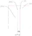
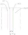
图5为本发明实施例提供的电芯卷绕校准方法中获取的图像的示意图;Fig. 5 is a schematic diagram of images obtained in the cell winding calibration method provided by the embodiment of the present invention;
图6为图3中步骤S20至步骤S30的具体流程示意图;FIG. 6 is a schematic flow chart of steps S20 to S30 in FIG. 3;
图7为本发明另一实施例提供的电芯卷绕校准设备的结构示意图;Fig. 7 is a schematic structural diagram of a cell winding calibration device provided by another embodiment of the present invention;
图8为本发明另一实施例提供的电芯卷绕校准方法中进一步的流程示意图;Fig. 8 is a further schematic flow chart of the cell winding calibration method provided by another embodiment of the present invention;
图9为本发明又一实施例提供的电芯卷绕校准设备的结构示意图;Fig. 9 is a schematic structural diagram of a cell winding calibration device provided by another embodiment of the present invention;
图10为图8中步骤S80和步骤S90的具体流程以及进一步的流程示意图;FIG. 10 is a specific flow diagram of step S80 and step S90 in FIG. 8 and a further schematic flow diagram;
图11为图6中步骤S41和步骤S42的具体流程以及进一步的流程示意图;Fig. 11 is the concrete process of step S41 and step S42 in Fig. 6 and further schematic flow chart;
图12为图10中步骤S101和步骤S102的具体流程以及进一步的流程示意图;FIG. 12 is a specific flow diagram of step S101 and step S102 in FIG. 10 and a further schematic flow diagram;
图13a为本发明实施例提供的电芯卷绕校准方法中第一相机采集到的图像示意图;Fig. 13a is a schematic diagram of images collected by the first camera in the cell winding calibration method provided by the embodiment of the present invention;
图13b为本发明实施例提供的电芯卷绕校准方法中第二相机采集到的图像示意图;Fig. 13b is a schematic diagram of images collected by the second camera in the cell winding calibration method provided by the embodiment of the present invention;
图13c为本发明实施例提供的电芯卷绕校准方法中第三相机采集到的图像示意图;Fig. 13c is a schematic diagram of images collected by the third camera in the cell winding calibration method provided by the embodiment of the present invention;
图13d为本发明实施例提供的电芯卷绕校准方法中第四相机采集到的图像示意图。Fig. 13d is a schematic diagram of images collected by the fourth camera in the cell winding calibration method provided by the embodiment of the present invention.
具体实施方式中的附图标号如下:The reference numerals in the specific embodiment are as follows:
物平面10,成像平面20,透镜光心30,焦点40,隔膜50,摆正位置51;
电芯卷绕校准设备100,卷绕单元110,光束发射单元120,第一基准线121,第二基准线122,第三基准线123,第四基准线124,第一线性光束发射器1201,第二线性光束发射器1202,第三线性光束发射器1203,第四线性光束发射器1204,发射器导轨1205,第一发射器滑块1206,第二发射器导轨1207,图像采集单元130,第一相机131,第二相机132,第三相机133,第四相机134,第一相机导轨135,第二相机导轨136,第一相机滑块1301,第二相机滑块1302,第三相机滑块1303,第四相机滑块1304,控制单元140,校准单元150;Cell winding
卷绕基材200,已卷绕层210,待卷绕层220,第一极片201,第一极片一端边缘2011,第一极片另一端边缘2012,第一隔膜202,第一隔膜一端边缘2021,第一隔膜另一端边缘2022,第二极片203,第二极片一端边缘2031,第二极片另一端边缘2032,第二隔膜204,第二隔膜一端边缘2041,第二隔膜另一端边缘2042。Winding
具体实施方式Detailed ways
下面将结合附图对本发明技术方案的实施例进行详细的描述。以下实施例仅用于更加清楚地说明本发明的技术方案,因此只作为示例,而不能以此来限制本发明的保护范围。Embodiments of the technical solutions of the present invention will be described in detail below in conjunction with the accompanying drawings. The following examples are only used to illustrate the technical solutions of the present invention more clearly, and therefore are only examples, rather than limiting the protection scope of the present invention.
需要注意的是,除非另有说明,本发明实施例使用的技术术语或者科学术语应当为本发明实施例所属领域技术人员所理解的通常意义。It should be noted that, unless otherwise specified, the technical terms or scientific terms used in the embodiments of the present invention shall have common meanings understood by those skilled in the art to which the embodiments of the present invention belong.
在本发明实施例的描述中,技术术语“中心”“纵向”“横向”“长度”“宽度”“厚度”“上”“下”“前”“后”“左”“右”“竖直”“水平”“顶”“底”“内”“外”“顺时针”“逆时针”“轴向”“径向”“周向”等指示的方位或位置关系为基于附图所示的方位或位置关系,仅是为了便于描述本发明实施例和简化描述,而不是指示或暗示所指的装置或元件必须具有特定的方位、以特定的方位构造和操作,因此不能理解为对本发明实施例的限制。In the description of the embodiments of the present invention, the technical terms "center", "longitudinal", "transverse", "length", "width", "thickness", "upper", "lower", "front", "rear", "left", "right", "vertical" "Horizontal", "Top", "Bottom", "Inner", "Outer", "Clockwise", "Counterclockwise", "Axial", "Radial", "Circumferential", etc. indicate the orientation or positional relationship based on the drawings Orientation or positional relationship is only for the convenience of describing the embodiment of the present invention and simplifying the description, and does not indicate or imply that the device or element referred to must have a specific orientation, be constructed and operated in a specific orientation, and therefore cannot be understood as an implementation of the present invention. Example limitations.
此外,技术术语“第一”“第二”等仅用于描述目的,而不能理解为指示或暗示相对重要性或者隐含指明所指示的技术特征的数量。在本发明实施例的描述中,“多个”的含义是两个以上,除非另有明确具体的限定。In addition, technical terms such as "first" and "second" are used for descriptive purposes only, and cannot be interpreted as indicating or implying relative importance or implicitly specifying the quantity of indicated technical features. In the description of the embodiments of the present invention, "plurality" means two or more, unless otherwise specifically defined.
在本发明实施例的描述中,除非另有明确的规定和限定,技术术语“安装”“相连”“连接”“固定”等术语应做广义理解,例如,可以是固定连接,也可以是可拆卸连接,或成一体;也可以是机械连接,也可以是电连接;可以是直接相连,也可以通过中间媒介间接相连,可以是两个元件内部的连通或两个元件的相互作用关系。对于本领域的普通技术人员而言,可以根据具体情况理解上述术语在本发明实施例中的具体含义。In the description of the embodiments of the present invention, unless otherwise clearly stipulated and limited, terms such as "installation", "connection", "connection" and "fixation" should be understood in a broad sense, for example, it can be a fixed connection or a fixed connection. Disassembled connection, or integration; it can also be a mechanical connection, or an electrical connection; it can be a direct connection, or an indirect connection through an intermediary, and it can be the internal communication of two components or the interaction relationship between two components. Those of ordinary skill in the art can understand the specific meanings of the above terms in the embodiments of the present invention according to specific situations.
在本发明实施例的描述中,除非另有明确的规定和限定,第一特征在第二特征“上”或“下”可以是第一和第二特征直接接触,或第一和第二特征通过中间媒介间接接触。而且,第一特征在第二特征“之上”“上方”和“上面”可是第一特征在第二特征正上方或斜上方,或仅仅表示第一特征水平高度高于第二特征。第一特征在第二特征“之下”“下方”和“下面”可以是第一特征在第二特征正下方或斜下方,或仅仅表示第一特征水平高度小于第二特征。In the description of the embodiments of the present invention, unless otherwise specified and limited, the first feature may be in direct contact with the first feature or the second feature "on" or "under" the second feature. Indirect contact through intermediaries. Moreover, "above" and "above" and "above" the first feature on the second feature may mean that the first feature is directly above or obliquely above the second feature, or simply means that the first feature is higher in level than the second feature. "Below" and "beneath" the first feature may mean that the first feature is directly below or obliquely below the second feature, or simply mean that the first feature is less horizontally than the second feature.
现有电芯在卷绕过程中,首先设定好图像采集装置的焦距,图像采集装置例如可以是相机、图像传感器等,获得物平面与像平面的之间的比例关系,通过该比例关系实现对卷绕电芯中极片与隔膜边缘之间的距离的测量。During the winding process of the existing battery core, the focal length of the image acquisition device is first set. The image acquisition device can be a camera, an image sensor, etc., to obtain the proportional relationship between the object plane and the image plane, and realize the The measurement of the distance between the pole piece and the edge of the separator in a wound cell.
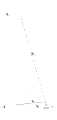
具体地,请参阅图1,图中为图像采集装置成像测距的原理示意图。如图中所示,物平面10上A点与B点之间的距离为d1,d1为需要通过计算求得的未知量;Specifically, please refer to FIG. 1 , which is a schematic diagram of the principles of imaging and ranging by an image acquisition device. As shown in the figure, the distance between point A and point B on the
物平面10上A点与B点在成像平面20上分别为A’点和B’点,在成像平面20中A’点与B’点之间的距离为d2,根据成像图片中A’点与B’点之间所包含的像素数和成像图片的分辨率,通过像素、分辨率、图像尺寸的换算公式:Point A and point B on the

即
u为物距,即被采集的物平面10至图像采集装置的透镜光心30的距离,u在设置被采集物和图像采集装置的位置时可以测量得出;u is the object distance, that is, the distance from the collected
f为焦距,即焦点40至透镜光心30的距离,f为在图像采集装置进行采集前标定的已知量;f is the focal length, that is, the distance from the
v为像距,即透镜光心30至成像平面20之间的距离,通过成像公式:v is the image distance, that is, the distance between the lens

可以得出v的值;The value of v can be obtained;
至此,已知d2、物距u及像距v,根据成像比例关系:So far, given d2 , object distance u and image distance v, according to the relationship of imaging ratio:

得出
对于上述测距方式,电芯随着卷绕次数增加,其厚度相应增加,即物距u减小,而由于焦距固定,若电芯的厚度增加量较大,会造成图像虚化,从而由于隔膜和极片边缘距离较小,并且成像不清晰,影响到测量的准确性。For the distance measuring method above, as the number of windings increases, the thickness of the battery core increases accordingly, that is, the object distance u decreases, and because the focal length is fixed, if the thickness of the battery core increases a lot, the image will be blurred, thus due to The distance between the diaphragm and the edge of the pole piece is small, and the imaging is not clear, which affects the accuracy of the measurement.
当采集图像时卷绕电芯的隔膜或极片存在倾斜时,会造成测距出错的情况。具体请参阅图2,图中为当隔膜50存在倾斜时图像采集装置的测距原理图,图中物平面10处的实线部分表示存在倾斜的隔膜50,物平面10处的虚线部分表示隔膜50贴合物平面10后所处的摆正位置51。When the diaphragm or pole piece of the winding cell is tilted when the image is collected, it will cause errors in distance measurement. Please refer to FIG. 2 for details. The figure is a schematic diagram of the ranging principle of the image acquisition device when the
如图中所示,对隔膜50边缘正确的图像采集点本来应当是物平面10上的C点,但是由于隔膜50存在倾斜,因此实际的图像采集点变成了物平面10上的D点,从而造成隔膜50边缘采集错误,使后续对隔膜50与极片间的距离测量出错,若极片不存在倾斜,则测距误差为C点与D点之间的距离d0。As shown in the figure, the correct image acquisition point for the edge of the
当隔膜或极片存在倾斜时,测距出错容易将合格的电芯视为不合格品而淘汰,将不合格的电芯视为合格品,存在过杀和漏杀风险。When the diaphragm or pole piece is tilted, it is easy to make a mistake in distance measurement, and it is easy to regard qualified cells as unqualified products and eliminate them, and unqualified cells as qualified products, there is a risk of over killing and missing killing.
基于上述问题,本申请发明人在研究中发现,在电芯的卷绕基材上形成两条相互平行的第一基准线和第二基准线,保证第一基准线和第二基准线之间的第一基准距离不变,通过获取第一基准线距离所包含的像素数,确定单个像素所对应的实际距离,进而可以准确有效地确定卷绕基材边缘的实时位置信息,并根据实时位置信息进行校准。Based on the above problems, the inventors of the present application found in the research that two first reference lines and second reference lines parallel to each other are formed on the winding base material of the battery core to ensure that the distance between the first reference line and the second reference line is The first reference distance remains unchanged. By obtaining the number of pixels contained in the first reference line distance, the actual distance corresponding to a single pixel can be determined, and then the real-time position information of the edge of the winding substrate can be accurately and effectively determined, and according to the real-time position information to calibrate.
即使随着卷绕次数增加,卷绕基材的厚度相应增加,图像出现虚化,但是由于第一基准线和第二基准线为在卷绕基材上形成的标识线,因此第一基准线和第二基准线在成像中更易识别,且卷绕基材的边缘至第一基准线或第二基准线的距离更大,在成像中更加容易进行像素读取和识别,由于第一基准距离固定不变,因此可以有效保证侧得的单个像素所对应的实际距离准确无误,进而准确地确定卷绕基材边缘的实时位置信息,并进行校准。Even if the thickness of the winding base material increases with the number of winding times, the image appears blurred, but since the first reference line and the second reference line are marking lines formed on the winding base material, the first reference line and the second reference line are easier to identify in imaging, and the distance from the edge of the winding substrate to the first reference line or the second reference line is larger, and it is easier to read and identify pixels in imaging, because the first reference distance Therefore, it can effectively ensure that the actual distance corresponding to the obtained single pixel is accurate, and then accurately determine the real-time position information of the edge of the winding substrate and perform calibration.
当卷绕基材存在倾斜时,第一基准线和第二基准线由于在卷绕基材表面形成,因此也会随之倾斜,进而可以通过测量卷绕基材边缘与第一基准线或第二基准线之间距离所包含的像素数,准确地确定卷绕基材边缘的实时位置信息,并进行校准。When the winding substrate is inclined, the first reference line and the second reference line are formed on the surface of the winding substrate, so they will also be inclined accordingly, and then the edge of the winding substrate and the first reference line or the second reference line can be measured The number of pixels contained in the distance between the two reference lines can accurately determine the real-time position information of the edge of the winding substrate, and perform calibration.
请参阅图3,图中示出了本申请一实施例提供的电芯卷绕校准方法的流程。电芯卷绕校准方法包括:Please refer to FIG. 3 , which shows the flow of a battery winding calibration method provided by an embodiment of the present application. Cell winding calibration methods include:
S10:获取第一基准线与第二基准线之间的第一基准距离;S10: Obtain a first reference distance between the first reference line and the second reference line;
其中,第一基准线和第二基准线为在卷绕基材上形成的相互平行的标识线,第一基准距离在电芯卷绕过程中保持不变;Wherein, the first reference line and the second reference line are marking lines parallel to each other formed on the winding base material, and the first reference distance remains unchanged during the winding process of the cell;
具体地,例如可以通过将光束发射单元对准卷绕基材设置,从而在卷绕基材表面形成两条相互平行的标识线;Specifically, for example, by aligning the beam emitting unit with the winding substrate, two marking lines parallel to each other are formed on the surface of the winding substrate;
S20:获取第一基准距离所包含的基准像素数;S20: Obtain the number of reference pixels included in the first reference distance;
具体地,可以通过图像采集单元,例如普通相机、线阵相机等,对卷绕基材表面进行图像采集,并通过控制单元获取采集的图像中第一基准距离所包含的基准像素数,即第一基准线与第二基准线之间的距离在采集的图像中所包含的像素块的数量;Specifically, an image acquisition unit, such as an ordinary camera, a line scan camera, etc., can be used to collect images on the surface of the winding substrate, and the control unit can obtain the number of reference pixels contained in the first reference distance in the collected image, that is, the first reference pixel number. The distance between the first reference line and the second reference line includes the number of pixel blocks in the collected image;
S30:根据第一基准距离和第一基准距离所包含的基准像素数,确定单个像素所对应的实际距离;S30: Determine the actual distance corresponding to a single pixel according to the first reference distance and the number of reference pixels included in the first reference distance;
具体为:第一基准距离/第一基准距离所包含的基准像素数=单个像素所对应的实际距离;Specifically: the first reference distance/the number of reference pixels included in the first reference distance=the actual distance corresponding to a single pixel;
S40:获取卷绕基材边缘与第一基准线或第二基准线之间距离所包含的实际像素数;S40: Obtain the actual number of pixels contained in the distance between the edge of the winding substrate and the first reference line or the second reference line;
同理,通过图像采集单元对卷绕基材进行图像采集后,通过控制单元获取采集到的图像中卷绕基材边缘与第一基准线或第二基准线之间的距离所包含的像素块的数量,具体可以是隔膜边缘与第一基准线或第二基准线之间的距离所包含的像素块的数量,也可以是极片边缘与第一基准线或第二基准线之间的距离所包含的像素块的数量;Similarly, after the image acquisition unit is used to collect the image of the winding substrate, the control unit is used to obtain the pixel blocks contained in the distance between the edge of the winding substrate and the first reference line or the second reference line in the collected image. Specifically, it can be the number of pixel blocks included in the distance between the edge of the diaphragm and the first reference line or the second reference line, or the distance between the edge of the pole piece and the first reference line or the second reference line the number of contained pixel blocks;
S50:根据卷绕基材边缘与第一基准线或第二基准线之间距离所包含的实际像素数和单个像素所对应的实际距离,确定卷绕基材边缘的实时位置信息;S50: Determine the real-time position information of the edge of the winding substrate according to the actual number of pixels contained in the distance between the edge of the winding substrate and the first reference line or the second reference line and the actual distance corresponding to a single pixel;
控制单元通过获取的实际像素数和单个像素所对应的实际距离,确定卷绕基材边缘与第一基准线或第二基准线之间的实际距离,从而确定卷绕基材边缘的实时位置信息,具体为:The control unit determines the actual distance between the edge of the winding substrate and the first reference line or the second reference line by obtaining the actual number of pixels and the actual distance corresponding to a single pixel, so as to determine the real-time position information of the edge of the winding substrate ,Specifically:
实际像素数×单个像素所对应的实际距离=卷绕基材边缘与第一基准线或第二基准线之间的实际距离;The actual number of pixels × the actual distance corresponding to a single pixel = the actual distance between the edge of the winding substrate and the first reference line or the second reference line;
S60:根据卷绕基材边缘的实时位置信息对卷绕基材进行校准;S60: Calibrate the winding substrate according to the real-time position information of the edge of the winding substrate;
具体可以为控制单元通过将卷绕基材边缘与第一基准线或第二基准线之间的实际距离与理论距离进行比较后,控制校准单元,例如机械手等,对卷绕基材边缘的位置进行调整校准。Specifically, after the control unit compares the actual distance between the edge of the winding substrate and the first reference line or the second reference line with the theoretical distance, it controls the calibration unit, such as a manipulator, to adjust the position of the edge of the winding substrate. Make adjustments and calibrations.
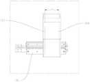
请参阅图4,图中示出了本申请一实施例提供的采用电芯卷绕校准方法的电芯卷绕校准设备100的结构。电芯卷绕校准设备100包括:卷绕单元110、光束发射单元120、图像采集单元130、控制单元140和校准单元150。卷绕单元110用于绕设卷绕基材200,光束发射单元120用于在卷绕基材200上形成第一基准线121和第二基准线122,图像采集单元130用于对卷绕基材200进行图像采集,控制单元140用于获取图像数据进行分析检测,以确定卷绕基材200边缘的实时位置信息,并根据实时位置信息控制校准单元150对卷绕基材200的进行校准或控制卷绕单元110对卷绕基材200进行卷绕。Please refer to FIG. 4 , which shows the structure of a cell winding
需要说明的是,在卷绕基材200的卷绕过程中,可以分别对每层进行如上步骤,当卷绕基材200边缘的实时位置信息正确时,控制单元140控制卷绕单元110对下一层卷绕基材200进行卷绕,并重复进行如上步骤,当卷绕基材200边缘的实时位置信息不正确时,控制单元140控制校准单元150对卷绕基材200进行校准后,对卷绕基材200再进行一次如上步骤,直至校准正确后,再进行下一层的卷绕。It should be noted that, during the winding process of the winding
本申请根据获取的第一基准线与第二基准线之间的第一基准距离以及第一基准距离所包含的基准像素数,确定单个像素所对应的实际距离,由于第一基准线和第二基准线为在卷绕基材上形成的相互平行的标识线,并且第一基准距离在电芯卷绕过程中保持不变,因此即使卷绕基材随着卷绕过程厚度增加,物距发生变化,采集的图像分辨率随之改变,依然可以准确无误地确定单个像素所对应的实际距离。由于第一基准线和第二基准线为在卷绕基材上形成的相互平行的标识线,因此第一基准线和第二基准线在成像中更加容易识别,并且为了避免由于图像虚化以及隔膜与极片边缘之间距离过小而造成隔膜与极片边缘之间距离较难识别清楚,通过读取卷绕基材中隔膜及极片边缘至第一基准线或第二基准线之间距离所包含的像素数,并结合单个像素所对应的实际距离,以准确无误地确定卷绕基材边缘的实时位置信息,进而对卷绕基材的边缘准确有效地进行校准,保证卷绕基材卷绕的合格率。The present application determines the actual distance corresponding to a single pixel based on the obtained first reference distance between the first reference line and the second reference line and the number of reference pixels included in the first reference distance. Since the first reference line and the second reference line The reference line is the marking line parallel to each other formed on the winding substrate, and the first reference distance remains unchanged during the winding process of the battery core, so even if the thickness of the winding substrate increases with the winding process, the object distance will The resolution of the collected image changes accordingly, and the actual distance corresponding to a single pixel can still be accurately determined. Since the first reference line and the second reference line are marking lines parallel to each other formed on the winding substrate, the first reference line and the second reference line are easier to identify in imaging, and in order to avoid image blurring and The distance between the diaphragm and the edge of the pole piece is too small, which makes it difficult to identify the distance between the diaphragm and the edge of the pole piece. By reading the distance between the diaphragm and the edge of the pole piece in the winding substrate and the first reference line or the second reference line The number of pixels included in the distance, combined with the actual distance corresponding to a single pixel, can accurately determine the real-time position information of the edge of the winding substrate, and then accurately and effectively calibrate the edge of the winding substrate to ensure that the winding substrate The qualified rate of material winding.
请参阅图5,图中示出了本申请一实施例提供的电芯卷绕校准方法中获取的图像。根据本申请的一些实施例,第一基准距离所包含的基准像素数至少为一个。Please refer to FIG. 5 , which shows the images obtained in the cell winding calibration method provided by an embodiment of the present application. According to some embodiments of the present application, the number of reference pixels included in the first reference distance is at least one.
第一基准距离l1所包含的基准像素数至少为一个是指在图像采集单元对卷绕基材进行采集的图像中,第一基准线和第二基准线之间的距离l1至少为一个像素块,目的是保证可以准确地得出单个像素所对应的实际距离,避免由于图像中第一基准距离过小造成第一基准距离所包含的基准像素数获取失败或出错。The number of reference pixels contained in the first reference distancel1 is at least one means that in the image captured by the image acquisition unit on the winding substrate, the distancel1 between the first reference line and the second reference line is at least one The purpose of the pixel block is to ensure that the actual distance corresponding to a single pixel can be accurately obtained, and to avoid failure or error in obtaining the number of reference pixels included in the first reference distance because the first reference distance in the image is too small.
请再次参阅图4,根据本申请的一些实施例,卷绕基材200包括已经完成卷绕操作的已卷绕层210和即将进行卷绕操作的待卷绕层220。第一基准线121和第二基准线122为在已卷绕层210外侧面和待卷绕层220内侧面形成的相互平行的标识线。Please refer to FIG. 4 again, according to some embodiments of the present application, the
卷绕基材200一般依次分为正极极片、第一隔膜、负极极片和第二隔膜,隔膜的表面积要比正积极片和负极极片的表面积大,以保证隔膜将正积极片和负极极片完全隔离,避免极片间发生接触造成短路风险。隔膜一般具有一定的透明性,而极片不具有透明性,因此,考虑到从卷绕基材200的一面采集图像时,仅能看到一个极片和一个隔膜的边缘,远离图像采集单元130的极片和隔膜无法采集到其边缘,本申请通过在已卷绕层210外侧面和待卷绕层220内侧面均形成第一基准线121和第二基准线122,并一次同时对已卷绕层210外侧面和待卷绕层220内侧面进行图像采集,分别实现对两个极片和两个隔膜边缘的图像采集和识别。The winding
需要说明的是,由于卷绕基材200为圆弧表面,因此其不同表面处的第一基准线121和第二基准线122至图像采集单元130的距离是不相等的,对于次,需要保证第一基准线121和第二基准线122到图像采集单元130的最远处与最近处之间的距离小于图像采集单元130的景深,从而保证图像采集单元130采集到的图像中卷绕基材200的全部表面清晰。景深是指在摄影机镜头或其他成像器前沿能够取得清晰图像的成像所测定的被摄物体前后距离范围。光圈、镜头、及焦平面到拍摄物的距离是影响景深的重要因素。It should be noted that since the winding
进一步地,为了提高测距的精确度,图像采集单元130可以采用线阵相机。线阵相机,是采用线阵图像传感器的相机,线阵图像传感器以CCD为主。CCD是电荷耦合器件(charge coupled device)的简称,它能够将光线变为电荷并将电荷存储及转移,也可将存储之电荷取出使电压发生变化,因此是理想的CCD相机元件,以其构成的CCD相机具有体积小、重量轻、不受磁场影响、具有抗震动和撞击之特性而被广泛应用。Further, in order to improve the accuracy of distance measurement, the
线阵相机的典型应用领域是检测连续的材料,例如金属、塑料、纸和纤维等。被检测的物体通常匀速运动,利用一台或多台相机对其逐行连续扫描,以达到对其整个表面均匀检测。可以对其图象一行一行进行处理,或者对由多行组成的面阵图象进行处理。另外线阵相机非常适合测量场合,这要归功于传感器的高分辨率,它可以准确测量到微米。线阵相机顾名思义是呈“线”状的。虽然也是二维图像,但极长,几K的长度,而宽度却只有几个象素的而已。一般上只在两种情况下使用这种相机:一、被测视野为细长的带状,多用于滚筒上检测的问题。二、需要极大的视野或极高的精度。A typical field of application for line scan cameras is the detection of continuous materials such as metals, plastics, paper and fibers. The detected object usually moves at a constant speed, and one or more cameras are used to continuously scan it line by line to achieve uniform detection of its entire surface. It can process the image line by line, or process the area array image composed of multiple lines. In addition, line scan cameras are very suitable for measurement applications, thanks to the high resolution of the sensor, it can measure accurately down to the micron. As the name suggests, a line scan camera is in the shape of a "line". Although it is also a two-dimensional image, it is extremely long, with a length of several K, but a width of only a few pixels. Generally, this kind of camera is only used in two situations: 1. The field of view to be measured is a slender strip, which is mostly used for detection on the roller. Second, a large field of view or high precision is required.
请参阅图6,图中示出了本申请一实施例提供的电芯卷绕校准方法中步骤S20至步骤S30的具体流程。根据本申请的一些实施例,步骤S20至步骤S30包括:Please refer to FIG. 6 , which shows the specific flow from step S20 to step S30 in the cell winding calibration method provided by an embodiment of the present application. According to some embodiments of the present application, steps S20 to S30 include:
S21:在待卷绕层内侧面获取第一基准距离所包含的第一基准像素数;S21: Obtain the first reference pixel number included in the first reference distance on the inner side of the layer to be wound;
S31:根据第一基准距离和第一基准像素数,确定单个像素所对应的第一实际距离;S31: Determine a first actual distance corresponding to a single pixel according to the first reference distance and the first reference pixel number;
S22:在已卷绕层外侧面获取第一基准距离所包含的第二基准像素数;S22: Obtain the second reference pixel number included in the first reference distance on the outer surface of the wound layer;
S32:根据第一基准距离和第二基准像素数,确定单个像素所对应的第二实际距离。S32: Determine a second actual distance corresponding to a single pixel according to the first reference distance and the second reference pixel number.
具体地,请参阅图7,图中示出了本申请一实施例提供的采用上述电芯卷绕校准方法的电芯卷绕校准设备100的结构。其中图像采集单元130包括上下设置的两个相机,其中一个用于对待卷绕层220内侧面进行图像采集,另一个用于对已卷绕层210外侧面进行图像采集。Specifically, please refer to FIG. 7 , which shows the structure of a cell winding
通过分别对待卷绕层内侧面和已卷绕层外侧面进行图像采集获得待卷绕层内侧面的图像和已卷绕层外侧面的图像,在待卷绕层内侧面图像和已卷绕层外侧面图像中获取第一基准距离所包含的第一基准像素数和第二基准像素数,根据第一基准距离和第一基准像素数、第二基准像素数,确定两个图像中单个像素所对应的第一实际距离和第二实际距离,可以有效避免由于图像采集单元景深较小而造成卷绕基材的成像中部分表面模糊,对待卷绕层内侧面和已卷绕层外侧面分开进行图像采集,保证待卷绕层内侧面和已卷绕层外侧面的成像均具有良好的分辨率,图像清晰,有利于提升对卷绕基材边缘位置检测的精准度。The image of the inner side of the layer to be wound and the image of the outer side of the wound layer are obtained by image acquisition respectively on the inner side of the layer to be wound and the outer side of the wound layer. Obtain the first reference pixel number and the second reference pixel number contained in the first reference distance in the outer side image, and determine the number of single pixels in the two images according to the first reference distance, the first reference pixel number, and the second reference pixel number. The corresponding first actual distance and second actual distance can effectively avoid part of the surface blurring in the imaging of the winding substrate due to the small depth of field of the image acquisition unit, and separate the inner side of the to-be-wound layer from the outer side of the wound layer. Image acquisition ensures that the imaging of the inner side of the layer to be wound and the outer side of the wound layer has good resolution and clear images, which is conducive to improving the accuracy of edge position detection of the wound substrate.
请再次参阅图6,图中还示出了本申请一实施例提供的电芯卷绕校准方法中步骤S40的具体流程。根据本申请的一些实施例,步骤S40包括:Please refer to FIG. 6 again, which also shows the specific flow of step S40 in the cell winding calibration method provided by an embodiment of the present application. According to some embodiments of the present application, step S40 includes:
S41:获取已卷绕层外侧面的边缘与第一基准线或第二基准线之间距离所包含的实际像素数;S41: Obtain the actual number of pixels contained in the distance between the edge of the outer surface of the wound layer and the first reference line or the second reference line;
S42:获取待卷绕层内侧面的边缘与第一基准线或第二基准线之间距离所包含的实际像素数。S42: Obtain the actual number of pixels contained in the distance between the edge of the inner surface of the layer to be wound and the first reference line or the second reference line.
同样地,上下两个相机分别对已卷绕层外侧面和待卷绕层内侧面进行图像采集后,通过控制单元先获取其中一张采集到的图像中待卷绕层内侧面边缘与第一基准线或第二基准线之间距离所包含的实际像素数,从而获得卷绕基材中一个极片和一个隔膜到第一基准线或第二基准线之间距离所包含的实际像素数,进而通过该图像中单个像素所对应的第一实际距离确定极片和隔膜边缘的位置信息;然后控制单元再获取另外一张采集到的图像中已卷绕层外侧面边缘与第一基准线或第二基准线之间距离所包含的实际像素数,从而获得卷绕基材中另一极片和另一隔膜到第一基准线或第二基准线之间距离所包含的实际像素数,进而通过该图像中单个像素所对应的第二实际距离确定另一极片和隔膜的位置信息。Similarly, after the upper and lower cameras respectively collect images of the outer side of the wound layer and the inner side of the layer to be wound, the control unit first obtains the edge of the inner side of the layer to be wound in one of the collected images and the first The actual number of pixels included in the distance between the reference line or the second reference line, so as to obtain the actual number of pixels included in the distance between a pole piece and a diaphragm in the winding substrate and the first reference line or the second reference line, Then, the position information of the pole piece and the edge of the diaphragm is determined by the first actual distance corresponding to a single pixel in the image; then the control unit obtains the distance between the outer edge of the wound layer and the first reference line or the first reference line in another collected image. The actual number of pixels included in the distance between the second reference lines, thereby obtaining the actual number of pixels included in the distance between another pole piece and another diaphragm in the winding substrate to the first reference line or the second reference line, and then The position information of the other pole piece and the diaphragm is determined through the second actual distance corresponding to a single pixel in the image.
分别获取已卷绕层外侧面的边缘和待卷绕层内侧面的边缘与第一基准线或第二基准线之间距离所包含的实际像素数,进而实现对卷绕基材中两个极片和两个隔膜边缘的位置信息的精确检测。The actual number of pixels included in the distance between the edge of the outer side of the wound layer and the inner side of the layer to be wound and the first reference line or the second reference line is obtained respectively, and then the two poles in the wound substrate are realized. Precise detection of positional information of the sheet and the two diaphragm edges.
请参阅图8,图中示出了本申请一实施例提供的电芯卷绕校准方法的进一步流程。根据本申请的一些实施例,电芯卷绕方法还包括:Please refer to FIG. 8 , which shows a further flow of the cell winding calibration method provided by an embodiment of the present application. According to some embodiments of the present application, the cell winding method further includes:
S70:获取第三基准线与第四基准线之间的第二基准距离。S70: Acquire a second reference distance between the third reference line and the fourth reference line.
其中第三基准线和第四基准线位于卷绕基材上与第一基准线和第二基准线相对的一端,为相互平行的标识线,第二基准距离在电芯卷绕过程中保持不变。Wherein the third reference line and the fourth reference line are located at the opposite end of the winding base material to the first reference line and the second reference line, which are marking lines parallel to each other, and the second reference distance is kept constant during the winding process of the battery core. Change.
值得注意的是,图像采集单元为了保证图像采集和检测的精度,一般视场范围较小,即取景成像的面积较小,而对于一些较大的卷绕基材,当图像采集单元取景成像的宽度小于卷绕基材的宽度时,一张图像就无法同时采集到卷绕基材两端的边缘。It is worth noting that, in order to ensure the accuracy of image acquisition and detection, the image acquisition unit generally has a small field of view, that is, the area for viewing and imaging is small. When the width is smaller than the width of the rolled substrate, one image cannot capture both edges of the rolled substrate at the same time.
请参阅图9,图中示出了本申请一实施例提供的采用电芯卷绕校准方法的另一种电芯卷绕校准设备。基于上述问题,本申请通过在卷绕基材200一端的表面形成第一基准线121和第二基准线122,另一端形成第三基准线123和第四基准线124,从而保证当需要对卷绕基材200两端的边缘分别成像时,每个图像中均具有双基准线,进而保证检测的准确性,并且可以减小图像采集单元的取景成像的面积,优化采集的图像,提高检测的精度。Please refer to FIG. 9 , which shows another battery winding calibration device using a battery winding calibration method provided by an embodiment of the present application. Based on the above problems, the present application forms the
请再次参阅图8,根据本申请的一些实施例,电芯卷绕校准方法进一步包括:Please refer to FIG. 8 again. According to some embodiments of the present application, the cell winding calibration method further includes:
S80:获取第二基准距离所包含的基准像素数;S80: Obtain the number of reference pixels included in the second reference distance;
S90:根据第二基准距离和第二基准距离所包含的基准像素数,确定单个像素所对应的实际距离。S90: Determine an actual distance corresponding to a single pixel according to the second reference distance and the number of reference pixels included in the second reference distance.
通过获取图像中第二基准距离所包含的基准像素数,根据第二基准距离和第二基准距离所包含的基准像素数,确定该图像中单个像素所对应的实际距离,进而在该图像中实现对卷绕基材另一端边缘的位置检测。By obtaining the number of reference pixels included in the second reference distance in the image, according to the second reference distance and the number of reference pixels included in the second reference distance, the actual distance corresponding to a single pixel in the image is determined, and then implemented in the image The position detection of the other end edge of the rolled substrate.
请继续参阅图8,根据本申请的一些实施例,电芯卷绕校准方法进一步包括:Please continue to refer to FIG. 8, according to some embodiments of the present application, the cell winding calibration method further includes:
S100:获取卷绕基材边缘与第三基准线或第四基准线之间距离所包含的实际像素数。S100: Acquire the actual number of pixels included in the distance between the edge of the wrapping substrate and the third reference line or the fourth reference line.
通过获取卷绕基材边缘与第三基准线或第四基准线之间距离所包含的实际像素数,结合步骤S90中确定的单个像素所对应的实际距离,确定卷绕基材另一端的边缘与第三基准线或第四基准线之间的实际距离,得到卷绕基材另一端边缘的实时位置信息,进而判断卷绕基材另一端边缘的位置是否需要校准。Determine the edge of the other end of the winding substrate by obtaining the actual number of pixels contained in the distance between the edge of the winding substrate and the third reference line or the fourth reference line, combined with the actual distance corresponding to the single pixel determined in step S90 The real-time position information of the edge of the other end of the rolled substrate is obtained from the actual distance from the third reference line or the fourth reference line, and then it is judged whether the position of the edge of the other end of the rolled substrate needs to be calibrated.
请参阅图10,图中示出了本申请一实施例提供的电芯卷绕校准方法中步骤S80和步骤S90的具体流程。根据本申请的一些实施例,步骤S80和步骤S90包括:Please refer to FIG. 10 , which shows the specific flow of steps S80 and S90 in the cell winding calibration method provided by an embodiment of the present application. According to some embodiments of the present application, step S80 and step S90 include:
S81:在待卷绕层内侧面获取第二基准距离所包含的第三基准像素数;S81: Obtain a third reference pixel number included in the second reference distance on the inner side of the layer to be wound;
S91:根据第二基准距离和第三基准像素数,确定单个像素所对应的第三实际距离;S91: Determine a third actual distance corresponding to a single pixel according to the second reference distance and the third reference pixel number;
S82:在已卷绕层外侧面获取第二基准距离所包含的第四基准像素数;S82: Obtain the fourth reference pixel number contained in the second reference distance on the outer surface of the wound layer;
S92:根据第二基准距离和第四基准像素数,确定单个像素所对应的第四实际距离。S92: Determine a fourth actual distance corresponding to a single pixel according to the second reference distance and the fourth reference pixel number.
具体地,请再次参阅图9,图像采集单元130可以包括上下左右设置的四个相机,其中一侧的上下两个相机分别用于对已卷绕层210和待卷绕层220一端的边缘进行图像采集,另一侧的上下两个相机分别用于对已卷绕层210和待卷绕层220另一端的边缘进行图像采集。Specifically, referring to FIG. 9 again, the
通过在待卷绕层内侧面获取第二基准距离所包含的第三基准像素数,根据第二基准距离和第三基准像素数,确定单个像素所对应的第三实际距离;在已卷绕层外侧面获取第二基准距离所包含的第四基准像素数,根据第二基准距离和第四基准像素数,确定单个像素所对应的第四实际距离,解决了由于图像采集范围有限而造成卷绕基材两侧无法同时采集到一张图像上的问题,并且可以有效避免由于图像采集单元景深较小而造成卷绕基材的成像中部分表面模糊,对待卷绕层内侧面和已卷绕层外侧面以及每一端均分开进行图像采集,保证待卷绕层内侧面和已卷绕层外侧面的两端边缘成像均具有良好的分辨率,图像清晰,有利于进一步提升对卷绕基材两端边缘位置检测的精准度。Obtain the third reference pixel number contained in the second reference distance on the inner side of the layer to be wound, and determine the third actual distance corresponding to a single pixel according to the second reference distance and the third reference pixel number; The outer side obtains the fourth reference pixel number included in the second reference distance, and determines the fourth actual distance corresponding to a single pixel according to the second reference distance and the fourth reference pixel number, which solves the problem of winding due to the limited image acquisition range The problem that one image cannot be collected on both sides of the substrate at the same time, and it can effectively avoid partial surface blurring in the imaging of the wound substrate due to the small depth of field of the image acquisition unit. The inner side of the wound layer and the wound layer Image acquisition is performed separately on the outer side and each end to ensure that the imaging of the inner side of the layer to be wound and the outer side of the outer side of the wound layer has good resolution and clear images, which is conducive to further improving the accuracy of the two sides of the wound substrate. The accuracy of edge position detection.
请再次参阅图10,根据本申请的一些实施例,电芯卷绕校准方法进一步包括:Please refer to FIG. 10 again. According to some embodiments of the present application, the cell winding calibration method further includes:
S101:获取已卷绕层外侧面的边缘与第三基准线或第四基准线之间距离所包含的实际像素数;S101: Obtain the actual number of pixels included in the distance between the edge of the outer surface of the wound layer and the third reference line or the fourth reference line;
S102:获取待卷绕层内侧面的边缘与第三基准线或第四基准线之间距离所包含的实际像素数。S102: Obtain the actual number of pixels contained in the distance between the edge of the inner surface of the layer to be wound and the third reference line or the fourth reference line.
分别获取已卷绕层外侧面的边缘和待卷绕层内侧面的边缘与第三基准线或第四基准线之间距离所包含的实际像素数,进而实现对卷绕基材中两个极片和两个隔膜其中一端边缘的位置信息更进一步的精确检测。Obtain the actual number of pixels included in the distance between the edge of the outer side of the wound layer and the inner side of the layer to be wound and the third reference line or the fourth reference line, and then realize the two poles in the winding substrate Further accurate detection of the position information of one end edge of the sheet and the two diaphragms.
请再次参阅图10,根据本申请的一些实施例,电芯卷绕校准方法进一步包括:Please refer to FIG. 10 again. According to some embodiments of the present application, the cell winding calibration method further includes:
S110:根据待卷绕层内侧面的边缘与第三基准线或第四基准线之间距离所包含的实际像素数和第三实际距离,确定待卷绕层内侧面的边缘的实时位置信息;S110: Determine the real-time position information of the edge of the inner side of the layer to be wound according to the actual number of pixels contained in the distance between the inner side edge of the layer to be wound and the third reference line or the fourth reference line and the third actual distance;
具体为:Specifically:
待卷绕层内侧面的边缘与第三基准线或第四基准线之间距离所包含的实际像素数×第三实际距离=待卷绕层内侧面的边缘与第三基准线或第四基准线之间的实际距离;The actual number of pixels included in the distance between the edge of the inner side of the layer to be wound and the third reference line or the fourth reference line × the third actual distance = the edge of the inner side of the layer to be wound and the third reference line or the fourth reference the actual distance between the lines;
S120:根据已卷绕层外侧面的边缘与第三基准线或第四基准线之间距离所包含的实际像素数和第四实际距离,确定已卷绕层外侧面的边缘的实时位置信息;S120: Determine the real-time position information of the edge of the outer surface of the wound layer according to the actual number of pixels contained in the distance between the edge of the outer surface of the wound layer and the third reference line or the fourth reference line and the fourth actual distance;
具体为:Specifically:
已卷绕层外侧面的边缘与第三基准线或第四基准线之间距离所包含的实际像素数×第四实际距离=已卷绕层外侧面的边缘与第三基准线或第四基准线之间的实际距离。The actual number of pixels included in the distance between the edge of the outer surface of the wound layer and the third reference line or the fourth reference line × the fourth actual distance = the edge of the outer surface of the wound layer and the third reference line or the fourth reference line The actual distance between the lines.
通过根据待卷绕层内侧面的边缘与第三基准线或第四基准线之间距离所包含的实际像素数和第三实际距离,确定待卷绕层内侧面的边缘的实时位置信息;根据已卷绕层外侧面的边缘与第三基准线或第四基准线之间距离所包含的实际像素数和第四实际距离,确定已卷绕层外侧面的边缘的实时位置信息,实现对待卷绕层内侧面边缘和已卷绕层外侧面边缘的位置准确检测,为后续对卷绕基材的校准提供有效数据支持,便于一次校准到位,提高卷绕基材卷绕成功率。Determine the real-time position information of the edge of the inner side of the layer to be wound according to the actual number of pixels and the third actual distance contained in the distance between the edge of the inner side of the layer to be wound and the third reference line or the fourth reference line; according to The actual number of pixels and the fourth actual distance contained in the distance between the edge of the outer surface of the wound layer and the third reference line or the fourth reference line determine the real-time position information of the edge of the outer surface of the wound layer, and realize the real-time position information of the outer surface of the wound layer. The position of the inner side edge of the winding layer and the outer side edge of the wound layer is accurately detected to provide effective data support for the subsequent calibration of the winding substrate, which is convenient for one-time calibration and improves the success rate of winding the winding substrate.
首先请参阅图9,根据本申请的一些实施例,卷绕基材200由内侧面至外侧面依次为第一极片201、第一隔膜202、第二极片203、第二隔膜204。其次请参阅图11及图12,图11中示出了本申请一实施例提供的电芯卷绕校准方法中步骤S41和S42的具体流程,图12中示出了本申请一实施例提供的电芯卷绕校准方法中步骤S101及S102的具体流程。步骤S41、S42包括:First please refer to FIG. 9 , according to some embodiments of the present application, the
S411:在已卷绕层外侧面上,获取第二极片一端边缘和第二隔膜一端边缘与第一基准线或第二基准线之间距离所包含的第二实际像素数;S411: On the outer surface of the wound layer, obtain the second actual number of pixels included in the distance between one end edge of the second pole piece and one end edge of the second diaphragm and the first reference line or the second reference line;
S421:在待卷绕层内侧面上,获取第一极片一端边缘和第一隔膜一端边缘与第一基准线或第二基准线之间距离所包含的第一实际像素数;S421: On the inner side of the layer to be wound, obtain the first actual number of pixels contained in the distance between one end edge of the first pole piece and one end edge of the first diaphragm and the first reference line or the second reference line;
步骤S101、S102包括:Steps S101, S102 include:
S1011:在已卷绕层外侧面上,获取第二极片另一端边缘和第二隔膜另一端边缘与第三基准线或第四基准线之间距离所包含的第四实际像素数;S1011: Obtain the fourth actual number of pixels included in the distance between the edge of the other end of the second pole piece and the edge of the other end of the second diaphragm and the third reference line or the fourth reference line on the outer surface of the wound layer;
S1021:在待卷绕层内侧面上,获取第一极片另一端边缘和第一隔膜另一端边缘与第三基准线或第四基准线之间距离所包含的第三实际像素数。S1021: On the inner side of the layer to be wound, obtain the third actual number of pixels contained in the distance between the other end edge of the first pole piece and the other end edge of the first diaphragm and the third reference line or the fourth reference line.
具体地,请参阅图13a-13d,图中分别示出了本申请一实施例提供的电芯卷绕校准方法中上下左右四个相机分别采集到的图像。为了便于区分,图中双点划线表示图像边缘,虚线表示对已卷绕层210外侧面进行图像采集时透过第二隔膜204识别出的第二极片203的边缘。Specifically, please refer to FIGS. 13a-13d , which respectively show the images collected by the four cameras of the upper, lower, left, and right sides in the cell winding calibration method provided by an embodiment of the present application. For ease of distinction, the double-dashed line in the figure indicates the edge of the image, and the dotted line indicates the edge of the
如图中所示,图13a为在待卷绕层220内侧面一端边缘采集到的图像,从图像中可以获取到第一极片一端边缘2011与第一基准线121之间距离所包含的第一实际像素数为m1,第一隔膜一端边缘2021与第一基准线121之间距离所包含的第一实际像素数为m2。As shown in the figure, FIG. 13a is an image collected at one end edge of the inner surface of the layer to be wound 220. From the image, the first pole piece included in the distance between the
图13b为在已卷绕层210外侧面一端边缘采集到的图像,从图像中可以获取到第二极片一端边缘2031与第一基准线121之间距离所包含的第二实际像素数为m3,第二隔膜一端边缘2041与第一基准线121之间距离所包含的第二实际像素数为m4。Figure 13b is an image collected at one end edge of the outer surface of the
图13c为在待卷绕层220内侧面另一端边缘采集到的图像,从图像中可以获取到第一极片另一端边缘2012与第四基准线124之间距离所包含的第三实际像素数为n1,第一隔膜另一端边缘2022与第四基准线124之间距离所包含的第三实际像素数为n2。Figure 13c is an image collected at the edge of the other end of the inner surface of the layer to be wound 220, from which the third actual number of pixels included in the distance between the edge of the other end of the
图13d为在已卷绕层210外侧面另一端边缘采集到的图像,从图像中可以获取到第二极片另一端边缘2032与第四基准线124之间距离所包含的第四实际像素数为n3,第二隔膜另一端边缘2042与第四基准线124之间距离所包含的第四实际像素数为n4。Figure 13d is an image collected at the other end edge of the outer surface of the
通过获取第一极片、第一隔膜、第二极片和第二隔膜两端边缘至基准线之间距离所包含的实际像素数,结合前面求得的每个图像中单个像素所对应的实际距离,可以分别求出第一极片边缘、第一隔膜边缘至第一基准线或第二基准线的实际距离,第二极片、第二隔膜至第三基准线或第四基准线的实际距离,进而求得极片与极片边缘之间的距离以及极片与隔膜边缘之间的距离,从而确定极片和隔膜的边缘位置是否准确。By obtaining the actual number of pixels contained in the distance from the edge of the first pole piece, the first diaphragm, the second pole piece, and the second diaphragm to the reference line, combined with the actual number corresponding to a single pixel in each image obtained earlier The actual distance from the edge of the first pole piece, the edge of the first diaphragm to the first reference line or the second reference line, and the actual distance from the second pole piece, the second diaphragm to the third reference line or the fourth reference line can be calculated respectively. Distance, and then find the distance between the pole piece and the edge of the pole piece and the distance between the pole piece and the edge of the diaphragm, so as to determine whether the edge position of the pole piece and the diaphragm is accurate.
请再次参阅图11及图12,根据本申请的一些实施例,步骤S50包括:Please refer to FIG. 11 and FIG. 12 again, according to some embodiments of the present application, step S50 includes:
S51:根据第一实际像素数和第一实际距离,确定第一极片一端和第一隔膜一端的实时位置信息;S51: Determine the real-time position information of one end of the first pole piece and one end of the first diaphragm according to the first actual number of pixels and the first actual distance;
请参阅图13a,当第一极片一端边缘和第一隔膜一端边缘与第一基准线之间距离所包含的第一实际像素数分别为m1和m2时,具体计算步骤为:Please refer to Fig. 13a, when the first actual number of pixels included in the distance between one end edge of the first pole piece and one end edge of the first diaphragm and the first reference line are respectivelym1 andm2 , the specific calculation steps are:
m1×第一实际距离=第一极片一端边缘至第一基准线的实际距离;m1 × the first actual distance = the actual distance from the edge of one end of the first pole piece to the first reference line;
m2×第一实际距离=第一隔膜一端边缘至第一基准线的实际距离;m2 × the first actual distance = the actual distance from the edge of one end of the first diaphragm to the first reference line;
第一极片一端边缘至第一基准线的实际距离-第一隔膜一端边缘至第一基准线的实际距离=第一极片一端边缘与第一隔膜一端边缘之间的实际距离;The actual distance from one end edge of the first pole piece to the first reference line - the actual distance from one end edge of the first diaphragm to the first reference line = the actual distance between the first pole piece end edge and the first diaphragm end edge;
S52:根据第二实际像素数和第二实际距离,确定第二极片一端和第二隔膜一端的实时位置信息;S52: Determine the real-time position information of one end of the second pole piece and one end of the second diaphragm according to the second actual number of pixels and the second actual distance;
请参阅图13b,当第二极片一端边缘和第二隔膜一端边缘与第一基准线之间距离所包含的第二实际像素数分别为m3和m4时,具体计算步骤为:Please refer to Fig. 13b, when the second actual number of pixels included in the distance between one end edge of the second pole piece and one end edge of the second diaphragm and the first reference line arem3 andm4 respectively, the specific calculation steps are:
m3×第二实际距离=第二极片一端边缘至第一基准线的实际距离;m3 × the second actual distance = the actual distance from the edge of one end of the second pole piece to the first reference line;
m4×第二实际距离=第二隔膜一端边缘至第一基准线的实际距离;m4 × the second actual distance = the actual distance from the edge of one end of the second diaphragm to the first reference line;
第二极片一端边缘至第一基准线的实际距离-第二隔膜一端边缘至第一基准线的实际距离=第二极片一端边缘与第二隔膜一端边缘之间的实际距离;The actual distance from the edge of the second pole piece to the first reference line - the actual distance from the edge of the second diaphragm to the first reference line = the actual distance between the edge of the second pole piece and the edge of the second diaphragm;
第一极片一端边缘至第一基准线的实际距离-第二极片一端边缘至第一基准线的实际距离=第一极片一端边缘与第二极片一端边缘之间的实际距离;The actual distance from the edge of the first pole piece to the first reference line - the actual distance from the edge of the second pole piece to the first reference line = the actual distance between the edge of the first pole piece and the edge of the second pole piece;
步骤S110包括:Step S110 includes:
S111:根据第三实际像素数和第三实际距离,确定第一极片另一端和第一隔膜另一端的实时位置信息;S111: Determine the real-time position information of the other end of the first pole piece and the other end of the first diaphragm according to the third actual number of pixels and the third actual distance;
请参阅图13c,当第一极片另一端边缘和第一隔膜另一端边缘与第四基准线之间距离所包含的第三实际像素数分别为n1和n2时,具体计算步骤为:Please refer to Fig. 13c, when the third actual number of pixels contained in the distance between the edge of the other end of the first pole piece and the edge of the other end of the first diaphragm and the fourth reference line aren1 andn2 respectively, the specific calculation steps are:
n1×第三实际距离=第一极片另一端边缘至第四基准线的实际距离;n1 × the third actual distance = the actual distance from the edge of the other end of the first pole piece to the fourth reference line;
n2×第三实际距离=第一隔膜另一端边缘至第四基准线的实际距离;n2 × the third actual distance = the actual distance from the edge of the other end of the first diaphragm to the fourth reference line;
第一极片另一端边缘至第四基准线的实际距离-第一隔膜另一端边缘至第四基准线的实际距离=第一极片另一端边缘与第一隔膜另一端边缘之间的实际距离;The actual distance from the other end edge of the first pole piece to the fourth reference line - the actual distance from the other end edge of the first diaphragm to the fourth reference line = the actual distance between the other end edge of the first pole piece and the other end edge of the first diaphragm ;
步骤S120包括:Step S120 includes:
S121:根据第四实际像素数和第四实际距离,确定第二极片另一端和第二隔膜另一端的实时位置信息;S121: Determine the real-time position information of the other end of the second pole piece and the other end of the second diaphragm according to the fourth actual number of pixels and the fourth actual distance;
请参阅图13d,当第二极片另一端边缘和第二隔膜另一端边缘与第四基准线之间距离所包含的第四实际像素数分别为n3和n3时,具体计算步骤为:Please refer to Fig. 13d, when the fourth actual number of pixels contained in the distance between the edge of the other end of the second pole piece and the edge of the other end of the second diaphragm and the fourth reference line isn3 andn3 respectively, the specific calculation steps are:
n3×第四实际距离=第二极片另一端边缘至第四基准线的实际距离;n3 × the fourth actual distance = the actual distance from the edge of the other end of the second pole piece to the fourth reference line;
n4×第四实际距离=第二隔膜另一端边缘至第四基准线的实际距离;n4 × the fourth actual distance = the actual distance from the edge of the other end of the second diaphragm to the fourth reference line;
第二极片另一端边缘至第四基准线的实际距离-第二隔膜另一端边缘至第四基准线的实际距离=第二极片另一端边缘与第二隔膜另一端边缘之间的实际距离;The actual distance from the edge of the other end of the second pole piece to the fourth reference line - the actual distance from the edge of the other end of the second diaphragm to the fourth reference line = the actual distance between the edge of the other end of the second pole piece and the edge of the other end of the second diaphragm ;
第一极片另一端边缘至第四基准线的实际距离-第二极片另一端边缘至第四基准线的实际距离=第一极片另一端边缘与第二极片另一端边缘之间的实际距离。The actual distance from the edge of the other end of the first pole piece to the fourth reference line - the actual distance from the edge of the other end of the second pole piece to the fourth reference line = the distance between the edge of the other end of the first pole piece and the edge of the other end of the second pole piece actual distance.
通过根据第一实际像素数和第一实际距离、第二实际像素数和第二实际距离、第三实际像素数和第三实际距离以及第四实际像素数和第四实际距离,分别确定第一极片、第一隔膜、第二极片和第二隔膜两端的实时位置信息,进而可以将第一极片、第一隔膜、第二极片和第二隔膜两端的实时位置信息与标准位置进行比较,判断第一极片、第一隔膜、第二极片和第二隔膜的位置是否需要校准,保证卷绕基材卷绕的成功率。By determining the first actual pixel number and the first actual distance, the second actual pixel number and the second actual distance, the third actual pixel number and the third actual distance, and the fourth actual pixel number and the fourth actual distance according to the first actual pixel number and the fourth actual distance, respectively, the first The real-time position information of the pole piece, the first diaphragm, the second pole piece and the two ends of the second diaphragm, and then the real-time position information of the first pole piece, the first diaphragm, the second pole piece and the two ends of the second diaphragm can be compared with the standard position By comparison, it is judged whether the positions of the first pole piece, the first diaphragm, the second pole piece and the second diaphragm need to be calibrated to ensure the success rate of winding the winding substrate.
请再次参阅图4,根据本申请实施例的另一个方面,还提供一种电芯卷绕校准设备。电芯卷绕校准设备100包括:卷绕单元110、光束发射单元120、图像采集单元130、控制单元140和校准单元150。其中,卷绕单元110用于绕射卷绕基材200。光束发射单元120设置于卷绕单元110的一侧,用于在卷绕基材200上形成第一基准线121和第二基准线122,第一基准线121和第二基准线122位在卷绕基材200上形成的相互平行的标识线,第一基准线121和第二基准线122之间的距离为第一基准距离,第一基准距离在电芯卷绕过程中保持不变。图像采集单元130设置于卷绕单元110的一侧,用于对卷绕基材200进行图像采集,并将采集到的图像发送给控制单元140。控制单元140用于根据图像采集单元采集的图像获取第一基准距离所包含的基准像素数,并根据第一基准距离和第一基准距离所包含的基准像素数,确定单个像素所对应的实际距离。控制单元140还用于根据图像采集单元采集的图像获取卷绕基材200边缘与第一基准线121或第二基准线122之间距离所包含的实际像素数,根据卷绕基材200边缘与第一基准线121或第二基准线122之间距离所包含的实际像素数和单个像素所对应的实际距离,确定卷绕基材200边缘的实时位置信息,将卷绕基材200边缘的实时位置信息发送给校准单元150。校准单元150用于根据实时位置信息对卷绕基材200进行校准。Please refer to FIG. 4 again, according to another aspect of the embodiment of the present application, a cell winding calibration device is also provided. The cell winding
卷绕单元110为通过发生转动将卷绕基材200绕射在其上的卷针,卷绕单元110可以通过电机驱动从而进行转动,电机与控制单元140连接,实现控制单元140对卷绕单元110的控制。The winding
光束发射单元120为光束发射器,可以在接收面上形成线段光束。The
图像采集单元130为图像传感器,例如普通相机或线阵相机。The
控制单元140为控制器,可以对图像信号和数字信号等进行分析处理。The
校准单元150为机械手或其他校准机构,可以对卷绕基材200的边缘进行位置调整。The
本申请控制单元140根据从图像采集单元130采集的图像中获取的第一基准线121与第二基准线122之间的第一基准距离以及第一基准距离所包含的基准像素数,确定单个像素所对应的实际距离,由于第一基准线121和第二基准线122为通过光束发射单元120在卷绕基材200上形成的相互平行的标识线,并且第一基准距离在电芯卷绕过程中保持不变,因此即使卷绕基材200随着卷绕过程厚度增加,物距发生变化,采集的图像分辨率随之改变,依然可以准确无误地确定单个像素所对应的实际距离。由于第一基准线121和第二基准线122为在卷绕基材200上形成的相互平行的标识线,因此第一基准线121和第二基准线122在成像中更加容易识别,并且为了避免由于图像虚化以及隔膜与极片边缘之间距离过小而造成隔膜与极片边缘之间距离较难识别清楚,通过读取卷绕基材200中隔膜及极片边缘至第一基准线121或第二基准线122之间距离所包含的像素数,并结合单个像素所对应的实际距离,以准确无误地确定卷绕基材200边缘的实时位置信息,进而通过校准单元150对卷绕基材200的边缘准确有效地进行校准,保证卷绕基材卷绕的合格率。The
根据本申请的一些实施例,图像采集单元130的最小可识别距离小于或等于第一基准距离。According to some embodiments of the present application, the minimum recognizable distance of the
将图像采集单元130的最小可识别距离设置为小于或等于第一基准距离,目的是保证可以准确地得出单个像素所对应的实际距离,避免由于图像采集单元130采集的图像中第一基准距离过小造成第一基准距离所包含的基准像素数获取失败或出错。The minimum recognizable distance of the
请再次参阅图4,根据本申请的一些实施例,光束发射单元120包括排列设置的第一线性光束发射器1201和第二线性光束发射器1202。第一线性光束发射器1201用于在卷绕基材200的已卷绕层210外侧面和待卷绕层220内侧面形成第一基准线121;第二线性光束发射器1202用于在卷绕基材200的已卷绕层210外侧面和待卷绕层220内侧面形成第二基准线122。Please refer to FIG. 4 again, according to some embodiments of the present application, the
卷绕基材200一般依次分为正极极片、第一隔膜、负极极片和第二隔膜,隔膜的表面积要比正积极片和负极极片的表面积大,以保证隔膜将正积极片和负极极片完全隔离,避免极片间发生接触造成短路风险。隔膜一般具有一定的透明性,而极片不具有透明性,因此,考虑到从卷绕基材200的一面采集图像时,仅能看到一个极片和一个隔膜的边缘,远离图像采集单元130的极片和隔膜无法采集到其边缘,本申请通过在已卷绕层210外侧面和待卷绕层220内侧面均形成第一基准线121和第二基准线122,并一次同时对已卷绕层210外侧面和待卷绕层220内侧面进行图像采集,分别实现对两个极片和两个隔膜边缘的图像采集和识别。The winding
请再次参阅图7,根据本申请的一些实施例,图像采集单元130包括沿与卷绕单元110的卷绕轴线垂直的方向排列设置的第一相机131和第二相机132。第一相机131用于对待卷绕层220内侧面进行图像采集;第二相机132用于对已卷绕层210外侧面进行图像采集。Please refer to FIG. 7 again, according to some embodiments of the present application, the
图像采集单元130包括沿与卷绕单元110的卷绕轴线垂直的方向排列设置的第一相机131和第二相机132,实现分别对待卷绕层220内侧面和已卷绕层210外侧面进行图像采集,从而分别获得待卷绕层220内侧面的图像和已卷绕层210外侧面的图像,在待卷绕层220内侧面图像和已卷绕层210外侧面图像中获取第一基准距离所包含的第一基准像素数和第二基准像素数,根据第一基准距离和第一基准像素数、第二基准像素数,确定两个图像中单个像素所对应的第一实际距离和第二实际距离,可以有效避免由于图像采集单元景深较小而造成卷绕基材的成像中部分表面模糊,对待卷绕层220内侧面和已卷绕层210外侧面分开进行图像采集,保证待卷绕层220内侧面和已卷绕层210外侧面的成像均具有良好的分辨率,图像清晰,有利于提升对卷绕基材边缘位置检测的精准度。The
请再次参阅图9,根据本申请的一些实施例,光束发射单元120还包括排列设置的第三线性光束发射器1203和第四线性光束发射器1204。第三线性光束发射器1203、第四线性光束发射器1204与第一线性光束发射器1201、第二线性光束发射器1202分别对准卷绕基材200的两端。第一线性光束发射器1201用于在卷绕基材200的已卷绕层210外侧面的一端和待卷绕层220内侧面的一端形成第一基准线121;第二线性光束发射器1202用于在卷绕基材200的已卷绕层210外侧面的一端和待卷绕层220内侧面的一端形成第二基准线122;第三线性光束发射器1203用于在卷绕基材200的已卷绕层210外侧面的另一端和待卷绕层220内侧面的另一端形成第三基准线123,第四线性光束发射器1204用于在卷绕基材200的已卷绕层210外侧面的另一端和待卷绕层220内侧面的另一端形成第四基准线124。第三基准线123和第四基准线124为相互平行的标识线,第三基准线123和第四基准线124之间的距离为第二基准距离,第二基准距离在电芯卷绕过程中保持不变。Please refer to FIG. 9 again, according to some embodiments of the present application, the
通过在卷绕基材200一端的表面形成第一基准线121和第二基准线122,另一端形成第三基准线123和第四基准线124,从而保证当需要对卷绕基材200两端的边缘分别成像时,每个图像中均具有双基准线,进而保证检测的准确性,并且可以减小图像采集单元的取景成像的面积,优化采集的图像,提高检测的精度。By forming a
请继续参阅图9,根据本申请的一些实施例,图像采集单元130还包括沿与卷绕单元110的卷绕轴线垂直的方向排列设置的第三相机133和第四相机134,第三相机133、第四相机134与第一相机131、第二相机132分别对准卷绕基材200的两端。第一相机131用于对待卷绕层220内侧面的一端边缘进行图像采集;第二相机132用于对已卷绕层210外侧面的一端边缘进行图像采集;第三相机133用于对待卷绕层220内侧面的另一端进行图像采集;第四相机134用于对已卷绕层210外侧面的另一端边缘进行图像采集。Please continue to refer to FIG. 9. According to some embodiments of the present application, the
通过将图像采集单元130设置为第一相机131、第二相机132、第三相机133和第四相机134,第三相机133、第四相机134与第一相机131、第二相机132分别对准所述卷绕基材200的两端,解决了由于图像采集范围有限而造成卷绕基材200两侧无法同时采集到一张图像上的问题,并且可以有效避免由于图像采集单元130景深较小而造成卷绕基材200的成像中部分表面模糊,对待卷绕层220内侧面和已卷绕层210外侧面以及每一端均分开进行图像采集,保证待卷绕层220内侧面和已卷绕层210外侧面的两端边缘成像均具有良好的分辨率,图像清晰,有利于进一步提升对卷绕基材200两端边缘位置检测的精准度。By setting the
请继续参阅图9,根据本申请的一些实施例,第一相机131用于通过待卷绕层220内侧面对卷绕基材200的第一极片201一端边缘和第一隔膜202一端边缘进行图像采集;第二相机132用于通过已卷绕层210外侧面对卷绕基材200的第二极片203一端边缘和第二隔膜204一端边缘进行图像采集;第三相机133用于通过待卷绕层220内侧面对卷绕基材200的第一极片201另一端边缘和第一隔膜202另一端边缘进行图像采集;第四相机134用于通过已卷绕层210外侧面对卷绕基材200的第二极片203另一端边缘和第二隔膜204另一端边缘进行图像采集。Please continue to refer to FIG. 9 , according to some embodiments of the present application, the
通过四个相机分别对第一极片201、第一隔膜202、第二极片203及第二隔膜204两端的边缘进行图像采集,从而分别计算得出第一极片边缘、第一隔膜边缘至第一基准线或第二基准线的实际距离,第二极片、第二隔膜至第三基准线或第四基准线的实际距离,进而求得极片与极片边缘之间的距离以及极片与隔膜边缘之间的距离,从而确定极片和隔膜的边缘位置是否准确。The edges of the
请继续参阅图9,根据本申请的一些实施例,光束发射单元120还包括发射器导轨1205、第一发射器滑块1206和第二发射器滑块1207。发射器导轨1205与卷绕单元110的卷绕轴线平行,第一发射器滑块1206及第二发射器滑块1207滑动设置于发射器导轨1205上。第一线性光束发射器1201和第二线性光束发射器1202均固定于第一发射器滑块1206,第三线性光束发射器1203和第四线性光束发射器1204均固定于第二发射器滑块1207。Please continue to refer to FIG. 9 , according to some embodiments of the present application, the
具体地,发射器导轨1205可以为直线导轨,发射器导轨1205上设置有滑槽,第一发射器滑块1206和第二发射器滑块1207可以通过滚轮或滑动结构滑动连接于发射器导轨1205的滑槽内,从而实现第一发射器滑块1206和第二发射器滑块1207在发射器导轨1205上的滑动。Specifically, the
第一线性光束发射器1201、第二线性光束发射器1202、第三线性光束发射器1203及第四线性光束发射器1204可以通过卡接或螺纹连接的方式固定于第一发射器滑块1206和第二发射器滑块1207上。The first
光束发射单元120包括发射器导轨1205、第一发射器滑块1206和第二发射器滑块1207,发射器导轨1205与卷绕单元110的卷绕轴线平行,通过将第一发射器滑块1206及第二发射器滑块1207滑动设置于发射器导轨1205上,第一线性光束发射器1201和第二线性光束发射器1202均固定于第一发射器滑块1206,第三线性光束发射器1203和第四线性光束发射器1204均固定于第二发射器滑块1207,使得可以通过在发射器导轨1205上滑动第一发射器滑块1206或第二发射器滑块1207,调整第一基准线121、第二基准线122与第三基准线123、第四基准线124之间的距离,从而可以根据不同宽度的卷绕基材200相应调整两端基准线之间的距离,增加设备的兼容性。The
请继续参阅图9,根据本申请的一些实施例,图像采集单元130还包括第一相机导轨135、第二相机导轨136、第一相机滑块1301、第二相机滑块1302、第三相机滑块1303和第四相机滑块1304。第一相机导轨135和第二相机导轨136均与卷绕单元110的卷绕轴线平行。第一相机131、第二相机132、第三相机133和第四相机134分别固定于第一相机滑块1301、第二相机滑块1302、第三相机滑块1303和第四相机滑块1304。第一相机滑块1301和第三相机滑块1303滑动设置于第一相机导轨135上,第二相机滑块1302和第四相机滑块1304滑动设置于第二相机导轨136上。Please continue to refer to FIG. 9, according to some embodiments of the present application, the
具体地,第一相机滑块1301、第二相机滑块1302、第三相机滑块1303和第四相机滑块1304可以通过如图9中所示的方式可滑动套设在第一相机导轨135和第二相机导轨136上,也可以通过滑槽与滚轮或滑动结构滑动连接在第一相机导轨135和第二相机导轨136上。Specifically, the
相机可以通过卡接或螺纹连接的方式固定在相机滑块上。The camera can be fixed on the camera slider by clamping or threaded connection.
图像采集单元130包括第一相机导轨135、第二相机导轨136、第一相机滑块1301、第二相机滑块1302、第三相机滑块1303和第四相机滑块1304,第一相机导轨135和第二相机导轨136均与卷绕单元110的卷绕轴线平行,将第一相机131、第二相机132、第三相机133和第四相机134分别固定于第一相机滑块1301、第二相机滑块1302、第三相机滑块1303和第四相机滑块1304,第一相机滑块1301和第三相机滑块1303滑动设置于第一相机导轨135上,第二相机滑块1302和第四相机滑块1304滑动设置于第二相机导轨136上,通过调整第一相机导轨135和第二相机导轨136之间的距离可以实现对第一相机131与第二相机132之间距离、第三相机133与第四相机134之间距离的调整,通过在第一相机导轨135上滑动第一相机滑块1301或第三相机滑块1303,实现对第一相机131与第三相机133之间距离的调整,通过在第二相机导轨136上滑动第二相机滑块1302或第四相机滑块1304,实现对第二相机132与第四相机134之间距离的调整,从而可以根据不同宽度、不同厚度的卷绕基材200相应调整图像采集区域的位置,增加电芯卷绕校准设备100的兼容性。The
最后应说明的是:以上各实施例仅用以说明本发明的技术方案,而非对其限制;尽管参阅前述各实施例对本发明进行了详细的说明,本领域的普通技术人员应当理解:其依然可以对前述各实施例所记载的技术方案进行修改,或者对其中部分或者全部技术特征进行等同替换;而这些修改或者替换,并不使相应技术方案的本质脱离本发明各实施例技术方案的范围,其均应涵盖在本发明的权利要求和说明书的范围当中。尤其是,只要不存在结构冲突,各个实施例中所提到的各项技术特征均可以任意方式组合起来。本发明并不局限于文中公开的特定实施例,而是包括落入权利要求的范围内的所有技术方案。Finally, it should be noted that: the above embodiments are only used to illustrate the technical solutions of the present invention, rather than limiting them; although the present invention has been described in detail with reference to the foregoing embodiments, those of ordinary skill in the art should understand that: It is still possible to modify the technical solutions described in the foregoing embodiments, or perform equivalent replacements for some or all of the technical features; and these modifications or replacements do not make the essence of the corresponding technical solutions deviate from the technical solutions of the various embodiments of the present invention. All of them should be covered by the scope of the claims and description of the present invention. In particular, as long as there is no structural conflict, the technical features mentioned in the various embodiments can be combined in any manner. The present invention is not limited to the specific embodiments disclosed herein, but includes all technical solutions falling within the scope of the claims.
Claims (22)
Priority Applications (4)
| Application Number | Priority Date | Filing Date | Title |
|---|---|---|---|
| CN202111197958.0ACN115808130B (en) | 2021-10-14 | 2021-10-14 | Battery cell winding calibration method and device |
| EP22880223.7AEP4365541A4 (en) | 2021-10-14 | 2022-10-09 | Cell winding calibration method and apparatus, device and cell winding system |
| PCT/CN2022/124043WO2023061284A1 (en) | 2021-10-14 | 2022-10-09 | Cell winding calibration method and apparatus, device and cell winding system |
| US18/620,924US12140413B2 (en) | 2021-10-14 | 2024-03-28 | Cell winding calibration method, apparatus, and device, and cell winding system |
Applications Claiming Priority (1)
| Application Number | Priority Date | Filing Date | Title |
|---|---|---|---|
| CN202111197958.0ACN115808130B (en) | 2021-10-14 | 2021-10-14 | Battery cell winding calibration method and device |
Publications (2)
| Publication Number | Publication Date |
|---|---|
| CN115808130Atrue CN115808130A (en) | 2023-03-17 |
| CN115808130B CN115808130B (en) | 2023-12-12 |
Family
ID=85482124
Family Applications (1)
| Application Number | Title | Priority Date | Filing Date |
|---|---|---|---|
| CN202111197958.0AActiveCN115808130B (en) | 2021-10-14 | 2021-10-14 | Battery cell winding calibration method and device |
Country Status (4)
| Country | Link |
|---|---|
| US (1) | US12140413B2 (en) |
| EP (1) | EP4365541A4 (en) |
| CN (1) | CN115808130B (en) |
| WO (1) | WO2023061284A1 (en) |
Families Citing this family (1)
| Publication number | Priority date | Publication date | Assignee | Title |
|---|---|---|---|---|
| CN119437047A (en)* | 2023-08-03 | 2025-02-14 | 宁德时代新能源科技股份有限公司 | Battery testing method, training method, production method, device, equipment and medium |
Citations (5)
| Publication number | Priority date | Publication date | Assignee | Title |
|---|---|---|---|---|
| KR20180032748A (en)* | 2016-09-22 | 2018-04-02 | 유진인스텍코어 주식회사 | Inspection apparatuse for the material to be winding |
| CN111416142A (en)* | 2020-03-31 | 2020-07-14 | 广东利元亨智能装备股份有限公司 | Correction method and device for battery cell, correction control equipment and correction system |
| CN111932605A (en)* | 2020-09-11 | 2020-11-13 | 广东韶钢松山股份有限公司 | Size detection method and device, electronic equipment and readable storage medium |
| CN112255759A (en)* | 2020-10-16 | 2021-01-22 | 无锡先导智能装备股份有限公司 | Camera automatic focusing method, device and system |
| CN213340470U (en)* | 2020-09-18 | 2021-06-01 | 江苏时代新能源科技有限公司 | Battery winding system |
Family Cites Families (10)
| Publication number | Priority date | Publication date | Assignee | Title |
|---|---|---|---|---|
| US4182559A (en)* | 1978-07-03 | 1980-01-08 | Polaroid Corporation | Exposure identification accessory |
| KR101490665B1 (en)* | 2012-05-11 | 2015-02-05 | 파나소닉 주식회사 | Winding device, winding method, inspection device and structure manufacturing method |
| JP6132659B2 (en)* | 2013-02-27 | 2017-05-24 | シャープ株式会社 | Ambient environment recognition device, autonomous mobile system using the same, and ambient environment recognition method |
| DE102014206990A1 (en)* | 2014-04-11 | 2015-10-15 | Robert Bosch Gmbh | Electrochemical energy cell and accumulator for repeatedly storing electrical energy and method for determining an electrode potential of an electrode of an electrochemical energy storage cell |
| CN104964652B (en)* | 2015-06-25 | 2017-12-29 | 惠州时代电池有限公司 | Battery winding production detection method and device based on machine vision |
| CN107681202B (en)* | 2017-11-06 | 2023-05-12 | 无锡先导智能装备股份有限公司 | CCD feedback deviation correction closed-loop control method, control device and control system |
| CN209399939U (en) | 2018-12-14 | 2019-09-17 | 惠州锂威新能源科技有限公司 | A kind of CCD calibration block and calibrating installation for electric core winding technique |
| CN109579717B (en)* | 2018-12-14 | 2024-11-01 | 惠州锂威新能源科技有限公司 | CCD calibration block, calibration device and method for battery cell winding process |
| CN112577421A (en)* | 2019-12-11 | 2021-03-30 | 广东利元亨智能装备股份有限公司 | Battery cell detection method, device and equipment |
| CN212779105U (en) | 2020-09-22 | 2021-03-23 | 厦门市计量检定测试院 | Calibration device for online CCD image size measurement system |
- 2021
- 2021-10-14CNCN202111197958.0Apatent/CN115808130B/enactiveActive
- 2022
- 2022-10-09EPEP22880223.7Apatent/EP4365541A4/enactivePending
- 2022-10-09WOPCT/CN2022/124043patent/WO2023061284A1/ennot_activeCeased
- 2024
- 2024-03-28USUS18/620,924patent/US12140413B2/enactiveActive
Patent Citations (5)
| Publication number | Priority date | Publication date | Assignee | Title |
|---|---|---|---|---|
| KR20180032748A (en)* | 2016-09-22 | 2018-04-02 | 유진인스텍코어 주식회사 | Inspection apparatuse for the material to be winding |
| CN111416142A (en)* | 2020-03-31 | 2020-07-14 | 广东利元亨智能装备股份有限公司 | Correction method and device for battery cell, correction control equipment and correction system |
| CN111932605A (en)* | 2020-09-11 | 2020-11-13 | 广东韶钢松山股份有限公司 | Size detection method and device, electronic equipment and readable storage medium |
| CN213340470U (en)* | 2020-09-18 | 2021-06-01 | 江苏时代新能源科技有限公司 | Battery winding system |
| CN112255759A (en)* | 2020-10-16 | 2021-01-22 | 无锡先导智能装备股份有限公司 | Camera automatic focusing method, device and system |
Also Published As
| Publication number | Publication date |
|---|---|
| US12140413B2 (en) | 2024-11-12 |
| WO2023061284A1 (en) | 2023-04-20 |
| CN115808130B (en) | 2023-12-12 |
| EP4365541A1 (en) | 2024-05-08 |
| US20240240935A1 (en) | 2024-07-18 |
| EP4365541A4 (en) | 2024-11-13 |
Similar Documents
| Publication | Publication Date | Title |
|---|---|---|
| CN100493207C (en) | Distortion Measurement Correction Method and Comprehensive Test Target of CCD Camera System | |
| CN109859269B (en) | Large-scale flow field measurement method and device for unmanned aerial vehicle based on shore-based video-assisted positioning | |
| CN102768762A (en) | Digital camera calibration method targeted to shield tunnel defect digital radiography detection and device thereof | |
| CN107063644A (en) | Finite is away from distortion measurement method and system | |
| KR20230070520A (en) | Offset detection method and offset detection device | |
| CN115808130A (en) | Battery cell winding calibration method and equipment | |
| CN108180826B (en) | Detection equipment and detection method for boundary of lithium battery winding layer | |
| CN102589529A (en) | Scanning close-range photogrammetry method | |
| CN118758339A (en) | Field shaft calibration device and shaft calibration method | |
| CN115436395A (en) | Method for synchronously detecting side surface and top surface of semiconductor chip | |
| CN112504156A (en) | Structural surface strain measurement system and measurement method based on foreground grid | |
| CN115393311A (en) | Binocular vision distance measurement method based on baseline distance | |
| CN114166472B (en) | Method and device for measuring field angle of lens | |
| CN105092883A (en) | Method for measuring rotating speed of a holder and apparatus thereof | |
| CN115326517B (en) | Impact sample processing precision detection system and detection method | |
| CN109389648B (en) | Method for reducing measurement data error through data iteration | |
| CN111366593A (en) | Device and method for measuring defect delamination of glass substrate | |
| CN115036241B (en) | Crystal bar vision auxiliary positioning method for silicon wafer processing equipment | |
| CN113873153B (en) | Shooting adjusting method of video camera | |
| CN110426183A (en) | A kind of system and method for testing lens field angle | |
| CN116952168A (en) | Measuring system and measuring method for laser beam parallelism | |
| CN112507871B (en) | An inspection robot and its detection method | |
| KR101353361B1 (en) | Measurement apparatus for distance using image pixel of subject, measurement method using the same measurement apparatus, golf supporting apparatus and golf supporting method using the same measurement apparatus | |
| CN113920197A (en) | A method for automatic focusing and focusing of a lidar-assisted camera | |
| CN114979491B (en) | Image acquisition method and device |
Legal Events
| Date | Code | Title | Description |
|---|---|---|---|
| PB01 | Publication | ||
| PB01 | Publication | ||
| SE01 | Entry into force of request for substantive examination | ||
| SE01 | Entry into force of request for substantive examination | ||
| GR01 | Patent grant | ||
| GR01 | Patent grant |