CN115804672A - A kind of artificial heart valve stent - Google Patents
A kind of artificial heart valve stentDownload PDFInfo
- Publication number
- CN115804672A CN115804672ACN202111084069.3ACN202111084069ACN115804672ACN 115804672 ACN115804672 ACN 115804672ACN 202111084069 ACN202111084069 ACN 202111084069ACN 115804672 ACN115804672 ACN 115804672A
- Authority
- CN
- China
- Prior art keywords
- heart valve
- sensor
- artificial heart
- main body
- body section
- Prior art date
- Legal status (The legal status is an assumption and is not a legal conclusion. Google has not performed a legal analysis and makes no representation as to the accuracy of the status listed.)
- Pending
Links
Images


Landscapes
- Prostheses (AREA)
Abstract
Description
Translated fromChinese技术领域technical field
本申请涉及但不限于医疗器械技术领域,尤其涉及一种人工心脏瓣膜支架。The present application relates to but not limited to the technical field of medical devices, in particular to an artificial heart valve stent.
背景技术Background technique
介入手术是治疗各种心血管相关疾病的可选方案,心血管相关疾病包括心脏瓣膜疾病。生物体如人体内的原生瓣膜(如主动脉瓣,肺动脉瓣,房室瓣等)对血液循环系统的运作起到至关重要的作用,如果患有先天或后天瓣膜疾病,例如主动脉二尖瓣或瓣膜钙化,可能导致瓣膜不能正常开闭,则会增加心脏负荷且影响对其他器官的供血。经导管瓣膜置换术(Transcatheter Valve Therapies,TVR)是一种针对心脏瓣膜疾病的治疗手段,通过导丝引导,将支架送至瓣膜区域并撑开原生瓣膜,由支架上带有的人工瓣膜代替原生瓣膜进行工作。这种方式避免了外科开胸手术,降低了治疗过程的创伤性,对一些年纪大或体力较弱的病人也适用。Interventional surgery is an option for the treatment of various cardiovascular-related diseases, including heart valve disease. Organisms such as the native valves in the human body (such as aortic valve, pulmonary valve, atrioventricular valve, etc.) play a vital role in the operation of the blood circulatory system. If you suffer from congenital or acquired valve diseases, such as aortic mitral Valve or valve calcification, which may cause the valve to not open and close normally, will increase the workload of the heart and affect the blood supply to other organs. Transcatheter Valve Therapies (TVR) is a treatment for heart valve diseases. Guided by a guide wire, the stent is sent to the valve area and the native valve is stretched, and the artificial valve on the stent replaces the native valve. valve to work. This method avoids surgical thoracotomy, reduces the trauma of the treatment process, and is also suitable for some elderly or weak patients.
人工瓣膜植入后,瓣膜跨壁压和瓣膜流量是主要监测的生理参数。传统监测方案中,瓣膜流量通过超声检查进行测量,瓣膜跨壁压则需要用压力导丝进行测量;两者都需要专业的测量设备和操作人员,需要病人到医院进行测量;且适用压力导丝测量跨壁压的耗时较长。可见,目前亟需对监测瓣膜跨壁压和瓣膜流量的设备进行改进。After artificial valve implantation, valve transmural pressure and valve flow are the main physiological parameters monitored. In the traditional monitoring scheme, the valve flow is measured by ultrasound, and the valve transmural pressure needs to be measured with a pressure guide wire; both require professional measurement equipment and operators, and the patient needs to go to the hospital for measurement; and a pressure guide wire is applicable Measuring the transmural pressure takes a long time. It can be seen that there is an urgent need to improve the equipment for monitoring valve transmural pressure and valve flow.
发明内容Contents of the invention
本申请实施例提供一种人工心脏瓣膜支架,以解决相关技术中监测瓣膜跨壁压和瓣膜流量的方式耗时较长,且操作复杂的问题。The embodiment of the present application provides an artificial heart valve stent to solve the problem of long time-consuming and complicated operation in the related art of monitoring valve transmural pressure and valve flow.
本申请实施例的技术方案是这样实现的:The technical scheme of the embodiment of the application is realized in this way:
本申请实施例提供一种人工心脏瓣膜支架,所述人工心脏瓣膜支架包括:主体区段,所述主体区段包括由多个金属支杆交错连接而成的内网结构,所述内网结构由多个单元格沿周向和轴向排列而成;An embodiment of the present application provides an artificial heart valve stent, the artificial heart valve stent includes: a main body section, the main body section includes an internal network structure formed by a plurality of metal struts interlaced, the internal network structure It consists of multiple cells arranged circumferentially and axially;
其中,所述主体区段的流出端设置有用于检测主动脉静压的第一无源无线传感器;和/或所述主体区段的侧壁设置有用于检测心室静压的第二无源无线传感器;Wherein, the outflow end of the main body section is provided with a first passive wireless sensor for detecting aortic static pressure; and/or the side wall of the main body section is provided with a second passive wireless sensor for detecting ventricular static pressure. sensor;
所述主体区段的流入端设置有平台结构,所述平台结构伸向所述人工心脏瓣膜支架的内部,所述平台结构与径向平行,所述平台结构设置有用于检测心室总压的第三无源无线传感器。The inflow end of the main body section is provided with a platform structure, the platform structure extends to the inside of the artificial heart valve support, the platform structure is parallel to the radial direction, and the platform structure is provided with a first sensor for detecting the total pressure of the ventricle. Three passive wireless sensors.
本申请提供的人工心脏瓣膜支架,该人工心脏瓣膜支架包括:主体区段,主体区段包括由多个金属支杆交错连接而成的内网结构,内网结构由多个单元格沿周向和轴向排列而成;其中,主体区段的流出端设置有用于检测主动脉静压的第一无源无线传感器;主体区段的侧壁设置有用于检测心室静压的第二无源无线传感器;主动脉内部静压和心室静压的差值为跨壁压;主体区段的流入端设置有平台结构,平台结构伸向人工心脏瓣膜支架的内部,平台结构与径向平行,平台结构设置有用于检测心室总压的第三无源无线传感器;心室总压和心室静压的差值为心室动压,心室动压用于转换为流量;可见,本申请提供的人工心脏瓣膜支架,在人工心脏瓣膜支架上搭载多个传感器以测量瓣膜跨壁压和瓣膜流量,电路设计简单,省略了电源电线等装置,减少了植入物的体积和数量,提高安全性和适用性,同时对跨壁压和流量进行实时监测,获得的参数可辅助医生监测病人状态,可提前发现问题及进行干预。The artificial heart valve stent provided by the present application includes: a main body section, the main body section includes an inner network structure formed by interlaced connection of a plurality of metal struts, and the inner network structure is composed of a plurality of cells along the circumferential direction and axially arranged; wherein, the outflow end of the main body section is provided with a first passive wireless sensor for detecting aortic static pressure; the side wall of the main body section is provided with a second passive wireless sensor for detecting ventricular static pressure Sensor; the difference between the internal static pressure of the aorta and the static pressure of the ventricle is the transmural pressure; the inflow end of the main section is provided with a platform structure, and the platform structure extends to the inside of the artificial heart valve stent, the platform structure is parallel to the radial direction, and the platform structure A third passive wireless sensor for detecting total ventricular pressure is provided; the difference between total ventricular pressure and ventricular static pressure is ventricular dynamic pressure, and ventricular dynamic pressure is used to convert into flow; it can be seen that the artificial heart valve stent provided by this application, Equipped with multiple sensors on the artificial heart valve stent to measure the valve transmural pressure and valve flow, the circuit design is simple, power wires and other devices are omitted, the volume and quantity of the implant are reduced, and the safety and applicability are improved. Transmural pressure and flow are monitored in real time, and the obtained parameters can assist doctors in monitoring the patient's status, and can detect problems and intervene in advance.
附图说明Description of drawings
图1为本申请实施例提供的人工心脏瓣膜支架的结构示意图;Fig. 1 is the structural representation of the artificial heart valve support that the embodiment of the present application provides;
图2为本申请实施例提供的主体区段的流入端的部分区段的结构示意图;Fig. 2 is a schematic structural diagram of a partial section of the inflow end of the main body section provided by the embodiment of the present application;
图3为本申请实施例提供的人工心脏瓣膜支架上搭载传感器的结构示意图;Fig. 3 is the structural representation of carrying sensor on the artificial heart valve stent provided by the embodiment of the present application;
图4为本申请实施例提供的主体区段和裙边区段的结构示意图;Fig. 4 is a schematic structural diagram of a main body section and a skirt section provided by an embodiment of the present application;
图5为本申请实施例提供的平台结构底部设置有第二无源无线传感器的结构示意图;Fig. 5 is a schematic structural diagram of a second passive wireless sensor provided at the bottom of the platform structure provided by the embodiment of the present application;
图6为本申请实施例提供的第二电容式传感器的结构示意图;FIG. 6 is a schematic structural diagram of a second capacitive sensor provided in an embodiment of the present application;
图7为本申请实施例提供的电容式传感器的构造剖面图;FIG. 7 is a cross-sectional view of the structure of the capacitive sensor provided by the embodiment of the present application;
图8为本申请实施例提供的电阻式传感器的构造剖面图;FIG. 8 is a cross-sectional view of the structure of the resistive sensor provided by the embodiment of the present application;
图9为本申请实施例提供的植入支架后,通过第一外部天线对传感器的参数进行测量的电路结构示意图;Fig. 9 is a schematic circuit structure diagram of measuring the parameters of the sensor through the first external antenna after the stent is implanted according to the embodiment of the present application;
图10为本申请实施例提供的输入阻抗辐角随频率变化的曲线图示意图;FIG. 10 is a schematic diagram of a graph showing input impedance arguments changing with frequency according to an embodiment of the present application;
图11为本申请实施例提供的植入支架后,通过第二外部天线和第三外部天线对传感器的参数进行测量的电路结构示意图;Fig. 11 is a schematic circuit structure diagram of measuring the parameters of the sensor through the second external antenna and the third external antenna after the stent is implanted according to the embodiment of the present application;
图12为本申请实施例提供的第二外部天线的功率随频率的变化曲线示意图;FIG. 12 is a schematic diagram of a power variation curve of a second external antenna with frequency according to an embodiment of the present application;
图13为本申请实施例提供的多个传感器共同工作的情况下,信号分析系统得到的辐角曲线和功率曲线示意图;Fig. 13 is a schematic diagram of an argument curve and a power curve obtained by the signal analysis system when a plurality of sensors provided in the embodiment of the present application work together;
图14为本申请实施例提供的两种电感的绕线方式的示意图;FIG. 14 is a schematic diagram of two winding methods of inductors provided by the embodiment of the present application;
图15为本申请实施例提供的支架放置在心窦附近,两个传感器分别测量心室和主动脉的压力的示意图。Fig. 15 is a schematic diagram of the stent provided by the embodiment of the present application being placed near the cardiac sinus, and two sensors respectively measuring the pressure of the ventricle and the aorta.
具体实施方式Detailed ways
应理解,说明书通篇中提到的“本申请实施例”或“前述实施例”意味着与实施例有关的特定特征、结构或特性包括在本申请的至少一个实施例中。因此,在整个说明书各处出现的“本申请实施例中”或“在前述实施例中”未必一定指相同的实施例。此外,这些特定的特征、结构或特性可以任意适合的方式结合在一个或多个实施例中。在本申请的各种实施例中,上述各过程的序号的大小并不意味着执行顺序的先后,各过程的执行顺序应以其功能和内在逻辑确定,而不应对本申请实施例的实施过程构成任何限定。上述本申请实施例序号仅仅为了描述,不代表实施例的优劣。It should be understood that references to "an embodiment of the present application" or "the foregoing embodiment" throughout the specification mean that a specific feature, structure or characteristic related to the embodiment is included in at least one embodiment of the present application. Therefore, appearances of "in the embodiment of the present application" or "in the foregoing embodiment" throughout the specification do not necessarily refer to the same embodiment. Furthermore, the particular features, structures or characteristics may be combined in any suitable manner in one or more embodiments. In various embodiments of the present application, the serial numbers of the above-mentioned processes do not mean the order of execution, and the execution order of each process should be determined by its functions and internal logic, rather than the implementation process of the embodiments of the present application. constitute any limitation. The serial numbers of the above embodiments of the present application are for description only, and do not represent the advantages and disadvantages of the embodiments.
为了使本申请的目的、技术方案和优点更加清楚,下面将结合附图对本申请作进一步地详细描述,所描述的实施例不应视为对本申请的限制,本领域普通技术人员在没有做出创造性劳动前提下所获得的所有其它实施例,都属于本申请保护的范围。In order to make the purpose, technical solutions and advantages of the application clearer, the application will be further described in detail below in conjunction with the accompanying drawings. All other embodiments obtained under the premise of creative labor belong to the scope of protection of this application.
除非另有定义,本文所使用的所有的技术和科学术语与属于本申请的技术领域的技术人员通常理解的含义相同。本文中所使用的术语只是为了描述本申请实施例的目的,不是旨在限制本申请。Unless otherwise defined, all technical and scientific terms used herein have the same meaning as commonly understood by one of ordinary skill in the technical field to which this application belongs. The terms used herein are only for the purpose of describing the embodiments of the present application, and are not intended to limit the present application.
本申请实施例中,根据心室舒张状态时的血流方向,限定人工心脏瓣膜支架及其各部件、人工心脏瓣膜及其各部件的“流入端”和“流出端”,其中“流入端”指靠近血液流入侧或者靠近心室侧的一端;“流出端”是指靠近血液流出侧或靠近主动脉侧的一端。“轴向”是指平行于流出端中心与流入端中心的连线的方向。“径向”是指垂直于或者大致垂直于轴向的方向。“周向”是指环绕轴向的方向。In the embodiment of the present application, according to the direction of blood flow in the diastolic state of the ventricle, the "inflow end" and "outflow end" of the artificial heart valve stent and its components, the artificial heart valve and its components are defined, wherein the "inflow end" refers to The end near the blood inflow side or the ventricle side; the "outflow end" refers to the end near the blood outflow side or the aortic side. "Axial" refers to the direction parallel to the line connecting the center of the outflow end and the center of the inflow end. "Radial" refers to a direction perpendicular or approximately perpendicular to the axial direction. "Circumferential" refers to the direction around the axial direction.
人工心脏瓣膜支架具有径向压缩后的输送状态和径向展开后的自然状态。在输送状态下,通过外力对人工心脏瓣膜支架进行径向压缩,使其能压缩装入径向尺寸较小的鞘管内,从而通过输送装置输送至心脏处。在自然状态下,人工心脏瓣膜支架不受外力作用,径向自然展开,本申请中如无特殊说明,所阐述的均为人工心脏瓣膜支架在自然状态下的结构特征。The artificial heart valve stent has a delivery state after radial compression and a natural state after radial expansion. In the delivery state, the artificial heart valve stent is radially compressed by an external force, so that it can be compressed and packed into a sheath with a smaller radial size, and then delivered to the heart through a delivery device. In the natural state, the artificial heart valve stent is not subjected to external force, and expands naturally in the radial direction. Unless otherwise specified in this application, all the structural features of the artificial heart valve stent in the natural state are described.
本申请实施例提供一种人工心脏瓣膜支架,参见图1、图2和图3所示,该人工心脏瓣膜支架1包括:The embodiment of the present application provides an artificial heart valve stent, as shown in Fig. 1, Fig. 2 and Fig. 3, the artificial
主体区段10,主体区段包括由多个金属支杆交错连接而成的内网结构,内网结构由多个单元格沿周向和轴向排列而成;The
示例性的,参见图1所示,图1为人工心脏瓣膜支架1的正视图,人工心脏瓣膜支架1的形状,一般可以简化为类似图1的形状。人工心脏瓣膜支架1径向自然展开,其花纹由多个金属支杆交错连接形成四边形单元格,多个单元格沿周向和轴向排列形成内网结构;示例性的,单元格又称网格,与菱形相似,沿着轴向方向,同一侧的网格边长是相等的,而不同侧的网格边长有差异;沿着周向的四边形网格形状相同;主体区段10的一些区域有镂空的部分,其位于主动脉一侧;镂空或增加该区域网格长度的目的是为了防止对冠脉介入手术造成阻碍。For example, see FIG. 1 , which is a front view of an artificial
其中,主体区段的流出端101设置有用于检测主动脉静压的第一无源无线传感器11;主体区段的侧壁102设置有用于检测心室静压的第二无源无线传感器12。Wherein, the
本申请中在主体区段10的一些区域有镂空的部分的情况下,第二无源无线传感器12尽量避免放置在大网格或镂空区域,而是放置在靠近主体区段的流入端104的网格区域,以免对冠脉介入手术造成影响。需要说明的是,第一无源无线传感器11设置在主体区段的流出端101,第二无源无线传感器12设置在主体区段的侧壁102,第一无源无线传感器11和第二无源无线传感器12均与轴向平行。In the present application, when there are hollowed out parts in some areas of the
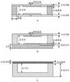
参见图2所示,图2中的A为人工心脏瓣膜支架1的主体区段中,靠近主体区段的流入端的部分区段的侧视图,图2中的B为人工心脏瓣膜支架1的主体区段中,靠近主体区段的流入端的部分区段的仰视图,如图2所示主体区段的流入端104设置有平台结构105,平台结构105伸向人工心脏瓣膜支架的内部,平台结构105与径向平行;结合图2和图5所示,平台结构105设置有用于检测心室总压的第三无源无线传感器13的第三电容式传感器130,第三电容式传感器130通过导线107与人工心脏瓣膜支架单一单元格内部的电感线圈连接。Referring to shown in Fig. 2, A among Fig. 2 is the side view of the partial section near the inflow end of the main body section in the main body section of the artificial
介入手术是治疗各种心血管相关疾病的可选方案,心血管相关疾病包括心脏瓣膜疾病。生物体如人体内的原生瓣膜(如主动脉瓣,肺动脉瓣,房室瓣等)对血液循环系统的运作起到至关重要的作用,如果患有先天或后天瓣膜疾病,例如主动脉二尖瓣或瓣膜钙化,可能导致瓣膜不能正常开闭,则会增加心脏负荷且影响对其他器官的供血。经导管瓣膜置换术(Transcatheter Valve Therapies,TVR)是一种针对心脏瓣膜疾病的治疗手段,通过导丝引导,将支架送至瓣膜区域并撑开原生瓣膜,由支架上带有的人工瓣膜代替原生瓣膜进行工作。这种方式避免了外科开胸手术,降低了治疗过程的创伤性,对一些年纪大或体力较弱的病人也适用。Interventional surgery is an option for the treatment of various cardiovascular-related diseases, including heart valve disease. Organisms such as the native valves in the human body (such as aortic valve, pulmonary valve, atrioventricular valve, etc.) play a vital role in the operation of the blood circulatory system. If you suffer from congenital or acquired valve diseases, such as aortic mitral Valve or valve calcification, which may cause the valve to not open and close normally, will increase the workload of the heart and affect the blood supply to other organs. Transcatheter Valve Therapies (TVR) is a treatment for heart valve diseases. Guided by a guide wire, the stent is sent to the valve area and the native valve is stretched, and the artificial valve on the stent replaces the native valve. valve to work. This method avoids surgical thoracotomy, reduces the trauma of the treatment process, and is also suitable for some elderly or weak patients.
人工瓣膜植入后,瓣膜跨壁压和瓣膜流量是主要监测的生理参数。传统监测方案中,瓣膜流量通过超声检查进行测量,瓣膜跨壁压则需要用压力导丝进行测量;两者都需要专业的测量设备和操作人员,需要病人到医院进行测量;且适用压力导丝测量跨壁压的耗时较长和经济成本较高。After artificial valve implantation, valve transmural pressure and valve flow are the main physiological parameters monitored. In the traditional monitoring scheme, the valve flow is measured by ultrasound, and the valve transmural pressure needs to be measured with a pressure guide wire; both require professional measurement equipment and operators, and the patient needs to go to the hospital for measurement; and a pressure guide wire is applicable Measuring the transwall pressure is time consuming and economically expensive.
本申请实施例中,本申请提供的人工心脏瓣膜支架,在单个人工心脏瓣膜支架上搭载多个无源无线传感器,可测量人工心脏瓣膜使用过程中瓣膜跨壁压和瓣膜流量;例如,上述第一无源无线传感器11用于检测主动脉静压,第二无源无线传感器12用于检测心室静压,主动脉内部静压和心室静压的差值为跨壁压;第三无源无线传感器13用于检测心室总压,心室总压和心室静压的差值为心室动压,心室动压用于转换为流量;本申请提供的第一无源无线传感器11、第二无源无线传感器12和第三无源无线传感器13,在较小的程度内影响人工心脏瓣膜支架的原有外形和功能,此外,还可以在人工心脏瓣膜支架上搭载多个传感器以测量瓣膜跨壁压或瓣膜流量。可见,本申请提供的人工心脏瓣膜支架,电路设计简单,省略了电源电线等装置,减少了植入物的体积和数量,提高安全性和适用性,同时对跨壁压和流量进行实时监测,获得的参数可辅助医生监测病人状态,可提前发现问题及进行干预。In the embodiment of the present application, the artificial heart valve stent provided by the present application is equipped with multiple passive wireless sensors on a single artificial heart valve stent, which can measure the valve transmural pressure and valve flow during the use of the artificial heart valve; for example, the above-mentioned A
上述的第一无源无线传感器11、第二无源无线传感器12和第三无源无线传感器13均包括基于谐振电路设计原理设计的电路,本申请所采用的谐振电路结构简单,在谐振电路上搭载电容式传感器或电阻式传感器,即可组成一个带传感器的简易天线,使用射频(radio frequency,RF)天线可与该简易天线通信,通过测量简易天线的共振频率或带宽,可获得谐振电路中传感器的电容值或电阻值,从而反推物理值且达到测量瓣膜跨壁压、瓣膜流量的目的。The above-mentioned first
本申请其他实施例中,在第一种可实现的方案中,参见图1所示,主体区段的流出端101具有固定结构1011,固定结构1011与轴向平行,固定结构1011设置有第一无源无线传感器11包括的第一电容式传感器110。In other embodiments of the present application, in the first possible solution, as shown in Figure 1, the
这里,以第一电容式传感器110设置在主体区段的流出端101为例,可选地,主体区段的流出端101设置有固定结构1011,固定结构1011设置有第一电容式传感器110,由于金属支架本身带有电感和电阻,以此支架本体与第一电容式传感器110共同组成第一无源无线传感器的一个测量电路;此时,第一电容式传感器110可以通过激光焊接或导电环氧树脂粘合剂等方式固定在固定结构1011上,从而形成一个RLC串联谐振电路。Here, taking the
需要说明的是,参见图1所示,在固定结构1011设置有第一电容式传感器110,第一电容式传感器110和支架本体组成第一无源无线传感器11的同时,还需要在主体区段的侧壁102上设置第二无源无线传感器12。固定结构1011用于将人工心脏瓣膜支架固定在输送系统上,控制人工心脏瓣膜支架的释放。人工心脏瓣膜支架可以是镍钛诺合金制作的自膨胀支架。It should be noted that, as shown in FIG. 1 , the fixed
本申请其他实施例中,图1中第二无源无线传感器12具有第一串联谐振电路,第一串联谐振电路包括在多个单元格的单一单元格内,参见图3所示,由第二电容式传感器120和导线(图3中在单元格内缠绕的线和/或在单元格的支架上缠绕的线都是导线)连接形成的电路。也就是说,组成第二无源无线传感器12的第一串联谐振电路可以设置在多个单元格的单一单元格内。In other embodiments of the present application, the second
本申请其他实施例中,参见图4所示,人工心脏瓣膜支架1还包括:In other embodiments of the present application, referring to Fig. 4, the prosthetic
裙边区段30,包覆在主体区段10的径向内外侧,且裙边区段30位于主体区段的流出端101和主体区段的流入端104之间;示例性的,图4中裙边区段30位于主体区段的底部,底部是指靠近主体区段的流入端104的方位。参见图4所示,主体区段10的一些区域有镂空的部分108,其位于主动脉一侧;镂空或增加该区域网格长度的目的是为了防止对冠脉介入手术造成阻碍。The
针对不同人工心脏瓣膜支架设计,镂空的部分108的位置可能有所变化;人工心脏瓣膜支架会的支架底部包覆一层裙边区段30,在本申请中,裙边区段30既可用作防止周漏,又可用作固定传感器;裙边区段30特指由裙边覆盖的区域。For different artificial heart valve stent designs, the position of the hollowed-out
在第二种可实现的方案中,提供了单一单元格内设置第一串联谐振电路的一种方案,图3中的第一种第一串联谐振电路201被固定在图4所示的裙边区段30上,如图3所示,第一种第一串联谐振电路201的结构为:单一单元格内导线环绕或缠绕形成电感,且在导线环绕的中间区域设置有第二电容式传感器120,导线的两端分别与第二电容式传感器120的电极连接,结合导线本身的电阻,形成RLC串联电路;该方案中,可以通过调整电感环绕的半径,圈数等参数来调节电感值,从而调节RLC串联电路的工作频率范围。In the second achievable solution, a solution of setting the first series resonant circuit in a single cell is provided, and the first series
本申请其他实施例中,在第三种可实现的方案中,提供了单一单元格内设置第一串联谐振电路的另一种方案,图3中的第二种第一串联谐振电路202、第三种第一串联谐振电路203、第四种第一串联谐振电路204的结构为:导线缠绕在单一单元格的至少一条支撑杆上形成螺旋电感线圈,或者,导线在一个单元格内形成多匝环形线圈电感,导线的两端分别与第二电容式传感器120的电极连接。其中,图3中的第二种第一串联谐振电路202的结构为:导线缠绕在单一单元格的一条支撑杆上形成电感线圈,导线的两端分别与第二电容式传感器120的电极连接。图3中的第三种第一串联谐振电路203的结构为:导线缠绕在单一单元格的二条支撑杆上形成电感线圈,导线的两端分别与第二电容式传感器120的电极连接。图3中的第四种第一串联谐振电路204的结构为:导线缠绕在单一单元格的三条支撑杆上形成电感线圈,导线的两端分别与第二电容式传感器120的电极连接。可见,在第三种可实现的方案中,在一个网格内,导线缠绕网格边界,即人工心脏瓣膜支架的支撑杆,形成线圈。导线的两端分别与第二电容式传感器120的电极相连接,结合导线本身的电阻,形成RLC串联电路。需要说明的是,在实际应用中,根据所需电感值大小,可选择缠绕1到3条支撑杆;另外,该方案中,可以通过调整导线缠绕圈数,螺距等参数,调整电感值,从而调节RLC串联电路的工作频率范围。In other embodiments of the present application, in the third possible solution, another solution for setting the first series resonant circuit in a single cell is provided. The second type of first series
本申请其他实施例中,图1中第二无源无线传感器12具有第一串联谐振电路,第一串联谐振电路设置在相邻两个单元格内,参见图3所示,第一无源无线传感器具有第一串联谐振电路,第一串联谐振电路包括在多个单元格的相邻的两个单元格内。In other embodiments of the present application, the second
进一步地,本申请其他实施例中,在第四种可实现的方案中,提供了相邻两个单元格内设置第一串联谐振电路的一种方案,图3中的第五种第一串联谐振电路205的结构为:导线环绕设置在相邻的两个单元格中的一个单元格内,第二电容式传感器120设置在相邻的两个单元格中的另一个单元格内,导线的两端分别与第二电容式传感器120的电极连接。参见图3中的第五种第一串联谐振电路205所示,RLC串联电路放置在人工心脏瓣膜支架的底部区域,第二电容式传感器120放置在与导线环绕形成的线圈所在网格的相邻的另一个网格内。Furthermore, in other embodiments of the present application, in the fourth possible solution, a solution is provided in which the first series resonant circuit is arranged in two adjacent cells, the fifth first series resonant circuit in Figure 3 The structure of the
进一步地,本申请其他实施例中,在第五种可实现的方案中,提供了相邻两个单元格内设置第一串联谐振电路的一种方案,图3中的第六种第一串联谐振电路206的结构为:导线缠绕在相邻的两个单元格同一侧的支撑杆上形成两个电感线圈,两个电感线圈的一端通过电阻式传感器22连接,两个电感线圈的另一端通过定值电容23连接。参见图3中的第六种第一串联谐振电路206所示,RLC串联电路放置在人工心脏瓣膜支架的底部区域,在第五种可实现的方案中,传感器类型为电阻式传感器22,搭配一个定值电容23;因为电路中配置了电阻式传感器和定值电容,本方案的电路设置在两个相邻的网格内。导线缠绕两个网格同一侧的支撑杆,形成电感线圈;使用两个线圈连接电阻式传感器和定值电容,最终形成RLC串联电路。调整导线缠绕圈数,螺距等参数,或者调整定值电容23的电容值均可控制电路的共振频率,从而调节RLC串联电路的工作频率范围Furthermore, in other embodiments of the present application, in the fifth achievable solution, a solution is provided in which the first series resonant circuit is arranged in two adjacent cells. The sixth first series resonant circuit in Fig. 3 The structure of the
本申请其他实施例中,图2所示主体区段的流入端104设置有平台结构105,图2中的平台结构105底部设置有用于检测心室总压的第三无源无线传感器13。结合图5所示,第三无源无线传感器13具有第二串联谐振电路,第二串联谐振电路包括第三电容式传感器130,以及在多个单元格的单一单元格内和/或单一单元格的支撑杆上绕制导线形成的电感,导线的两端与第三电容式传感器130的电极连接。In other embodiments of the present application, the
结合图2、图5和图6所示,底层网格下方添加了一个平台结构105;平台结构105伸向人工心脏瓣膜支架内部,将第三电容式传感器130用激光焊接或环氧树脂粘合剂等方式固定在平台结构105底部;然而第三电容式传感器130并不与人工心脏瓣膜支架形成回路,因此,从第三电容式传感器130引出两条导线;并使用导线在网格内部或网格支撑杆上绕制电感元件。As shown in Fig. 2, Fig. 5 and Fig. 6, a
进一步地,本申请其他实施例中,在第六种可实现的方案中,图6中的A为导线在网格内部环绕形成电感,电感与平台结构105底部的第三电容式传感器130引出的导线107连接,形成RLC串联电路;通过调整导线缠绕圈数,螺距等参数,可调节RLC串联电路的工作频率范围。Furthermore, in other embodiments of the present application, in the sixth achievable solution, A in FIG. 6 is a wire looping inside the grid to form an inductance, and the inductance is connected to the third
进一步地,本申请其他实施例中,在第七种可实现的方案中,图6中的B为导线在环绕网格支撑杆形成电感,电感与平台结构105底部的第三电容式传感器130引出的导线连接,形成RLC串联电路;通过调整导线缠绕圈数,螺距等参数,可调节RLC串联电路的工作频率范围。Furthermore, in other embodiments of the present application, in the seventh possible solution, B in FIG. 6 is that the wire forms an inductance around the grid support rod, and the inductance is drawn out from the third
进一步地,本申请其他实施例中,在第八种可实现的方案中,图6中的C结合了图6中的A和图6中的B导线绕制方式形成电感,电感与电容式传感器引出的导线连接,形成RLC串联电路;通过调整导线缠绕圈数,螺距等参数,可调节RLC串联电路的工作频率范围。Further, in other embodiments of the present application, in the eighth achievable solution, C in FIG. 6 combines A in FIG. 6 and B in FIG. 6 to form an inductance, an inductance and a capacitive sensor The lead wires are connected to form an RLC series circuit; the operating frequency range of the RLC series circuit can be adjusted by adjusting parameters such as the number of wire winding turns and pitch.
需要说明的是,图5中第三无源无线传感器13为了便于描述,所以标注在平台结构105上,可以理解的,第三无源无线传感器13包括图5中平台结构105上的第三电容式传感器130、两根导线107、以及图6中多个单元格的单一单元格内和/或单一单元格的支撑杆上绕制导线形成的电感。It should be noted that the third
进一步地,针对搭载在上述人工心脏瓣膜支架上的电容式传感器和电阻式传感器的工作原理以及构造进行说明,Further, the working principle and structure of the capacitive sensor and resistive sensor mounted on the above-mentioned artificial heart valve stent will be described,
本申请中用到的电容式传感器,可以是平行板电容,电极附着在薄膜上,体内血压的变化使薄膜发生形变且改变平行板之间的距离,导致电容值改变从而影响RLC串联电路的共振频率;通过测量电路的共振频率,即可反推血压值。其中电容的计算公式为:The capacitive sensor used in this application can be a parallel plate capacitor, and the electrode is attached to the film. The change of blood pressure in the body will deform the film and change the distance between the parallel plates, resulting in a change in capacitance value and affecting the resonance of the RLC series circuit. Frequency; by measuring the resonant frequency of the circuit, the blood pressure value can be reversed. The formula for calculating the capacitance is:

其中,C为电容值,P为血压值,ε为真空中介电常数,A为平行板的面积,d为平行板之间的距离,d随着血压变化而变化。Among them, C is the capacitance value, P is the blood pressure value, ε is the dielectric constant in vacuum, A is the area of the parallel plates, d is the distance between the parallel plates, and d changes with the blood pressure.
下面介绍可能使用的电容构造以及工作原理:The following describes possible capacitor configurations and how they work:
构造一:构造一的剖面图如图7中的A所示,中空的基底被两片薄膜夹在中间,活动薄膜表面有一层金属薄膜作为电极;活动薄膜受血压影响发生形变,改变金属薄膜之间的距离,从而改变电容值。基底的材料可选择二氧化硅如玻璃,使用离子反应刻蚀技术制造中空区域。活动薄膜选择硅片来制作,使用光刻蚀技术在硅片表面刻蚀出接线电极电路;然后使用金属溅射技术,使导电金属填满刻蚀电路并在表面形成一层金属薄膜,作为电极。在真空环境下,将两片带有电极的硅片和中空的基底进行高温键合,形成真空密封腔且金属薄膜朝内。键合后使用化学腐蚀技术对两侧带有电极的硅片进行腐蚀直到接线电极的位置,并得到硅薄膜。完成腐蚀后进行晶片切割和封装,并将接线电极与上述第二种可实现的方案至第四种可实现的方案,或第六种可实现的方案至第八种可实现的方案中的线圈进行焊接,形成回路。其中接线电极的电路可根据具体的接线方案进行设计,以方便与线圈的焊接。Structure 1: The cross-sectional view of
构造二:构造二的剖面图如图7中的B所示,基底表面有一层金属薄膜电极,基底上方覆盖带有电极的活动薄膜,活动薄膜受血压影响发生形变,改变金属薄膜之间的距离,从而改变电容值。基底的材料可选择二氧化硅如玻璃,使用离子反应刻蚀技术,刻蚀出接线电极电路;然后使用金属溅射技术,在基底表面形成金属薄膜和接线电极。活动薄膜选择硅片来制作,使用光刻蚀技术在硅片上刻蚀出腔体和接线电极电路;然后使用金属溅射技术,形成接线电极和金属薄膜。在真空环境下,将硅片和基底进行高温键合,形成真空密封腔且金属薄膜朝内。键合后使用化学腐蚀技术对硅片进行腐蚀直到接线电极的位置,并得到硅薄膜。完成腐蚀后进行晶片切割和封装,并将接线电极与上述第二种可实现的方案至第四种可实现的方案,或第六种可实现的方案至第八种可实现的方案中的线圈进行焊接,形成回路。其中接线电极的电路可根据具体的接线方案进行设计,以方便与线圈的焊接。Structure 2: The cross-sectional view of
构造三:构造三的剖面图如图7中的C所示,使用金属材料作为基底,基底上方覆盖一层活动薄膜,活动薄膜上又覆盖一层金属薄膜作为电极。基底的材料为可导电金属,而且是可应用于手术植入器材的金属材料,采用微放电加工技术或激光加工技术,在金属基底上刻出空腔。用聚酰亚胺作为活动薄膜,同时作为绝缘介质。使用电子束蒸发金属层,然后旋涂并固化在聚酰亚胺薄膜上,从而制作金属薄膜;或者直接使用金属溅射技术在聚酰亚胺形成金属薄膜。在真空环境下加热,并使聚酰亚胺薄膜键合到金属基底上,形成真空密封腔。构造三的电容用于第一种可实现的方案,通过将金属基底焊接在固定结构1011上,可直接与支架形成RLC回路。Structure 3: The cross-sectional view of structure 3 is shown as C in Figure 7. Metal material is used as the base, a layer of active film is covered on the base, and a layer of metal film is covered on the active film as an electrode. The material of the base is conductive metal, and is a metal material that can be applied to surgical implantation equipment, and a cavity is carved on the metal base by using a micro-discharge processing technology or a laser processing technology. Polyimide is used as the active film and at the same time as the insulating medium. The metal layer is evaporated by electron beam, then spin-coated and cured on the polyimide film to make a metal film; or directly use metal sputtering technology to form a metal film on polyimide. Heating in a vacuum environment and bonding the polyimide film to the metal substrate to form a vacuum-sealed cavity. The capacitor in the third structure is used in the first possible solution, by welding the metal base to the fixed
本申请的第五种可实现的方案是一种使用电阻式传感器的方案,其工作原理是硅、锗等半导体具有压阻效应,在发生形变的情况下,其电阻会产生相应的变化,电阻随压力变化的表达式为:The fifth achievable solution of this application is a solution using a resistive sensor. Its working principle is that semiconductors such as silicon and germanium have a piezoresistive effect. In the case of deformation, their resistance will change accordingly. The expression that varies with pressure is:

其中,R为电阻值;ΔR为电阻的变化值;πl,πt分别是纵向和横向的压阻系数;σl(P),σt(P)分别是纵向和横向的应力,σl(P),σt(P)随着血压变化而变化。Among them, R is the resistance value; ΔR is the change value of resistance; πl , πt are the longitudinal and transverse piezoresistive coefficients respectively; σl (P), σt (P) are the longitudinal and transverse stresses respectively, σl (P), σt (P) changes with blood pressure.
在第五种可实现的方案中,电阻式传感器因血压变化产生形变,从而改变RLC串联电路的电阻值以及RLC串联电路的带宽;测量带宽则可以反推电阻值和血压值。其中电阻式传感器的构造如图8所示,在基底上方有一片真空腔体和一块活动薄膜,活动薄膜由半导体制成,在血压下发生形变时其电阻值发生改变。选择硅片,通过掺入微量元素,如磷,硼等改善导电性能;使用化学腐蚀技术,在硅片上腐蚀出腔体并形成活动薄膜;选择玻璃为基底,在真空环境下将硅片与玻璃基底进行高温键合,形成真空密闭腔体。硅片掺入微量元素后具有导电性,导线与硅片连接即可形成回路。In the fifth achievable solution, the resistance sensor is deformed due to the change of blood pressure, thereby changing the resistance value of the RLC series circuit and the bandwidth of the RLC series circuit; the measurement bandwidth can reverse the resistance value and blood pressure value. The structure of the resistive sensor is shown in Figure 8. There is a vacuum cavity and a movable film above the substrate. The movable film is made of semiconductor, and its resistance value changes when it deforms under blood pressure. Select silicon wafers, improve electrical conductivity by doping trace elements, such as phosphorus, boron, etc.; use chemical etching technology to etch out cavities on silicon wafers and form active films; choose glass as the substrate, and combine silicon wafers with The glass substrates are bonded at high temperature to form a vacuum-tight cavity. The silicon chip has conductivity after being doped with trace elements, and the wire can be connected with the silicon chip to form a circuit.
本申请的第二种可实现的方案到第八种可实现的方案中,导线是RLC串联电路的主要电阻来源。已知电阻越小,RLC串联电路的带宽越小,更容易分辨电路的共振频率,提高测量精度。金,银的电导率高,本申请人考虑到导线强度问题,可能不适合制作导线,因此可以采用金属镀层工艺或金属喷涂工艺,在强度高的导线上覆盖一层金或银的薄膜,以此提高电导率。本申请的其中一个特点是可放置多个传感器,因此需要考虑第一种可实现的方案与其他方案共同应用在一个支架上的情况。为了防止其他方案的线圈或导线与支架接触且形成回路,可在以上导线或线圈表面添加绝缘涂料涂层,如聚四氟乙烯等材料,从而减小线圈或导线对支架的电感和电阻的影响,保证第一种可实现的方案正常工作。理想的情况下,导线在覆盖金属涂层以提高电导率后,再添加一层绝缘涂料;考虑到经济成本且电路带宽已经足够小的情况下,可只在导线表面添加绝缘涂料。In the second to eighth possible solutions of the present application, the wire is the main resistance source of the RLC series circuit. It is known that the smaller the resistance, the smaller the bandwidth of the RLC series circuit, and it is easier to distinguish the resonant frequency of the circuit and improve the measurement accuracy. Gold and silver have high electrical conductivity, and the applicant may not be suitable for making wires in consideration of the strength of the wires. Therefore, a metal plating process or a metal spraying process can be used to cover a high-strength wire with a thin film of gold or silver. This increases conductivity. One of the characteristics of this application is that multiple sensors can be placed, so it is necessary to consider the situation that the first achievable solution is applied together with other solutions on a bracket. In order to prevent the coils or wires of other schemes from contacting the stent and forming a loop, an insulating paint coating, such as polytetrafluoroethylene, can be added to the surface of the above wires or coils to reduce the influence of the coil or wire on the inductance and resistance of the stent , to ensure that the first achievable solution works properly. Ideally, after the wire is covered with a metal coating to improve conductivity, a layer of insulating paint is added; considering the economic cost and the circuit bandwidth is small enough, only the insulating paint can be added to the surface of the wire.
本申请中,RLC串联电路的两个特征参数被用于测量物理值,分别是共振频率和带宽。共振频率f0的表达式为:
带宽Δf的表达式为:
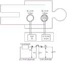
如图9所示,支架植入后,可通过第一外部天线41与支架上的无源无线传感器进行交流,从而测量人体内部的生理参数。第一外部天线41为射频天线,实际上是电感线圈,以图9所示的线圈为为例,实际形状可根据实际场景的具体情况进行设计。电源42为第一外部天线41提供不同频率的电流或电压,使得射频天线附近产生交变电磁场;支架上搭载的电感在交变电磁场的作用下产生电流,并吸收交变电磁场的能量。图9展示了外部天线电路和内部传感器电路。其中,La是外部天线的电感,Ls是上述方案中的线圈电感或支架本身的电感,Lm是La和Ls耦合时产生的互感电感;Rs是上述方案中线圈的电阻、支架本身的电阻或电阻式传感器的电阻;Cs是上述方案中电容式传感器的电容或定值电容。Va是La两侧的电压,Vs是Ls两侧的电压,Ia是流经La的电流,Is是流经Ls的电流。根据互感耦合电路的特性可以得到:As shown in FIG. 9 , after the stent is implanted, the first external antenna 41 can communicate with the passive wireless sensor on the stent to measure physiological parameters inside the human body. The first external antenna 41 is a radio frequency antenna, which is actually an inductive coil. Taking the coil shown in FIG. 9 as an example, the actual shape can be designed according to the specific conditions of the actual scene. The
Va=sLaIa+sLmIs(1)Va =sLa Ia +sLm Is (1)
Vs=sLmIa+sLsIs(2)Vs =sLm Ia +sLs Is (2)
其中,s=j·2π·f,j2=-1,f为频率。根据RLC串联电路的特性,可以得到:Wherein, s=j·2π·f, j2 =-1, and f is the frequency. According to the characteristics of the RLC series circuit, it can be obtained:

联立公式(1)-(2),可得到Va与Ia之间的关系式:By combining formulas (1)-(2), the relationship between Va and Ia can be obtained:

因此,外部天线的电感线圈的输入阻抗Z等于:Therefore, the input impedance Z of the inductor coil of the external antenna is equal to:

其中,k为互感耦合参数,Q为质量因素,其表达式为:Among them, k is the mutual inductance coupling parameter, Q is the quality factor, and its expression is:


输入阻抗Z是一个复数,Z的辐角反映了电流与电压之间的相位差,相位差随着频率变化而变化;对公式(5)进行求导分析可发现,相位差随着频率的变化有极小值且对应的频率是共振频率f0,如图10所示;因此,通过测量输入阻抗Z关于频率f的变化,就可以提取出共振频率f0。根据输入阻抗辐角与频率的关系,将外部天线电路与阻抗分析仪连接,提取出不同频率下的相位差并进行拟合,根据拟合结果能得出f0,k和Q值,其中f0和Q值可分别用于测量电容式传感器和电阻式传感器的参数。因此,本申请可以选择以阻抗分析的方式进行信号分析,这时图9中的信号分析系统43为阻抗分析仪和计算机,通过阻抗分析仪获得阻抗信息后,在计算机中进行拟合,提取共振频率和带宽。The input impedance Z is a complex number, and the argument of Z reflects the phase difference between the current and the voltage, and the phase difference changes with the frequency; the derivative analysis of formula (5) shows that the phase difference changes with the frequency There is a minimum value and the corresponding frequency is the resonant frequency f0 , as shown in Figure 10; therefore, the resonant frequency f0 can be extracted by measuring the variation of the input impedance Z with respect to the frequency f. According to the relationship between the input impedance argument and frequency, connect the external antenna circuit to the impedance analyzer, extract the phase difference at different frequencies and perform fitting, and f0 , k and Q values can be obtained according to the fitting results, where fThe 0 and Q values can be used to measure parameters of capacitive and resistive sensors, respectively. Therefore, the present application can choose to perform signal analysis in the form of impedance analysis. At this time, the signal analysis system 43 in FIG. frequency and bandwidth.
上述提到内部传感器电路在交变电磁场下吸收外部天线的能量从而产生电流;在撤走外部天线后,电流仍然存在且在电阻的作用下逐渐衰减。在电流消失前,传感器电路会产生交变电磁场,对该电磁场进行分析也能获得传感器电路的特征参数。如图11所示,在使用第三外部天线45对无源无线传感器进行激励后,断开电源并将第二外部天线44靠近传感器。第二外部天线44实际上也是电感线圈,在传感器产生的交变电磁场作用下,第二外部天线44从交变电场吸收能量并在内部产生电流。传感器电路在共振频率下吸收和释放的能量的功率都是最高的;测量第二外部天线44的电压和电流并换算为电功率,记录电功率随着频率的变化,最大电功率对应的频率就是共振频率。图12展示了第二外部天线44的功率变化曲线,频率等于共振频率f0时功率达到最大值;另外,在功率下降到最大功率一半时对应了两个频率,这两个频率的差值就是带宽Δf。在这种方案中,第二外部天线44连接的信号分析系统可以选择示波器和计算机,记录电压,电流和电功率数据后在计算机中进行傅里叶变换,计算出各种频率的电功率,然后再提取出共振频率和带宽。As mentioned above, the internal sensor circuit absorbs the energy of the external antenna under the alternating electromagnetic field to generate current; after the external antenna is removed, the current still exists and gradually decays under the action of resistance. Before the current disappears, the sensor circuit will generate an alternating electromagnetic field, and analyzing the electromagnetic field can also obtain the characteristic parameters of the sensor circuit. After energizing the passive wireless sensor with the third external antenna 45 as shown in FIG. 11 , the power is removed and the second external antenna 44 is brought close to the sensor. The second external antenna 44 is actually an inductance coil. Under the action of the alternating electromagnetic field generated by the sensor, the second external antenna 44 absorbs energy from the alternating electric field and generates current inside. The power of energy absorbed and released by the sensor circuit at the resonant frequency is the highest; the voltage and current of the second external antenna 44 are measured and converted into electric power, and the variation of electric power with frequency is recorded, and the frequency corresponding to the maximum electric power is the resonant frequency. Fig. 12 has shown the power change curve of the second external antenna 44, and the power reaches the maximum when the frequency is equal to the resonant frequency f0 ; in addition, when the power drops to half of the maximum power, it corresponds to two frequencies, and the difference between these two frequencies is Bandwidth Δf. In this scheme, the signal analysis system connected to the second external antenna 44 can choose an oscilloscope and a computer, and after recording voltage, current and electric power data, perform Fourier transform in the computer to calculate the electric power of various frequencies, and then extract out the resonant frequency and bandwidth.
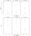
RLC串联电路具有带通滤波的特性,吸收或释放一定频率范围内的能量,在该频率范围内外,其吸收或释放的能量很小,电流和电压的相位差也接近90度,图10和图12都反映了这种现象。因此,可以利用RLC串联电路这种带通特性,进行多个传感器的测量,如图13所示。确定传感器的压力测量范围后,通过调整电容值或电感值,使得传感器的共振频率在一定频率范围内变化,该频率范围称作工作范围。在对传感器进行信号分析时,只需要在对应的工作范围内读取共振频率或带宽,可保证多个传感器同时工作时不会互相影响。The RLC series circuit has the characteristics of band-pass filtering, which absorbs or releases energy within a certain frequency range. Inside and outside this frequency range, the absorbed or released energy is very small, and the phase difference between the current and voltage is also close to 90 degrees, as shown in Figure 10 and Figure 10. 12 all reflect this phenomenon. Therefore, the band-pass characteristic of the RLC series circuit can be used to measure multiple sensors, as shown in Figure 13. After the pressure measurement range of the sensor is determined, the resonant frequency of the sensor changes within a certain frequency range by adjusting the capacitance or inductance value, which is called the working range. When analyzing the signal of the sensor, it is only necessary to read the resonant frequency or bandwidth within the corresponding working range, which can ensure that multiple sensors will not affect each other when they work at the same time.
参考图3中的电感绕制方案,本申请中的电感可归类为螺旋线圈电感(如图3中202-204,图3中306和图6中的B)或多匝环形线圈电感(如图3中201,图3中205和图6中的A),图6中的C则可以认为是两种电感的串联。如上文所说,通过调整电感值可调节电路的工作范围,从而实现多个传感器工作方案,其中电感的调节方式包括控制电感圈数,电线长度,线圈面积等参数。针对螺旋线圈电感,其电感值的计算公式如下:With reference to the inductance winding scheme in Fig. 3, the inductance among the present application can be classified as helical coil inductance (such as 202-204 among Fig. 3, 306 among Fig. 3 and B among Fig. 6) or multi-turn toroidal coil inductance (such as 201 in FIG. 3 , 205 in FIG. 3 and A) in FIG. 6 , and C in FIG. 6 can be considered as a series connection of two inductors. As mentioned above, the working range of the circuit can be adjusted by adjusting the inductance value, so as to realize multiple sensor working schemes. The adjustment method of the inductance includes controlling parameters such as the number of inductance turns, the length of the wire, and the area of the coil. For the helical coil inductance, the calculation formula of its inductance value is as follows:

其中,μr为相对磁导率,μ0为真空磁导率,N为线圈圈数,Area为线圈截面积,l为线圈长度。Among them, μr is the relative magnetic permeability, μ0 is the vacuum magnetic permeability, N is the number of coil turns, Area is the cross-sectional area of the coil, and l is the length of the coil.
针对多匝环形线圈电感,其电感值的计算公式如下:For the multi-turn toroidal coil inductance, the calculation formula of its inductance value is as follows:

davg=0.5·(Dout+Din)davg =0.5·(Dout +Din )
ρ=(Dout-Din)/(Dout+Din)ρ=(Dout -Din )/(Dout +Din )
其中,davg为线圈外径Dout和线圈内径Din的平均值,ρ为填充比,c1,c2,c3,c4都是常数,分别等于1.0,2.46,0.0,0.20。图14提供了两种电感的绕线方式,图14中的A为螺旋线圈电感,图14中的B为多匝环形线圈电感。图14中的B中,w为导线直径,s为导线之间的间隙,线圈圈数N由线圈外径Dout,线圈内径Din,导线直径w和导线之间的间隙s决定。Among them, davg is the average value of coil outer diameter Dout and coil inner diameter Din , ρ is filling ratio, c1 , c2 , c3 , and c4 are all constants, equal to 1.0, 2.46, 0.0, 0.20 respectively. Figure 14 provides two winding methods of inductors, A in Figure 14 is a helical coil inductor, and B in Figure 14 is a multi-turn toroidal coil inductor. In B in Fig. 14, w is the diameter of the wire, s is the gap between the wires, and the number of coil turns N is determined by the outer diameter Dout of the coil, the inner diameter Din of the coil, the diameter w of the wire and the gap s between the wires.
在第一种实际应用场景中,使用上述的传感器搭载方案和测量方式,实现测量瓣膜跨壁压的功能,如图2所示。为了测量主动脉内部的压力,采用第一种可实现的方案在主动脉一侧放置一个传感器电路,传感器的构造参考图7中的C;为了测量心室的压力,采用第二种可实现的方案在支架底部网格内搭载一个RLC串联电路,其中传感器的构造参考图7中的A或图7中的B;在实际操作中,第二种可实现的方案可替换为第三种可实现的方案、第四种可实现的方案或第五种可实现的方案。利用裙边区段30包裹支架底部的网格以及RLC串联电路,使RLC串联电路固定在网格内,且避免电路与血液直接接触。In the first practical application scenario, the above-mentioned sensor mounting scheme and measurement method are used to realize the function of measuring valve transmural pressure, as shown in FIG. 2 . In order to measure the pressure inside the aorta, a sensor circuit is placed on the side of the aorta using the first feasible scheme. The structure of the sensor refers to C in Figure 7; in order to measure the pressure of the ventricle, the second feasible scheme is adopted An RLC series circuit is installed in the grid at the bottom of the bracket, and the structure of the sensor refers to A in Figure 7 or B in Figure 7; in actual operation, the second achievable solution can be replaced by the third achievable option, the fourth achievable option, or the fifth achievable option. The
进行压力测量时,将外部天线靠近心脏区域,启动电源,电源提供的电流或电压频率覆盖两个传感器电路的工作范围,使外部天线内部产生交变电磁场并对传感器电路产生激励。借助信号分析系统,在两个传感器电路各自的工作范围内搜索对应的共振频率如图13所示,转换成压力数据,获得跨瓣压值。When performing pressure measurement, put the external antenna close to the heart area, start the power supply, and the current or voltage frequency provided by the power supply covers the working range of the two sensor circuits, so that an alternating electromagnetic field is generated inside the external antenna and excites the sensor circuit. With the help of the signal analysis system, search for the corresponding resonance frequency within the respective working ranges of the two sensor circuits, as shown in Figure 13, convert it into pressure data, and obtain the transvalvular pressure value.
在第二种实际应用场景中,使用上述的传感器搭载方案和测量方式,实现测量瓣膜跨壁压的功能,如图15所示,支架放置在心窦附近,两个传感器分别测量心室和主动脉的压力,心室一侧的传感器是电阻式传感器。为了测量主动脉内部的压力,采用第一种可实现的方案在主动脉一侧放置一个传感器电路,传感器的构造参考图7中的C;为了测量心室的压力,采用第五种可实现的方案在支架底部网格内搭载一个RLC串联电路,其中传感器的构造参考图8。利用裙边区段30包裹支架底部的网格以及RLC串联电路,使RLC串联电路固定在网格内,且避免电路与血液直接接触。In the second practical application scenario, the above-mentioned sensor mounting scheme and measurement method are used to realize the function of measuring valve transmural pressure. As shown in Figure 15, the stent is placed near the cardiac sinus, and the two sensors measure the pressure of the ventricle and aorta respectively. Pressure, the sensor on the ventricular side is a resistive sensor. In order to measure the pressure inside the aorta, a sensor circuit is placed on the side of the aorta using the first possible solution. The structure of the sensor refers to C in Figure 7; in order to measure the pressure of the ventricle, the fifth possible solution is adopted An RLC series circuit is installed in the grid at the bottom of the bracket, and the structure of the sensor is shown in Figure 8. The
进行压力测量时,将外部天线靠近心脏区域,启动电源,电源提供的电流或电压频率覆盖两个传感器电路的工作范围,使外部天线内部产生交变电磁场并对传感器电路产生激励。借助信号分析系统,在电容式传感器电路的工作范围内搜索对应的共振频率,在电阻式传感器的工作范围内读取带宽,分别将共振频率和带宽转换成电容值和电阻值,进一步地获得主动脉压力和心室压力,两者作差计算跨瓣压。When performing pressure measurement, put the external antenna close to the heart area, start the power supply, and the current or voltage frequency provided by the power supply covers the working range of the two sensor circuits, so that an alternating electromagnetic field is generated inside the external antenna and excites the sensor circuit. With the help of the signal analysis system, search for the corresponding resonant frequency within the working range of the capacitive sensor circuit, read the bandwidth within the working range of the resistive sensor, convert the resonant frequency and bandwidth into capacitance and resistance values respectively, and further obtain the main Arterial pressure and ventricular pressure, the difference between the two to calculate the transvalvular pressure.
在第三种实际应用场景中,使用上述的传感器搭载方案和测量方式,实现测量流速的功能。其中一个测量血液静压,采用第二种可实现的方案在网格内部放置一个传感器电路,传感器构造参考图7中的A或图7中的B;另一个用于测量血液总压,采用第六种可实现的方案,在底部平台放置一个电容式传感器,传感器构造参考图7中的A或图7中的B,并于网格内的线圈组成电路。其中,第二种可实现的方案可以用第三种可实现的方案,第四种可实现的方案或第五种可实现的方案代替;第六种可实现的方案可以用第七种可实现的方案或第八种可实现的方案代替。利用裙边区段30包裹支架底部的网格以及RLC串联电路,使RLC串联电路固定在网格内,且避免电路与血液直接接触。血液冲击平台底部的传感器,血液在传感器的表面停止,此时动压转换成静压并作用在传感器的活动薄膜上,因此平台底部测量的压力时血液的总压;而放置在网格内的传感器没有受血流正面冲击,因此测量的是静压。总压Ptotal,静压Pstatic和动压Pdynamic的关系式如下:In the third practical application scenario, the above-mentioned sensor mounting scheme and measurement method are used to realize the function of measuring flow velocity. One of them measures blood static pressure, adopting the second achievable solution to place a sensor circuit inside the grid, and the sensor structure refers to A in Figure 7 or B in Figure 7; the other is used to measure blood total pressure, adopting the first Six achievable solutions, place a capacitive sensor on the bottom platform, refer to A in Figure 7 or B in Figure 7 for the structure of the sensor, and form a circuit with the coil in the grid. Among them, the second achievable scheme can be replaced by the third achievable scheme, the fourth achievable scheme or the fifth achievable scheme; the sixth achievable scheme can be replaced by the seventh achievable scheme option or the eighth achievable alternative. The
Ptotal=Pstatic+Pdynamic,
进行测量时,将外部天线靠近心脏区域,启动电源,电源提供的电流或电压频率覆盖两个传感器电路的工作范围,使外部天线内部产生交变电磁场并对传感器电路产生激励。借助信号分析系统,在两个传感器电路各自的工作范围内搜索对应的共振频率,参考图11所示,转换成压力数据并计算两侧的压力差,获得动压值。然后根据公式(8),计算血液速度v;这里ρ是血液的密度值,不同人的血液密度有差异,这里给出参考值为1060kg/m3。获得速度值后,可以借助医疗影像,如电子计算机断层扫描(Computed Tomography,CT)等,计算心室出口的面积,从而换算为流量数据。When measuring, put the external antenna close to the heart area, start the power supply, and the current or voltage frequency provided by the power supply covers the working range of the two sensor circuits, so that the external antenna generates an alternating electromagnetic field and excites the sensor circuit. With the help of the signal analysis system, search for the corresponding resonance frequency within the respective working ranges of the two sensor circuits, refer to Figure 11, convert it into pressure data and calculate the pressure difference on both sides to obtain the dynamic pressure value. Then according to the formula (8), calculate the blood velocity v; here ρ is the density value of the blood, the blood density of different people is different, the reference value given here is 1060kg/m3. After the velocity value is obtained, the area of the outlet of the ventricle can be calculated with the help of medical images, such as computerized tomography (CT), and converted into flow data.
在第四种实际应用场景中,在同一个支架内设置三个传感器电路,用于计算跨瓣压和流速,具体方案如图1所示,三个传感器一个放置在底部网格内,一个放置在底部平台下,一个在主动脉一侧。图1结合了第一种实际应用场景和第三种实际应用场景,使用第一种可实现的方案,第二种可实现的方案和第六种可实现的方案在支架上放置了三个传感器,分别用于测量主动脉静压,心室静压和心室总压。第二种可实现的方案可以用第三种可实现的方案至第五种可实现的方案代替,第六种可实现的方案可以用第七种可实现的方案、第八种可实现的方案代替。利用裙边区段30包裹支架底部的RLC串联电路,固定RLC串联电路,且避免电路与血液直接接触。参考第一种实际应用场景和第二种实际应用场景的操作方式,测量跨瓣压;参考第三种实际应用场景的方式,测量心室出口附近的流速。In the fourth practical application scenario, three sensor circuits are set in the same bracket to calculate the transvalvular pressure and flow velocity. The specific scheme is shown in Figure 1. One of the three sensors is placed in the bottom grid, and the other One under the bottom platform and one on the side of the aorta. Figure 1 combines the first practical application scenario and the third practical application scenario, using the first achievable solution, the second achievable solution and the sixth achievable solution to place three sensors on the bracket , respectively for the measurement of aortic static pressure, ventricular static pressure and total ventricular pressure. The second achievable scheme can be replaced by the third to fifth achievable schemes, the sixth achievable scheme can be replaced by the seventh achievable scheme, the eighth achievable scheme replace. The
本申请提供的人工心脏瓣膜支架,具有如下有益效果:人体的心动周期为0.8s左右,因此人体血压或流量的变化频率为1-2Hz;只要RLC串联电路的电流电压频率远高于血压的变化频率,可在血压发生明显变化前就测量出某一时刻的血压值。因此可以通过将RLC串联电路的工作频率范围设置为远高于2Hz,就能获得一个心动周期内每个时刻对应的压力值。因此本申请在无需压力导丝等介入类器材的情况下也实时能检测瓣膜附近的压力变化。本申请采用无源无线传感器的设计,电路设计简单,省略了电源电线等装置,减少了植入物的体积和数量,提高安全性和适用性。本申请设置了单个支架搭载多个传感器的方案,可测量人工心脏瓣膜使用过程中主要关注参数:跨瓣压和流量。本申请可对瓣膜跨壁压和瓣膜流量进行实时监测,获得参数可辅助医生进行监测病人状态,可提前发现问题及进行干预。The artificial heart valve stent provided by this application has the following beneficial effects: the cardiac cycle of the human body is about 0.8s, so the change frequency of the blood pressure or flow of the human body is 1-2Hz; as long as the current and voltage frequency of the RLC series circuit is much higher than the change of blood pressure The frequency can measure the blood pressure value at a certain moment before the blood pressure changes significantly. Therefore, by setting the operating frequency range of the RLC series circuit much higher than 2 Hz, the pressure value corresponding to each moment in a cardiac cycle can be obtained. Therefore, the present application can detect the pressure change near the valve in real time without the need for interventional equipment such as a pressure guide wire. This application adopts the design of passive wireless sensor, the circuit design is simple, devices such as power wires are omitted, the volume and quantity of implants are reduced, and the safety and applicability are improved. This application sets up a scheme in which a single stent is equipped with multiple sensors, which can measure the main parameters of concern during the use of artificial heart valves: transvalvular pressure and flow. The application can monitor the valve transmural pressure and valve flow in real time, and the obtained parameters can assist doctors to monitor the patient's state, and can detect problems and intervene in advance.
在本申请所提供的几个实施例中,应该理解到,所揭露的设备和方法,可以通过其它的方式实现。以上所描述的设备实施例仅仅是示意性的,例如,所述单元的划分,仅仅为一种逻辑功能划分,实际实现时可以有另外的划分方式,如:多个单元或组件可以结合,或可以集成到另一个系统,或一些特征可以忽略,或不执行。另外,所显示或讨论的各组成部分相互之间的耦合、或直接耦合、或通信连接可以是通过一些接口,设备或单元的间接耦合或通信连接,可以是电性的、机械的或其它形式的。In the several embodiments provided in this application, it should be understood that the disclosed devices and methods may be implemented in other ways. The device embodiments described above are only illustrative. For example, the division of the units is only a logical function division. In actual implementation, there may be other division methods, such as: multiple units or components can be combined, or May be integrated into another system, or some features may be ignored, or not implemented. In addition, the coupling, or direct coupling, or communication connection between the components shown or discussed may be through some interfaces, and the indirect coupling or communication connection of devices or units may be electrical, mechanical or other forms of.
上述作为分离部件说明的单元可以是、或也可以不是物理上分开的,作为单元显示的部件可以是、或也可以不是物理单元,即可以位于一个地方,也可以分布到多个网络单元上;可以根据实际的需要选择其中的部分或全部单元来实现本实施例方案的目的。The units described above as separate components may or may not be physically separated, and the components displayed as units may or may not be physical units, that is, they may be located in one place or distributed to multiple network units; Part or all of the units can be selected according to actual needs to achieve the purpose of the solution of this embodiment.
另外,在本申请各实施例中的各功能单元可以全部集成在一个处理模块中,也可以是各单元分别单独作为一个单元,也可以两个或两个以上单元集成在一个单元中;上述集成的单元既可以采用硬件的形式实现,也可以采用硬件加软件功能单元的形式实现。本领域普通技术人员可以理解:实现上述方法实施例的全部或部分步骤可以通过程序指令相关的硬件来完成,前述的程序可以存储于一计算机可读取存储介质中,该程序在执行时,执行包括上述方法实施例的步骤;而前述的存储介质包括:移动存储设备、只读存储器(Read-Only Memory,ROM)、随机存取存储器(Random Access Memory,RAM)、磁碟或者光盘等各种可以存储程序代码的介质。In addition, each functional unit in each embodiment of the present application can be integrated into one processing module, or each unit can be used as a single unit, or two or more units can be integrated into one unit; the above-mentioned integration The unit can be realized in the form of hardware or in the form of hardware plus software functional unit. Those of ordinary skill in the art can understand that all or part of the steps for realizing the above-mentioned method embodiments can be completed by hardware related to program instructions, and the aforementioned program can be stored in a computer-readable storage medium. When the program is executed, the Including the steps of the foregoing method embodiments; and the aforementioned storage medium includes: various storage devices, read-only memory (Read-Only Memory, ROM), random access memory (Random Access Memory, RAM), magnetic disk or optical disk A medium on which program code can be stored.
本申请所提供的几个方法实施例中所揭露的方法,在不冲突的情况下可以任意组合,得到新的方法实施例。The methods disclosed in several method embodiments provided in this application can be combined arbitrarily to obtain new method embodiments under the condition of no conflict.
本申请所提供的几个产品实施例中所揭露的特征,在不冲突的情况下可以任意组合,得到新的产品实施例。The features disclosed in several product embodiments provided in this application can be combined arbitrarily without conflict to obtain new product embodiments.
本申请所提供的几个方法或设备实施例中所揭露的特征,在不冲突的情况下可以任意组合,得到新的方法实施例或设备实施例。The features disclosed in several method or device embodiments provided in this application can be combined arbitrarily without conflict to obtain new method embodiments or device embodiments.
以上所述,仅为本申请的具体实施方式,但本申请的保护范围并不局限于此,任何熟悉本技术领域的技术人员在本申请揭露的技术范围内,可轻易想到变化或替换,都应涵盖在本申请的保护范围之内。因此,本申请的保护范围应以所述权利要求的保护范围为准。The above is only a specific implementation of the application, but the scope of protection of the application is not limited thereto. Anyone familiar with the technical field can easily think of changes or substitutions within the technical scope disclosed in the application. Should be covered within the protection scope of this application. Therefore, the protection scope of the present application should be determined by the protection scope of the claims.
Claims (10)
Translated fromChinesePriority Applications (1)
| Application Number | Priority Date | Filing Date | Title |
|---|---|---|---|
| CN202111084069.3ACN115804672A (en) | 2021-09-14 | 2021-09-14 | A kind of artificial heart valve stent |
Applications Claiming Priority (1)
| Application Number | Priority Date | Filing Date | Title |
|---|---|---|---|
| CN202111084069.3ACN115804672A (en) | 2021-09-14 | 2021-09-14 | A kind of artificial heart valve stent |
Publications (1)
| Publication Number | Publication Date |
|---|---|
| CN115804672Atrue CN115804672A (en) | 2023-03-17 |
Family
ID=85482055
Family Applications (1)
| Application Number | Title | Priority Date | Filing Date |
|---|---|---|---|
| CN202111084069.3APendingCN115804672A (en) | 2021-09-14 | 2021-09-14 | A kind of artificial heart valve stent |
Country Status (1)
| Country | Link |
|---|---|
| CN (1) | CN115804672A (en) |
Citations (9)
| Publication number | Priority date | Publication date | Assignee | Title |
|---|---|---|---|---|
| US20160045316A1 (en)* | 2014-08-18 | 2016-02-18 | St. Jude Medical, Cardiology Division, Inc. | Prosthetic heart devices having diagnostic capabilities |
| US20160045312A1 (en)* | 2014-08-18 | 2016-02-18 | St. Jude Medical, Cardiology Division, Inc. | Sensors for Prosthetic Heart Devices |
| US20160045165A1 (en)* | 2014-08-18 | 2016-02-18 | St. Jude Medical, Cardiology Division, Inc. | Sensors for prosthetic heart devices |
| CN107773328A (en)* | 2016-08-24 | 2018-03-09 | 上海市同济医院 | Testing external performance system and its method of testing through conduit mitral valve support |
| CN109069269A (en)* | 2016-03-08 | 2018-12-21 | 爱德华兹生命科学公司 | Valve implant with integrated sensor and transmitter |
| US20200222185A1 (en)* | 2019-01-16 | 2020-07-16 | Half Moon Medical, Inc. | Implantable coaptation assist devices with sensors and associated systems and methods |
| US20200375473A1 (en)* | 2017-12-11 | 2020-12-03 | Board Of Regents Of The University Of Texas System | Methods for characterizing cardiac valves and protheses |
| WO2020257759A1 (en)* | 2019-06-21 | 2020-12-24 | The Johns Hopkins University | System for monitoring of the functional status of implanted heart valves |
| WO2021113449A1 (en)* | 2019-12-06 | 2021-06-10 | Edwards Lifesciences Corporation | Prosthetic heart valve monitoring assembly and system |
- 2021
- 2021-09-14CNCN202111084069.3Apatent/CN115804672A/enactivePending
Patent Citations (9)
| Publication number | Priority date | Publication date | Assignee | Title |
|---|---|---|---|---|
| US20160045316A1 (en)* | 2014-08-18 | 2016-02-18 | St. Jude Medical, Cardiology Division, Inc. | Prosthetic heart devices having diagnostic capabilities |
| US20160045312A1 (en)* | 2014-08-18 | 2016-02-18 | St. Jude Medical, Cardiology Division, Inc. | Sensors for Prosthetic Heart Devices |
| US20160045165A1 (en)* | 2014-08-18 | 2016-02-18 | St. Jude Medical, Cardiology Division, Inc. | Sensors for prosthetic heart devices |
| CN109069269A (en)* | 2016-03-08 | 2018-12-21 | 爱德华兹生命科学公司 | Valve implant with integrated sensor and transmitter |
| CN107773328A (en)* | 2016-08-24 | 2018-03-09 | 上海市同济医院 | Testing external performance system and its method of testing through conduit mitral valve support |
| US20200375473A1 (en)* | 2017-12-11 | 2020-12-03 | Board Of Regents Of The University Of Texas System | Methods for characterizing cardiac valves and protheses |
| US20200222185A1 (en)* | 2019-01-16 | 2020-07-16 | Half Moon Medical, Inc. | Implantable coaptation assist devices with sensors and associated systems and methods |
| WO2020257759A1 (en)* | 2019-06-21 | 2020-12-24 | The Johns Hopkins University | System for monitoring of the functional status of implanted heart valves |
| WO2021113449A1 (en)* | 2019-12-06 | 2021-06-10 | Edwards Lifesciences Corporation | Prosthetic heart valve monitoring assembly and system |
Similar Documents
| Publication | Publication Date | Title |
|---|---|---|
| US11471275B2 (en) | Valve implant with integrated sensor and transmitter | |
| US11033192B2 (en) | Wireless sensor for measuring pressure | |
| AU2007248475A1 (en) | Implantable wireless sensor for in vivo pressure measurement and continuous output determination | |
| US20060287700A1 (en) | Method and apparatus for delivering an implantable wireless sensor for in vivo pressure measurement | |
| CN217723818U (en) | Shunt cartridge sensor implant anchoring | |
| EP4178428A1 (en) | Implantable pressure sensor packaging | |
| JP2024513703A (en) | Shunt implantation device with offset sensor arm | |
| US20240407655A1 (en) | Integrated pressure diaphragm | |
| CN116981399A (en) | Implant device with shunt channel sensor | |
| WO2022051716A1 (en) | Wireless, lcr-based, passive sensor systems for implantable deployment using collapsible electromechanics and applications of same | |
| CN115804672A (en) | A kind of artificial heart valve stent | |
| EP4408307A1 (en) | Shunt with offset anchor arms | |
| JP2024511986A (en) | Shunt implant device with overchannel sensor arm | |
| Shin et al. | Implantable flexible wireless pressure sensor module | |
| Patel et al. | Inductively-coupled MEMS pressure sensor | |
| WO2025054031A1 (en) | Thin-film diaphragm capacitive electrode | |
| HK40083856A (en) | Shunt barrel sensor implant anchoring | |
| AU2014200072A1 (en) | Implantable wireless sensor for in vivo pressure measurement and continuous output determination |
Legal Events
| Date | Code | Title | Description |
|---|---|---|---|
| PB01 | Publication | ||
| PB01 | Publication | ||
| SE01 | Entry into force of request for substantive examination | ||
| SE01 | Entry into force of request for substantive examination |