CN115802975A - System and method for detecting contact between a connecting rod and an external object - Google Patents
System and method for detecting contact between a connecting rod and an external objectDownload PDFInfo
- Publication number
- CN115802975A CN115802975ACN202180047190.0ACN202180047190ACN115802975ACN 115802975 ACN115802975 ACN 115802975ACN 202180047190 ACN202180047190 ACN 202180047190ACN 115802975 ACN115802975 ACN 115802975A
- Authority
- CN
- China
- Prior art keywords
- sensors
- robotic
- rigid housing
- contact
- link
- Prior art date
- Legal status (The legal status is an assumption and is not a legal conclusion. Google has not performed a legal analysis and makes no representation as to the accuracy of the status listed.)
- Pending
Links
Images


Classifications
- B—PERFORMING OPERATIONS; TRANSPORTING
- B25—HAND TOOLS; PORTABLE POWER-DRIVEN TOOLS; MANIPULATORS
- B25J—MANIPULATORS; CHAMBERS PROVIDED WITH MANIPULATION DEVICES
- B25J13/00—Controls for manipulators
- B25J13/08—Controls for manipulators by means of sensing devices, e.g. viewing or touching devices
- B25J13/081—Touching devices, e.g. pressure-sensitive
- B25J13/084—Tactile sensors
- A—HUMAN NECESSITIES
- A61—MEDICAL OR VETERINARY SCIENCE; HYGIENE
- A61B—DIAGNOSIS; SURGERY; IDENTIFICATION
- A61B34/00—Computer-aided surgery; Manipulators or robots specially adapted for use in surgery
- A61B34/30—Surgical robots
- B—PERFORMING OPERATIONS; TRANSPORTING
- B25—HAND TOOLS; PORTABLE POWER-DRIVEN TOOLS; MANIPULATORS
- B25J—MANIPULATORS; CHAMBERS PROVIDED WITH MANIPULATION DEVICES
- B25J13/00—Controls for manipulators
- B25J13/08—Controls for manipulators by means of sensing devices, e.g. viewing or touching devices
- B25J13/085—Force or torque sensors
- B—PERFORMING OPERATIONS; TRANSPORTING
- B25—HAND TOOLS; PORTABLE POWER-DRIVEN TOOLS; MANIPULATORS
- B25J—MANIPULATORS; CHAMBERS PROVIDED WITH MANIPULATION DEVICES
- B25J19/00—Accessories fitted to manipulators, e.g. for monitoring, for viewing; Safety devices combined with or specially adapted for use in connection with manipulators
- B25J19/0075—Means for protecting the manipulator from its environment or vice versa
- B—PERFORMING OPERATIONS; TRANSPORTING
- B25—HAND TOOLS; PORTABLE POWER-DRIVEN TOOLS; MANIPULATORS
- B25J—MANIPULATORS; CHAMBERS PROVIDED WITH MANIPULATION DEVICES
- B25J9/00—Programme-controlled manipulators
- B25J9/0084—Programme-controlled manipulators comprising a plurality of manipulators
- A—HUMAN NECESSITIES
- A61—MEDICAL OR VETERINARY SCIENCE; HYGIENE
- A61B—DIAGNOSIS; SURGERY; IDENTIFICATION
- A61B90/00—Instruments, implements or accessories specially adapted for surgery or diagnosis and not covered by any of the groups A61B1/00 - A61B50/00, e.g. for luxation treatment or for protecting wound edges
- A61B90/06—Measuring instruments not otherwise provided for
- A61B2090/064—Measuring instruments not otherwise provided for for measuring force, pressure or mechanical tension
- A61B2090/065—Measuring instruments not otherwise provided for for measuring force, pressure or mechanical tension for measuring contact or contact pressure
- A—HUMAN NECESSITIES
- A61—MEDICAL OR VETERINARY SCIENCE; HYGIENE
- A61B—DIAGNOSIS; SURGERY; IDENTIFICATION
- A61B2562/00—Details of sensors; Constructional details of sensor housings or probes; Accessories for sensors
- A61B2562/02—Details of sensors specially adapted for in-vivo measurements
- A61B2562/0252—Load cells
- A—HUMAN NECESSITIES
- A61—MEDICAL OR VETERINARY SCIENCE; HYGIENE
- A61B—DIAGNOSIS; SURGERY; IDENTIFICATION
- A61B2562/00—Details of sensors; Constructional details of sensor housings or probes; Accessories for sensors
- A61B2562/02—Details of sensors specially adapted for in-vivo measurements
- A61B2562/0257—Proximity sensors
- A—HUMAN NECESSITIES
- A61—MEDICAL OR VETERINARY SCIENCE; HYGIENE
- A61B—DIAGNOSIS; SURGERY; IDENTIFICATION
- A61B2562/00—Details of sensors; Constructional details of sensor housings or probes; Accessories for sensors
- A61B2562/02—Details of sensors specially adapted for in-vivo measurements
- A61B2562/0261—Strain gauges
- A—HUMAN NECESSITIES
- A61—MEDICAL OR VETERINARY SCIENCE; HYGIENE
- A61B—DIAGNOSIS; SURGERY; IDENTIFICATION
- A61B2562/00—Details of sensors; Constructional details of sensor housings or probes; Accessories for sensors
- A61B2562/04—Arrangements of multiple sensors of the same type
Landscapes
- Engineering & Computer Science (AREA)
- Robotics (AREA)
- Health & Medical Sciences (AREA)
- Surgery (AREA)
- Mechanical Engineering (AREA)
- Life Sciences & Earth Sciences (AREA)
- Biomedical Technology (AREA)
- Nuclear Medicine, Radiotherapy & Molecular Imaging (AREA)
- Human Computer Interaction (AREA)
- Heart & Thoracic Surgery (AREA)
- Medical Informatics (AREA)
- Molecular Biology (AREA)
- Animal Behavior & Ethology (AREA)
- General Health & Medical Sciences (AREA)
- Public Health (AREA)
- Veterinary Medicine (AREA)
- Manipulator (AREA)
Abstract
Translated fromChinese
Description
Translated fromChinese相关申请related application
本申请要求2020年6月29日提交的名称为“Systems and Methods for DetectingContact between a Link and an External Object”的美国临时专利申请序列号63/045,351的权益和优先权,其全部内容以引用方式并入本文。This application claims the benefit and priority of U.S. Provisional Patent Application Serial No. 63/045,351, filed June 29, 2020, entitled "Systems and Methods for Detecting Contact between a Link and an External Object," the entire contents of which are incorporated by reference into this article.
技术领域technical field
本文所公开的系统和方法涉及用于机器人医疗系统的系统和方法,并且更具体地涉及检测连杆与外部对象之间的接触。The systems and methods disclosed herein relate to systems and methods for robotic medical systems, and more particularly to detecting contact between a linkage and an external object.
背景技术Background technique
机器人使能的医疗系统可能能够执行多种医疗规程,包括微创规程(诸如腹腔镜检查)和非侵入规程(诸如内窥镜检查)两者。在内窥镜检查规程中,系统可能能够执行支气管镜检查、输尿管镜检查、胃镜检查等。Robot-enabled medical systems may be capable of performing a variety of medical procedures, including both minimally invasive procedures (such as laparoscopy) and non-invasive procedures (such as endoscopy). During an endoscopy procedure, the system may be able to perform bronchoscopy, ureteroscopy, gastroscopy, and the like.
这类机器人医疗系统可包括被配置成在给定医疗规程期间控制医疗工具的移动的机器人臂。为了实现医疗工具的期望姿势,机器人臂可被放置成可使机器人臂与环境中的另一对象接触的姿势。与这类外部对象的非预期接触或碰撞可不利地影响机器人医疗系统和/或外部对象,并且因此希望检测这类碰撞。Such robotic medical systems may include robotic arms configured to control the movement of medical tools during a given medical procedure. To achieve a desired pose of the medical tool, the robotic arm may be placed in a pose that allows the robotic arm to make contact with another object in the environment. Unintended contact or collision with such external objects may adversely affect the robotic medical system and/or the external object, and it is therefore desirable to detect such collisions.
发明内容Contents of the invention
本公开的系统、方法和装置各自具有若干创新方面,这些创新方面中没有一个独自负责本文所公开的期望属性。The systems, methods, and devices of the present disclosure each have several innovative aspects, no single one of which is solely responsible for the desirable attributes disclosed herein.
在一个方面,提供了一种机器人系统,该机器人系统包括:可操纵连杆;刚性外壳,该刚性外壳被构造成覆盖可操纵连杆;和一个或多个传感器,该一个或多个传感器被定位在刚性外壳与可操纵连杆之间,一个或多个传感器被配置成检测刚性外壳与外部对象之间的接触。In one aspect, a robotic system is provided, comprising: a steerable link; a rigid housing configured to cover the steerable link; and one or more sensors, the one or more sensors being controlled by Positioned between the rigid housing and the steerable link, one or more sensors are configured to detect contact between the rigid housing and an external object.
在某些具体实施中,一个或多个传感器中的至少一个传感器可包括梁挠曲件。In some implementations, at least one sensor of the one or more sensors can include a beam flexure.
在某些具体实施中,该梁挠曲件被构造成与下面的力传感器接合。In certain implementations, the beam flexure is configured to engage an underlying force sensor.
在某些具体实施中,可操纵连杆包括机器人臂的连杆。In some implementations, the steerable link comprises a link of a robotic arm.
在某些具体实施中,可操纵连杆包括机器人臂的第一连杆或第二连杆。In some implementations, the steerable link comprises a first link or a second link of a robotic arm.
在某些具体实施中,至少两个或更多个传感器沿着机器人臂的近侧连杆或远侧连杆定位,以用于感测与相应连杆的接触。In certain implementations, at least two or more sensors are positioned along the proximal or distal links of the robotic arm for sensing contact with the respective links.
在某些具体实施中,外部对象包括患者、临床医生或无生命对象。In some implementations, external objects include patients, clinicians, or inanimate objects.
在某些具体实施中,刚性外壳经由一个或多个传感器悬挂在可操纵连杆上方。In some implementations, the rigid housing is suspended above the steerable linkage via one or more sensors.
在某些具体实施中,一个或多个传感器还被配置成检测刚性外壳与外部对象之间的接触的方向。In some implementations, the one or more sensors are also configured to detect a direction of contact between the rigid housing and the external object.
在某些具体实施中,一个或多个传感器还被配置成测量由刚性外壳与外部对象之间的接触引起的力的大小。In some implementations, the one or more sensors are also configured to measure a magnitude of force caused by contact between the rigid housing and the external object.
在某些具体实施中,一个或多个传感器包括第一组一个或多个传感器和第二组一个或多个传感器,第一组一个或多个传感器被定位在刚性外壳与可操纵连杆之间并且位于可操纵连杆的近侧端部处,并且第二组一个或多个传感器被定位在刚性外壳与可操纵连杆之间并且位于可操纵连杆的远侧端部处。In certain implementations, the one or more sensors include a first set of one or more sensors and a second set of one or more sensors, the first set of one or more sensors being positioned between the rigid housing and the steerable linkage and at the proximal end of the steerable link, and a second set of one or more sensors is positioned between the rigid housing and the steerable link at the distal end of the steerable link.
在某些具体实施中,一个或多个传感器还被配置成检测刚性外壳与一个或多个外部对象之间的接触的方向。In some implementations, the one or more sensors are also configured to detect a direction of contact between the rigid housing and the one or more external objects.
在某些具体实施中,一个或多个传感器还被配置成测量由刚性外壳与一个或多个外部对象之间的接触引起的力的大小。In some implementations, the one or more sensors are also configured to measure a magnitude of force caused by contact between the rigid housing and the one or more external objects.
在某些具体实施中,一个或多个传感器还被配置成测量由刚性外壳与一个或多个外部对象之间的接触引起的扭矩。In some implementations, the one or more sensors are also configured to measure torque induced by contact between the rigid housing and the one or more external objects.
在某些具体实施中,一个或多个传感器还被配置成测量刚性外壳与连杆之间的相对运动的方向。In some implementations, the one or more sensors are also configured to measure the direction of relative motion between the rigid housing and the linkage.
在另一方面,提供了一种用于检测与机器人系统的可操纵连杆的接触的传感器组件,该传感器组件包括:梁挠曲件;下面的力传感器,该下面的力传感器用于检测与可操纵连杆的接触;和电路板。In another aspect, a sensor assembly for detecting contact with a steerable link of a robotic system is provided, the sensor assembly comprising: a beam flexure; an underlying force sensor for detecting contact with Steerable linkage contacts; and circuit boards.
在某些具体实施中,梁挠曲件包括固定的第一端和联接到力传感器的第二端。In some implementations, the beam flexure includes a fixed first end and a second end coupled to the force sensor.
在某些具体实施中,梁挠曲件在第一端与第二端之间的点处与刚性外壳接合。In some implementations, the beam flexure engages the rigid shell at a point between the first end and the second end.
在某些具体实施中,施加于传感器上的力与施加到外壳接合挠曲件的点的力成比例。In some implementations, the force applied to the sensor is proportional to the force applied to the point where the housing engages the flexure.
在某些具体实施中,梁挠曲件在沿着梁挠曲件的固定点处与刚性外壳接合。In some implementations, the beam flexure engages the rigid shell at fixed points along the beam flexure.
在某些具体实施中,处理器被配置成接收来自力传感器的输出并且生成指示施加到刚性外壳的力的力值。In some implementations, the processor is configured to receive the output from the force sensor and generate a force value indicative of the force applied to the rigid housing.
在又一方面,提供了一种机器人系统,该机器人系统包括:可操纵连杆;刚性外壳,该刚性外壳被构造成覆盖可操纵连杆;和一个或多个传感器,该一个或多个传感器被定位在刚性外壳与可操纵连杆之间,一个或多个传感器被配置成在至少两个或更多个方向上检测一个或多个外部对象与刚性外壳之间的接触。In yet another aspect, a robotic system is provided that includes: a steerable link; a rigid housing configured to cover the steerable link; and one or more sensors, the one or more sensors Positioned between the rigid housing and the steerable link, the one or more sensors are configured to detect contact between the one or more external objects and the rigid housing in at least two or more directions.
在某些具体实施中,一个或多个传感器还被配置成在一个或多个旋转方向上检测一个或多个外部对象与刚性外壳之间的接触。In some implementations, the one or more sensors are also configured to detect contact between the one or more external objects and the rigid housing in one or more rotational directions.
在某些具体实施中,一个或多个传感器中的至少一个传感器包括梁挠曲件。In some implementations, at least one of the one or more sensors includes a beam flexure.
在某些具体实施中,该梁挠曲件与下面的微力传感器接合。In certain implementations, the beam flexure engages an underlying microforce transducer.
在某些具体实施中,可操纵连杆包括机器人臂的连杆。In some implementations, the steerable link comprises a link of a robotic arm.
在某些具体实施中,可操纵连杆包括机器人臂的近侧连杆或远侧连杆。In some implementations, the steerable link comprises a proximal link or a distal link of a robotic arm.
在某些具体实施中,至少两个或更多个传感器沿着机器人臂的近侧连杆或远侧连杆定位,以用于感测与相应连杆的接触。In certain implementations, at least two or more sensors are positioned along the proximal or distal links of the robotic arm for sensing contact with the respective links.
在某些具体实施中,外部对象包括患者、工作人员或无生命对象。In some implementations, external objects include patients, staff, or inanimate objects.
在又一方面,提供了一种检测机器人操纵器与外部对象之间的接触的方法,该方法包括:接收来自一个或多个传感器的信号,该一个或多个传感器被定位在机器人操纵器的连杆与被构造成覆盖该连杆的刚性外壳之间,接收到的信号指示刚性外壳与一个或多个传感器之间的接触程度;以及响应于接收到的信号满足或超过阈值而确定机器人操纵器与外部对象之间的接触已经发生。In yet another aspect, a method of detecting contact between a robotic manipulator and an external object is provided, the method comprising: receiving a signal from one or more sensors positioned on a between the linkage and a rigid housing configured to cover the linkage, receiving a signal indicative of a degree of contact between the rigid housing and the one or more sensors; and determining robot manipulation in response to the received signal meeting or exceeding a threshold Contact between the device and an external object has occurred.
在某些具体实施中,该方法还包括:基于从一个或多个传感器接收到的信号来检测刚性外壳与外部对象之间的接触的方向。In some implementations, the method further includes detecting a direction of contact between the rigid housing and the external object based on the signals received from the one or more sensors.
在某些具体实施中,该方法还包括:基于从一个或多个传感器接收到的信号来测量由刚性外壳与外部对象之间的接触引起的力的大小。In some implementations, the method further includes measuring a magnitude of a force caused by contact between the rigid housing and the external object based on the signals received from the one or more sensors.
在某些具体实施中,该方法还包括:基于从一个或多个传感器接收到的信号来测量由刚性外壳与外部对象之间的接触引起的扭矩。In some implementations, the method further includes measuring a torque caused by contact between the rigid housing and the external object based on the signals received from the one or more sensors.
在某些具体实施中,该方法还包括:测量刚性外壳与连杆之间的相对运动的方向。In some implementations, the method further includes measuring a direction of relative motion between the rigid housing and the link.
在另一方面,提供了一种机器人臂,该机器人臂包括:连杆;刚性外壳,该刚性外壳形成在连杆上;和一个或多个传感器,该一个或多个传感器被配置成检测外部对象与刚性外壳之间的接触。In another aspect, there is provided a robotic arm comprising: a link; a rigid housing formed on the link; and one or more sensors configured to detect external The contact between the object and the rigid shell.
在某些具体实施中,外部对象包括以下各者中的一者或多者:患者、临床医生或无生命对象。In some implementations, the external object includes one or more of: a patient, a clinician, or an inanimate object.
在某些具体实施中,一个或多个传感器被定位在连杆与刚性外壳之间的孔隙空间中。In some implementations, one or more sensors are positioned in the interstitial space between the linkage and the rigid housing.
在某些具体实施中,一个或多个传感器还被配置成测量施加到连杆的力的大小。In some implementations, the one or more sensors are also configured to measure the amount of force applied to the linkage.
在某些具体实施中,一个或多个传感器还被配置成测量施加到连杆的力的方向。In some implementations, the one or more sensors are also configured to measure the direction of the force applied to the linkage.
在某些具体实施中,一个或多个传感器还被配置成测量施加到连杆的扭矩。In some implementations, the one or more sensors are also configured to measure torque applied to the connecting rod.
在某些具体实施中,一个或多个传感器包括被定位在连杆的不同位置处的多个传感器。In some implementations, the one or more sensors include multiple sensors positioned at different locations on the linkage.
在某些具体实施中,一个或多个传感器包括安装有多个电路板的力传感器。In some implementations, the one or more sensors include force sensors mounted with multiple circuit boards.
在某些具体实施中,一个或多个传感器包括多个应变仪。In some implementations, the one or more sensors include a plurality of strain gauges.
在某些具体实施中,一个或多个传感器包括多个力敏电阻器。In some implementations, the one or more sensors include a plurality of force sensitive resistors.
在某些具体实施中,一个或多个传感器包括多个电容传感器。In some implementations, the one or more sensors include a plurality of capacitive sensors.
在某些具体实施中,一个或多个传感器包括在不被固定到刚性外壳的情况下支撑刚性外壳的多个传感器。In some implementations, the one or more sensors include a plurality of sensors supporting the rigid housing without being secured to the rigid housing.
在某些具体实施中,一个或多个传感器中的给定传感器包括负荷集中器,该负荷集中器被配置成控制刚性外壳将力施加到给定传感器的点。In some implementations, a given sensor of the one or more sensors includes a load concentrator configured to control the point at which the rigid housing applies force to the given sensor.
在某些具体实施中,一个或多个传感器中的给定传感器包括挠曲件,该挠曲件被配置成缩放施加到给定传感器的力并且将给定传感器与剪切力隔离。In some implementations, a given sensor of the one or more sensors includes a flexure configured to scale a force applied to the given sensor and isolate the given sensor from shear forces.
在某些具体实施中,一个或多个传感器还被配置成测量刚性外壳相对于连杆的相对方位。In some implementations, the one or more sensors are also configured to measure the relative orientation of the rigid housing with respect to the linkage.
在某些具体实施中,机器人臂还包括:支撑件,该支撑件被构造成相对于连杆支撑刚性外壳。In some implementations, the robotic arm further includes a support configured to support the rigid housing relative to the link.
在某些具体实施中,该支撑件包括以下各者中的一者或多者:弹簧、挠曲件或悬架。In some implementations, the support includes one or more of: a spring, a flexure, or a suspension.
在某些具体实施中,一个或多个传感器还被配置成测量刚性外壳与连杆之间的相对运动的方向。In some implementations, the one or more sensors are also configured to measure the direction of relative motion between the rigid housing and the linkage.
在某些具体实施中,一个或多个传感器还被配置成确定施加到刚性外壳的力的方向。In some implementations, the one or more sensors are also configured to determine the direction of the force applied to the rigid housing.
附图说明Description of drawings
下文将结合附图描述所公开的方面,该附图被提供以说明而非限制所公开的方面,其中类似的标号表示类似的元件。The disclosed aspects are described below with reference to the accompanying drawings, which are provided to illustrate but not to limit the disclosed aspects, wherein like numerals refer to like elements.
图1示出了被布置用于诊断性和/或治疗性支气管镜检查的基于推车的机器人系统的实施方案。Figure 1 shows an embodiment of a cart-based robotic system deployed for diagnostic and/or therapeutic bronchoscopy.
图2描绘了图1的机器人系统的另外方面。FIG. 2 depicts additional aspects of the robotic system of FIG. 1 .
图3示出了被布置用于输尿管镜检查的图1的机器人系统的实施方案。Figure 3 shows an embodiment of the robotic system of Figure 1 deployed for ureteroscopy.
图4示出了被布置用于血管规程的图1的机器人系统的实施方案。Figure 4 shows an embodiment of the robotic system of Figure 1 deployed for a vascular procedure.
图5示出了被布置用于支气管镜检查规程的基于台的机器人系统的实施方案。Figure 5 shows an embodiment of a table-based robotic system deployed for a bronchoscopy procedure.
图6提供了图5的机器人系统的另选视图。FIG. 6 provides an alternative view of the robotic system of FIG. 5 .
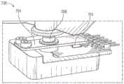
图7示出了被构造成收起机器人臂的示例性系统。FIG. 7 illustrates an example system configured to retract a robotic arm.
图8示出了被配置用于输尿管镜检查规程的基于台的机器人系统的实施方案。Figure 8 illustrates an embodiment of a table-based robotic system configured for a ureteroscopy procedure.
图9示出了被配置用于腹腔镜检查规程的基于台的机器人系统的实施方案。Figure 9 illustrates an embodiment of a table-based robotic system configured for a laparoscopy procedure.
图10示出了具有俯仰和倾斜调节的图5至图9的基于台的机器人系统的实施方案。FIG. 10 shows an embodiment of the table-based robotic system of FIGS. 5-9 with pitch and tilt adjustment.
图11提供了图5至图10的台和基于台的机器人系统的柱之间的接口的详细图示。11 provides a detailed illustration of the interface between the table of FIGS. 5-10 and the columns of the table-based robotic system.
图12示出了基于台的机器人系统的另选实施方案。Figure 12 shows an alternative embodiment of a table-based robotic system.
图13示出了图12的基于台的机器人系统的端视图。FIG. 13 shows an end view of the table-based robotic system of FIG. 12 .
图14示出了其上附接有机器人臂的基于台的机器人系统的端视图。Figure 14 shows an end view of a table-based robotic system with a robotic arm attached thereto.
图15示出了示例性器械驱动器。Figure 15 illustrates an exemplary instrument driver.
图16示出了具有成对器械驱动器的示例性医疗器械。Figure 16 shows an exemplary medical device with paired device drivers.
图17示出了器械驱动器和器械的另选设计,其中驱动单元的轴线平行于器械的细长轴的轴线。Figure 17 shows an alternative design of the instrument driver and instrument in which the axis of the drive unit is parallel to the axis of the elongate shaft of the instrument.
图18示出了具有基于器械的插入架构的器械。Figure 18 shows an instrument with an instrument-based insertion architecture.
图19示出了示例性控制器。Figure 19 shows an exemplary controller.
图20描绘了根据示例性实施方案的框图,该框图示出了估计图1至图10的机器人系统的一个或多个元件的位置(诸如图16至图18的器械的位置)的定位系统。20 depicts a block diagram illustrating a positioning system for estimating the position of one or more elements of the robotic system of FIGS. 1-10 , such as the position of the instruments of FIGS. 16-18 , according to an exemplary embodiment .
图21A和图21B示出了根据本公开的各方面的可形成机器人臂的一部分的示例性机器人连杆。21A and 21B illustrate example robotic linkages that may form part of a robotic arm according to aspects of the present disclosure.
图22示出了根据本公开的各方面的包括刚性外壳并且被构造成检测与外部对象的接触的示例性连杆。22 illustrates an example linkage that includes a rigid housing and is configured to detect contact with an external object, according to aspects of the present disclosure.
图23示出了根据本公开的各方面的可用于图22的连杆中的力感测连接件的一个示例。23 illustrates one example of a force sensing connection that may be used in the linkage of FIG. 22 in accordance with aspects of the present disclosure.
图24A示出了根据本公开的各方面的在连杆中包括十四个传感器的实施方案的两个视图。24A shows two views of an embodiment including fourteen sensors in a linkage according to aspects of the present disclosure.
图24B示出了根据本公开的各方面的在连杆中包括十二个传感器的实施方案的两个视图。24B shows two views of an embodiment including twelve sensors in a linkage according to aspects of the present disclosure.
图25是示出了根据本公开的各方面的可由外科机器人系统或其部件操作以用于检测机器人操纵器与外部对象之间的接触的示例性方法的流程图。25 is a flowchart illustrating an example method operable by a surgical robotic system or a component thereof for detecting contact between a robotic manipulator and an external object in accordance with aspects of the present disclosure.
图26示出了根据本公开的各方面的梁挠曲件传感器的实施方案。26 illustrates an embodiment of a beam flexure sensor according to aspects of the disclosure.
图27示出了根据本公开的各方面的梁挠曲件传感器的另一实施方案。27 illustrates another embodiment of a beam flexure sensor according to aspects of the present disclosure.
图28示出了根据本公开的各方面的可形成机器人臂的一部分的示例性机器人连杆。28 illustrates an example robotic linkage that may form part of a robotic arm in accordance with aspects of the present disclosure.
具体实施方式Detailed ways
1.概述。1. Overview .
本公开的各方面可集成到机器人使能的医疗系统中,该机器人使能的医疗系统能够执行多种医疗规程,包括微创规程诸如腹腔镜检查,以及非侵入规程诸如内窥镜检查两者。在内窥镜检查规程中,系统可能能够执行支气管镜检查、输尿管镜检查、胃镜检查等。Aspects of the present disclosure can be integrated into a robot-enabled medical system capable of performing a variety of medical procedures, including both minimally invasive procedures such as laparoscopy, and non-invasive procedures such as endoscopy . During an endoscopy procedure, the system may be able to perform bronchoscopy, ureteroscopy, gastroscopy, and the like.
除了执行广泛的规程之外,系统可以提供附加的益处,诸如增强的成像和指导以帮助医师。另外,该系统可以为医师提供从人体工程学方位执行规程的能力,而不需要笨拙的臂运动和方位。另外,该系统可以为医师提供以改进的易用性执行规程的能力,使得系统的器械中的一个或多个器械可由单个用户控制。In addition to performing extensive procedures, the system can provide additional benefits such as enhanced imaging and guidance to assist physicians. Additionally, the system may provide physicians with the ability to perform procedures from an ergonomic orientation without requiring awkward arm movements and orientations. Additionally, the system may provide physicians with the ability to perform procedures with improved ease of use such that one or more of the system's instruments may be controlled by a single user.
出于说明的目的,下文将结合附图描述各种实施方案。应当理解,所公开的概念的许多其他具体实施是可能的,并且利用所公开的具体实施可实现各种优点。标题包括在本文中以供参考并且有助于定位各个节段。这些标题并非旨在限制相对于其所述的概念的范围。此类概念可在整个说明书中具有适用性。For purposes of illustration, various embodiments are described below in conjunction with the accompanying figures. It should be understood that many other implementations of the disclosed concepts are possible and that various advantages can be realized using the disclosed implementations. Headings are included in this document for reference and to help locate individual sections. These headings are not intended to limit the scope of the concepts relative to them. Such concepts may have applicability throughout the specification.
A.机器人系统–推车。A. Robotic system – Cart .
机器人使能的医疗系统可以按多种方式配置,这取决于特定规程。图1示出了被布置用于诊断性和/或治疗性支气管镜检查的基于推车的机器人使能的系统10的实施方案。在支气管镜检查期间,系统10可包括推车11,该推车具有一个或多个机器人臂12,以将医疗器械诸如可操纵内窥镜13(其可以是用于支气管镜检查的规程特定的支气管镜)递送至自然孔口进入点(即,在本示例中定位在台上的患者的口),以递送诊断和/或治疗工具。如图所示,推车11可被定位在患者的上躯干附近,以便提供到进入点的通路。类似地,可致动机器人臂12以相对于进入点定位支气管镜。当利用胃镜(用于胃肠道(GI)规程的专用内窥镜)执行GI规程时,也可利用图1中的布置。图2更详细地描绘了推车的示例性实施方案。Robot-enabled medical systems can be configured in a variety of ways, depending on the particular protocol. Figure 1 shows an embodiment of a cart-based robot-enabled
继续参考图1,一旦推车11被正确定位,机器人臂12就可以机器人地、手动地或以其组合将可操纵内窥镜13插入患者体内。如图所示,可操纵内窥镜13可包括至少两个伸缩部分,诸如内引导件部分和外护套部分,每个部分联接到来自一组器械驱动器28的单独的器械驱动器,每个器械驱动器联接到单独的机器人臂的远侧端部。有利于将引导件部分与护套部分同轴对准的器械驱动器28的这种线性布置产生“虚拟轨道”29,该“虚拟轨道”可以通过将一个或多个机器人臂12操纵到不同角度和/或方位而在空间中被重新定位。本文所述的虚拟轨道在附图中使用虚线描绘,并且因此虚线未描绘系统的任何物理结构。器械驱动器28沿着虚拟轨道29的平移使内引导件部分相对于外护套部分伸缩,或者使内窥镜13从患者推进或回缩。虚拟轨道29的角度可基于临床应用或医师偏好来调节、平移和枢转。例如,在支气管镜检查中,如图所示的虚拟轨道29的角度和方位代表了在向医师提供到内窥镜13的通路同时使由内窥镜13弯曲到患者的口腔中引起的摩擦最小化之间的折衷。With continued reference to FIG. 1 , once the cart 11 is properly positioned, the
在插入之后,内窥镜13可以使用来自机器人系统的精确命令向下导向患者的气管和肺,直到到达目标目的地或手术部位。为了增强通过患者的肺网络的导航和/或达成期望的目标,内窥镜13可被操纵以从外护套部分伸缩地延伸内引导件部分,以获得增强的关节运动和更大的弯曲半径。使用单独的器械驱动器28还允许引导件部分和护套部分彼此独立地被驱动。After insertion, the
例如,内窥镜13可被引导以将活检针递送到目标,诸如例如患者肺内的病变或结节。针可沿工作通道向下部署,该工作通道延伸内窥镜的长度以获得待由病理学家分析的组织样本。根据病理结果,可沿内窥镜的工作通道向下部署附加工具以用于附加活检。在识别出结节是恶性的之后,内窥镜13可以通过内窥镜递送工具以切除潜在的癌组织。在一些情况下,诊断和治疗处理可在单独的规程中递送。在这些情况下,内窥镜13也可用于递送基准以“标记”目标结节的位置。在其他情况下,诊断和治疗处理可在相同的规程期间递送。For example,
系统10还可包括可移动塔30,该可移动塔可经由支撑缆线连接到推车11以向推车11提供对控制、电子、流体、光学、传感器和/或电力的支持。将这样的功能放置在塔30中允许可由操作医师和他/她的工作人员更容易地调节和/或重新定位的更小形状因子的推车11。另外,在推车/台与支撑塔30之间划分功能减少了手术室混乱并且有利于改善临床工作流程。虽然推车11可被定位成靠近患者,但是塔30可以在远程位置中被收起以在规程过程期间不挡道。
为了支持上述机器人系统,塔30可包括基于计算机的控制系统的部件,该基于计算机的控制系统将计算机程序指令存储在例如非暂态计算机可读存储介质(诸如永磁存储驱动器、固态驱动器等)内。无论执行是发生在塔30中还是发生在推车11中,这些指令的执行都可控制整个系统或其子系统。例如,当由计算机系统的处理器执行时,指令可致使机器人系统的部件致动相关托架和臂安装件,致动机器人臂,并且控制医疗器械。例如,响应于接收到控制信号,机器人臂的接头中的马达可将臂定位成特定姿势。To support the robotic systems described above,
塔30还可包括泵、流量计、阀控制器和/或流体通路,以便向可通过内窥镜13部署的系统提供受控的冲洗和抽吸能力。这些部件也可使用塔30的计算机系统来控制。在一些实施方案中,冲洗和抽吸能力可通过单独的缆线直接递送到内窥镜13。
塔30可包括电压和浪涌保护器,该电压和浪涌保护器被设计成向推车11提供经滤波和保护的电力,从而避免在推车11中放置电力变压器和其他辅助电力部件,从而得到更小,更可移动的推车11。
塔30还可包括用于在整个机器人系统10中部署的传感器的支撑设备。例如,塔30可包括用于在整个机器人系统10中检测、接收和处理从光学传感器或相机接收的数据的光电设备。结合控制系统,此类光电设备可用于生成实时图像,以用于在整个系统中部署的任何数量的控制台中显示(包括在塔30中显示)。类似地,塔30还可包括用于接收和处理从部署的电磁(EM)传感器接收到的信号的电子子系统。塔30还可用于容纳和定位EM场发生器,以便由医疗器械中或医疗器械上的EM传感器进行检测。
除了系统的其余部分中可用的其他控制台(例如,安装在推车顶部上的控制台)之外,塔30还可包括控制台31。控制台31可包括用于医师操作者的用户界面和显示屏,诸如触摸屏。系统10中的控制台通常设计成提供机器人控制以及规程的术前信息和实时信息两者,诸如内窥镜13的导航和定位信息。当控制台31不是医师可用的唯一控制台时,其可由第二操作者(诸如护士)使用以监测患者的健康状况或生命体征和系统10的操作,以及提供规程特定的数据,诸如导航和定位信息。在其他实施方案中,控制台31被容纳在与塔30分开的主体中。
塔30可通过一个或多个缆线或连接件(未示出)联接到推车11和内窥镜13。在一些实施方案中,可通过单根缆线向推车11提供来自塔30的支撑功能,从而简化手术室并消除手术室的混乱。在其他实施方案中,特定功能可联接在单独的布线和连接中。例如,虽然可以通过单个缆线向推车11提供电力,但也可以通过单独的缆线提供对控件、光学器件、流体和/或导航的支持。
图2提供了来自图1所示的基于推车的机器人使能的系统的推车11的实施方案的详细图示。推车11通常包括细长支撑结构14(通常称为“柱”)、推车基部15以及在柱14的顶部处的控制台16。柱14可包括一个或多个托架,诸如用于支持一个或多个机器人臂12(图2中示出三个)的部署的托架17(另选地为“臂支撑件”)。托架17可包括可单独配置的臂安装件,该臂安装件沿垂直轴线旋转以调节机器人臂12的基部,以相对于患者更好地定位。托架17还包括托架接口19,该托架接口允许托架17沿着柱14竖直地平移。FIG. 2 provides a detailed illustration of an embodiment of the cart 11 from the cart-based robot-enabled system shown in FIG. 1 . Cart 11 generally includes an elongated support structure 14 (commonly referred to as a “post”), a cart base 15 , and a
托架接口19通过狭槽(诸如狭槽20)连接到柱14,该狭槽被定位在柱14的相对侧上以引导托架17的竖直平移。狭槽20包括竖直平移接口以将托架17相对于推车基部15定位并且保持在各种竖直高度处。托架17的竖直平移允许推车11调节机器人臂12的到达范围以满足多种台高度、患者尺寸和医师偏好。类似地,托架17上的可单独配置的臂安装件允许机器人臂12的机器人臂基部21以多种配置成角度。
在一些实施方案中,狭槽20可补充有狭槽盖,该狭槽盖与狭槽表面齐平且平行,以防止灰尘和流体在托架17竖直平移时进入柱14的内部腔以及竖直平移接口。狭槽盖可通过被定位在狭槽20的竖直顶部和底部附近的成对弹簧卷轴部署。盖在卷轴内盘绕,直到在托架17竖直地上下平移时被部署成从盖的盘绕状态延伸和回缩。当托架17朝向卷轴平移时,卷轴的弹簧加载提供了将盖回缩到卷轴中的力,同时在托架17平移远离卷轴时也保持紧密密封。可使用例如托架接口19中的支架将盖连接到托架17,以有利于盖随着托架17平移而适当延伸和回缩。In some embodiments, the slot 20 may be supplemented with a slot cover that is flush and parallel to the slot surface to prevent dirt and fluids from entering the interior cavity of the column 14 and the vertical Straight translation interface. The slot cover is deployable by a pair of spring reels positioned near the vertical top and bottom of the slot 20 . The cap coils within the reel until deployed to extend and retract from the cap's coiled state as the
柱14可在内部包括机构,诸如齿轮和马达,该机构被设计成使用竖直对准的导螺杆以响应于响应用户输入(例如,来自控制台16的输入)生成的控制信号来以机械化方式平移托架17。Column 14 may internally include mechanisms, such as gears and motors, that are designed to mechanized using vertically aligned lead screws in response to control signals generated in response to user input (e.g., from console 16).
机器人臂12通常可包括由一系列连杆23分开的机器人臂基部21和端部执行器22,该一系列连杆由一系列接头24连接,每个接头包括独立的致动器,每个致动器包括可独立控制的马达。每个可独立控制的接头表示机器人臂12可用的独立自由度。机器人臂12中的每个机器人臂可具有七个接头,并且因此提供七个自由度。多个接头导致多个自由度,从而允许“冗余”的自由度。具有冗余自由度允许机器人臂12使用不同的连杆方位和接头角度将其相应的端部执行器22定位在空间中的特定方位、取向和轨迹处。这允许系统从空间中的期望点定位和导向医疗器械,同时允许医师使臂接头运动到远离患者的临床有利方位,以产生更大的接近,同时避免臂碰撞。The
推车基部15在地板上平衡柱14、托架17和机器人臂12的重量。因此,推车基部15容纳较重的部件,诸如电子器件、马达、电源以及使得推车11能够运动和/或固定的部件。例如,推车基部15包括允许推车11在规程之前容易地围绕房间运动的可滚动的轮形脚轮25。在到达适当方位之后,脚轮25可以使用轮锁固定,以在规程期间将推车11保持在适当方位。The cart base 15 balances the weight of the column 14,
定位在柱14的竖直端部处的控制台16允许用于接收用户输入的用户界面和显示屏(或两用装置,诸如例如触摸屏26)两者向医师用户提供术前和术中数据两者。触摸屏26上的潜在术前数据可以包括从术前计算机化断层摄影(CT)扫描导出的术前计划、导航和标测数据和/或来自术前患者面谈的记录。显示器上的术中数据可以包括从工具、传感器提供的光学信息和来自传感器的坐标信息以及重要的患者统计,诸如呼吸、心率和/或脉搏。控制台16可以被定位和倾斜成允许医师从柱14的与托架17相对的侧面进入控制台16。从该方位,医师可以在从推车11后面操作控制台16的同时观察控制台16、机器人臂12和患者。如图所示,控制台16还包括用以帮助操纵和稳定推车11的柄部27。The
图3示出了被布置用于输尿管镜检查的机器人使能的系统10的实施方案。在输尿管镜规程中,推车11可被定位成将输尿管镜32(被设计成横穿患者的尿道和输尿管的规程特定的内窥镜)递送到患者的下腹部区域。在输尿管镜检查中,可以期望输尿管镜32直接与患者的尿道对准以减少该区域中的敏感解剖结构上的摩擦和力。如图所示,推车11可在台的脚部处对准,以允许机器人臂12定位输尿管镜32,以用于直接线性进入患者的尿道。机器人臂12可从台的脚部沿着虚拟轨道33将输尿管镜32通过尿道直接插入患者的下腹部中。Figure 3 shows an embodiment of a robot-enabled
在插入尿道中之后,使用与支气管镜检查中类似的控制技术,输尿管镜32可被导航到膀胱、输尿管和/或肾中以用于诊断和/或治疗应用。例如,可以将输尿管镜32引导到输尿管和肾中以使用沿输尿管镜32的工作通道向下部署的激光或超声碎石装置来打碎积聚的肾结石。在碎石完成之后,可以使用沿输尿管镜32向下部署的篮移除所得的结石碎片。After insertion into the urethra, the
图4示出了类似地布置用于血管规程的机器人使能的系统10的实施方案。在血管规程中,系统10可被构造成使得推车11可将医疗器械34(诸如可操纵导管)递送到患者的腿部的股动脉中的进入点。股动脉呈现用于导航的较大直径以及到患者的心脏的相对较少的迂回且曲折的路径两者,这简化了导航。如在输尿管镜规程中,推车11可被定位成朝向患者的腿部和下腹部,以允许机器人臂12提供直接线性进入患者的大腿/髋部区域中的股动脉进入点的虚拟轨道35。在插入到动脉中之后,可通过平移器械驱动器28来导向和插入医疗器械34。另选地,推车可以被定位在患者的上腹部周围,以到达另选的血管进入点,诸如肩部和腕部附近的颈动脉和臂动脉。Figure 4 shows an embodiment of a robot-enabled
B.机器人系统–台。B. Robotic System – Desk .
机器人使能的医疗系统的实施方案还可结合患者的台。结合台通过移除推车减少了手术室内的资本设备的量,这允许更多地接近患者。图5示出了被布置用于支气管镜检查规程的这样的机器人使能的系统的实施方案。系统36包括用于将平台38(示出为“台”或“床”)支撑在地板上的支撑结构或柱37。与基于推车的系统非常相似,系统36的机器人臂39的端部执行器包括器械驱动器42,其被设计成通过或沿着由器械驱动器42的线性对准形成的虚拟轨道41来操纵细长医疗器械,诸如图5中的支气管镜40。在实践中,用于提供荧光镜成像的C形臂可通过将发射器和检测器放置在台38周围而定位在患者的上腹部区域上方。Embodiments of the robot-enabled medical system may also incorporate a patient's table. The combined table reduces the amount of capital equipment in the operating room by removing the cart, which allows greater access to the patient. Figure 5 shows an embodiment of such a robot-enabled system arranged for a bronchoscopy procedure. System 36 includes support structures or
图6提供了用于讨论目的的没有患者和医疗器械的系统36的另选视图。如图所示,柱37可包括在系统36中示出为环形的一个或多个托架43,该一个或多个机器人臂39可基于该托架。托架43可以沿着沿柱37的长度延伸的竖直柱接口44平移,以提供不同的有利点,机器人臂39可以从这些有利点被定位以到达患者。托架43可使用被定位在柱37内的机械马达围绕柱37旋转,以允许机器人臂39进入台38的多个侧面,诸如例如患者的两侧。在具有多个托架的实施方案中,托架可单独地被定位在柱上,并且可独立于其他托架平移和/或旋转。虽然托架43不需要环绕柱37或甚至是圆形的,但如图所示的环形形状有利于托架43围绕柱37旋转,同时保持结构平衡。托架43的旋转和平移允许系统36将医疗器械诸如内窥镜和腹腔镜对准到患者上的不同进入点中。在其他实施方案(未示出)中,系统36可包括具有可调式臂支撑件的病人检查台或病床,该可调式臂支撑件呈在病人检查台或病床旁边延伸的杆或轨道的形式。一个或多个机器人臂39(例如,经由具有肘接头的肩部)可附接到可调式臂支撑件,该可调式臂支撑件可被竖直调节。通过提供竖直调节,机器人臂39有利地能够紧凑地存放在病人检查台或病床下方,并且随后在规程期间升高。FIG. 6 provides an alternative view of the system 36 without the patient and medical instrument for discussion purposes. As shown,
机器人臂39可通过包括一系列接头的一组臂安装件45安装在托架43上,该接头可单独地旋转和/或伸缩地延伸以向机器人臂39提供附加的可配置性。另外,臂安装件45可被定位在托架43上,使得当托架43适当地旋转时,臂安装件45可被定位在台38的同一侧上(如图6所示)、台38的相对侧上(如图9所示)或台38的相邻侧上(未示出)。The robotic arm 39 may be mounted on a bracket 43 by a set of arm mounts 45 comprising a series of joints that are individually rotatable and/or telescopically extendable to provide additional configurability to the robotic arm 39 . Additionally, the arm mount 45 can be positioned on the bracket 43 so that when the bracket 43 is properly rotated, the arm mount 45 can be positioned on the same side of the table 38 (as shown in FIG. On the opposite side (as shown in FIG. 9 ) or on the adjacent side of the table 38 (not shown).
柱37在结构上为台38提供支撑,并且为托架43的竖直平移提供路径。在内部,柱37可配备有用于引导托架的竖直平移的导螺杆,以及用以机械化基于导螺杆的托架43的平移的马达。柱37还可将功率和控制信号传送到托架43和安装在其上的机器人臂39。
台基部46具有与图2所示的推车11中的推车基部15类似的功能,容纳较重的部件以平衡台/床38、柱37、托架43和机器人臂39。台基部46还可结合刚性脚轮以在规程期间提供稳定性。从台基部46的底部部署的脚轮可在基部46的两侧沿相反方向延伸,并且当系统36需要运动时回缩。The table base 46 has a similar function to the cart base 15 in the cart 11 shown in FIG. The table base 46 may also incorporate rigid casters to provide stability during a procedure. Casters deployed from the bottom of table base 46 may extend in opposite directions on either side of base 46 and retract when system 36 requires movement.
继续图6,系统36还可以包括塔(未示出),该塔使系统36的功能在台与塔之间进行划分以减小台的形状因子和体积。如在先前所公开的实施方案中,塔可以向台提供多种支持功能,诸如处理、计算和控制能力、电力、流体和/或光学以及传感器处理。塔还可以是可运动的,以远离患者定位,从而改善医师的接近并且消除手术室的混乱。另外,将部件放置在塔中允许在台基部46中有更多的存储空间,以用于机器人臂39的潜在收起。塔还可以包括主控制器或控制台,其提供用于用户输入的用户界面(诸如键盘和/或挂件)以及用于术前和术中信息(诸如实时成像、导航和跟踪信息)的显示屏(或触摸屏)两者。在一些实施方案中,塔还可包括用于待用于注气的气罐的夹持器。Continuing with FIG. 6 , the system 36 may also include towers (not shown) that allow the functions of the system 36 to be divided between stations to reduce the form factor and volume of the stations. As in previously disclosed embodiments, towers may provide various support functions to the station, such as processing, computing and control capabilities, electrical power, fluid and/or optical, and sensor processing. The tower may also be movable to be positioned away from the patient, improving physician access and eliminating operating room clutter. Additionally, placing the components in the tower allows more storage space in the table base 46 for potential stowing of the robotic arm 39 . The tower may also include a main controller or console that provides a user interface for user input, such as a keypad and/or pendant, and a display screen for preoperative and intraoperative information, such as real-time imaging, navigation, and tracking information (or touchscreen) both. In some embodiments, the tower may also include a holder for a gas tank to be used for gas injection.
在一些实施方案中,台基部可以在不使用时收起和存储机器人臂。图7示出了在基于台的系统的实施方案中收起机器人臂的系统47。在系统47中,托架48可以竖直平移到基部49中以使机器人臂50、臂安装件51和托架48收起在基部49内。基部盖52可以平移和回缩打开以围绕柱53部署托架48、臂安装件51和机器人臂50,并且闭合以收起该托架、臂安装件和机器人臂,以便在不使用时保护它们。基部盖52可利用膜54沿着其开口的边缘密封,以防止在闭合时灰尘和流体进入。In some embodiments, the table base can stow and store the robotic arm when not in use. Figure 7 shows a system 47 for retracting a robotic arm in an embodiment of a table-based system. In system 47 , bracket 48 can be translated vertically into base 49 to stow robotic arm 50 , arm mount 51 and bracket 48 within base 49 . The base cover 52 can translate and retract open to deploy the carriage 48, arm mount 51 and robot arm 50 about the column 53, and close to stow the carriage, arm mount and robot arm to protect them when not in use . The base cover 52 may be sealed along its open edge with a membrane 54 to prevent the ingress of dust and fluids when closed.
图8示出了被配置用于输尿管镜检查规程的机器人使能的基于台的系统的实施方案。在输尿管镜检查中,台38可以包括用于将患者定位成与柱37和台基部46成偏角的旋转部分55。旋转部分55可围绕枢转点(例如,位于患者的头部下方)旋转或枢转,以便将旋转部分55的底部部分定位成远离柱37。例如,旋转部分55的枢转允许C形臂(未示出)定位在患者的下腹部上方,而不与台38下方的柱(未示出)竞争空间。通过围绕柱37旋转托架(未示出),机器人臂39可沿着虚拟轨道57将输尿管镜56直接插入患者的腹股沟区域中以到达尿道。在输尿管镜检查中,镫58也可以固定至台38的旋转部分55,以在规程期间支撑患者的腿部的方位,并且允许完全通向患者的腹股沟区域。Figure 8 illustrates an embodiment of a robot-enabled table-based system configured for ureteroscopy procedures. During ureteroscopy, the table 38 may include a rotating portion 55 for positioning the patient at an off-angle to the
在腹腔镜检查规程中,通过患者的腹壁中的一个或多个小切口,可将微创器械插入患者的解剖结构中。在一些实施方案中,微创器械包括用于进入患者内的解剖结构的细长刚性构件,诸如轴。在患者腹腔充气之后,可以引导器械执行外科或医疗任务,诸如抓握、切割、消融、缝合等。在一些实施方案中,器械可以包括镜,诸如腹腔镜。图9示出了被配置用于腹腔镜检查规程的机器人使能的基于台的系统的实施方案。如图9所示,系统36的托架43可以被旋转并且竖直调节,以将成对的机器人臂39定位在台38的相对侧上,使得可以使用臂安装件45将器械59定位成穿过患者两侧上的最小切口以到达他/她的腹腔。During laparoscopy procedures, minimally invasive instruments may be inserted into the patient's anatomy through one or more small incisions in the patient's abdominal wall. In some embodiments, a minimally invasive device includes an elongated rigid member, such as a shaft, for accessing anatomy within a patient. After the patient's abdominal cavity is inflated, the instruments may be guided to perform surgical or medical tasks such as grasping, cutting, ablation, stapling, and the like. In some embodiments, the instrument may include a scope, such as a laparoscope. Figure 9 illustrates an embodiment of a robot-enabled table-based system configured for laparoscopy procedures. As shown in FIG. 9 , the carriage 43 of the system 36 can be rotated and adjusted vertically to position the pair of robotic arms 39 on opposite sides of the table 38 so that an instrument 59 can be positioned using the arm mounts 45 to pass through Minimal incisions are made on both sides of the patient to access his/her abdominal cavity.
为了适应腹腔镜检查规程,机器人使能的台系统还可将平台倾斜到期望的角度。图10示出了具有俯仰或倾斜调节的机器人使能的医疗系统的实施方案。如图10所示,系统36可以适应台38的倾斜,以将台的一部分定位在比另一部分距底板更远的距离处。另外,臂安装件45可以旋转以匹配倾斜,使得机器人臂39与台38保持相同的平面关系。为了适应更陡的角度,柱37还可以包括伸缩部分60,该伸缩部分允许柱37的竖直延伸以防止台38接触地板或与台基部46碰撞。To accommodate laparoscopy procedures, the robot-enabled table system can also tilt the platform to a desired angle. Figure 10 shows an embodiment of a robot-enabled medical system with pitch or tilt adjustment. As shown in FIG. 10, the system 36 can accommodate the tilt of the table 38 to position one portion of the table at a greater distance from the floor than another portion. Additionally, the arm mount 45 can be rotated to match the tilt so that the robotic arm 39 maintains the same planar relationship to the table 38 . To accommodate steeper angles, the
图11提供了台38与柱37之间的接口的详细图示。俯仰旋转机构61可被构造成以多个自由度改变台38相对于柱37的俯仰角。俯仰旋转机构61可以通过将正交轴线1、2定位在柱台接口处来实现,每条轴线由单独的马达3、4响应于电俯仰角命令而致动。沿着一个螺钉5的旋转将使得能够在一条轴线1中进行倾斜调节,而沿着另一个螺钉6的旋转将使得能够沿着另一个轴线2进行倾斜调节。在一些实施方案中,可使用球形接头来在多个自由度上改变台38相对于柱37的俯仰角。FIG. 11 provides a detailed illustration of the interface between
例如,当试图将台定位在头低脚高位(即,将患者的下腹部定位在比患者的上腹部距地板更高的方位)以用于下腹部手术时,俯仰调节特别有用。头低脚高位致使患者的内部器官通过重力滑向他/她的上腹部,从而清理出腹腔以使微创工具进入并且执行下腹部外科或医疗规程,诸如腹腔镜前列腺切除术。Pitch adjustment is particularly useful, for example, when attempting to position a table in a head-down position (ie, positioning the patient's lower abdomen at a higher orientation from the floor than the patient's upper abdomen) for lower abdominal surgery. The head-down position causes the patient's internal organs to slide by gravity towards his/her upper abdomen, clearing the abdominal cavity for minimally invasive tools to enter and perform lower abdominal surgical or medical procedures, such as laparoscopic prostatectomy.
图12和图13示出了基于台的外科机器人系统100的另选实施方案的等轴视图和端视图。外科机器人系统100包括可被构造成相对于台101支撑一个或多个机器人臂(参见例如图14)的一个或多个可调式臂支撑件105。在例示的实施方案中,示出了单个可调式臂支撑件105,但是附加的臂支撑件105可设置在台101的相对侧上。可调式臂支撑件105可被构造成使得其可相对于台101移动,以调节和/或改变可调式臂支撑件105和/或安装到该可调式臂支撑件的任何机器人臂相对于台101的方位。例如,可调式臂支撑件105可相对于台101被调节一个或多个自由度。可调式臂支撑件105为系统100提供高灵活性,包括容易地将该一个或多个可调式臂支撑件105和附接到其的任何机器人臂收起在台101下方的能力。可调式臂支撑件105可从收起方位升高到台101的上表面下方的方位。在其他实施方案中,可调式臂支撑件105可从收起方位升高到台101的上表面上方的方位。12 and 13 show isometric and end views of an alternative embodiment of a table-based surgical
可调式臂支撑件105可提供若干自由度,包括提升、侧向平移、倾斜等。在图12和图13的例示实施方案中,臂支撑件105被构造成具有四个自由度,这些自由度在图12中用箭头示出。第一自由度允许在z方向上(“Z提升”)调节可调式臂支撑件105。例如,可调式臂支撑件105可包括托架109,该托架被构造成沿着或相对于支撑台101的柱102向上或向下移动。第二自由度可允许可调式臂支撑件105倾斜。例如,可调式臂支撑件105可包括旋转接头,该旋转接头可允许可调式臂支撑件105在头低脚高位与床对准。第三自由度可允许可调式臂支撑件105“向上枢转”,这可用于调节台101的一侧与可调式臂支撑件105之间的距离。第四自由度可允许可调式臂支撑件105沿着台的纵向长度平移。The
图12和图13中的外科机器人系统100可包括由安装到基部103的柱102支撑的台。基部103和柱102相对于支撑表面支撑台101。地板轴线131和支撑轴线133在图13中示出。Surgical
可调式臂支撑件105可安装到柱102。在其他实施方案中,臂支撑件105可安装到台101或基部103。可调式臂支撑件105可包括托架109、杆或轨道连接器111以及杆或轨道107。在一些实施方案中,安装到轨道107的一个或多个机器人臂可相对于彼此平移和移动。An
托架109可通过第一接头113附接到柱102,该第一接头允许托架109相对于柱102移动(例如,诸如沿第一轴线或竖直轴线123上下移动)。第一接头113可向可调式臂支撑件105提供第一自由度(“Z提升”)。可调式臂支撑件105可包括第二接头115,该第二接头为可调式臂支撑件105提供第二自由度(倾斜)。可调式臂支撑件105可包括第三接头117,该第三接头可为可调式臂支撑件105提供第三自由度(“向上枢转”)。可提供附加接头119(在图13中示出),该附加接头机械地约束第三接头117以在轨道连接器111围绕第三轴线127旋转时保持轨道107的取向。可调式臂支撑件105可包括第四接头121,该第四接头可沿着第四轴线129为可调式臂支撑件105提供第四自由度(平移)。The
图14示出了根据一个实施方案的具有安装在台101的相对侧上的两个可调式臂支撑件105A、105B的外科机器人系统140A的端视图。第一机器人臂142A附接到第一可调式臂支撑件105B的杆或轨道107A。第一机器人臂142A包括附接到轨道107A的基部144A。第一机器人臂142A的远侧端部包括可附接到一个或多个机器人医疗器械或工具的器械驱动机构146A。类似地,第二机器人臂142B包括附接到轨道107B的基部144B。第二机器人臂142B的远侧端部包括器械驱动机构146B。器械驱动机构146B可被构造成附接到一个或多个机器人医疗器械或工具。Figure 14 shows an end view of a surgical
在一些实施方案中,机器人臂142A、142B中的一者或多者包括具有七个或更多个自由度的臂。在一些实施方案中,机器人臂142A、142B中的一者或多者可包括八个自由度,包括插入轴线(包括插入的1个自由度)、腕部(包括腕部俯仰、偏航和滚动的3个自由度)、肘部(包括肘部俯仰的1个自由度)、肩部(包括肩部俯仰和偏航的2个自由度)以及基部144A、144B(包括平移的1个自由度)。在一些实施方案中,插入自由度可由机器人臂142A、142B提供,而在其他实施方案中,器械本身经由基于器械的插入架构提供插入。In some embodiments, one or more of the
C.器械驱动器和接口。C. Device drivers and interfaces .
系统的机器人臂的端部执行器可包括:(i)器械驱动器(另选地称为“器械驱动机构”或“器械装置操纵器”),该器械驱动器结合了用于致动医疗器械的机电装置;以及(ii)可移除或可拆卸的医疗器械,该医疗器械可以没有任何机电部件,诸如马达。该二分法可能是由以下所驱动的:对医疗规程中使用的医疗器械进行灭菌的需要;以及由于昂贵的资本设备的复杂机械组件和敏感电子器件而不能对昂贵的资本设备进行充分灭菌。因此,医疗器械可以被设计成从器械驱动器(以及因此从系统)拆卸、移除和互换,以便由医师或医师的工作人员单独灭菌或处置。相比之下,器械驱动器不需要被改变或灭菌,并且可以被覆盖以便保护。The end effector of the robotic arm of the system may include: (i) an instrument driver (alternatively referred to as an "instrument drive mechanism" or "instrument device manipulator") that incorporates electromechanical mechanisms for actuating a medical instrument devices; and (ii) removable or detachable medical devices, which may be free of any electromechanical components, such as motors. This dichotomy may be driven by: the need to sterilize medical devices used in medical procedures; and the inability to adequately sterilize expensive capital equipment due to its complex mechanical components and sensitive electronics . Accordingly, the medical device may be designed to be detached, removed and interchanged from the device driver (and thus the system) for individual sterilization or disposal by a physician or physician's staff. In contrast, instrument drivers do not need to be altered or sterilized, and can be covered for protection.
图15示出了示例性器械驱动器。定位在机器人臂的远侧端部处的器械驱动器62包括一个或多个驱动单元63,该一个或多个驱动单元以平行轴线布置以经由驱动轴64向医疗器械提供受控扭矩。每个驱动单元63包括用于与器械相互作用的单独的驱动轴64,用于将马达轴旋转转换成期望扭矩的齿轮头65,用于生成驱动扭矩的马达66,用以测量马达轴的速度并且向控制电路提供反馈的编码器67,以及用于接收控制信号并且致动驱动单元的控制电路68。每个驱动单元63被独立地控制和机动化,器械驱动器62可向医疗器械提供多个(例如,如图15所示为四个)独立的驱动输出部。在操作中,控制电路68将接收控制信号,将马达信号传输至马达66,将由编码器67测量的所得马达速度与期望速度进行比较,并且调制马达信号以生成期望扭矩。Figure 15 illustrates an exemplary instrument driver. An instrument driver 62 positioned at the distal end of the robotic arm includes one or more drive units 63 arranged in parallel axes to provide controlled torque to the medical instrument via a drive shaft 64 . Each drive unit 63 includes a separate drive shaft 64 for interacting with the instrument, a
对于需要无菌环境的规程,机器人系统可以结合驱动接口,诸如连接至无菌覆盖件的无菌适配器,其位于器械驱动器与医疗器械之间。无菌适配器的主要目的是将角运动从器械驱动器的驱动轴传递到器械的驱动输入部,同时保持驱动轴与驱动输入部之间的物理分离并且因此保持无菌。因此,示例性无菌适配器可以包括旨在与器械驱动器的驱动轴和器械上的驱动输入部配合的一系列旋转输入部和旋转输出部。连接到无菌适配器的由薄的柔性材料(诸如透明或半透明塑料)组成的无菌覆盖件被设计成覆盖资本设备,诸如器械驱动器、机器人臂和推车(在基于推车的系统中)或台(在基于台的系统中)。覆盖件的使用将允许资本设备被定位在患者附近,同时仍然位于不需要灭菌的区域(即,非无菌区)。在无菌覆盖件的另一侧上,医疗器械可以在需要灭菌的区域(即,无菌区)与患者对接。For procedures requiring a sterile environment, the robotic system may incorporate an actuation interface, such as a sterile adapter connected to a sterile cover, between the instrument actuator and the medical instrument. The primary purpose of a sterile adapter is to transfer angular motion from the drive shaft of the instrument driver to the drive input of the instrument while maintaining physical separation between the drive shaft and drive input and thus maintaining sterility. Thus, an exemplary sterile adapter may include a series of rotational inputs and rotational outputs intended to mate with the drive shaft of the instrument driver and the drive input on the instrument. A sterile cover composed of a thin, flexible material, such as clear or translucent plastic, attached to a sterile adapter designed to cover capital equipment such as instrument drives, robotic arms, and carts (in cart-based systems) or a station (in a station-based system). The use of covers would allow capital equipment to be positioned near the patient while still being located in areas that do not require sterilization (ie, non-sterile areas). On the other side of the sterile cover, the medical device can interface with the patient in the area to be sterilized (ie, the sterile field).
D.医疗器械。D.Medical devices .
图16示出了具有成对器械驱动器的示例性医疗器械。与被设计成与机器人系统一起使用的其他器械类似,医疗器械70包括细长轴71(或细长主体)和器械基部72。由于其用于由医师进行的手动交互的预期设计而也被称为“器械柄部”的器械基部72通常可包括可旋转驱动输入部73(例如,插孔、滑轮或卷轴),该驱动输入部被设计成与延伸通过机器人臂76的远侧端部处的器械驱动器75上的驱动接口的驱动输出部74配合。当物理连接、闩锁和/或联接时,器械基部72的配合的驱动输入部73可与器械驱动器75中的驱动输出部74共享旋转轴线,以允许扭矩从驱动输出部74传递到驱动输入部73。在一些实施方案中,驱动输出部74可包括花键,该花键被设计成与驱动输入部73上的插孔配合。Figure 16 shows an exemplary medical device with paired device drivers. Like other instruments designed for use with robotic systems, medical instrument 70 includes an elongated shaft 71 (or elongated body) and an instrument base 72 . Instrument base 72, also referred to as an "instrument handle" due to its intended design for manual interaction by a physician, may generally include a rotatable drive input 73 (e.g., a socket, pulley, or reel) that The portion is designed to mate with a drive output portion 74 extending through a drive interface on an instrument driver 75 at the distal end of the
细长轴71被设计成通过解剖开口或内腔(例如,如在内窥镜检查中)或通过微创切口(例如,如在腹腔镜检查中)递送。细长轴71可以是柔性的(例如,具有类似于内窥镜的特性)或刚性的(例如,具有类似于腹腔镜的特性),或包括柔性部分和刚性部分两者的定制组合。当被设计用于腹腔镜检查时,刚性细长轴的远侧端部可以连接到端部执行器,该端部执行器从由具有至少一个自由度的连接叉形成的接头腕和外科工具或医疗器械(诸如例如,抓握器或剪刀)延伸,当驱动输入部响应于从器械驱动器75的驱动输出部74接收到的扭矩而旋转时,该外科工具可以基于来自腱的力来致动。当设计用于内窥镜检查时,柔性细长轴的远侧端部可包括可操纵或可控制的弯曲节段,该弯曲节段以基于从器械驱动器75的驱动输出部74接收到的扭矩而进行关节运动和弯曲。The elongated shaft 71 is designed to be delivered through an anatomical opening or lumen (eg, as in endoscopy) or through a minimally invasive incision (eg, as in laparoscopy). The elongated shaft 71 may be flexible (eg, have endoscope-like properties) or rigid (eg, have laparoscope-like properties), or include a custom combination of both flexible and rigid portions. When designed for laparoscopy, the distal end of the rigid elongated shaft may be connected to an end effector derived from a joint wrist formed by a connecting fork with at least one degree of freedom and a surgical tool or Extending the medical instrument, such as, for example, a grasper or scissors, the surgical tool can be actuated based on force from the tendon as the drive input rotates in response to torque received from the drive output 74 of the instrument driver 75 . When designed for endoscopy, the distal end of the flexible elongated shaft may include a steerable or controllable curved section that bends in a manner based on the torque received from the drive output 74 of the instrument driver 75. for joint movement and flexion.
使用沿着细长轴71的腱沿着细长轴71传递来自器械驱动器75的扭矩。这些单独的腱(诸如牵拉线)可单独地锚定至器械柄部72内的单独的驱动输入部73。从器械柄部72,沿着细长轴71的一个或多个牵拉腔向下引导腱并且将其锚定在细长轴71的远侧部分处,或者锚定在细长轴的远侧部分处的腕部中。在外科规程诸如腹腔镜、内窥镜或混合规程期间,这些腱可以联接到远侧安装的端部执行器,诸如腕部、抓握器或剪刀。在这样的布置下,施加在驱动输入部73上的扭矩将张力传递到腱,从而引起端部执行器以某种方式致动。在一些实施方案中,在外科规程期间,腱可以致使接头围绕轴线旋转,从而致使端部执行器沿一个方向或另一个方向运动。另选地,腱可以连接到细长轴71的远侧端部处的抓握器的一个或多个钳口,其中来自腱的张力致使抓握器闭合。Torque from instrument driver 75 is transmitted along elongated shaft 71 using a tendon along elongated shaft 71 . These individual tendons, such as puller wires, may be individually anchored to individual drive inputs 73 within the instrument handle 72 . From the instrument handle 72, one or more pull lumens along the elongated shaft 71 guide the tendon down and anchor it at the distal portion of the elongated shaft 71, or at the distal end of the elongated shaft part of the wrist. During surgical procedures such as laparoscopic, endoscopic or hybrid procedures, these tendons may be coupled to distally mounted end effectors such as wrists, graspers or scissors. In such an arrangement, torque applied to drive input 73 transmits tension to the tendon, causing the end effector to actuate in a certain manner. In some embodiments, during a surgical procedure, the tendon can cause the joint to rotate about the axis, thereby causing the end effector to move in one direction or the other. Alternatively, the tendons may be connected to one or more jaws of the grasper at the distal end of the elongate shaft 71, where tension from the tendons causes the graspers to close.
在内窥镜检查中,腱可经由粘合剂、控制环或其他机械固定件联接到沿着细长轴71定位(例如,在远侧端部处)的弯曲或关节运动节段。当固定地附接到弯曲节段的远侧端部时,施加在驱动输入部73上的扭矩将沿腱向下传递,从而引起较软的弯曲节段(有时称为可关节运动节段或区域)弯曲或进行关节运动。沿着不弯曲节段,可以有利的是,使单独的牵拉腔螺旋或盘旋,该牵拉腔沿着内窥镜轴的壁(或在内部)导向单独的腱,以平衡由牵拉线中的张力引起的径向力。为了特定目的,可以改变或设计螺旋的角度和/或它们之间的间隔,其中更紧的螺旋在负载力下表现出较小的轴压缩,而较低的螺旋量在负载力下引起更大的轴压缩,但限制弯曲。在另一种情况下,可平行于细长轴71的纵向轴线来导向牵拉腔以允许在期望的弯曲或可关节运动节段中进行受控关节运动。In endoscopy, the tendon may be coupled to a flexure or articulation segment positioned along the elongate shaft 71 (eg, at the distal end) via an adhesive, control ring, or other mechanical fixation. When fixedly attached to the distal end of the flexure segment, torque applied to the drive input 73 will be transmitted down the tendon, causing a softer flexure segment (sometimes referred to as the articulable segment or area) to bend or articulate. Along the unbent segment, it may be advantageous to helicate or spiral a separate puller lumen that leads along the wall (or inside) of the endoscope shaft to a separate tendon to balance the puller wire The radial force caused by the tension in . The angle of the helices and/or the spacing between them can be varied or designed for specific purposes, with tighter helixes exhibiting less shaft compression under load forces, while lower helix amounts induce greater The shaft compresses but limits bending. In another instance, the pull lumen may be directed parallel to the longitudinal axis of the elongated shaft 71 to allow controlled articulation in the desired flexure or articulation segment.
在内窥镜检查中,细长轴71容纳多个部件以辅助机器人规程。轴71可以在轴71的远侧端部处包括用于部署外科工具(或医疗器械)、对手术区域进行冲洗和/或抽吸的工作通道。轴71还可以适应线和/或光纤以向远侧末端处的光学组件/从远侧末端处的光学组件传递信号,该光学组件可以包括光学相机。轴71也可以适应光纤,以将来自位于近侧的光源(诸如,发光二极管)的光载送到轴71的远侧端部。In endoscopy, the elongated shaft 71 houses a number of components to aid in robotic procedures. The shaft 71 may include a working channel at the distal end of the shaft 71 for deploying surgical tools (or medical instruments), irrigation and/or suction of the surgical field. The shaft 71 may also accommodate wires and/or optical fibers to deliver signals to/from an optical assembly at the distal tip, which may include an optical camera. The shaft 71 may also accommodate an optical fiber to carry light from a proximally located light source, such as a light emitting diode, to the distal end of the shaft 71 .
在器械70的远侧端部处,远侧末端还可包括用于将用于诊断和/或治疗、冲洗和抽吸的工具递送到手术部位的工作通道的开口。远侧末端还可以包括用于相机(诸如纤维镜或数码相机)的端口,以捕获内部解剖空间的图像。相关地,远侧末端还可以包括用于光源的端口,该光源用于在使用相机时照亮解剖空间。At the distal end of instrument 70, the distal tip may also include an opening to the working channel for delivering tools for diagnosis and/or treatment, irrigation and aspiration to the surgical site. The distal tip may also include a port for a camera, such as a fiberscope or digital camera, to capture images of the internal anatomical space. Relatedly, the distal tip may also include a port for a light source for illuminating the anatomical space when using the camera.
在图16的示例中,驱动轴轴线以及因此驱动输入部轴线与细长轴71的轴线正交。然而,该布置使细长轴71的滚转能力复杂化。沿着细长轴71的轴线滚转该细长轴同时保持驱动输入部73静止会引起当腱从驱动输入部73延伸出去并且进入细长轴71内的牵拉腔时,腱的不期望的缠结。所得到的这样的腱的缠结可能破坏旨在在内窥镜规程期间预测柔性细长轴71的运动的任何控制算法。In the example of FIG. 16 , the drive shaft axis, and thus the drive input axis, is orthogonal to the axis of the elongated shaft 71 . However, this arrangement complicates the rollability of the elongated shaft 71 . Rolling the elongated shaft 71 along its axis while holding the drive input 73 stationary can cause undesired movement of the tendon as it extends from the drive input 73 and into the traction lumen within the elongated shaft 71. tangle. The resulting entanglement of such tendons could disrupt any control algorithm intended to predict the movement of the flexible elongated shaft 71 during an endoscopic procedure.
图17示出了器械驱动器和器械的另选设计,其中驱动单元的轴线平行于器械的细长轴的轴线。如图所示,圆形器械驱动器80包括四个驱动单元,其驱动输出部81在机器人臂82的端部处平行对准。驱动单元和它们各自的驱动输出部81容纳在由组件83内的驱动单元中的一个驱动单元驱动的器械驱动器80的旋转组件83中。响应于由旋转驱动单元提供的扭矩,旋转组件83沿着圆形轴承旋转,该圆形轴承将旋转组件83连接到器械驱动器80的非旋转部分84。可以通过电接触将电力和控制信号从器械驱动器80的非旋转部分84传送至旋转组件83,该电接触可以通过电刷滑环连接(未示出)的旋转来保持。在其他实施方案中,旋转组件83可以响应于集成到不可旋转部分84中的单独的驱动单元,并且因此不平行于其他驱动单元。旋转机构83允许器械驱动器80允许驱动单元及其相应的驱动输出部81作为单个单元围绕器械驱动器轴线85旋转。Figure 17 shows an alternative design of the instrument driver and instrument in which the axis of the drive unit is parallel to the axis of the elongate shaft of the instrument. As shown, the circular instrument driver 80 includes four drive units whose drive outputs 81 are aligned in parallel at the end of the
与先前所公开的实施方案类似,器械86可包括细长轴部分88和器械基部87(出于讨论的目的,示出为具有透明的外部表层),该器械基部包括被构造成接收器械驱动器80中的驱动输出部81的多个驱动输入部89(诸如插孔、滑轮和卷轴)。与先前公开的实施方案不同,器械轴88从器械基部87的中心延伸,该器械基部的轴线基本上平行于驱动输入部89的轴线,而不是如图16的设计中那样正交。Similar to the previously disclosed embodiments, the instrument 86 may include an elongated shaft portion 88 and an instrument base 87 (shown with a transparent outer skin for purposes of discussion) that includes an instrument driver 80 configured to receive the instrument driver 80. A plurality of drive inputs 89 (such as sockets, pulleys and reels) of the drive output 81 in the drive. Unlike previously disclosed embodiments, instrument shaft 88 extends from the center of instrument base 87 whose axis is substantially parallel to the axis of drive input 89 rather than orthogonal as in the design of FIG. 16 .
当联接到器械驱动器80的旋转组件83时,包括器械基部87和器械轴88的医疗器械86与旋转组件83组合地围绕器械驱动器轴线85旋转。由于器械轴88被定位在器械基部87的中心处,因此当附接时器械轴88与器械驱动器轴线85同轴。因此,旋转组件83的旋转致使器械轴88围绕其自身的纵向轴线旋转。此外,当器械基部87与器械轴88一起旋转时,连接到器械基部87中的驱动输入部89的任何腱在旋转期间都不缠结。因此,驱动输出部81、驱动输入部89和器械轴88的轴线的平行允许轴在不会使任何控制腱缠结的情况下旋转。When coupled to the rotation assembly 83 of the instrument driver 80 , the medical instrument 86 including the instrument base 87 and the instrument shaft 88 rotates in combination with the rotation assembly 83 about the instrument driver axis 85 . Since the instrument shaft 88 is positioned at the center of the instrument base 87, the instrument shaft 88 is coaxial with the instrument driver axis 85 when attached. Thus, rotation of the rotation assembly 83 causes the instrument shaft 88 to rotate about its own longitudinal axis. Furthermore, as the instrument base 87 rotates with the instrument shaft 88, any tendons connected to the drive input 89 in the instrument base 87 do not become tangled during rotation. Thus, the parallelism of the axes of drive output 81 , drive input 89 and instrument shaft 88 allows the shaft to rotate without tangling any of the control tendons.
图18示出了根据一些实施方案的具有基于器械的插入架构的器械。器械150可联接到上文所述的器械驱动器中的任一个器械驱动器。器械150包括细长轴152、连接到轴152的端部执行器162和联接到轴152的柄部170。细长轴152包括管状构件,该管状构件具有近侧部分154和远侧部分156。细长轴152沿着其外表面包括一个或多个通道或凹槽158。凹槽158被构造成接纳通过该凹槽的一根或多根线材或缆线180。因此,一根或多根缆线180沿着细长轴152的外表面延伸。在其他实施方案中,缆线180也可穿过细长轴152。所述一根或多根缆线180的操纵(例如,经由器械驱动器)使得端部执行器162的致动。Figure 18 illustrates an instrument with an instrument-based insertion architecture, according to some embodiments. The
器械柄部170(也可称为器械基部)通常可包括附接接口172,该附接接口具有一个或多个机械输入件174,例如插孔、滑轮或卷轴,所述一个或多个机械输入件被设计成与器械驱动器的附接表面上的一个或多个扭矩联接器往复地配合。The instrument handle 170 (which may also be referred to as an instrument base) may generally include an
在一些实施方案中,器械150包括使得细长轴152能够相对于柄部170平移的一系列滑轮或缆线。换句话讲,器械150本身包括基于器械的插入架构,该基于器械的插入架构适应器械的插入,从而使对机器人臂的依赖最小化以提供器械150的插入。在其他实施方案中,机器人臂可以很大程度上负责器械插入。In some embodiments,
E.控制器。E. Controller .
本文所述的机器人系统中的任一个机器人系统可包括用于操纵附接到机器人臂的器械的输入装置或控制器。在一些实施方案中,控制器可与器械(例如,通信地、电子地、电气、无线地和/或机械地)耦合,使得控制器的操纵例如经由主从控制而致使器械对应操纵。Any of the robotic systems described herein may include an input device or controller for manipulating an implement attached to the robotic arm. In some embodiments, a controller may be coupled (eg, communicatively, electronically, electrically, wirelessly, and/or mechanically) to an instrument such that manipulation of the controller results in corresponding manipulation of the instrument, eg, via master-slave control.
图19是控制器182的实施方案的透视图。在本实施方案中,控制器182包括可具有阻抗和导纳控制两者的混合控制器。在其他实施方案中,控制器182可仅利用阻抗或被动控制。在其他实施方案中,控制器182可仅利用导纳控制。通过作为混合控制器,控制器182有利地在使用时可具有较低的感知惯性。FIG. 19 is a perspective view of an embodiment of a
在例示的实施方案中,控制器182被构造成允许操纵两个医疗器械,并且包括两个柄部184。柄部184中的每个柄部连接到万向支架186。每个万向支架186连接到定位平台188。In the illustrated embodiment, the
如图19所示,每个定位平台188包括通过棱柱接头196联接到柱194的选择顺应性装配机器人臂(SCARA)198。棱柱接头196被构造成沿着柱194(例如,沿着轨道197)平移,以允许柄部184中的每个柄部在z方向上平移,从而提供第一自由度。SCARA 198被构造成允许柄部184在x-y平面中运动,从而提供两个附加自由度。As shown in FIG. 19 , each
在一些实施方案中,一个或多个负荷传感器被定位在控制器中。例如,在一些实施方案中,负荷传感器(未示出)被定位在万向支架186中的每个万向支架的主体中。通过提供负荷传感器,控制器182的部分能够在导纳控制下操作,从而在使用时有利地减小控制器的感知惯性。在一些实施方案中,定位平台188被配置用于导纳控制,而万向支架186被配置用于阻抗控制。在其他实施方案中,万向支架186被配置用于导纳控制,而定位平台188被配置用于阻抗控制。因此,对于一些实施方案,定位平台188的平移自由度或方位自由度可依赖于导纳控制,而万向支架186的旋转自由度依赖于阻抗控制。In some embodiments, one or more load sensors are located in the controller. For example, in some embodiments, load sensors (not shown) are positioned in the body of each of the
F.导航和控制。F. Navigation and Control .
传统的内窥镜检查可以涉及使用荧光透视(例如,如可以通过C形臂递送的)和其他形式的基于辐射的成像模态,以向操作医师提供腔内指导。相比之下,本公开所设想的机器人系统可以提供基于非辐射的导航和定位装置,以减少医师暴露于辐射并且减少手术室内的设备的量。如本文所用,术语“定位”可以指确定和/或监测对象在参考坐标系中的方位。诸如术前标测、计算机视觉、实时EM跟踪和机器人命令数据的技术可以单独地或组合地使用以实现无辐射操作环境。在仍使用基于辐射的成像模态的其他情况下,可以单独地或组合地使用术前标测、计算机视觉、实时EM跟踪和机器人命令数据,以改进仅通过基于辐射的成像模态获得的信息。Traditional endoscopy may involve the use of fluoroscopy (eg, as may be delivered by a C-arm) and other forms of radiation-based imaging modalities to provide intraluminal guidance to the operating physician. In contrast, robotic systems contemplated by the present disclosure can provide non-radiation based navigation and positioning means to reduce physician exposure to radiation and reduce the amount of equipment in an operating room. As used herein, the term "positioning" may refer to determining and/or monitoring the orientation of an object in a reference coordinate system. Technologies such as preoperative mapping, computer vision, real-time EM tracking, and robotic command data can be used individually or in combination to achieve a radiation-free operating environment. In other cases where radiation-based imaging modalities are still used, preoperative mapping, computer vision, real-time EM tracking, and robotic command data can be used alone or in combination to refine the information obtained with radiation-based imaging modalities alone .
图20是示出了根据示例性实施方案的估计机器人系统的一个或多个元件的位置(诸如器械的位置)的定位系统90的框图。定位系统90可以是被配置成执行一个或多个指令的一个或多个计算机装置的集合。计算机装置可以由上文讨论的一个或多个部件中的处理器(或多个处理器)和计算机可读存储器来体现。通过示例而非限制,计算机装置可以位于图1所示的塔30、图1至图4所示的推车11、图5至图14所示的床等中。20 is a block diagram illustrating a localization system 90 for estimating the position of one or more elements of a robotic system, such as the position of an instrument, according to an exemplary embodiment. Positioning system 90 may be a collection of one or more computer devices configured to execute one or more instructions. The computer means may be embodied by a processor (or multiple processors) and a computer readable memory in one or more of the components discussed above. By way of example and not limitation, the computer device may be located in the
如图20所示,定位系统90可包括定位模块95,该定位模块处理输入数据91-94以生成用于医疗器械的远侧末端的位置数据96。位置数据96可以是表示器械的远侧端部相对于参考系的位置和/或取向的数据或逻辑。参考系可以是相对于患者解剖结构或已知对象(诸如EM场发生器)的参考系(参见下文对于EM场发生器的讨论)。As shown in FIG. 20, positioning system 90 may include a positioning module 95 that processes input data 91-94 to generate
现在更详细地描述各种输入数据91-94。定位模块95可使用术前标测来生成模型数据91。术前标测可以通过使用低剂量CT扫描的集合来完成。术前CT扫描被重建为三维图像,该三维图像被可视化,例如作为患者的内部解剖结构的剖面图的“切片”。当总体上分析时,可以生成用于患者的解剖结构(诸如患者肺网络)的解剖腔、空间和结构的基于图像的模型。可以从CT图像确定和近似诸如中心线几何形状的技术,以形成患者解剖结构的三维体积,其被称为模型数据91(当仅使用术前CT扫描生成时也称为“术前模型数据”)。中心线几何形状的使用在美国专利申请14/523,760中有所讨论,其内容全文并入本文中。网络拓扑模型也可以从CT图像中导出,并且特别适合于支气管镜检查。The various input data 91-94 are now described in more detail. Localization module 95 may use pre-operative mapping to generate model data 91 . Preoperative mapping can be accomplished using a collection of low-dose CT scans. The preoperative CT scan is reconstructed into a three-dimensional image that is visualized, for example, as a "slice" of a cross-sectional view of the patient's internal anatomy. When analyzed as a whole, an image-based model of the anatomical cavities, spaces, and structures for the patient's anatomy, such as the patient's lung network, can be generated. Techniques such as centerline geometry can be determined and approximated from CT images to form a three-dimensional volume of the patient's anatomy, referred to as model data 91 (also referred to as "preoperative model data" when generated using only preoperative CT scans ). The use of centerline geometry is discussed in US patent application Ser. No. 14/523,760, the contents of which are incorporated herein in their entirety. Network topology models can also be derived from CT images and are particularly suitable for bronchoscopy.
在一些实施方案中,器械可以配备有相机以向定位模块95提供视觉数据(或图像数据)92。定位模块95可处理视觉数据92以实现一个或多个基于视觉的(或基于图像的)位置跟踪模块或特征部。例如,术前模型数据91可以与视觉数据92结合使用,以实现对医疗器械(例如,内窥镜或推进通过内窥镜的工作通道的器械)的基于计算机视觉的跟踪。例如,使用术前模型数据91,机器人系统可以基于内窥镜的行进预期路径根据模型生成预期内窥镜图像的库,每个图像连接到模型内的位置。在外科手术进行时,机器人系统可以参考该库,以便将在相机(例如,在内窥镜的远侧端部处的相机)处捕获的实时图像与图像库中的那些图像进行比较,以辅助定位。In some embodiments, the instrument may be equipped with a camera to provide visual data (or image data) 92 to localization module 95 . Positioning module 95 may process vision data 92 to implement one or more vision-based (or image-based) position tracking modules or features. For example, pre-operative model data 91 may be used in conjunction with vision data 92 to enable computer vision-based tracking of a medical instrument (eg, an endoscope or an instrument advanced through a working channel of an endoscope). For example, using the pre-operative model data 91, the robotic system can generate from the model a library of expected endoscopic images, each image linked to a location within the model, based on the expected path of travel of the endoscope. As the surgical procedure progresses, the robotic system can refer to this library to compare real-time images captured at a camera (e.g., at the distal end of an endoscope) with those in the image library to assist in position.
其他基于计算机视觉的跟踪技术使用特征跟踪来确定相机的运动,并且因此确定内窥镜的运动。定位模块95的一些特征可以识别术前模型数据91中的与解剖腔对应的圆形几何结构并且跟踪那些几何结构的变化以确定选择了哪个解剖腔,以及跟踪相机的相对旋转和/或平移运动。拓扑图的使用可以进一步增强基于视觉的算法或技术。Other computer vision based tracking techniques use feature tracking to determine the motion of the camera, and thus the motion of the endoscope. Some features of the localization module 95 may identify circular geometries in the preoperative model data 91 that correspond to anatomical cavities and track changes in those geometries to determine which anatomical cavity is selected, as well as track relative rotational and/or translational motion of the camera . The use of topological maps can further enhance vision-based algorithms or techniques.
光流(另一种基于计算机视觉的技术)可以分析视觉数据92中的视频序列中的图像像素的位移和平移以推断相机运动。光流技术的示例可以包括运动检测、对象分割计算、亮度、运动补偿编码、立体视差测量等。通过多次迭代的多帧比较,可以确定相机(以及因此内窥镜)的运动和位置。Optical flow, another computer vision based technique, can analyze the displacement and translation of image pixels in a video sequence in visual data 92 to infer camera motion. Examples of optical flow techniques may include motion detection, object segmentation calculations, brightness, motion compensation encoding, stereo disparity measurement, and the like. Through multiple iterations of multi-frame comparison, the motion and position of the camera (and thus the endoscope) can be determined.
定位模块95可以使用实时EM跟踪和EM数据93来生成内窥镜在全局坐标系中的实时位置,该全局坐标系可以被配准到由术前模型表示的患者的解剖结构。在EM跟踪中,包括嵌入在医疗器械(例如,内窥镜工具)中的一个或多个位置和取向中的一个或多个传感器线圈的EM传感器(或跟踪器)测量由定位在已知位置处的一个或多个静态EM场发生器产生的EM场的变化。由EM传感器检测的位置信息被存储为EM数据93。EM场发生器(或发射器)可以靠近患者放置,以产生嵌入式传感器可以检测到的低强度磁场。磁场在EM传感器的传感器线圈中感应出小电流,可以对该小电流进行分析以确定EM传感器与EM场发生器之间的距离和角度。这些距离和取向可以在外科手术进行时“配准”到患者解剖结构(例如,术前模型),以确定将坐标系中的单个位置与患者的解剖结构的术前模型中的方位对准的几何变换。一旦配准,医疗器械的一个或多个方位(例如,内窥镜的远侧末端)中的嵌入式EM跟踪器可以提供医疗器械通过患者的解剖结构的进展的实时指示。Localization module 95 may use real-time EM tracking and EM data 93 to generate a real-time position of the endoscope in a global coordinate system that may be registered to the patient's anatomy represented by the preoperative model. In EM tracking, EM sensor (or tracker) measurements comprising one or more sensor coils embedded in one or more positions and orientations in a medical instrument (e.g., an endoscopic tool) are measured by A change in the EM field generated by one or more static EM field generators. Positional information detected by the EM sensor is stored as EM data 93 . An EM field generator (or transmitter) can be placed close to the patient to generate a low-strength magnetic field that can be detected by embedded sensors. The magnetic field induces a small current in the sensor coil of the EM sensor, which can be analyzed to determine the distance and angle between the EM sensor and the EM field generator. These distances and orientations can be "registered" to the patient's anatomy (e.g., a pre-operative model) while the surgery is in progress to determine the best way to align a single location in the coordinate system with an orientation in the pre-operative model of the patient's anatomy. geometric transformation. Once registered, an embedded EM tracker in one or more orientations of the medical device (eg, the distal tip of an endoscope) can provide a real-time indication of the progress of the medical device through the patient's anatomy.
机器人命令和运动学数据94也可以由定位模块95使用以提供用于机器人系统的位置数据96。可以在术前校准期间确定从关节运动命令得到的装置俯仰和偏航。在外科手术进行时,这些校准测量可以与已知的插入深度信息结合使用,以估计器械的方位。另选地,这些计算可以结合EM、视觉和/或拓扑建模进行分析,以估计医疗器械在网络内的方位。Robot commands and kinematic data 94 may also be used by positioning module 95 to provide
如图20所示,定位模块95可使用多个其他输入数据。例如,尽管在图20中未示出,但是利用形状感测纤维的器械可提供形状数据,定位模块95可使用该形状数据来确定器械的位置和形状。As shown in FIG. 20, the positioning module 95 may use a number of other input data. For example, although not shown in FIG. 20 , an instrument utilizing shape-sensing fibers may provide shape data that localization module 95 may use to determine the position and shape of the instrument.
定位模块95可以组合地使用输入数据91-94。在一些情况下,这样的组合可以使用概率方法,其中定位模块95向根据输入数据91-94中的每个输入数据确定的位置分配置信度权重。因此,在EM数据可能不可靠(如可能存在EM干扰的情况)的情况下,由EM数据93确定的位置的置信度可能降低,并且定位模块95可能更重地依赖于视觉数据92和/或机器人命令和运动学数据94。Positioning module 95 may use input data 91-94 in combination. In some cases, such a combination may use a probabilistic approach in which location module 95 assigns a confidence weight to the location determined from each of input data 91-94. Thus, in situations where the EM data may be unreliable (as in the case of possible EM interference), the confidence in the position determined by the EM data 93 may be reduced, and the localization module 95 may rely more heavily on the vision data 92 and/or the robot Command and Kinematic Data94.
如上所讨论的,本文讨论的机器人系统可以被设计成结合以上技术中的一种或多种技术的组合。位于塔、床和/或推车中的机器人系统的基于计算机的控制系统可将计算机程序指令存储在例如非暂态计算机可读存储介质(诸如永久性磁存储驱动器、固态驱动器等)内,该计算机程序指令在执行时致使系统接收并且分析传感器数据和用户命令,生成整个系统的控制信号并且显示导航和定位数据,诸如器械在全局坐标系内的方位、解剖图等。As discussed above, the robotic systems discussed herein may be designed to incorporate one or a combination of more of the above techniques. The computer-based control system of the robotic system located in the tower, bed, and/or cart may store computer program instructions, for example, in a non-transitory computer-readable storage medium (such as a persistent magnetic storage drive, solid-state drive, etc.), which The computer program instructions, when executed, cause the system to receive and analyze sensor data and user commands, generate system-wide control signals and display navigation and positioning data, such as instrument orientation in a global coordinate system, anatomical maps, and the like.
2.对连杆与外部对象之间的接触的检测的介绍2. Introduction to the detection of contact between a connecting rod and an external object
本公开的实施方案涉及用于检测机器人臂/操纵器与外部对象之间的接触的系统和技术。如本文所述,机器人医疗系统可包括被配置成在给定医疗规程期间控制医疗工具的移动的多个机器人臂。为了实现医疗工具的期望姿势,机器人臂可以被放置成可以使该机器人臂与外部对象(诸如,例如,患者、床边工作人员或无生命对象(例如,床上的配件))接触的姿势。如果未被检测到,则这样的接触(也被称为“碰撞”)可导致对患者或床边工作人员的损伤和/或对机器人臂或外部对象的损坏。通过足够早地检测到机器人臂与外部对象之间的接触(例如,在接触导致大于阈值的力之前),可以减少或防止损伤和/或损坏。Embodiments of the present disclosure relate to systems and techniques for detecting contact between a robotic arm/manipulator and an external object. As described herein, a robotic medical system may include a plurality of robotic arms configured to control the movement of medical tools during a given medical procedure. To achieve a desired pose of the medical tool, the robotic arm may be placed in a pose that allows the robotic arm to come into contact with external objects such as, for example, patients, bedside staff, or inanimate objects (eg, bed accessories). If undetected, such contact (also referred to as a "collision") can result in injury to the patient or bedside staff and/or damage to the robotic arm or external objects. By detecting contact between the robotic arm and an external object early enough (eg, before the contact results in a force greater than a threshold), injury and/or damage may be reduced or prevented.
一个安全考虑涉及机器人连杆(例如,机器人臂的一部分)何时与外部对象接触。例如,当机器人臂以未计划的或意外的方式与患者接触时,可产生有害的力和/或将其传递到患者。因此,机器人医疗系统的一个挑战是检测与周围对象和人(包括患者)的接触以确保机器人系统可在人周围安全地操作。One safety consideration involves when a robot linkage (eg, part of a robot arm) comes into contact with an external object. For example, when a robotic arm comes into contact with a patient in an unplanned or unexpected manner, harmful forces can be generated and/or transmitted to the patient. Therefore, one challenge of robotic medical systems is to detect contact with surrounding objects and people, including patients, to ensure that the robotic system can safely operate around people.
本公开的各方面提供用于检测(例如,机器人臂的)连杆之间或与连杆的接触的系统和技术,其可涉及一个或多个传感器的使用。一旦检测到接触,机器人系统可以采取动作以减少进一步的接触。例如,在一些具体实施中,机器人臂可以在检测到与外部对象接触时停止进一步的移动。Aspects of the present disclosure provide systems and techniques for detecting contact between or with links (eg, of a robotic arm), which may involve the use of one or more sensors. Once contact is detected, the robotic system can take action to reduce further contact. For example, in some implementations, the robotic arm may stop further movement upon detecting contact with an external object.
使用力感测浮动外壳的接触检测Contact Detection Using a Force-Sensing Floating Housing
根据本公开的各方面,机器人臂可包括经由一系列接头连接的多个机器人连杆,该一系列接头提供使得机器人臂能够以多种不同姿势或状态定位的多个移动自由度。图21A和图21B示出了根据本公开的各方面的可形成机器人臂的一部分的示例性机器人连杆。尽管本文提供了用作机器人臂的一部分的机器人连杆的示例,但是本公开的各方面还包括其他类型的连杆(例如,机器人和非机器人、医疗和非医疗),对于这些连杆,与外部对象的接触的检测可为期望的。According to aspects of the present disclosure, a robotic arm may include a plurality of robotic links connected via a series of joints that provide multiple degrees of freedom of movement that enable the robotic arm to be positioned in a variety of different poses or states. 21A and 21B illustrate example robotic linkages that may form part of a robotic arm according to aspects of the present disclosure. Although examples of robotic linkages used as part of robotic arms are provided herein, aspects of the disclosure also include other types of linkages (e.g., robotic and non-robotic, medical and non-medical) for which linkages with Detection of contact by external objects may be desirable.
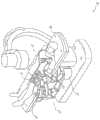
图21A示出了机器人臂201的远侧部分的三个视图,而图21B示出了机器人臂201的在图21A的远侧部分近侧的一部分的三个视图。参考图21A和图21B,机器人臂201可包括装置操纵器203、多个连杆205、207、209和211以及连接装置操纵器203和连杆205-211的多个接头213、215、217和219。在图21A所示的视图中的每个视图中,突出显示了机器人臂201的具有与患者碰撞的相对较高的可能性的区域221。FIG. 21A shows three views of a distal portion of
本公开的各方面涉及能够感测与外部对象(诸如患者、床边工作人员或其他对象)的接触的臂部件(例如,图21A至图21B的机器人连杆205-211或接头213-219中的一者)。Aspects of the present disclosure relate to arm components (eg, in robotic links 205-211 or joints 213-219 of FIGS. 21A-21B ) capable of sensing contact with external objects, such as patients, bedside staff, or other objects one of the).
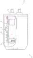
在某些具体实施中,外壳可以悬挂在给定连杆周围,并且外壳与连杆的内部部件/构件之间的相对运动可以使用一个或多个传感器来进行检测,以便检测与外部对象的接触。图22示出了根据本公开的各方面的包括刚性外壳309并且被构造成检测与外部对象的接触的示例性连杆300。具体地,连杆300包括结构连杆301、结构盖303、第一接头305、第二接头307、外壳309、一对反作用桨311和外壳盖313。例如,连杆300的内部部件可包括结构连杆301和结构盖303。In some implementations, a housing can be suspended around a given link, and relative motion between the housing and the internal components/members of the link can be detected using one or more sensors to detect contact with external objects . FIG. 22 illustrates an
结构盖303可以附接到结构连杆301以容纳结构连杆301的部件并且在第一接头305与第二连杆305之间形成内部结构连接。外壳309连同外壳盖313悬挂在结构连杆301上方并且围绕该结构连杆。如本文所用,除非上下文另外清楚地指示,否则外壳309和外壳盖313可以共同地被简称为“外壳”309,而结构连杆301和结构盖303可以共同地被简称为结构连杆301或可操纵连杆。
外壳309可经由力感测连接件连接到结构连杆301。因为外壳309围绕结构连杆301,所以当连杆300接触外部对象时,该对象将与外壳309接触。因此,力感测连接件可通过测量因连杆300与外部对象接触而引起的外壳309与结构连杆301之间的力的变化来检测外壳309与外部对象之间的接触。外壳309还可以是足够刚性的,使得在与外部对象接触时,外壳309接合力感测连接件。有利地,通过使用刚性外壳309,可以在所有的三个方向上感测外壳309与结构连杆301之间的力和相对移动。Housing 309 may be connected to
根据本公开的各方面,力感测连接件可以以多种不同的方式实施。例如,力感测连接件可包括以下各者中的一者或多者:传统负荷传感器、力感测电阻器和/或能够感测力(或位移,当与弹簧组合时)的任何部件。According to aspects of the present disclosure, a force-sensing link may be implemented in a number of different ways. For example, a force-sensing connection may include one or more of a conventional load sensor, a force-sensing resistor, and/or any component capable of sensing force (or displacement, when combined with a spring).
图23示出了根据本公开的各方面的可用于图22的连杆300中的力感测连接件的一个示例。具体地,力感测连接件可包括多个外壳传感器321(例如,在例示的实施方案中为十四个外壳传感器),这些外壳传感器可设置在结构连杆301与外壳309之间。FIG. 23 illustrates one example of a force sensing connection that may be used in the
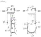
在一些实施方案中,传感器321在外壳309与结构连杆301之间遍布于连杆300上。例如,外壳309可经由传感器321悬挂在结构连杆301上方。根据具体实施,连杆300可包括沿着机器人臂连杆分布的一个、两个、三个、四个或更多个传感器321。图24A示出了根据本公开的各方面的在连杆401中包括十四个传感器321的实施方案的两个视图。具体地,图24A示出了包括七个传感器321的连杆401的一端的侧视图和前视图。连杆401可在连杆401的两端基本上对称,从而在连杆401中包括总共十四个传感器321。In some embodiments,
图24B示出了根据本公开的各方面的在连杆411中包括十二个传感器321的实施方案的两个视图。在一些具体实施中,机器人臂可包括连杆401和连杆411,其中连杆401被定位为靠近连杆411。具体地,图24B示出了包括十二个传感器321的连杆411的侧视图和前视图。连杆401可在连杆401的两端基本上对称,从而在连杆401中包括总共十四个传感器321。在多种具体实施中,多个传感器321可以被构造成支撑刚性外壳而不固定到刚性外壳。在一些具体实施中,连杆401、411还可包括一个或多个支撑件,该一个或多个支撑件被构造成相对于结构连杆支撑刚性外壳。例如,一个或多个支撑件可包括弹簧、挠曲件和/或悬架。Figure 24B shows two views of an embodiment including twelve
尽管图24A和图24B示出了包括多个传感器321的连杆401、411的实施方案,但是在其他具体实施中,连杆可包括被配置成在多个方向上感测结构连杆301与外壳309之间的力和/或位移的单个传感器。使用从传感器321接收到的信号,机器人系统可被配置成检测外壳309与外部对象之间的接触的方向。机器人系统还可基于来自传感器321的信号来测量由外壳309与外部对象之间的接触引起的力的大小。基于多个传感器321在连杆401和411内的放置,机器人系统还可被配置成检测施加到连杆的扭矩。例如,如果将扭矩施加到外壳309,则在连杆401、411的一侧上的某些传感器321可被压缩。基于被压缩的传感器321的方位和由该传感器感测的力,机器人系统可确定施加到连杆401、411的扭矩。Although FIGS. 24A and 24B illustrate embodiments of
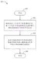
图25是示出了根据本公开的一个或多个方面的可由外科机器人系统或其部件操作的用于检测机器人臂/操纵器与外部对象之间的接触的示例性方法500的流程图。应当理解,图25所示的方法500的步骤可由外科机器人系统的一个或多个处理器执行。为了方便起见,方法500被描述为由系统的处理器执行。25 is a flowchart illustrating an example method 500 operable by a surgical robotic system or components thereof for detecting contact between a robotic arm/manipulator and an external object, according to one or more aspects of the present disclosure. It should be understood that the steps of method 500 shown in FIG. 25 may be performed by one or more processors of the surgical robotic system. For convenience, method 500 is described as being performed by a processor of the system.
处理器可以被包括进来作为系统的一部分,该系统包括机器人操纵器,该机器人操纵器包括连杆、被构造成覆盖该连杆的刚性外壳和被定位在刚性外壳与连杆之间的一个或多个传感器。该一个或多个传感器被配置成在至少两个或更多个方向上检测一个或多个外部对象与刚性外壳之间的接触。该系统还可包括至少一个计算机可读存储器,该计算机可读存储器与处理器通信并且在其上存储有计算机可执行指令以致使处理器集合执行方法500。The processor may be included as part of a system that includes a robotic manipulator including a linkage, a rigid housing configured to cover the linkage, and one or Multiple sensors. The one or more sensors are configured to detect contact between the one or more external objects and the rigid housing in at least two or more directions. The system may also include at least one computer-readable memory in communication with the processors and having computer-executable instructions stored thereon to cause the set of processors to perform the method 500 .
方法500可在框501处开始。在框502处,处理器可接收来自一个或多个传感器的信号,该一个或多个传感器被定位在机器人操纵器的可操纵连杆与被构造成覆盖连杆的刚性外壳之间。接收到的信号指示刚性外壳与一个或多个传感器之间的接触程度。Method 500 may begin at block 501 . At block 502, a processor may receive a signal from one or more sensors positioned between a steerable link of a robotic manipulator and a rigid housing configured to cover the link. The received signal is indicative of the degree of contact between the rigid housing and the one or more sensors.
在框504处,处理器可响应于接收到的信号满足或超过阈值而确定机器人操纵器与外部对象之间的接触已发生。在一些具体实施中,处理器还可基于接收到的信号来检测刚性外壳与外部对象之间的接触的方向。处理器还可基于从一个或多个传感器接收到的信号中的信息(例如,时域或频域中的数据)来测量由刚性外壳与外部对象之间的接触引起的力和/或扭矩的大小。处理器还可被配置成基于接收到的信号来测量刚性外壳与连杆之间的相对运动的方向。At block 504, the processor may determine that contact between the robotic manipulator and the external object has occurred in response to the received signal meeting or exceeding a threshold. In some implementations, the processor can also detect a direction of contact between the rigid housing and the external object based on the received signal. The processor may also measure, based on information in signals received from the one or more sensors (e.g., data in the time or frequency domain) the force and/or torque resulting from contact between the rigid housing and the external object. size. The processor may also be configured to measure a direction of relative motion between the rigid housing and the linkage based on the received signal.
在某些实施方案中,处理器还可被配置成基于来自传感器的指示检测到的接触的信号来确定外部对象在空间中的位置,并且通过更新碰撞模型来防止机器人臂(或其他机器人臂)移动到接触的位置,以避免在相同区域中的未来接触。这样的信息可包括通过由给定传感器检测到的接触和/或方向信息来激活哪些传感器。如本文所用,碰撞模型可以是可处于与机器人臂碰撞的风险下的环境内的对象的模型。机器人系统可防止机器人臂的移动,该移动将导致与在碰撞模型中建模的对象的碰撞。方法500可在框506处结束。In some embodiments, the processor may also be configured to determine the position of the external object in space based on the signal from the sensor indicating the detected contact, and to prevent the robotic arm (or other robotic arm) from Move to the location of contact to avoid future contact in the same area. Such information may include which sensors are activated by contact and/or orientation information detected by a given sensor. As used herein, a collision model may be a model of objects within an environment that may be at risk of collision with a robotic arm. The robotic system prevents movements of the robotic arm that would cause collisions with objects modeled in the collision model. Method 500 may end at block 506 .
设置在连杆300、401或411中的一个或多个传感器321可包括:传统负荷传感器、力感测电阻器、应变仪和/或电容传感器等。在一个具体实施中,一个或多个传感器321包括梁挠曲件型传感器600(也被称为弹簧或跳板传感器)。图26示出了根据本公开的各方面的梁挠曲件传感器600的实施方案。在该具体实施中,传感器600包括被构造成接触下面的力传感器603的梁挠曲件601。在将力施加到外壳309时,外壳通过梁挠曲件601将力施加到传感器,该梁挠曲件然后将力施加到力传感器603(其可从原始力进行缩放)。因此,这类运动(其可包括微运动)将允许传感器603检测与外部对象的接触已发生。基于与外部对象的接触的检测,机器人系统可以采取动作(例如,停止机器人臂的运动)以减少接触或防止进一步的接触。The one or
图27示出了根据本公开的各方面的梁挠曲件传感器700的另一实施方案。在该具体实施中,传感器700包括被构造成接触下面的力传感器703的梁挠曲件701和该梁挠曲件701被构造成接触外壳309的接触点705。尽管未示出,但是传感器700还可包括电路板,该电路板被配置成接收来自力传感器703的输出信号并且输出指示施加到接触点705的力的信号。在一些具体实施中,力传感器703可安装于电路板上。梁挠曲件701可包括固定的第一端(例如,在图27的左侧)和联接到力传感器703的第二端(例如,在图27的右侧)。接触点705位于梁挠曲件701的第一端与第二端之间。因此,施加于力传感器703上的力与施加到接触点705的力成比例或以其他方式指示施加到该接触点的力。与接触点705结合,梁挠曲件701可被配置成缩放施加到传感器700的力并且将传感器703与施加到外壳309的剪切力隔离。在某些具体实施中,接触点705可用作负荷集中器,该负荷集中器被配置成控制外壳309将力施加到传感器700的点(例如,将力施加到梁挠曲件701的点)。FIG. 27 illustrates another embodiment of a
第一端与第二端之间的接触点705的特定位置将影响由外部对象与外壳309的接触提供到力传感器703上的杠杆作用的量。例如,当接触点705更靠近具有力传感器703的第二端定位时,与在接触点705更靠近固定的第一端定位时的情况相比,施加到接触点705的更多的力将被传递到力传感器703。因此,可选择接触点705的位置以将预期由外壳309接收的力的范围映射到可由力传感器703检测的力的范围上。通过使用梁挠曲件701来减小力,力传感器703可通过将接收到的力减小到可由力传感器703测量的力的范围上来有效地测量施加到外壳309的更大的力。The particular location of the
本公开的各方面提供了用于检测连杆与外部对象之间的接触的多个优点。例如,本公开的各方面优于测量扭矩(利用扭矩传感器直接测量,或通过电流或控制回路扰动测量)的系统,这是因为本公开的具体实施的灵敏度不会随着所施加的力矢量接近扭矩轴线而降低,如在扭矩感测系统中的情况。类似地,将整个机器人安装在负荷传感器上的系统(如在一些工业机器人中常见的)可具有与基于扭矩的测量系统类似的缺点。Aspects of the present disclosure provide several advantages for detecting contact between a linkage and an external object. For example, aspects of the present disclosure are advantageous over systems that measure torque (either directly with a torque sensor, or through current or control loop perturbations) because the sensitivity of an implementation of the present disclosure does not increase as the applied force vector approaches torque axis, as is the case in torque sensing systems. Similarly, systems in which the entire robot is mounted on load cells (as is common in some industrial robots) can have similar disadvantages as torque-based measurement systems.
另外,如本文所述,通过使用外壳309来检测与外部对象的接触,系统可有利地感测在连杆的整个表面上的接触。相比之下,采用膜来感测接触的具体实施可能无法感测或检测在膜未被应用于连杆的位置处与外部对象的接触。Additionally, by using housing 309 to detect contact with external objects, as described herein, the system may advantageously sense contact over the entire surface of the linkage. In contrast, implementations that employ a membrane to sense contact may not be able to sense or detect contact with external objects at locations where the membrane is not applied to the linkage.
本公开的各方面的另一优点包括允许系统感测给定连杆的整个表面上的接触力的总量,以允许一定量的轻微的偶然接触而不中断医疗规程。这优于无法区分少量的偶然力与具有损伤和/或损坏风险的更大的力的系统。Another advantage of aspects of the present disclosure includes allowing the system to sense the total amount of contact force across the entire surface of a given linkage to allow a certain amount of slight incidental contact without disrupting medical procedures. This is superior to systems that cannot distinguish between small occasional forces and larger forces with risk of injury and/or damage.
本公开的各方面的又一优点是与在压敏充气囊中围绕机器人的系统相比,由外壳实现的紧凑形状因子。Yet another advantage of aspects of the present disclosure is the compact form factor achieved by the enclosure compared to systems that surround the robot in a pressure sensitive inflatable bladder.
使用膜的接触检测Contact Detection Using Membrane
在某些具体实施中,传感器的涂层或膜可粘附到连杆(例如,机器人臂连杆)的表面。图28示出了根据本公开的各方面的可形成机器人臂的一部分的示例性机器人连杆800。具体地,连杆800包括结构连杆801和施加到结构连杆801的外表面的膜803。根据具体实施,膜803可包括各种类型的力传感器。例如,可在膜803中使用的技术包括:力感测电阻器(FSR)、电容传感器、接近传感器等。In some implementations, a coating or film of a sensor can be adhered to the surface of a link (eg, a robotic arm link). FIG. 28 illustrates an example
在某些具体实施中,膜803可以附接到连杆800的更有可能接触外部对象的表面(例如,图21A和图21B所示的区域221)。通过使用膜803检测与外部对象的接触,机器人系统可对检测到的接触作出响应,以防止将不可接受地高负荷施加到外部对象(例如,无生命对象,诸如医疗配件或床、床边工作人员或患者)上。In some implementations,
通过将这样的膜803应用于机器人臂,机器人系统可检测外部对象与机器人臂之间的接触,并且防止在与外部对象接触的方向上的进一步移动。此外,机器人系统还可基于检测到的接触来确定外部对象在空间中的位置,并且通过更新碰撞模型来防止机器人臂(或其他机器人臂)移动到接触的位置,以避免在相同区域中的未来接触。机器人系统可防止机器人臂的移动,该移动将导致与在碰撞模型中建模的对象的碰撞。By applying such a
根据本公开的各方面的力感测膜803的使用通过在机器人(例如,机器人臂)与外部对象碰撞,然后停止之前一直允许该机器人移动来允许机器人的无碰撞工作空间的最大化。这允许比在结构连杆(例如,在压敏充气囊中围绕机器人的系统)周围占据更大体积的力感测解决方案的情况下可能以其他方式可行的工作空间更大的工作空间。The use of
与使用定位在机器人臂接头中的力或扭矩传感器的系统相比,本公开的采用力感测膜的各方面不会随着所施加的力矢量接近扭矩轴线而经历减小,如在扭矩感测系统中的情况。类似地,将整个机器人安装在负荷传感器上的系统(如在一些工业机器人中常见的)可具有与基于扭矩的测量系统类似的缺点。In contrast to systems using force or torque sensors positioned in a robotic arm joint, aspects of the present disclosure employing a force-sensing membrane do not experience a decrease in torque sense as the applied force vector approaches the torque axis. conditions in the system. Similarly, systems in which the entire robot is mounted on load cells (as is common in some industrial robots) can have similar disadvantages as torque-based measurement systems.
与人工地限制机器人的工作空间使得其永远不会接触患者或配件的系统相比,增加的无碰撞工作空间的优点也是明显的。由于这类人工限制不能精确地限定外部对象的位置,因此使用这类人工限制的具体实施可显著地限制工作空间并且由于机器人臂的不可实现的移动和/或姿势而引起用户疼痛。在相关方面,力感测膜803可与设置在可操纵连杆中的一个或多个传感器321结合使用,其中一个或多个传感器可包括:传统负荷传感器、力感测电阻器、应变仪和/或电容传感器等。The advantage of the increased collision-free workspace is also significant compared to systems where the robot's workspace is artificially limited such that it never touches the patient or accessories. Implementations using such artificial constraints can significantly restrict the workspace and cause user pain due to unrealizable movements and/or poses of the robot arm, since such artificial constraints cannot precisely define the position of external objects. In a related aspect, the force-sensing
4.实施系统和术语。4. Implement systems and terminology .
本文所公开的具体实施提供了用于检测连杆与外部对象之间的接触的系统、方法和装置。Embodiments disclosed herein provide systems, methods, and devices for detecting contact between a linkage and an external object.
应当指出的是,如本文所用,术语“联接”或词语联接的其他变型形式可以指示间接连接或直接连接。例如,如果第一部件“联接”到第二部件,则第一部件可经由另一个部件间接连接到第二部件或直接连接到第二部件。It should be noted that, as used herein, the term "coupled" or other variations of the word coupled may indicate an indirect connection or a direct connection. For example, if a first component is "coupled" to a second component, the first component may be indirectly connected to the second component via another component or directly connected to the second component.
本文所述的连杆与外部对象功能之间的接触的检测可作为一个或多个指令存储在处理器可读或计算机可读介质上。术语“计算机可读介质”是指可由计算机或处理器访问的任何可用介质。通过示例而非限制,此类介质可包括随机存取存储器(RAM)、只读存储器(ROM)、电可擦除可编程只读存储器(EEPROM)、快闪存储器、致密盘只读存储器(CD-ROM)或其他光盘存储装置、磁盘存储装置或其他磁存储装置,或可以用于存储呈指令或数据结构的形式的期望的程序代码并且可以由计算机访问的任何其他介质。应当指出的是,计算机可读介质可为有形的和非暂态的。如本文所用,术语“代码”可以指可由计算装置或处理器执行的软件、指令、代码或数据。The detection of contact between a linkage and an external object function as described herein may be stored as one or more instructions on a processor-readable or computer-readable medium. The term "computer-readable medium" refers to any available medium that can be accessed by a computer or processor. By way of example and not limitation, such media may include random access memory (RAM), read only memory (ROM), electrically erasable programmable read only memory (EEPROM), flash memory, compact disk read only memory (CD - ROM) or other optical disk storage, magnetic disk storage, or other magnetic storage, or any other medium that can be used to store desired program code in the form of instructions or data structures and that can be accessed by a computer. It should be noted that computer readable media may be tangible and non-transitory. As used herein, the term "code" may refer to software, instructions, code or data executable by a computing device or processor.
本文所公开的方法包括用于实现所述方法的一个或多个步骤或动作。在不脱离权利要求的范围的情况下,方法步骤和/或动作可彼此互换。换句话讲,除非正在描述的方法的正确操作需要步骤或动作的特定顺序,否则可以在不脱离权利要求的范围的情况下修改特定步骤和/或动作的顺序和/或使用。A method disclosed herein includes one or more steps or actions for carrying out the method. The method steps and/or actions may be interchanged with one another without departing from the scope of the claims. In other words, unless a specific order of steps or actions is required for correct operation of the method being described, the order and/or use of specific steps and/or actions may be modified without departing from the scope of the claims.
如本文所用,术语“多个”表示两个或更多个。例如,多个部件指示两个或更多个部件。术语“确定”涵盖多种动作,并且因此,“确定”可包括计算、运算、处理、导出、调查、查找(例如,在表格、数据库或另一种数据结构中查找)、查明等。另外,“确定”可包括接收(例如,接收信息)、访问(例如,访问存储器中的数据)等。另外,“确定”可包括解析、选择、挑选、建立等。As used herein, the term "plurality" means two or more. For example, a plurality of components indicates two or more components. The term "determining" encompasses a variety of actions, and thus, "determining" may include computing, computing, processing, deriving, investigating, looking up (eg, in a table, database, or another data structure), ascertaining, and the like. Additionally, "determining" may include receiving (eg, receiving information), accessing (eg, accessing data in a memory), and the like. Additionally, "determining" may include resolving, selecting, selecting, establishing, and the like.
除非另有明确指明,否则短语“基于”并不意味着“仅基于”。换句话讲,短语“基于”描述“仅基于”和“至少基于”两者。The phrase "based on" does not mean "based only on" unless expressly stated otherwise. In other words, the phrase "based on" describes both "based only on" and "based on at least".
提供对所公开的具体实施的前述描述以使得本领域的任何技术人员能够制作或使用本发明。对这些具体实施的各种修改对于本领域的技术人员而言将是显而易见的,并且在不脱离本发明的范围的情况下,本文所定义的一般原理可应用于其他具体实施。例如,应当理解,本领域的普通技术人员将能够采用多个对应的替代和等同的结构细节,诸如紧固、安装、联接或接合工具部件的等同方式、用于产生特定致动运动的等同机构、以及用于递送电能的等同机构。因此,本发明并非旨在限于本文所示的具体实施,而是被赋予符合本文所公开的原理和新颖特征的最广范围。The foregoing description of the disclosed implementations is provided to enable any person skilled in the art to make or use the invention. Various modifications to these implementations will be readily apparent to those skilled in the art, and the generic principles defined herein may be applied to other implementations without departing from the scope of the invention. For example, it should be understood that those of ordinary skill in the art will be able to employ a number of corresponding alternative and equivalent structural details, such as equivalent means of fastening, mounting, coupling or engaging tool parts, equivalent mechanisms for producing specific actuating movements , and equivalent mechanisms for delivering electrical energy. Thus, the invention is not intended to be limited to the particular implementations shown herein but is to be accorded the widest scope consistent with the principles and novel features disclosed herein.
Claims (21)
Translated fromChineseApplications Claiming Priority (3)
| Application Number | Priority Date | Filing Date | Title |
|---|---|---|---|
| US202063045351P | 2020-06-29 | 2020-06-29 | |
| US63/045351 | 2020-06-29 | ||
| PCT/IB2021/055496WO2022003485A1 (en) | 2020-06-29 | 2021-06-22 | Systems and methods for detecting contact between a link and an external object |
Publications (1)
| Publication Number | Publication Date |
|---|---|
| CN115802975Atrue CN115802975A (en) | 2023-03-14 |
Family
ID=79032222
Family Applications (1)
| Application Number | Title | Priority Date | Filing Date |
|---|---|---|---|
| CN202180047190.0APendingCN115802975A (en) | 2020-06-29 | 2021-06-22 | System and method for detecting contact between a connecting rod and an external object |
Country Status (4)
| Country | Link |
|---|---|
| US (3) | US11839969B2 (en) |
| EP (1) | EP4171427A4 (en) |
| CN (1) | CN115802975A (en) |
| WO (1) | WO2022003485A1 (en) |
Families Citing this family (1)
| Publication number | Priority date | Publication date | Assignee | Title |
|---|---|---|---|---|
| US11993498B2 (en)* | 2021-10-28 | 2024-05-28 | Toyota Research Institute, Inc. | Structures and sensor assemblies having engagement structures for securing a compliant substrate assembly |
Citations (4)
| Publication number | Priority date | Publication date | Assignee | Title |
|---|---|---|---|---|
| US20110029133A1 (en)* | 2008-06-06 | 2011-02-03 | Yasunao Okazaki | Robot, and control apparatus, control method, and control program for robot |
| CN109099950A (en)* | 2017-06-21 | 2018-12-28 | 奥普托塞斯股份有限公司 | Proximity sensor |
| CN110139619A (en)* | 2017-02-15 | 2019-08-16 | 柯惠Lp公司 | Anti-Crush Systems and Devices for Medical Robotics Applications |
| KR20190120838A (en)* | 2018-04-12 | 2019-10-25 | 한국기계연구원 | Robot manipulator |
Family Cites Families (500)
| Publication number | Priority date | Publication date | Assignee | Title |
|---|---|---|---|---|
| US3763860A (en) | 1971-08-26 | 1973-10-09 | H Clarke | Laparoscopy instruments and method for suturing and ligation |
| US4040413A (en) | 1974-07-18 | 1977-08-09 | Fuji Photo Optical Co. Ltd. | Endoscope |
| JPS5394515A (en) | 1977-01-31 | 1978-08-18 | Kubota Ltd | Method of producing glass fiber reinforced cement plate |
| US4470407A (en) | 1982-03-11 | 1984-09-11 | Laserscope, Inc. | Endoscopic device |
| US4532935A (en) | 1982-11-01 | 1985-08-06 | Wang Ko P | Bronchoscopic needle assembly |
| US4747405A (en) | 1984-03-01 | 1988-05-31 | Vaser, Inc. | Angioplasty catheter |
| US4685458A (en) | 1984-03-01 | 1987-08-11 | Vaser, Inc. | Angioplasty catheter and method for use thereof |
| DE3715418A1 (en) | 1986-05-08 | 1987-11-12 | Olympus Optical Co | LITHOTOM |
| US4854301A (en) | 1986-11-13 | 1989-08-08 | Olympus Optical Co., Ltd. | Endoscope apparatus having a chair with a switch |
| US5029574A (en) | 1988-04-14 | 1991-07-09 | Okamoto Industries, Inc. | Endoscopic balloon with a protective film thereon |
| DE68917895T2 (en) | 1988-06-06 | 1995-02-02 | Sumitomo Electric Industries | CATHETER. |
| EP0347098B1 (en) | 1988-06-13 | 1996-02-28 | Samuel Shiber | Atherectomy system with a guide-wire |
| US5150452A (en) | 1989-07-28 | 1992-09-22 | Megamation Incorporated | Method and apparatus for anti-collision and collision protection for multiple robot system |
| US5344395A (en) | 1989-11-13 | 1994-09-06 | Scimed Life Systems, Inc. | Apparatus for intravascular cavitation or delivery of low frequency mechanical energy |
| US4983165A (en) | 1990-01-23 | 1991-01-08 | Loiterman David A | Guidance system for vascular catheter or the like |
| DE9001262U1 (en) | 1990-02-05 | 1990-08-09 | Martin, Werner, 7207 Rietheim-Weilheim | Surgical needle holder for an endo-suture, endo-ligature or similar. |
| US5345927A (en) | 1990-03-02 | 1994-09-13 | Bonutti Peter M | Arthroscopic retractors |
| CA2048120A1 (en) | 1990-08-06 | 1992-02-07 | William J. Drasler | Thrombectomy method and device |
| US5496267A (en) | 1990-11-08 | 1996-03-05 | Possis Medical, Inc. | Asymmetric water jet atherectomy |
| US5085659A (en) | 1990-11-21 | 1992-02-04 | Everest Medical Corporation | Biopsy device with bipolar coagulation capability |
| US5199417A (en) | 1990-12-21 | 1993-04-06 | Circon Corporation | Endoscope having a deflectable distal section and a semi-rigid proximal section |
| JPH05208014A (en) | 1991-04-10 | 1993-08-20 | Olympus Optical Co Ltd | Treating tool |
| JP3307392B2 (en) | 1991-05-29 | 2002-07-24 | オリジン・メドシステムズ・インク | Endoscope retraction device for surgery |
| US5417210A (en) | 1992-05-27 | 1995-05-23 | International Business Machines Corporation | System and method for augmentation of endoscopic surgery |
| US5279309A (en) | 1991-06-13 | 1994-01-18 | International Business Machines Corporation | Signaling device and method for monitoring positions in a surgical operation |
| US5269797A (en) | 1991-09-12 | 1993-12-14 | Meditron Devices, Inc. | Cervical discectomy instruments |
| US5449356A (en) | 1991-10-18 | 1995-09-12 | Birtcher Medical Systems, Inc. | Multifunctional probe for minimally invasive surgery |
| US5217001A (en) | 1991-12-09 | 1993-06-08 | Nakao Naomi L | Endoscope sheath and related method |
| US5217465A (en) | 1992-02-28 | 1993-06-08 | Alcon Surgical, Inc. | Flexible and steerable aspiration tip for microsurgery |
| US5737500A (en)* | 1992-03-11 | 1998-04-07 | California Institute Of Technology | Mobile dexterous siren degree of freedom robot arm with real-time control system |
| US5318589A (en) | 1992-04-15 | 1994-06-07 | Microsurge, Inc. | Surgical instrument for endoscopic surgery |
| US5325848A (en) | 1992-09-10 | 1994-07-05 | Ethicon, Inc. | Endoscopic tissue manipulator with expandable frame |
| US5545170A (en) | 1992-10-09 | 1996-08-13 | Innovasive Devices, Inc. | Surgical instrument |
| US5342381A (en) | 1993-02-11 | 1994-08-30 | Everest Medical Corporation | Combination bipolar scissors and forceps instrument |
| JP3587848B2 (en) | 1993-06-10 | 2004-11-10 | ミア エイ イムラン | Transurethral RF resection device |
| US5792165A (en) | 1993-07-21 | 1998-08-11 | Charles H. Klieman | Endoscopic instrument with detachable end effector |
| US5431649A (en) | 1993-08-27 | 1995-07-11 | Medtronic, Inc. | Method and apparatus for R-F ablation |
| US5876325A (en) | 1993-11-02 | 1999-03-02 | Olympus Optical Co., Ltd. | Surgical manipulation system |
| US5645083A (en) | 1994-02-10 | 1997-07-08 | Essig; Mitchell N. | Peritoneal surgical method |
| US5411016A (en) | 1994-02-22 | 1995-05-02 | Scimed Life Systems, Inc. | Intravascular balloon catheter for use in combination with an angioscope |
| US5441485A (en) | 1994-02-24 | 1995-08-15 | Peters; Michael J. | Bladder catheter |
| US5501667A (en) | 1994-03-15 | 1996-03-26 | Cordis Corporation | Perfusion balloon and method of use and manufacture |
| US5529235A (en) | 1994-04-28 | 1996-06-25 | Ethicon Endo-Surgery, Inc. | Identification device for surgical instrument |
| EP0699418A1 (en) | 1994-08-05 | 1996-03-06 | United States Surgical Corporation | Self-contained powered surgical apparatus |
| US5573535A (en) | 1994-09-23 | 1996-11-12 | United States Surgical Corporation | Bipolar surgical instrument for coagulation and cutting |
| US5798627A (en) | 1995-01-04 | 1998-08-25 | Gilliland; Malcolm T. | Method for simultaneous operation of robot welders |
| US5613973A (en) | 1995-03-10 | 1997-03-25 | Wilson Greatbatch Ltd. | Laraposcopic surgical grasper having an attachable strap |
| US5562648A (en) | 1995-03-31 | 1996-10-08 | E. I. Du Pont De Nemours And Company | Adult incontinent absorbent undergarment |
| US5697949A (en) | 1995-05-18 | 1997-12-16 | Symbiosis Corporation | Small diameter endoscopic instruments |
| US5562678A (en) | 1995-06-02 | 1996-10-08 | Cook Pacemaker Corporation | Needle's eye snare |
| JP2915826B2 (en) | 1995-07-11 | 1999-07-05 | 富士通株式会社 | Interference check device |
| DE19532098A1 (en) | 1995-08-30 | 1997-03-06 | Stuemed Gmbh | Device for endoscopic operations, in particular an expandable support epi-hypopharyngo-laryngoscope according to Feyh-Kastenbauer |
| US5710870A (en) | 1995-09-07 | 1998-01-20 | California Institute Of Technology | Decoupled six degree-of-freedom robot manipulator |
| US5989230A (en) | 1996-01-11 | 1999-11-23 | Essex Technology, Inc. | Rotate to advance catheterization system |
| US5624398A (en) | 1996-02-08 | 1997-04-29 | Symbiosis Corporation | Endoscopic robotic surgical tools and methods |
| DE69634385D1 (en) | 1996-05-10 | 2005-03-31 | Emmanuil Giannadakis | SYSTEM FOR LAPAROSCOPIC AND ENDOSCOPIC SURGERY |
| US5797900A (en) | 1996-05-20 | 1998-08-25 | Intuitive Surgical, Inc. | Wrist mechanism for surgical instrument for performing minimally invasive surgery with enhanced dexterity and sensitivity |
| US5658311A (en) | 1996-07-05 | 1997-08-19 | Schneider (Usa) Inc. | High pressure expander bundle for large diameter stent deployment |
| US5788667A (en) | 1996-07-19 | 1998-08-04 | Stoller; Glenn | Fluid jet vitrectomy device and method for use |
| US7727244B2 (en) | 1997-11-21 | 2010-06-01 | Intuitive Surgical Operation, Inc. | Sterile surgical drape |
| US6331181B1 (en) | 1998-12-08 | 2001-12-18 | Intuitive Surgical, Inc. | Surgical robotic tools, data architecture, and use |
| US5810770A (en) | 1996-12-13 | 1998-09-22 | Stryker Corporation | Fluid management pump system for surgical procedures |
| US5893869A (en) | 1997-02-19 | 1999-04-13 | University Of Iowa Research Foundation | Retrievable inferior vena cava filter system and method for use thereof |
| CA2287971C (en) | 1997-04-29 | 2007-04-24 | Raymond F. Lippitt | Annularly expanding and retracting gripping and releasing mechanism |
| US6156030A (en) | 1997-06-04 | 2000-12-05 | Y-Beam Technologies, Inc. | Method and apparatus for high precision variable rate material removal and modification |
| US6231565B1 (en) | 1997-06-18 | 2001-05-15 | United States Surgical Corporation | Robotic arm DLUs for performing surgical tasks |
| US6174318B1 (en) | 1998-04-23 | 2001-01-16 | Scimed Life Systems, Inc. | Basket with one or more moveable legs |
| US6071281A (en) | 1998-05-05 | 2000-06-06 | Ep Technologies, Inc. | Surgical method and apparatus for positioning a diagnostic or therapeutic element within the body and remote power control unit for use with same |
| US6093157A (en) | 1997-10-22 | 2000-07-25 | Scimed Life Systems, Inc. | Radiopaque guide wire |
| US6120476A (en) | 1997-12-01 | 2000-09-19 | Cordis Webster, Inc. | Irrigated tip catheter |
| RU2130762C1 (en) | 1997-12-10 | 1999-05-27 | Федоров Святослав Николаевич | Device for performing ophthalmosurgical operations |
| US6120498A (en) | 1998-03-05 | 2000-09-19 | Jani; Mahendra G. | Aspirating handpieces for laser surgical operations |
| DE19814630B4 (en) | 1998-03-26 | 2011-09-29 | Carl Zeiss | Method and apparatus for manually controlled guiding a tool in a predetermined range of motion |
| FR2779934B1 (en) | 1998-06-17 | 2001-01-05 | Saphir Medical Sa | PNEUMATICALLY CONTROLLED HANDPIECE FOR SURGICAL AND MEDICAL APPLICATIONS |
| US6459926B1 (en)* | 1998-11-20 | 2002-10-01 | Intuitive Surgical, Inc. | Repositioning and reorientation of master/slave relationship in minimally invasive telesurgery |
| US6659939B2 (en) | 1998-11-20 | 2003-12-09 | Intuitive Surgical, Inc. | Cooperative minimally invasive telesurgical system |
| US6398726B1 (en) | 1998-11-20 | 2002-06-04 | Intuitive Surgical, Inc. | Stabilizer for robotic beating-heart surgery |
| US8600551B2 (en) | 1998-11-20 | 2013-12-03 | Intuitive Surgical Operations, Inc. | Medical robotic system with operatively couplable simulator unit for surgeon training |
| US6522906B1 (en) | 1998-12-08 | 2003-02-18 | Intuitive Surgical, Inc. | Devices and methods for presenting and regulating auxiliary information on an image display of a telesurgical system to assist an operator in performing a surgical procedure |
| DE19859434C2 (en) | 1998-12-22 | 2001-03-08 | Bruker Optik Gmbh | IR spectroscopic endoscope with inflatable balloon |
| US6405078B1 (en) | 1999-01-15 | 2002-06-11 | Biosense Webster, Inc. | Porous irrigated tip electrode catheter |
| US6394998B1 (en) | 1999-01-22 | 2002-05-28 | Intuitive Surgical, Inc. | Surgical tools for use in minimally invasive telesurgical applications |
| US6110171A (en) | 1999-03-09 | 2000-08-29 | Everest Medical Corporation | Electrosurgical cutting and coagulating instrument for open surgery |
| CN1352538A (en) | 1999-03-09 | 2002-06-05 | 先进警戒股份有限公司 | Biopsy device and method of obtaining a biopsy sample |
| US6183435B1 (en) | 1999-03-22 | 2001-02-06 | Cordis Webster, Inc. | Multi-directional steerable catheters and control handles |
| US6911026B1 (en) | 1999-07-12 | 2005-06-28 | Stereotaxis, Inc. | Magnetically guided atherectomy |
| US6375635B1 (en) | 1999-05-18 | 2002-04-23 | Hydrocision, Inc. | Fluid jet surgical instruments |
| US8004229B2 (en) | 2005-05-19 | 2011-08-23 | Intuitive Surgical Operations, Inc. | Software center and highly configurable robotic systems for surgery and other uses |
| US9517106B2 (en) | 1999-09-17 | 2016-12-13 | Intuitive Surgical Operations, Inc. | Systems and methods for commanded reconfiguration of a surgical manipulator using the null-space |
| US9415510B2 (en) | 1999-09-17 | 2016-08-16 | Intuitive Surgical Operations, Inc. | System and methods for positioning a manipulator arm by clutching within a null-perpendicular space concurrent with null-space movement |
| US10029367B2 (en) | 1999-09-17 | 2018-07-24 | Intuitive Surgical Operations, Inc. | System and method for managing multiple null-space objectives and constraints |
| US9510911B2 (en) | 1999-09-17 | 2016-12-06 | Intuitive Surgical Operations, Inc. | System and methods for managing multiple null-space objectives and SLI behaviors |
| US6206903B1 (en) | 1999-10-08 | 2001-03-27 | Intuitive Surgical, Inc. | Surgical tool with mechanical advantage |
| US6491691B1 (en) | 1999-10-08 | 2002-12-10 | Intuitive Surgical, Inc. | Minimally invasive surgical hook apparatus and method for using same |
| US6440061B1 (en) | 2000-03-24 | 2002-08-27 | Donald E. Wenner | Laparoscopic instrument system for real-time biliary exploration and stone removal |
| US6942680B2 (en) | 2000-07-24 | 2005-09-13 | Jeffrey Grayzel | Stiffened balloon catheter for dilatation and stenting |
| US6746443B1 (en) | 2000-07-27 | 2004-06-08 | Intuitive Surgical Inc. | Roll-pitch-roll surgical tool |
| US20030158545A1 (en) | 2000-09-28 | 2003-08-21 | Arthrocare Corporation | Methods and apparatus for treating back pain |
| US6840938B1 (en) | 2000-12-29 | 2005-01-11 | Intuitive Surgical, Inc. | Bipolar cauterizing instrument |
| EP2335660B1 (en) | 2001-01-18 | 2018-03-28 | The Regents of The University of California | Minimally invasive glaucoma surgical instrument |
| US7699835B2 (en) | 2001-02-15 | 2010-04-20 | Hansen Medical, Inc. | Robotically controlled surgical instruments |
| JP4588906B2 (en) | 2001-03-13 | 2010-12-01 | オリンパス株式会社 | Endoscope collection tool |
| US7607440B2 (en)* | 2001-06-07 | 2009-10-27 | Intuitive Surgical, Inc. | Methods and apparatus for surgical planning |
| US20030004455A1 (en) | 2001-06-28 | 2003-01-02 | Kadziauskas Kenneth E. | Bi-manual phaco needle |
| US20060178556A1 (en) | 2001-06-29 | 2006-08-10 | Intuitive Surgical, Inc. | Articulate and swapable endoscope for a surgical robot |
| US6817974B2 (en) | 2001-06-29 | 2004-11-16 | Intuitive Surgical, Inc. | Surgical tool having positively positionable tendon-actuated multi-disk wrist joint |
| WO2003013374A1 (en) | 2001-08-06 | 2003-02-20 | Penn State Research Foundation | Multifunctional tool and method for minimally invasive surgery |
| US20030208189A1 (en) | 2001-10-19 | 2003-11-06 | Payman Gholam A. | Integrated system for correction of vision of the human eye |
| US6676668B2 (en) | 2001-12-12 | 2004-01-13 | C.R. Baed | Articulating stone basket |
| US6652537B2 (en) | 2001-12-12 | 2003-11-25 | C. R. Bard, Inc. | Articulating stone basket |
| DE10210646A1 (en) | 2002-03-11 | 2003-10-09 | Siemens Ag | Method for displaying a medical instrument brought into an examination area of a patient |
| EP1524940B1 (en) | 2002-03-19 | 2011-08-24 | Bard Dublin ITC Limited | Biopsy device and biopsy needle module that can be inserted into the biopsy device |
| DE10212154A1 (en) | 2002-03-19 | 2003-10-09 | Norbert F Heske | Handheld biopsy unit for the removal of tissue, comprises at least one tensioning and launching unit, and a needle unit with an outer hollow needle and a hollow biopsy needle |
| US20040158261A1 (en) | 2002-05-15 | 2004-08-12 | Vu Dinh Q. | Endoscopic device for spill-proof laparoscopic ovarian cystectomy |
| US8956280B2 (en) | 2002-05-30 | 2015-02-17 | Intuitive Surgical Operations, Inc. | Apparatus and methods for placing leads using direct visualization |
| AU2003257309A1 (en) | 2002-08-13 | 2004-02-25 | Microbotics Corporation | Microsurgical robot system |
| US20040176751A1 (en) | 2002-08-14 | 2004-09-09 | Endovia Medical, Inc. | Robotic medical instrument system |
| US20040186349A1 (en) | 2002-12-24 | 2004-09-23 | Usgi Medical Corp. | Apparatus and methods for achieving endoluminal access |
| US6984232B2 (en) | 2003-01-17 | 2006-01-10 | St. Jude Medical, Daig Division, Inc. | Ablation catheter assembly having a virtual electrode comprising portholes |
| US20040153093A1 (en) | 2003-01-31 | 2004-08-05 | Advanced Medical Optics, Inc. | Bi-manual phacoemulsification apparatus and method |
| US7559934B2 (en) | 2003-04-07 | 2009-07-14 | Scimed Life Systems, Inc. | Beaded basket retrieval device |
| US7122003B2 (en) | 2003-04-16 | 2006-10-17 | Granit Medical Innovations, Llc | Endoscopic retractor instrument and associated method |
| US7121781B2 (en) | 2003-06-11 | 2006-10-17 | Intuitive Surgical | Surgical instrument with a universal wrist |
| US9002518B2 (en) | 2003-06-30 | 2015-04-07 | Intuitive Surgical Operations, Inc. | Maximum torque driving of robotic surgical tools in robotic surgical systems |
| US8403828B2 (en) | 2003-07-21 | 2013-03-26 | Vanderbilt University | Ophthalmic orbital surgery apparatus and method and image-guide navigation system |
| US20050159645A1 (en) | 2003-11-12 | 2005-07-21 | Bertolero Arthur A. | Balloon catheter sheath |
| ITPI20030107A1 (en) | 2003-11-14 | 2005-05-15 | Massimo Bergamasco | DEVICE FOR PERFORMING OPERATIONS |
| EP1718193B1 (en) | 2004-02-09 | 2013-07-03 | Smart Medical Systems Ltd. | Endoscope assembly |
| US8021326B2 (en) | 2004-03-05 | 2011-09-20 | Hansen Medical, Inc. | Instrument driver for robotic catheter system |
| CA2561913A1 (en) | 2004-03-11 | 2005-09-22 | Medrad, Inc. | Energy assisted medical devices, systems and methods |
| US9345456B2 (en) | 2004-03-24 | 2016-05-24 | Devicor Medical Products, Inc. | Biopsy device |
| JP4638683B2 (en) | 2004-03-25 | 2011-02-23 | テルモ株式会社 | Intravascular foreign body removal aspiration catheter |
| US20050261705A1 (en) | 2004-05-21 | 2005-11-24 | Gist Christopher W | Device to remove kidney stones |
| JP2006061214A (en) | 2004-08-24 | 2006-03-09 | Olympus Corp | Surgery system |
| DE102004040959B4 (en) | 2004-08-24 | 2008-12-24 | Erbe Elektromedizin Gmbh | Surgical instrument |
| WO2006031596A2 (en) | 2004-09-09 | 2006-03-23 | Onset Medical Corporation | Expandable gastrointestinal sheath |
| US7824415B2 (en) | 2004-09-15 | 2010-11-02 | Boston Scientific Scimed, Inc. | Atraumatic medical device |
| US8827899B2 (en) | 2004-09-24 | 2014-09-09 | Vivid Medical, Inc. | Disposable endoscopic access device and portable display |
| US10646292B2 (en) | 2004-09-30 | 2020-05-12 | Intuitive Surgical Operations, Inc. | Electro-mechanical strap stack in robotic arms |
| US20060116693A1 (en) | 2004-12-01 | 2006-06-01 | Weisenburgh William B Ii | Apparatus and method for stone capture and removal |
| JP4982637B2 (en) | 2004-12-15 | 2012-07-25 | クック メディカル テクノロジーズ エルエルシー | Flexible surgical needle device |
| US20060156875A1 (en) | 2005-01-19 | 2006-07-20 | Depuy Mitek, Inc. | Fluid cutting device and method of use |
| US8375808B2 (en) | 2005-12-30 | 2013-02-19 | Intuitive Surgical Operations, Inc. | Force sensing for surgical instruments |
| US20080045981A1 (en) | 2005-04-22 | 2008-02-21 | Ilya Margolin | Ligating clip and ligating clip applicator |
| US9789608B2 (en) | 2006-06-29 | 2017-10-17 | Intuitive Surgical Operations, Inc. | Synthetic representation of a surgical robot |
| US7465288B2 (en) | 2005-06-28 | 2008-12-16 | St. Jude Medical, Atrial Fibrillation Division, Inc. | Actuation handle for a catheter |
| US20070027443A1 (en) | 2005-06-29 | 2007-02-01 | Ondine International, Ltd. | Hand piece for the delivery of light and system employing the hand piece |
| JP2009500086A (en) | 2005-07-01 | 2009-01-08 | ハンセン メディカル,インク. | Robotic guide catheter system |
| US8790396B2 (en) | 2005-07-27 | 2014-07-29 | Medtronic 3F Therapeutics, Inc. | Methods and systems for cardiac valve delivery |
| US8800838B2 (en) | 2005-08-31 | 2014-08-12 | Ethicon Endo-Surgery, Inc. | Robotically-controlled cable-based surgical end effectors |
| JP2009507617A (en) | 2005-09-14 | 2009-02-26 | ネオガイド システムズ, インコーポレイテッド | Method and apparatus for performing transluminal and other operations |
| US8597303B2 (en) | 2005-11-03 | 2013-12-03 | Cook Medical Technologies Llc | Articulating basket with simultaneous basket extension or basket retraction |
| WO2007052354A1 (en) | 2005-11-04 | 2007-05-10 | Olympus Medical Systems Corp. | Endoscope system, endoscope, supporting member and method of using endoscope system |
| US8672922B2 (en) | 2005-12-20 | 2014-03-18 | Intuitive Surgical Operations, Inc. | Wireless communication in a robotic surgical system |
| US8820603B2 (en) | 2006-01-31 | 2014-09-02 | Ethicon Endo-Surgery, Inc. | Accessing data stored in a memory of a surgical instrument |
| EP1986563B1 (en) | 2006-02-22 | 2012-12-26 | Hansen Medical, Inc. | System and apparatus for measuring distal forces on a working instrument |
| US20070208375A1 (en) | 2006-02-23 | 2007-09-06 | Kouji Nishizawa | Surgical device |
| WO2007103995A2 (en) | 2006-03-07 | 2007-09-13 | Vance Products Incorporated, D/B/A Cook Urological Incorporated | Foot operated irrigation control apparatus for medical procedures |
| US8211114B2 (en) | 2006-04-24 | 2012-07-03 | Ethicon Endo-Surgery, Inc. | Medical instrument having a medical snare |
| US7927327B2 (en) | 2006-04-25 | 2011-04-19 | Ethicon Endo-Surgery, Inc. | Medical instrument having an articulatable end effector |
| US8628520B2 (en) | 2006-05-02 | 2014-01-14 | Biosense Webster, Inc. | Catheter with omni-directional optical lesion evaluation |
| US8038598B2 (en) | 2006-05-15 | 2011-10-18 | Baystate Health, Inc. | Balloon endoscope device |
| JP5193190B2 (en) | 2006-05-17 | 2013-05-08 | セント・ジュード・メディカル・エイトリアル・フィブリレーション・ディヴィジョン・インコーポレーテッド | Self-locking catheter handle |
| US8092470B2 (en) | 2006-06-08 | 2012-01-10 | Olympus Medical Systems Corp. | Calculus crushing apparatus and medical procedure using endoscope |
| EP2040635A1 (en) | 2006-06-14 | 2009-04-01 | MacDonald Dettwiler & Associates Inc. | Surgical manipulator with right-angle pulley drive mechanisms |
| CN101528146B (en) | 2006-07-13 | 2011-06-29 | 博维医药公司 | Surgical sealing and cutting apparatus |
| US8652086B2 (en) | 2006-09-08 | 2014-02-18 | Abbott Medical Optics Inc. | Systems and methods for power and flow rate control |
| AU2007297702B2 (en) | 2006-09-19 | 2013-04-04 | The Trustees Of Columbia University In The City Of New York | Systems, devices, and methods for surgery on a hollow anatomically suspended organ |
| US7535991B2 (en) | 2006-10-16 | 2009-05-19 | Oraya Therapeutics, Inc. | Portable orthovoltage radiotherapy |
| US20090131885A1 (en) | 2006-11-08 | 2009-05-21 | Takayuki Akahoshi | Curved Irrigation/Aspiration Needle |
| US7935130B2 (en) | 2006-11-16 | 2011-05-03 | Intuitive Surgical Operations, Inc. | Two-piece end-effectors for robotic surgical tools |
| EP2476384B1 (en) | 2006-11-22 | 2015-11-04 | Applied Medical Resources Corporation | Trocar cannula with atraumatic tip |
| US8480595B2 (en) | 2006-12-13 | 2013-07-09 | Devicor Medical Products, Inc. | Biopsy device with motorized needle cocking |
| US20090036900A1 (en) | 2007-02-02 | 2009-02-05 | Hansen Medical, Inc. | Surgery methods using a robotic instrument system |
| WO2008101206A2 (en) | 2007-02-15 | 2008-08-21 | St. Jude Medical, Atrial Fibrillation Division, Inc. | Catheter and method of manufacture |
| JP2010520801A (en) | 2007-03-13 | 2010-06-17 | オプティメディカ・コーポレイション | Apparatus for creating eye surgery and a detonation incision |
| US7987046B1 (en) | 2007-04-04 | 2011-07-26 | Garmin Switzerland Gmbh | Navigation device with improved user interface and mounting features |
| EP2148629B1 (en) | 2007-04-16 | 2012-06-06 | NeuroArm Surgical, Ltd. | Frame mapping and force feedback methods, devices and systems |
| US9089256B2 (en) | 2008-06-27 | 2015-07-28 | Intuitive Surgical Operations, Inc. | Medical robotic system providing an auxiliary view including range of motion limitations for articulatable instruments extending out of a distal end of an entry guide |
| US9096033B2 (en) | 2007-06-13 | 2015-08-04 | Intuitive Surgical Operations, Inc. | Surgical system instrument sterile adapter |
| US20090030446A1 (en) | 2007-07-25 | 2009-01-29 | Measamer John P | Tissue Manipulator |
| JP5296351B2 (en) | 2007-08-28 | 2013-09-25 | オリンパスメディカルシステムズ株式会社 | Endoscope insertion device |
| EP2190530B1 (en) | 2007-09-13 | 2017-11-08 | Toby D. Henderson | Patient positioner system |
| US20090082634A1 (en) | 2007-09-25 | 2009-03-26 | Biten Kishore Kathrani | Surgical method |
| US9050120B2 (en) | 2007-09-30 | 2015-06-09 | Intuitive Surgical Operations, Inc. | Apparatus and method of user interface with alternate tool mode for robotic surgical tools |
| US8328819B2 (en) | 2007-10-22 | 2012-12-11 | Boston Scientific Scimed, Inc. | Steerable stone basket |
| US20140058365A1 (en) | 2007-12-17 | 2014-02-27 | Josef F. Bille | System and Method for Using Compensating Incisions in Intrastromal Refractive Surgery |
| US20090299352A1 (en) | 2007-12-21 | 2009-12-03 | Boston Scientific Scimed, Inc. | Steerable laser-energy delivery device |
| EP3272395B1 (en) | 2007-12-23 | 2019-07-17 | Carl Zeiss Meditec, Inc. | Devices for detecting, controlling, and predicting radiation delivery |
| EP2244784A2 (en) | 2008-01-30 | 2010-11-03 | The Trustees of Columbia University in the City of New York | Systems, devices, and methods for robot-assisted micro-surgical stenting |
| KR100961428B1 (en) | 2008-02-20 | 2010-06-09 | (주)미래컴퍼니 | Integrated bed surgical robot |
| ES2769535T3 (en) | 2008-03-06 | 2020-06-26 | Aquabeam Llc | Tissue ablation and cauterization with optical energy carried in a fluid stream |
| US20090254083A1 (en) | 2008-03-10 | 2009-10-08 | Hansen Medical, Inc. | Robotic ablation catheter |
| US8048024B2 (en) | 2008-03-17 | 2011-11-01 | Boston Scientific Scimed, Inc. | Steering mechanism |
| US10368838B2 (en) | 2008-03-31 | 2019-08-06 | Intuitive Surgical Operations, Inc. | Surgical tools for laser marking and laser cutting |
| US9895813B2 (en)* | 2008-03-31 | 2018-02-20 | Intuitive Surgical Operations, Inc. | Force and torque sensing in a surgical robot setup arm |
| WO2009131928A1 (en) | 2008-04-21 | 2009-10-29 | Electromedical Associates Llc | Devices and methods for ablating and removing a tissue mass |
| US8864681B2 (en) | 2008-04-23 | 2014-10-21 | Devicor Medical Products, Inc. | Biopsy devices |
| US9539381B2 (en) | 2008-05-12 | 2017-01-10 | Humparkull, Llc | Hemostatic devices and methods for use thereof |
| ES2580177T3 (en) | 2008-05-13 | 2016-08-19 | Boston Scientific Scimed, Inc. | Steering system with locking mechanism |
| WO2009140688A2 (en) | 2008-05-16 | 2009-11-19 | The Johns Hopkins University | System and method for macro-micro distal dexterity enhancement in micro-surgery of the eye |
| KR101016102B1 (en) | 2008-05-30 | 2011-02-17 | 정창욱 | Minimally invasive surgical instruments |
| US8628545B2 (en) | 2008-06-13 | 2014-01-14 | Covidien Lp | Endoscopic stitching devices |
| US20100004642A1 (en) | 2008-07-02 | 2010-01-07 | Lumpkin Christopher F | Selectively bendable laser fiber for surgical laser probe |
| US8540748B2 (en) | 2008-07-07 | 2013-09-24 | Intuitive Surgical Operations, Inc. | Surgical instrument wrist |
| US9204923B2 (en) | 2008-07-16 | 2015-12-08 | Intuitive Surgical Operations, Inc. | Medical instrument electronically energized using drive cables |
| US9186221B2 (en) | 2008-07-16 | 2015-11-17 | Intuitive Surgical Operations Inc. | Backend mechanism for four-cable wrist |
| US8771270B2 (en) | 2008-07-16 | 2014-07-08 | Intuitive Surgical Operations, Inc. | Bipolar cautery instrument |
| US8821480B2 (en) | 2008-07-16 | 2014-09-02 | Intuitive Surgical Operations, Inc. | Four-cable wrist with solid surface cable channels |
| DE102008041602B4 (en) | 2008-08-27 | 2015-07-30 | Deutsches Zentrum für Luft- und Raumfahrt e.V. | Robot and method for controlling a robot |
| US20100082017A1 (en) | 2008-09-26 | 2010-04-01 | Advanced Medical Optics, Inc. | Laser modification of intraocular lens |
| US9186128B2 (en) | 2008-10-01 | 2015-11-17 | Covidien Lp | Needle biopsy device |
| CN102264434B (en) | 2008-12-02 | 2016-02-03 | 拜欧利泰克投资二代公司 | The medical procedure of induced with laser steam/plasma-mediated and device |
| US20100179632A1 (en) | 2009-01-12 | 2010-07-15 | Medtronic Vascular, Inc. | Robotic Fenestration Device Having Impedance Measurement |
| ITBO20090004U1 (en) | 2009-02-11 | 2010-08-12 | Tre Esse Progettazione Biomedica S R L | ROBOTIC MANIPULATOR FOR DISTANCE MANEUVERING OF STEERABLE CATHETERS IN THE HUMAN CARDIOVASCULAR SYSTEM. |
| US20100204556A1 (en) | 2009-02-12 | 2010-08-12 | Keimar, Inc. | Physiological parameter sensors |
| US8418073B2 (en) | 2009-03-09 | 2013-04-09 | Intuitive Surgical Operations, Inc. | User interfaces for electrosurgical tools in robotic surgical systems |
| US8120301B2 (en) | 2009-03-09 | 2012-02-21 | Intuitive Surgical Operations, Inc. | Ergonomic surgeon control console in robotic surgical systems |
| US8945163B2 (en) | 2009-04-01 | 2015-02-03 | Ethicon Endo-Surgery, Inc. | Methods and devices for cutting and fastening tissue |
| US9730749B2 (en) | 2009-04-17 | 2017-08-15 | Domain Surgical, Inc. | Surgical scalpel with inductively heated regions |
| DE102009018820A1 (en) | 2009-04-24 | 2010-10-28 | Aesculap Ag | Magazine with a variety of C-shaped ligature clips |
| US8517955B2 (en) | 2009-05-08 | 2013-08-27 | Broncus Medical Inc. | Tissue sampling devices, systems and methods |
| BRPI1007726A2 (en) | 2009-05-18 | 2017-01-31 | Koninl Philips Electronics Nv | Image-to-image registration method, Image-to-image registration system, Guided endoscopy camera position calibration method and Guided endoscopy camera calibration system |
| SG176213A1 (en) | 2009-05-29 | 2011-12-29 | Univ Nanyang Tech | Robotic system for flexible endoscopy |
| US20110015483A1 (en) | 2009-07-16 | 2011-01-20 | Federico Barbagli | Endoscopic robotic catheter system |
| US8888789B2 (en) | 2009-09-23 | 2014-11-18 | Intuitive Surgical Operations, Inc. | Curved cannula surgical system control |
| US20110071541A1 (en) | 2009-09-23 | 2011-03-24 | Intuitive Surgical, Inc. | Curved cannula |
| US8721631B2 (en) | 2009-09-24 | 2014-05-13 | Biolite Pharma Marketing Ltd | Twister fiber optic systems and their use in medical applications |
| WO2011047339A2 (en) | 2009-10-15 | 2011-04-21 | Inventio Llc | Disposable and reusable complex shaped see-through endoscope |
| ES2388867B1 (en) | 2009-10-27 | 2013-09-18 | Universitat Politècnica De Catalunya | MINIMALLY INVASIVE LAPAROSCOPIC SURGERY CLAMPS. |
| JP5750116B2 (en) | 2009-11-16 | 2015-07-15 | コーニンクレッカ フィリップス エヌ ヴェ | Human-Robot Shared Control for Endoscope-Assisted Robot |
| US20110152880A1 (en) | 2009-12-23 | 2011-06-23 | Hansen Medical, Inc. | Flexible and steerable elongate instruments with torsion control |
| US20130053877A1 (en) | 2010-02-05 | 2013-02-28 | Imds Corporation | Multiple Function Surgical Instrument |
| US20130096422A1 (en) | 2010-02-15 | 2013-04-18 | The University Of Texas At Austin | Interventional photoacoustic imaging system |
| US8403945B2 (en) | 2010-02-25 | 2013-03-26 | Covidien Lp | Articulating endoscopic surgical clip applier |
| US8292889B2 (en) | 2010-02-26 | 2012-10-23 | Tyco Healthcare Group Lp | Drive mechanism for articulation of a surgical instrument |
| JP5571432B2 (en) | 2010-03-30 | 2014-08-13 | カール シュトルツ ゲゼルシャフト ミット ベシュレンクテル ハフツング ウント コンパニー コマンディートゲゼルシャフト | Medical robot system |
| GB201006079D0 (en) | 2010-04-13 | 2010-05-26 | Central Manchester University | Surgical device and methods |
| US20110257641A1 (en) | 2010-04-14 | 2011-10-20 | Roger Hastings | Phototherapy for renal denervation |
| US8394120B2 (en) | 2010-05-04 | 2013-03-12 | Jacek Krzyzanowski | End effector assembly with increased clamping force for a surgical instrument |
| EP2537452B1 (en) | 2010-05-21 | 2014-02-26 | Olympus Medical Systems Corp. | Endoscope with second bending part |
| US20130085442A1 (en) | 2010-06-13 | 2013-04-04 | Motus Gi Medical Technologies Ltd. | Systems and methods for cleaning body cavities |
| US20110313343A1 (en) | 2010-06-18 | 2011-12-22 | Alcon Research, Ltd. | Phacoemulsification Fluidics System Having a Single Pump Head |
| WO2011160686A1 (en) | 2010-06-23 | 2011-12-29 | Renzo Marco Giovanni Brun Del Re | Biopsy alignment guide |
| WO2017066518A1 (en) | 2010-06-29 | 2017-04-20 | Mighty Oak Medical, Inc. | Patient-matched apparatus and methods for performing surgical procedures |
| WO2012009486A2 (en) | 2010-07-13 | 2012-01-19 | Loma Vista Medical, Inc. | Inflatable medical devices |
| US20120071752A1 (en) | 2010-09-17 | 2012-03-22 | Sewell Christopher M | User interface and method for operating a robotic medical system |
| US9730690B2 (en) | 2010-09-20 | 2017-08-15 | Entourage Medical Technologies, Inc. | Method for providing surgical access |
| US8822875B2 (en) | 2010-09-25 | 2014-09-02 | Queen's University At Kingston | Methods and systems for coherent imaging and feedback control for modification of materials |
| US9066741B2 (en) | 2010-11-01 | 2015-06-30 | Atricure, Inc. | Robotic toolkit |
| DE102011086032A1 (en) | 2010-11-16 | 2012-05-16 | Deutsches Zentrum für Luft- und Raumfahrt e.V. | Liquid jet scalpel for use with medical robot for performing minimally invasive surgery on thorax of patient in surgical site, has nozzle for outputting liquid jet, and functional end effector for manipulating tissue in surgical site |
| US20130066136A1 (en) | 2010-11-24 | 2013-03-14 | Mount Sinai School Of Medicine | Magnetic based device for retrieving a misplaced article |
| US9119655B2 (en) | 2012-08-03 | 2015-09-01 | Stryker Corporation | Surgical manipulator capable of controlling a surgical instrument in multiple modes |
| US20120191079A1 (en) | 2011-01-20 | 2012-07-26 | Hansen Medical, Inc. | System and method for endoluminal and translumenal therapy |
| DE102011011497A1 (en) | 2011-02-17 | 2012-08-23 | Kuka Roboter Gmbh | Surgical instrument |
| US10716706B2 (en) | 2011-04-07 | 2020-07-21 | Bausch & Lomb Incorporated | System and method for performing lens fragmentation |
| US10786432B2 (en) | 2011-04-12 | 2020-09-29 | Sartorius Stedim Biotech Gmbh | Use of a device and a method for preparing mixtures of pharmaceutical substances |
| US10362963B2 (en) | 2011-04-14 | 2019-07-30 | St. Jude Medical, Atrial Fibrillation Division, Inc. | Correction of shift and drift in impedance-based medical device navigation using magnetic field information |
| US9655615B2 (en) | 2011-04-19 | 2017-05-23 | Dextera Surgical Inc. | Active wedge and I-beam for surgical stapler |
| EP3620139B1 (en) | 2011-05-12 | 2021-11-10 | Carl Zeiss Meditec AG | Laser instrument for eye therapy |
| US9301876B2 (en) | 2011-05-16 | 2016-04-05 | Wavelight Gmbh | System and process for surgical treatment of an eye as well as process for calibrating a system of such a type |
| WO2013003088A1 (en) | 2011-06-28 | 2013-01-03 | Cook Medical Technologies, LLC | Biopsy needle with flexible length |
| US20130035537A1 (en) | 2011-08-05 | 2013-02-07 | Wallace Daniel T | Robotic systems and methods for treating tissue |
| US8821377B2 (en) | 2011-09-07 | 2014-09-02 | Justin Collins | Laparoscopic surgery |
| EP2753250B1 (en) | 2011-09-10 | 2019-03-20 | Cook Medical Technologies LLC | Control handles for medical devices |
| EP2755591B1 (en) | 2011-09-16 | 2020-11-18 | Auris Health, Inc. | System for displaying an image of a patient anatomy on a movable display |
| CA2850495A1 (en) | 2011-10-03 | 2013-04-11 | Biolase, Inc. | Surgical laser cutting device |
| US9060794B2 (en) | 2011-10-18 | 2015-06-23 | Mako Surgical Corp. | System and method for robotic surgery |
| JP6170931B2 (en) | 2011-10-31 | 2017-07-26 | ボストン サイエンティフィック サイムド,インコーポレイテッドBoston Scientific Scimed,Inc. | Endoscopic instrument with a deflectable distal tool |
| WO2013063675A1 (en) | 2011-11-04 | 2013-05-10 | Titan Medical Inc. | Apparatus and method for controlling an end-effector assembly |
| US10213260B2 (en) | 2011-12-01 | 2019-02-26 | Joe Denton Brown | End fire fiber arrangements with improved erosion resistance |
| US9131987B2 (en) | 2011-12-02 | 2015-09-15 | Ethicon Endo-Surgery, Inc. | Elbow assembly for surgical devices |
| US9179927B2 (en) | 2011-12-02 | 2015-11-10 | Ethicon Endo-Surgery, Inc. | Surgical methods using a surgical device having a fixed angular orientation |
| US20140135745A1 (en) | 2011-12-15 | 2014-05-15 | Imricor Medical Systems, Inc. | Mri compatible handle and steerable sheath |
| US9504604B2 (en) | 2011-12-16 | 2016-11-29 | Auris Surgical Robotics, Inc. | Lithotripsy eye treatment |
| CN106726125B (en) | 2012-01-18 | 2019-07-05 | 视乐有限公司 | The surgical device that laser energy is adjusted according to optical density |
| ES2833281T3 (en) | 2012-02-25 | 2021-06-14 | Thrufocus Optics Inc | Devices to improve eyesight using laser photomyosis |
| GB2500784B (en) | 2012-02-28 | 2015-07-22 | Spiration Inc | Lung Biopsy Needle |
| WO2013149034A2 (en) | 2012-03-28 | 2013-10-03 | Cibiem, Inc. | Carotid body modulation planning and assessment |
| WO2013154708A1 (en) | 2012-04-12 | 2013-10-17 | Ams Research Corporation | Surgical laser systems and laser lithotripsy techniques |
| US20140142591A1 (en) | 2012-04-24 | 2014-05-22 | Auris Surgical Robotics, Inc. | Method, apparatus and a system for robotic assisted surgery |
| US10383765B2 (en) | 2012-04-24 | 2019-08-20 | Auris Health, Inc. | Apparatus and method for a global coordinate system for use in robotic surgery |
| CN104586510B (en) | 2012-04-27 | 2018-10-02 | 库卡实验仪器有限公司 | Robotic surgical system |
| US20130317519A1 (en) | 2012-05-25 | 2013-11-28 | Hansen Medical, Inc. | Low friction instrument driver interface for robotic systems |
| US20150045675A1 (en) | 2012-06-01 | 2015-02-12 | Ary Chernomorsky | Percutaneous methods and devices for carotid body ablation |
| EP2854687B1 (en) | 2012-06-01 | 2022-08-24 | Intuitive Surgical Operations, Inc. | Systems for avoiding collisions between manipulator arms using a null-space |
| CN107595392B (en)* | 2012-06-01 | 2020-11-27 | 直观外科手术操作公司 | Avoidance of manipulator arm collisions with patient using null space |
| US9364220B2 (en) | 2012-06-19 | 2016-06-14 | Covidien Lp | Apparatus for endoscopic procedures |
| EP2863827B1 (en) | 2012-06-21 | 2022-11-16 | Globus Medical, Inc. | Surgical robot platform |
| CN104411248B (en) | 2012-06-28 | 2017-09-26 | 皇家飞利浦有限公司 | It is used for the C-arm trajectory planning that optimized image is gathered in endo-surgical |
| US9820768B2 (en) | 2012-06-29 | 2017-11-21 | Ethicon Llc | Ultrasonic surgical instruments with control mechanisms |
| DE102012212510B4 (en) | 2012-07-17 | 2014-02-13 | Richard Wolf Gmbh | Endoscopic instrument |
| US9820818B2 (en) | 2012-08-03 | 2017-11-21 | Stryker Corporation | System and method for controlling a surgical manipulator based on implant parameters |
| CN107198567B (en) | 2012-08-03 | 2021-02-09 | 史赛克公司 | Systems and methods for robotic surgery |
| US9226796B2 (en) | 2012-08-03 | 2016-01-05 | Stryker Corporation | Method for detecting a disturbance as an energy applicator of a surgical instrument traverses a cutting path |
| US20140051985A1 (en) | 2012-08-17 | 2014-02-20 | Tailin Fan | Percutaneous nephrolithotomy target finding system |
| US20140051049A1 (en) | 2012-08-17 | 2014-02-20 | Intuitive Surgical Operations, Inc. | Anatomical model and method for surgical training |
| JP6420764B2 (en) | 2012-08-27 | 2018-11-07 | ファセット テクノロジーズ エルエルシーFacet Technologies, LLC | Twist loading mechanism of puncture device |
| CN105188590B (en) | 2012-12-10 | 2019-04-26 | 直观外科手术操作公司 | Collision avoidance during controlled movement of an image capture device and an actuatable device movable arm |
| US9375235B2 (en) | 2012-12-12 | 2016-06-28 | Boston Scientific Scimed, Inc. | Method and system for transhiatal esophagectomy |
| WO2014110043A1 (en) | 2013-01-08 | 2014-07-17 | Boston Scientific Scimed, Inc. | Low profile medical device and related methods of use |
| US20140194859A1 (en) | 2013-01-10 | 2014-07-10 | Pravoslava IANCHULEV | System and method of performing femtosecond laser accomodative capsulotomy |
| US9522003B2 (en) | 2013-01-14 | 2016-12-20 | Intuitive Surgical Operations, Inc. | Clamping instrument |
| US10231867B2 (en) | 2013-01-18 | 2019-03-19 | Auris Health, Inc. | Method, apparatus and system for a water jet |
| EA033708B1 (en) | 2013-02-26 | 2019-11-19 | Ahmet Sinan Kabakci | Robotic manipulator system |
| US9186142B2 (en) | 2013-02-28 | 2015-11-17 | Ethicon Endo-Surgery, Inc. | Surgical instrument end effector articulation drive with pinion and opposing racks |
| US9468438B2 (en) | 2013-03-01 | 2016-10-18 | Eticon Endo-Surgery, LLC | Sensor straightened end effector during removal through trocar |
| WO2014136579A1 (en) | 2013-03-06 | 2014-09-12 | オリンパスメディカルシステムズ株式会社 | Endoscope system and endoscope system operation method |
| US9839481B2 (en) | 2013-03-07 | 2017-12-12 | Intuitive Surgical Operations, Inc. | Hybrid manual and robotic interventional instruments and methods of use |
| US10080576B2 (en) | 2013-03-08 | 2018-09-25 | Auris Health, Inc. | Method, apparatus, and a system for facilitating bending of an instrument in a surgical or medical robotic environment |
| US9867635B2 (en) | 2013-03-08 | 2018-01-16 | Auris Surgical Robotics, Inc. | Method, apparatus and system for a water jet |
| US10149720B2 (en) | 2013-03-08 | 2018-12-11 | Auris Health, Inc. | Method, apparatus, and a system for facilitating bending of an instrument in a surgical or medical robotic environment |
| US9737300B2 (en) | 2013-03-13 | 2017-08-22 | Ethicon Llc | Electrosurgical device with disposable shaft having rack and pinion drive |
| US10258364B2 (en) | 2013-03-14 | 2019-04-16 | The Brigham And Women's Hospital | System and method for laparoscopic morcellator |
| CA2906672C (en)* | 2013-03-14 | 2022-03-15 | Board Of Regents Of The University Of Nebraska | Methods, systems, and devices relating to force control surgical systems |
| EP2967623B1 (en) | 2013-03-14 | 2021-07-21 | SRI International | Compact robotic wrist |
| WO2014143388A1 (en) | 2013-03-14 | 2014-09-18 | Gyrus Acmi, Inc. (D.B.A Olympus Surgical Technologies America) | Surgical positioning circuit |
| CN105050527B (en) | 2013-03-15 | 2018-03-27 | 圣纳普医疗(巴巴多斯)公司 | Intelligent positioning system and method therefor |
| JP6396987B2 (en) | 2013-03-15 | 2018-09-26 | エスアールアイ インターナショナルSRI International | Super elaborate surgical system |
| CN108143497B (en) | 2013-03-15 | 2020-06-26 | 直观外科手术操作公司 | System and method for tracking a path using null space |
| WO2014146119A1 (en) | 2013-03-15 | 2014-09-18 | Intuitive Surgical Operations, Inc. | Systems and methods for facilitating access to edges of cartesian-coordinate space using the null space |
| US8974472B2 (en) | 2013-04-16 | 2015-03-10 | Calcula Technologies, Inc. | Method for removing kidney stones |
| US10076231B2 (en) | 2013-04-22 | 2018-09-18 | Gyrus Acmi, Inc. | Surgeon controlled endoscope device and method |
| US11020016B2 (en) | 2013-05-30 | 2021-06-01 | Auris Health, Inc. | System and method for displaying anatomy and devices on a movable display |
| WO2014201165A1 (en) | 2013-06-11 | 2014-12-18 | Auris Surgical Robotics, Inc. | System for robotic assisted cataract surgery |
| US10426661B2 (en) | 2013-08-13 | 2019-10-01 | Auris Health, Inc. | Method and apparatus for laser assisted cataract surgery |
| CN105451802B (en) | 2013-08-15 | 2019-04-19 | 直观外科手术操作公司 | Graphical user interface for catheter positioning and insertion |
| US9220508B2 (en) | 2013-09-06 | 2015-12-29 | Ethicon Endo-Surgery, Inc. | Surgical clip applier with articulation section |
| US9861428B2 (en) | 2013-09-16 | 2018-01-09 | Ethicon Llc | Integrated systems for electrosurgical steam or smoke control |
| WO2015042453A1 (en) | 2013-09-20 | 2015-03-26 | Canon U.S.A., Inc. | Control apparatus for tendon-driven device |
| EP3060157B1 (en) | 2013-10-24 | 2019-12-11 | Auris Health, Inc. | System for robotic-assisted endolumenal surgery |
| US9737373B2 (en) | 2013-10-24 | 2017-08-22 | Auris Surgical Robotics, Inc. | Instrument device manipulator and surgical drape |
| WO2015061775A1 (en) | 2013-10-26 | 2015-04-30 | The United States Of America, As Represented By The Secretary, Department Of Health & Human Services | Atrial appendage ligation |
| CN105813582B (en) | 2013-12-11 | 2019-05-28 | 柯惠Lp公司 | Wrist and jaw assemblies for robotic surgical systems |
| US9808269B2 (en) | 2013-12-12 | 2017-11-07 | Boston Scientific Scimed, Inc. | Adjustable medical retrieval devices and related methods of use |
| CN114366181B (en) | 2013-12-13 | 2024-08-02 | 直观外科手术操作公司 | Telescopic biopsy needle |
| ES2746123T3 (en) | 2014-01-17 | 2020-03-04 | Merit Medical Systems Inc | Flush Cut Biopsy Needle Mount |
| US10314656B2 (en) | 2014-02-04 | 2019-06-11 | Intuitive Surgical Operations, Inc. | Systems and methods for non-rigid deformation of tissue for virtual navigation of interventional tools |
| US10548630B2 (en) | 2014-02-11 | 2020-02-04 | Vanderbilt University | System, method, and apparatus for configuration, design, and operation of an active cannula robot |
| CN111616804B (en) | 2014-03-17 | 2024-04-09 | 直观外科手术操作公司 | Surgical drape and system including a surgical drape and an attached sensor |
| JP6431678B2 (en) | 2014-03-20 | 2018-11-28 | オリンパス株式会社 | Insertion shape detection device |
| JP6629230B2 (en) | 2014-04-02 | 2020-01-15 | インテュイティブ サージカル オペレーションズ, インコーポレイテッド | Minimal invasive system |
| CN105358072B (en) | 2014-04-22 | 2018-11-09 | 香港生物医学工程有限公司 | Single access channel surgical robotic devices and systems and methods of configuring single access channel surgical robotic devices and systems |
| US20150305650A1 (en) | 2014-04-23 | 2015-10-29 | Mark Hunter | Apparatuses and methods for endobronchial navigation to and confirmation of the location of a target tissue and percutaneous interception of the target tissue |
| US20150314110A1 (en) | 2014-05-05 | 2015-11-05 | Hansen Medical, Inc. | Balloon visualization for traversing a vessel |
| US11826172B2 (en) | 2014-05-06 | 2023-11-28 | St. Jude Medical, Cardiology Division, Inc. | Electrode support structure assembly |
| JP6302754B2 (en) | 2014-06-04 | 2018-03-28 | オリンパス株式会社 | Joining structure and biopsy needle |
| US20160270865A1 (en) | 2014-07-01 | 2016-09-22 | Auris Surgical Robotics, Inc. | Reusable catheter with disposable balloon attachment and tapered tip |
| US9744335B2 (en) | 2014-07-01 | 2017-08-29 | Auris Surgical Robotics, Inc. | Apparatuses and methods for monitoring tendons of steerable catheters |
| US10792464B2 (en) | 2014-07-01 | 2020-10-06 | Auris Health, Inc. | Tool and method for using surgical endoscope with spiral lumens |
| US10159533B2 (en) | 2014-07-01 | 2018-12-25 | Auris Health, Inc. | Surgical system with configurable rail-mounted mechanical arms |
| US9788910B2 (en) | 2014-07-01 | 2017-10-17 | Auris Surgical Robotics, Inc. | Instrument-mounted tension sensing mechanism for robotically-driven medical instruments |
| US9561083B2 (en) | 2014-07-01 | 2017-02-07 | Auris Surgical Robotics, Inc. | Articulating flexible endoscopic tool with roll capabilities |
| US20170007337A1 (en) | 2014-07-01 | 2017-01-12 | Auris Surgical Robotics, Inc. | Driver-mounted torque sensing mechanism |
| WO2016015011A1 (en) | 2014-07-24 | 2016-01-28 | Lim Innovations, Inc. | A sequential series of orthopedic devices that include incremental changes in form |
| US10828051B2 (en) | 2014-07-28 | 2020-11-10 | Shaw P. Wan | Suction evacuation device |
| US20160030014A1 (en) | 2014-07-30 | 2016-02-04 | Covidien Lp | Exchangeable core biopsy needle |
| KR102652836B1 (en) | 2014-08-12 | 2024-04-01 | 인튜어티브 서지컬 오퍼레이션즈 인코포레이티드 | Detecting uncontrolled movement |
| US10085759B2 (en) | 2014-08-14 | 2018-10-02 | Boston Scientific Scimed, Inc. | Kidney stone suction device |
| JP6682513B2 (en) | 2014-09-08 | 2020-04-15 | ボストン サイエンティフィック サイムド,インコーポレイテッドBoston Scientific Scimed,Inc. | Recovery device |
| CN106687062B (en) | 2014-09-17 | 2019-11-22 | 直观外科手术操作公司 | System and method for controlling movement of manipulator joints using augmented Jacobian matrix |
| EP3200718A4 (en) | 2014-09-30 | 2018-04-25 | Auris Surgical Robotics, Inc | Configurable robotic surgical system with virtual rail and flexible endoscope |
| US10314463B2 (en) | 2014-10-24 | 2019-06-11 | Auris Health, Inc. | Automated endoscope calibration |
| KR102479287B1 (en) | 2014-10-27 | 2022-12-20 | 인튜어티브 서지컬 오퍼레이션즈 인코포레이티드 | System and method for monitoring control points during reactive motion |
| US9999745B2 (en) | 2014-11-05 | 2018-06-19 | Clph, Llc | Catheter devices and methods for making them |
| DE102014226240A1 (en) | 2014-12-17 | 2016-06-23 | Kuka Roboter Gmbh | System for robot-assisted medical treatment |
| DE102015200355B3 (en) | 2015-01-02 | 2016-01-28 | Siemens Aktiengesellschaft | A medical robotic device with collision detection and method for collision detection of a medical robotic device |
| DE102015200428B3 (en) | 2015-01-14 | 2016-03-17 | Kuka Roboter Gmbh | Method for aligning a multi-axis manipulator with an input device |
| EP3261571B1 (en) | 2015-02-25 | 2023-03-08 | Mako Surgical Corporation | Navigation systems and methods for reducing tracking interruptions during a surgical procedure |
| JP6033516B1 (en) | 2015-02-26 | 2016-11-30 | オリンパス株式会社 | Medical treatment tool |
| EP3261574B1 (en) | 2015-02-26 | 2024-12-18 | Covidien LP | Robotically controlling remote center of motion with software and guide tube |
| US20160287279A1 (en) | 2015-04-01 | 2016-10-06 | Auris Surgical Robotics, Inc. | Microsurgical tool for robotic applications |
| WO2016164824A1 (en) | 2015-04-09 | 2016-10-13 | Auris Surgical Robotics, Inc. | Surgical system with configurable rail-mounted mechanical arms |
| US10959783B2 (en) | 2015-04-15 | 2021-03-30 | Mobius Imaging, Llc | Integrated medical imaging and surgical robotic system |
| ES2821006T3 (en) | 2015-04-23 | 2021-04-23 | Via Surgical Ltd | Surgical Fastener Locking and Delivery Mechanism |
| GB2538326B (en) | 2015-05-07 | 2019-06-05 | Cmr Surgical Ltd | A surgical drape for transferring drive |
| US9622827B2 (en) | 2015-05-15 | 2017-04-18 | Auris Surgical Robotics, Inc. | Surgical robotics system |
| EP3311768A4 (en) | 2015-06-18 | 2019-02-27 | Olympus Corporation | Medical system |
| US10117713B2 (en) | 2015-07-01 | 2018-11-06 | Mako Surgical Corp. | Robotic systems and methods for controlling a tool removing material from a workpiece |
| CN108025445A (en) | 2015-07-23 | 2018-05-11 | 斯里国际 | Robots arm and robotic surgical system |
| US10136949B2 (en) | 2015-08-17 | 2018-11-27 | Ethicon Llc | Gathering and analyzing data for robotic surgical systems |
| US10610254B2 (en) | 2015-08-20 | 2020-04-07 | Boston Scientific Scimed, Inc. | Medical device and related methods |
| CN108348133B (en) | 2015-09-09 | 2020-11-13 | 奥瑞斯健康公司 | Instrument Manipulators for Surgical Robotic Systems |
| WO2017044987A2 (en) | 2015-09-10 | 2017-03-16 | Nitesh Ratnakar | Novel 360-degree panoramic view formed for endoscope adapted thereto with multiple cameras, and applications thereof to reduce polyp miss rate and facilitate targeted polyp removal |
| WO2017048194A1 (en) | 2015-09-17 | 2017-03-23 | Endomaster Pte Ltd | Improved flexible robotic endoscopy system |
| JP6824967B2 (en) | 2015-09-18 | 2021-02-03 | オーリス ヘルス インコーポレイテッド | Tubular net navigation |
| US10441371B2 (en) | 2015-10-02 | 2019-10-15 | Vanderbilt University | Concentric tube robot |
| US10052164B2 (en) | 2015-10-02 | 2018-08-21 | Ethicon Llc | System and method of converting user input into motion of a surgical instrument via a robotic surgical system |
| ITUB20155057A1 (en) | 2015-10-16 | 2017-04-16 | Medical Microinstruments S R L | Robotic surgery set |
| ITUB20154977A1 (en) | 2015-10-16 | 2017-04-16 | Medical Microinstruments S R L | Medical instrument and method of manufacture of said medical instrument |
| US10231793B2 (en) | 2015-10-30 | 2019-03-19 | Auris Health, Inc. | Object removal through a percutaneous suction tube |
| US9955986B2 (en) | 2015-10-30 | 2018-05-01 | Auris Surgical Robotics, Inc. | Basket apparatus |
| US10779976B2 (en) | 2015-10-30 | 2020-09-22 | Ram Medical Innovations, Llc | Apparatus and method for stabilization of procedural catheter in tortuous vessels |
| US9949749B2 (en) | 2015-10-30 | 2018-04-24 | Auris Surgical Robotics, Inc. | Object capture with a basket |
| WO2017091704A1 (en) | 2015-11-25 | 2017-06-01 | Camplex, Inc. | Surgical visualization systems and displays |
| WO2017095753A1 (en) | 2015-12-01 | 2017-06-08 | Invivo Therapeutics Corporation | Compositions and methods for preparing an injectable medium for administration into the central nervous system |
| GB201521804D0 (en) | 2015-12-10 | 2016-01-27 | Cambridge Medical Robotics Ltd | Pulley arrangement for articulating a surgical instrument |
| GB201521812D0 (en) | 2015-12-10 | 2016-01-27 | Cambridge Medical Robotics Ltd | Driving a surgical instrument articulation |
| EP3397184A1 (en) | 2015-12-29 | 2018-11-07 | Koninklijke Philips N.V. | System, control unit and method for control of a surgical robot |
| US10154886B2 (en) | 2016-01-06 | 2018-12-18 | Ethicon Llc | Methods, systems, and devices for controlling movement of a robotic surgical system |
| US10912620B2 (en) | 2016-01-06 | 2021-02-09 | Vanderbilt University | Snare tool manipulator system |
| US10130429B1 (en) | 2016-01-06 | 2018-11-20 | Ethicon Llc | Methods, systems, and devices for controlling movement of a robotic surgical system |
| US10219868B2 (en) | 2016-01-06 | 2019-03-05 | Ethicon Llc | Methods, systems, and devices for controlling movement of a robotic surgical system |
| EP3402414A4 (en) | 2016-01-11 | 2019-08-14 | Mazor Robotics Ltd. | SURGICAL ROBOTIC SYSTEM |
| US10932861B2 (en) | 2016-01-14 | 2021-03-02 | Auris Health, Inc. | Electromagnetic tracking surgical system and method of controlling the same |
| US10932691B2 (en) | 2016-01-26 | 2021-03-02 | Auris Health, Inc. | Surgical tools having electromagnetic tracking components |
| AU2017224228B2 (en) | 2016-02-26 | 2022-03-24 | Think Surgical, Inc. | Method and system for guiding user positioning of a robot |
| US10717194B2 (en) | 2016-02-26 | 2020-07-21 | Intuitive Surgical Operations, Inc. | System and method for collision avoidance using virtual boundaries |
| EP3426176B1 (en) | 2016-03-07 | 2020-10-07 | Ethicon LLC | Robotic bi-polar instruments |
| US10350016B2 (en) | 2016-03-17 | 2019-07-16 | Intuitive Surgical Operations, Inc. | Stapler with cable-driven advanceable clamping element and dual distal pulleys |
| US11324554B2 (en) | 2016-04-08 | 2022-05-10 | Auris Health, Inc. | Floating electromagnetic field generator system and method of controlling the same |
| ITUA20163522A1 (en) | 2016-05-17 | 2017-11-17 | Comau Spa | "Sensorized coverage for an industrial device" |
| US11369450B2 (en) | 2016-05-20 | 2022-06-28 | Intuitive Surgical Operations, Inc. | Instrument drape |
| WO2017218947A1 (en) | 2016-06-17 | 2017-12-21 | Align Technology, Inc. | Intraoral appliances with sensing |
| WO2018013300A1 (en) | 2016-07-14 | 2018-01-18 | Intuitive Surgical Operations, Inc. | Mechanism for managing and retaining a surgical drape |
| US11037464B2 (en) | 2016-07-21 | 2021-06-15 | Auris Health, Inc. | System with emulator movement tracking for controlling medical devices |
| US10687904B2 (en) | 2016-08-16 | 2020-06-23 | Ethicon Llc | Robotics tool exchange |
| KR20230096148A (en) | 2016-08-31 | 2023-06-29 | 아우리스 헬스, 인코포레이티드 | Length conservative surgical instrument |
| WO2018053361A1 (en) | 2016-09-16 | 2018-03-22 | Verb Surgical Inc. | Multi-degree of freedom sensor |
| JP6783925B2 (en) | 2016-09-16 | 2020-11-11 | バーブ サージカル インコーポレイテッドVerb Surgical Inc. | Robot arm |
| JP6987851B2 (en) | 2016-09-19 | 2022-01-05 | インテュイティブ サージカル オペレーションズ, インコーポレイテッド | Positioning indicator system for remotely controllable arms and related methods |
| US9931025B1 (en) | 2016-09-30 | 2018-04-03 | Auris Surgical Robotics, Inc. | Automated calibration of endoscopes with pull wires |
| GB2554915B (en) | 2016-10-14 | 2022-03-02 | Cmr Surgical Ltd | Driving arrangement for articulating a surgical instrument |
| BR112019010623B1 (en) | 2016-12-20 | 2023-01-24 | Verb Surgical Inc | SYSTEM FOR USE IN A ROBOTIC SURGICAL SYSTEM AND METHOD OF OPERATING A ROBOTIC SURGICAL SYSTEM |
| US10136959B2 (en) | 2016-12-28 | 2018-11-27 | Auris Health, Inc. | Endolumenal object sizing |
| US10244926B2 (en) | 2016-12-28 | 2019-04-02 | Auris Health, Inc. | Detecting endolumenal buckling of flexible instruments |
| US10543048B2 (en) | 2016-12-28 | 2020-01-28 | Auris Health, Inc. | Flexible instrument insertion using an adaptive insertion force threshold |
| US10987120B2 (en) | 2017-01-10 | 2021-04-27 | New Wave Endo-Surgery Inc. | Multifunction surgical instrument for use in laparoscopic surgery |
| CN108934160B (en) | 2017-03-28 | 2021-08-31 | 奥瑞斯健康公司 | Shaft actuating handle |
| WO2018183727A1 (en) | 2017-03-31 | 2018-10-04 | Auris Health, Inc. | Robotic systems for navigation of luminal networks that compensate for physiological noise |
| EP3606400B1 (en) | 2017-04-07 | 2022-03-09 | Auris Health, Inc. | Patient introducer alignment |
| US10285574B2 (en) | 2017-04-07 | 2019-05-14 | Auris Health, Inc. | Superelastic medical instrument |
| IT201700041991A1 (en) | 2017-04-14 | 2018-10-14 | Medical Microinstruments Spa | ROBOTIC ASSEMBLY FOR MICROSURGERY |
| KR102643758B1 (en) | 2017-05-12 | 2024-03-08 | 아우리스 헬스, 인코포레이티드 | Biopsy devices and systems |
| KR102576296B1 (en) | 2017-05-17 | 2023-09-08 | 아우리스 헬스, 인코포레이티드 | Interchangeable working channels |
| US11259878B2 (en) | 2017-05-29 | 2022-03-01 | Intellijoint Surgical Inc. | Systems and methods for surgical navigation with a tracker instrument |
| GB2563233B (en) | 2017-06-06 | 2022-09-14 | Cmr Surgical Ltd | Pulley arrangement and pulley guard for articulating a surgical instrument |
| GB2563234B (en) | 2017-06-06 | 2021-12-08 | Cmr Surgical Ltd | Securing an interface element rail of a robotic surgical instrument interface |
| US10022192B1 (en) | 2017-06-23 | 2018-07-17 | Auris Health, Inc. | Automatically-initialized robotic systems for navigation of luminal networks |
| US10299870B2 (en) | 2017-06-28 | 2019-05-28 | Auris Health, Inc. | Instrument insertion compensation |
| WO2019005696A1 (en) | 2017-06-28 | 2019-01-03 | Auris Health, Inc. | Electromagnetic distortion detection |
| US11026758B2 (en) | 2017-06-28 | 2021-06-08 | Auris Health, Inc. | Medical robotics systems implementing axis constraints during actuation of one or more motorized joints |
| CN116725667A (en) | 2017-06-28 | 2023-09-12 | 奥瑞斯健康公司 | System for providing positioning information and method for positioning an instrument within an anatomical structure |
| US10426559B2 (en) | 2017-06-30 | 2019-10-01 | Auris Health, Inc. | Systems and methods for medical instrument compression compensation |
| US10973600B2 (en) | 2017-09-29 | 2021-04-13 | Ethicon Llc | Power axle wrist for robotic surgical tool |
| US11096754B2 (en) | 2017-10-04 | 2021-08-24 | Mako Surgical Corp. | Sterile drape assembly for surgical robot |
| US10464209B2 (en) | 2017-10-05 | 2019-11-05 | Auris Health, Inc. | Robotic system with indication of boundary for robotic arm |
| US10016900B1 (en)* | 2017-10-10 | 2018-07-10 | Auris Health, Inc. | Surgical robotic arm admittance control |
| US10145747B1 (en) | 2017-10-10 | 2018-12-04 | Auris Health, Inc. | Detection of undesirable forces on a surgical robotic arm |
| US10555778B2 (en) | 2017-10-13 | 2020-02-11 | Auris Health, Inc. | Image-based branch detection and mapping for navigation |
| US11058493B2 (en) | 2017-10-13 | 2021-07-13 | Auris Health, Inc. | Robotic system configured for navigation path tracing |
| US10639116B2 (en) | 2017-10-23 | 2020-05-05 | Ethicon Llc | Distally replaceable cable systems in surgical tools |
| EP3684282B1 (en) | 2017-12-06 | 2024-02-21 | Auris Health, Inc. | Systems to correct for uncommanded instrument roll |
| JP7208237B2 (en) | 2017-12-08 | 2023-01-18 | オーリス ヘルス インコーポレイテッド | Systems and medical devices for performing medical procedures |
| WO2019113391A1 (en) | 2017-12-08 | 2019-06-13 | Auris Health, Inc. | System and method for medical instrument navigation and targeting |
| CN111770736A (en) | 2017-12-11 | 2020-10-13 | 奥瑞斯健康公司 | Systems and methods for instrument-based insertion architectures |
| US11510736B2 (en) | 2017-12-14 | 2022-11-29 | Auris Health, Inc. | System and method for estimating instrument location |
| WO2019125964A1 (en) | 2017-12-18 | 2019-06-27 | Auris Health, Inc. | Methods and systems for instrument tracking and navigation within luminal networks |
| EP3740150A4 (en) | 2018-01-17 | 2021-11-03 | Auris Health, Inc. | SURGICAL ROBOTIC SYSTEMS WITH IMPROVED ROBOTIC ARMS |
| KR102264368B1 (en) | 2018-01-17 | 2021-06-17 | 아우리스 헬스, 인코포레이티드 | Surgical platform with adjustable arm support |
| US10779839B2 (en) | 2018-02-08 | 2020-09-22 | Ethicon Llc | Surgical clip applier with parallel closure jaws |
| KR20240118200A (en) | 2018-02-13 | 2024-08-02 | 아우리스 헬스, 인코포레이티드 | System and method for driving medical instrument |
| JP2021514761A (en) | 2018-03-01 | 2021-06-17 | オーリス ヘルス インコーポレイテッド | Methods and systems for mapping and navigation |
| WO2019191144A1 (en) | 2018-03-28 | 2019-10-03 | Auris Health, Inc. | Systems and methods for registration of location sensors |
| JP7225259B2 (en) | 2018-03-28 | 2023-02-20 | オーリス ヘルス インコーポレイテッド | Systems and methods for indicating probable location of instruments |
| CN117017505A (en) | 2018-03-28 | 2023-11-10 | 奥瑞斯健康公司 | Composite instrument and robotic system |
| MX2020010220A (en) | 2018-03-29 | 2021-01-15 | Auris Health Inc | Robotically-enabled medical systems with multifunction end effectors having rotational offsets. |
| US11141232B2 (en) | 2018-03-29 | 2021-10-12 | Intuitive Surgical Operations, Inc. | Teleoperated surgical instruments |
| US10905499B2 (en) | 2018-05-30 | 2021-02-02 | Auris Health, Inc. | Systems and methods for location sensor-based branch prediction |
| JP7371026B2 (en) | 2018-05-31 | 2023-10-30 | オーリス ヘルス インコーポレイテッド | Path-based navigation of tubular networks |
| KR102567087B1 (en) | 2018-05-31 | 2023-08-17 | 아우리스 헬스, 인코포레이티드 | Robotic systems and methods for navigation of luminal networks detecting physiological noise |
| MX2020012904A (en) | 2018-05-31 | 2021-02-26 | Auris Health Inc | Image-based airway analysis and mapping. |
| US10744981B2 (en) | 2018-06-06 | 2020-08-18 | Sensata Technologies, Inc. | Electromechanical braking connector |
| JP7267309B2 (en) | 2018-06-07 | 2023-05-01 | オーリス ヘルス インコーポレイテッド | Robotic medical system with high-strength instruments |
| KR102712920B1 (en) | 2018-06-27 | 2024-10-07 | 아우리스 헬스, 인코포레이티드 | Alignment and attachment systems for medical devices |
| WO2020005370A1 (en) | 2018-06-27 | 2020-01-02 | Auris Health, Inc. | Systems and techniques for providing multiple perspectives during medical procedures |
| JP7391886B2 (en) | 2018-06-28 | 2023-12-05 | オーリス ヘルス インコーポレイテッド | Medical system incorporating pulley sharing |
| WO2020033318A1 (en) | 2018-08-07 | 2020-02-13 | Auris Health, Inc. | Combining strain-based shape sensing with catheter control |
| WO2020036685A1 (en) | 2018-08-15 | 2020-02-20 | Auris Health, Inc. | Medical instruments for tissue cauterization |
| WO2020036686A1 (en) | 2018-08-17 | 2020-02-20 | Auris Health, Inc. | Bipolar medical instrument |
| CN113164184B (en) | 2018-08-24 | 2024-06-14 | 奥瑞斯健康公司 | Medical instrument capable of being controlled manually and robotically |
| JP7427654B2 (en) | 2018-09-17 | 2024-02-05 | オーリス ヘルス インコーポレイテッド | Systems and methods for performing associated medical procedures |
| CN112804933B (en) | 2018-09-26 | 2024-10-18 | 奥瑞斯健康公司 | Articulating medical device |
| CN112770689B (en) | 2018-09-26 | 2024-07-19 | 奥瑞斯健康公司 | Systems and instruments for suction and irrigation |
| WO2020069080A1 (en) | 2018-09-28 | 2020-04-02 | Auris Health, Inc. | Devices, systems, and methods for manually and robotically driving medical instruments |
| KR102852843B1 (en) | 2018-09-28 | 2025-09-03 | 아우리스 헬스, 인코포레이티드 | System and method for docking medical devices |
| CN112804959B (en) | 2018-09-28 | 2025-01-28 | 奥瑞斯健康公司 | Robotic systems and methods for accompanying endoscopic and percutaneous medical procedures |
| US11576738B2 (en) | 2018-10-08 | 2023-02-14 | Auris Health, Inc. | Systems and instruments for tissue sealing |
| WO2020102776A1 (en)* | 2018-11-15 | 2020-05-22 | Intuitive Surgical Operations, Inc. | Surgical instrument with sensor aligned cable guide |
| WO2020131529A1 (en) | 2018-12-20 | 2020-06-25 | Auris Health, Inc. | Shielding for wristed instruments |
| CN113226202B (en) | 2018-12-28 | 2024-12-03 | 奥瑞斯健康公司 | Percutaneous sheath and method for robotic medical system |
| CN113453642B (en) | 2019-02-22 | 2025-06-03 | 奥瑞斯健康公司 | Surgical platform with motorized arm for adjustable arm support |
| US10945904B2 (en) | 2019-03-08 | 2021-03-16 | Auris Health, Inc. | Tilt mechanisms for medical systems and applications |
| US20200297444A1 (en) | 2019-03-21 | 2020-09-24 | The Board Of Trustees Of The Leland Stanford Junior University | Systems and methods for localization based on machine learning |
| WO2020197671A1 (en) | 2019-03-22 | 2020-10-01 | Auris Health, Inc. | Systems and methods for aligning inputs on medical instruments |
| EP3908201B1 (en) | 2019-03-25 | 2024-04-24 | Auris Health, Inc. | Instruments for medical stapling |
| US11617627B2 (en) | 2019-03-29 | 2023-04-04 | Auris Health, Inc. | Systems and methods for optical strain sensing in medical instruments |
| EP3952779A4 (en) | 2019-04-08 | 2023-01-18 | Auris Health, Inc. | SYSTEMS, PROCESSES AND WORKFLOW FOR CONCURRENT PROCEEDINGS |
| CN110179541A (en)* | 2019-05-30 | 2019-08-30 | 温州大学 | Robot perceptual system and control method |
| US12023119B2 (en)* | 2019-06-26 | 2024-07-02 | Auris Health, Inc. | Systems and methods for robotic arm alignment and docking |
- 2021
- 2021-06-22CNCN202180047190.0Apatent/CN115802975A/enactivePending
- 2021-06-22EPEP21833194.0Apatent/EP4171427A4/enactivePending
- 2021-06-22WOPCT/IB2021/055496patent/WO2022003485A1/ennot_activeCeased
- 2021-06-22USUS17/355,151patent/US11839969B2/enactiveActive
- 2023
- 2023-10-30USUS18/497,257patent/US12311530B2/enactiveActive
- 2025
- 2025-05-21USUS19/215,228patent/US20250282057A1/enactivePending
Patent Citations (4)
| Publication number | Priority date | Publication date | Assignee | Title |
|---|---|---|---|---|
| US20110029133A1 (en)* | 2008-06-06 | 2011-02-03 | Yasunao Okazaki | Robot, and control apparatus, control method, and control program for robot |
| CN110139619A (en)* | 2017-02-15 | 2019-08-16 | 柯惠Lp公司 | Anti-Crush Systems and Devices for Medical Robotics Applications |
| CN109099950A (en)* | 2017-06-21 | 2018-12-28 | 奥普托塞斯股份有限公司 | Proximity sensor |
| KR20190120838A (en)* | 2018-04-12 | 2019-10-25 | 한국기계연구원 | Robot manipulator |
Also Published As
| Publication number | Publication date |
|---|---|
| WO2022003485A1 (en) | 2022-01-06 |
| US20240058970A1 (en) | 2024-02-22 |
| US12311530B2 (en) | 2025-05-27 |
| EP4171427A1 (en) | 2023-05-03 |
| EP4171427A4 (en) | 2024-08-07 |
| US20250282057A1 (en) | 2025-09-11 |
| US20210402615A1 (en) | 2021-12-30 |
| US11839969B2 (en) | 2023-12-12 |
Similar Documents
| Publication | Publication Date | Title |
|---|---|---|
| US11796410B2 (en) | Robotic manipulator force determination | |
| KR102852843B1 (en) | System and method for docking medical devices | |
| CN113613612B (en) | Tilt Mechanisms for Medical Systems and Applications | |
| KR102817263B1 (en) | A healthcare system that integrates pool sharing | |
| CN113613580B (en) | System and method for aligning an input on a medical device | |
| CN115802970A (en) | Systems and methods for saturating robotic motion | |
| CN115605157A (en) | Passive and active arm control schemes with sensor integration to support remote operation and direct manual interaction | |
| CN112218595A (en) | Controller for a robot-enabled teleoperated system | |
| CN113286543A (en) | Medical instrument with articulatable segments | |
| CN115315225A (en) | System and method for dynamic adjustment based on load input of robot system | |
| CN115515523A (en) | Workspace optimization for robotic surgery | |
| CN115397355A (en) | Systems and methods for mounting robotic components on load cells | |
| CN114375182A (en) | System and method for kinematic optimization using shared robot degrees of freedom | |
| CN115379811A (en) | Manual input device for robot system | |
| CN115334993A (en) | System and method for constrained motion control of a medical instrument | |
| CN116249498A (en) | Collision avoidance in a surgical robot based on non-contact information | |
| US20250282057A1 (en) | Systems and methods for detecting contact between a link and an external object | |
| CN116322553A (en) | System and method for activating manual manipulation using linkage interaction inductance | |
| CN116322551A (en) | Collision avoidance in surgical robots based on contact information detection | |
| KR102871585B1 (en) | Tilt mechanisms for medical systems and applications | |
| CN120813315A (en) | Tool driver axial displacement sensing | |
| CN116829093A (en) | Systems and methods for improving external workspaces in robotic surgical systems |
Legal Events
| Date | Code | Title | Description |
|---|---|---|---|
| PB01 | Publication | ||
| PB01 | Publication | ||
| SE01 | Entry into force of request for substantive examination | ||
| SE01 | Entry into force of request for substantive examination |