CN115802965A - Balancing features for reusable trocars - Google Patents
Balancing features for reusable trocarsDownload PDFInfo
- Publication number
- CN115802965A CN115802965ACN202180047134.7ACN202180047134ACN115802965ACN 115802965 ACN115802965 ACN 115802965ACN 202180047134 ACN202180047134 ACN 202180047134ACN 115802965 ACN115802965 ACN 115802965A
- Authority
- CN
- China
- Prior art keywords
- cannula
- distal
- proximal
- cannula tube
- tube portion
- Prior art date
- Legal status (The legal status is an assumption and is not a legal conclusion. Google has not performed a legal analysis and makes no representation as to the accuracy of the status listed.)
- Pending
Links
Images


Classifications
- A—HUMAN NECESSITIES
- A61—MEDICAL OR VETERINARY SCIENCE; HYGIENE
- A61B—DIAGNOSIS; SURGERY; IDENTIFICATION
- A61B17/00—Surgical instruments, devices or methods
- A61B17/34—Trocars; Puncturing needles
- A61B17/3417—Details of tips or shafts, e.g. grooves, expandable, bendable; Multiple coaxial sliding cannulas, e.g. for dilating
- A61B17/3421—Cannulas
- A61B17/3423—Access ports, e.g. toroid shape introducers for instruments or hands
- A—HUMAN NECESSITIES
- A61—MEDICAL OR VETERINARY SCIENCE; HYGIENE
- A61B—DIAGNOSIS; SURGERY; IDENTIFICATION
- A61B17/00—Surgical instruments, devices or methods
- A61B17/34—Trocars; Puncturing needles
- A61B17/3415—Trocars; Puncturing needles for introducing tubes or catheters, e.g. gastrostomy tubes, drain catheters
- A—HUMAN NECESSITIES
- A61—MEDICAL OR VETERINARY SCIENCE; HYGIENE
- A61B—DIAGNOSIS; SURGERY; IDENTIFICATION
- A61B17/00—Surgical instruments, devices or methods
- A61B17/34—Trocars; Puncturing needles
- A61B17/3417—Details of tips or shafts, e.g. grooves, expandable, bendable; Multiple coaxial sliding cannulas, e.g. for dilating
- A—HUMAN NECESSITIES
- A61—MEDICAL OR VETERINARY SCIENCE; HYGIENE
- A61B—DIAGNOSIS; SURGERY; IDENTIFICATION
- A61B17/00—Surgical instruments, devices or methods
- A61B17/34—Trocars; Puncturing needles
- A61B17/3462—Trocars; Puncturing needles with means for changing the diameter or the orientation of the entrance port of the cannula, e.g. for use with different-sized instruments, reduction ports, adapter seals
- A—HUMAN NECESSITIES
- A61—MEDICAL OR VETERINARY SCIENCE; HYGIENE
- A61B—DIAGNOSIS; SURGERY; IDENTIFICATION
- A61B17/00—Surgical instruments, devices or methods
- A61B2017/0023—Surgical instruments, devices or methods disposable
- A—HUMAN NECESSITIES
- A61—MEDICAL OR VETERINARY SCIENCE; HYGIENE
- A61B—DIAGNOSIS; SURGERY; IDENTIFICATION
- A61B17/00—Surgical instruments, devices or methods
- A61B17/34—Trocars; Puncturing needles
- A61B17/3417—Details of tips or shafts, e.g. grooves, expandable, bendable; Multiple coaxial sliding cannulas, e.g. for dilating
- A61B17/3421—Cannulas
- A61B2017/3433—Cannulas with different outer diameters of the cannula
- A—HUMAN NECESSITIES
- A61—MEDICAL OR VETERINARY SCIENCE; HYGIENE
- A61B—DIAGNOSIS; SURGERY; IDENTIFICATION
- A61B17/00—Surgical instruments, devices or methods
- A61B17/34—Trocars; Puncturing needles
- A61B17/3417—Details of tips or shafts, e.g. grooves, expandable, bendable; Multiple coaxial sliding cannulas, e.g. for dilating
- A61B2017/3454—Details of tips
- A61B2017/346—Details of tips with wings
- A—HUMAN NECESSITIES
- A61—MEDICAL OR VETERINARY SCIENCE; HYGIENE
- A61B—DIAGNOSIS; SURGERY; IDENTIFICATION
- A61B17/00—Surgical instruments, devices or methods
- A61B17/34—Trocars; Puncturing needles
- A61B2017/348—Means for supporting the trocar against the body or retaining the trocar inside the body
- A61B2017/3482—Means for supporting the trocar against the body or retaining the trocar inside the body inside
- A61B2017/3484—Anchoring means, e.g. spreading-out umbrella-like structure
- A61B2017/3488—Fixation to inner organ or inner body tissue
- A—HUMAN NECESSITIES
- A61—MEDICAL OR VETERINARY SCIENCE; HYGIENE
- A61M—DEVICES FOR INTRODUCING MEDIA INTO, OR ONTO, THE BODY; DEVICES FOR TRANSDUCING BODY MEDIA OR FOR TAKING MEDIA FROM THE BODY; DEVICES FOR PRODUCING OR ENDING SLEEP OR STUPOR
- A61M13/00—Insufflators for therapeutic or disinfectant purposes, i.e. devices for blowing a gas, powder or vapour into the body
- A61M13/003—Blowing gases other than for carrying powders, e.g. for inflating, dilating or rinsing
Landscapes
- Health & Medical Sciences (AREA)
- Life Sciences & Earth Sciences (AREA)
- Surgery (AREA)
- Heart & Thoracic Surgery (AREA)
- Public Health (AREA)
- Veterinary Medicine (AREA)
- Engineering & Computer Science (AREA)
- Biomedical Technology (AREA)
- General Health & Medical Sciences (AREA)
- Animal Behavior & Ethology (AREA)
- Molecular Biology (AREA)
- Medical Informatics (AREA)
- Nuclear Medicine, Radiotherapy & Molecular Imaging (AREA)
- Pathology (AREA)
- Gastroenterology & Hepatology (AREA)
- Anesthesiology (AREA)
- Hematology (AREA)
- Surgical Instruments (AREA)
- Endoscopes (AREA)
Abstract
Description
Translated fromChinese优先权priority
本申请要求提交于2020年5月1日的名称为“Balancing Feature for ReusableTrocar”的美国临时专利申请第63/018,558号的优先权。This application claims priority to U.S. Provisional Patent Application No. 63/018,558, filed May 1, 2020, entitled "Balancing Feature for ReusableTrocar."
背景技术Background technique
一些外科规程可能需要临床医生经由患者的腹腔接近外科部位。为了获得这种通路,首先形成穿过覆盖腹腔的腹壁组织的开口。在一些外科规程(称为“腹腔镜式”或“内窥镜式”外科手术)中,穿过腹壁组织形成相对小的开口,然后使用细长器械接近外科部位,该细长器械穿过位于开口内的通常称为“套管针”的介入装置插入。传统套管针通常包括插管组件和可移除地接纳在插管组件的工作通道内的闭塞器。在使用中,闭塞器与插管组件配合,并且组合结构(即,套管针)由临床医生向下引导穿过患者的腹壁,使得闭塞器和插管组件的远侧端部延伸到腹腔中。然后,临床医生将闭塞器从插管组件抽出,使得外科器械可被向下引导穿过插管组件的工作通道以接近外科部位。Some surgical procedures may require the clinician to access the surgical site via the patient's abdominal cavity. To obtain this access, an opening is first made through the abdominal wall tissue covering the abdominal cavity. In some surgical procedures (termed "laparoscopic" or "endoscopic" surgery), a relatively small opening is made through the abdominal wall tissue, and the surgical site is then approached using a An interventional device, often called a "trocar," is inserted into the opening. Conventional trocars generally include a cannula assembly and an obturator removably received within the working channel of the cannula assembly. In use, the obturator is mated with the cannula assembly and the combined structure (i.e., the trocar) is guided down by the clinician through the patient's abdominal wall such that the distal end of the obturator and cannula assembly extends into the abdominal cavity . The clinician then withdraws the obturator from the cannula assembly so that the surgical instrument can be guided down through the working channel of the cannula assembly to access the surgical site.
在以下专利中公开了套管针、其部件和其他种类的外科介入装置的仅为示例性的型式:2011年7月19日公布的名称为“Vibratory Trocar”的美国专利7,981,092;2012年7月24日公布的名称为“Access Device with Insert”的美国专利8,226,553;2012年8月28日公布的名称为“Surgical Access Devices and Methods Providing Seal Movement inPredefined Paths”的美国专利8,251,900;2013年11月12日公布的名称为“AbsorbingFluids in a Surgical Access Device”的美国专利8,579,807;2013年10月29日公布的名称为“Surgical Access Device with Sorbents”的美国专利8,568,362;2014年1月28日公布的名称为“Surgical Access Device”的美国专利8,636,686;2014年4月8日公布的名称为“Gas Jet Fluid Removal in a Trocar”的美国专利8,690,831;和2019年1月3日公布的名称为“Method of Suturing a Trocar Path Incision”的美国专利2019/0000496。上面所引用的美国专利和公布中的每一者的公开内容以引用方式并入本文。Only exemplary versions of trocars, components thereof, and other kinds of surgical intervention devices are disclosed in: U.S. Patent 7,981,092, entitled "Vibratory Trocar," issued Jul. 19, 2011; Jul. 2012 U.S. Patent 8,226,553, published on 24, entitled "Access Device with Insert"; U.S. Patent 8,251,900, published on August 28, 2012, entitled "Surgical Access Devices and Methods Providing Seal Movement in Predefined Paths"; Published US Patent 8,579,807 titled "Absorbing Fluids in a Surgical Access Device"; US Patent 8,568,362 published on October 29, 2013 titled "Surgical Access Device with Sorbents"; published on January 28, 2014 titled " U.S. Patent 8,636,686 for "Surgical Access Device"; U.S. Patent 8,690,831 for "Gas Jet Fluid Removal in a Trocar" published on April 8, 2014; and "Method of Suturing a Trocar Path Incision” US Patent 2019/0000496. The disclosures of each of the above-cited US patents and publications are incorporated herein by reference.
虽然已制造和使用包括外科介入装置和端部执行器的各种外科器械以及其它相关联的部件,但据信在一个或多个本发明人之前还无人制造或使用在所附权利要求中所描述的发明。While a variety of surgical instruments, including surgical interventional devices and end effectors, and other associated components have been made and used, it is believed that no one prior to one or more of the present inventors has made or used in the appended claims the invention described.
附图说明Description of drawings
并入本说明书中并构成本说明书的一部分的附图示出了本发明的实施方案,并且与上面给出的本发明的一般描述以及下面给出的实施方案的详细描述一起用于解释本发明的原理。The accompanying drawings, which are incorporated in and constitute a part of this specification, illustrate embodiments of the invention and together with the general description of the invention given above and the detailed description of the embodiments given below serve to explain the invention principle.
图1示出了具有示为处于组装状态的插管组件和闭塞器的示例性套管针的透视图;Figure 1 shows a perspective view of an exemplary trocar with a cannula assembly and an obturator shown in an assembled state;
图2示出了处于拆卸状态的图1的插管组件和闭塞器的侧正视图;Figure 2 shows a side elevational view of the cannula assembly and obturator of Figure 1 in a disassembled state;
图3A示出了临床医生正操纵图1的套管针穿过腹壁的组织层的侧面剖视图;Figure 3A shows a side cross-sectional view of a clinician manipulating the trocar of Figure 1 through the tissue layers of the abdominal wall;
图3B示出了图1的套管针的放大的侧面剖视图,示出了接纳在图3A的腹腔内的套管针的远侧端部;3B shows an enlarged side cross-sectional view of the trocar of FIG. 1 showing the distal end of the trocar received in the abdominal cavity of FIG. 3A;
图3C示出了图1的插管组件的侧面剖视图,示出了在闭塞器的分离和移除后保持定位在图3A的腹壁内的插管组件;3C shows a side cross-sectional view of the cannula assembly of FIG. 1 , showing the cannula assembly remaining positioned within the abdominal wall of FIG. 3A after separation and removal of the obturator;
图3D示出了将图1的插管组件从图3A的腹壁朝近侧抽出的侧面剖视图;Figure 3D shows a side cross-sectional view of the cannula assembly of Figure 1 being withdrawn proximally from the abdominal wall of Figure 3A;
图4示出了具有示为处于组装状态的插管组件和闭塞器的另一示例性套管针的透视图;Figure 4 shows a perspective view of another exemplary trocar with the cannula assembly and obturator shown in an assembled state;
图5示出了处于拆卸状态的图4的插管组件和闭塞器的透视图,示出了彼此分开的插管组件的可重复使用的插管和一次性密封组件,并且示出了处于分解状态的闭塞器;Figure 5 shows a perspective view of the cannula assembly and obturator of Figure 4 in a disassembled state, showing the reusable cannula and disposable seal assembly of the cannula assembly separated from each other and shown in an exploded state state obturator;
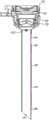
图6描绘了沿图4的线6-6截取的图4的插管组件的横剖视图;6 depicts a cross-sectional view of the cannula assembly of FIG. 4 taken along line 6-6 of FIG. 4;
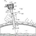
图7A描绘了定位在患者的腹壁内的图4的插管组件的剖视图,其中临床医生正手持插管组件,其中插管组件与目标区域适当地对准;7A depicts a cross-sectional view of the cannula assembly of FIG. 4 positioned within the abdominal wall of a patient, wherein a clinician is holding the cannula assembly with the cannula assembly properly aligned with the target area;
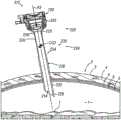
图7B描绘了定位在患者的腹壁内的图4的插管组件的剖视图,其中临床医生已释放插管组件,使得插管组件已倾斜并且不再与图7A的目标区域对准;7B depicts a cross-sectional view of the cannula assembly of FIG. 4 positioned within the patient's abdominal wall, wherein the clinician has released the cannula assembly such that the cannula assembly has tilted and is no longer aligned with the target area of FIG. 7A;
图8描绘了示例性插管的透视图;Figure 8 depicts a perspective view of an exemplary cannula;
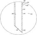
图9描绘了沿图8的线9-9截取的图8的插管的横剖面图;Figure 9 depicts a cross-sectional view of the cannula of Figure 8 taken along line 9-9 of Figure 8;
图10描绘了图8的插管的近侧部分的放大横剖视图;Figure 10 depicts an enlarged cross-sectional view of a proximal portion of the cannula of Figure 8;
图11描绘了图8的插管的远侧部分的放大横剖视图;Figure 11 depicts an enlarged cross-sectional view of the distal portion of the cannula of Figure 8;
图12A描绘了由图8的插管和图5的一次性密封组件形成的插管组件的剖视图,其中插管组件定位在患者的腹壁内,其中临床医生正手持插管组件,其中插管组件与目标区域适当地对准;12A depicts a cross-sectional view of a cannula assembly formed from the cannula of FIG. 8 and the disposable seal assembly of FIG. Properly aligned with the target area;
图12B描绘了定位在图12A的腹壁内的图12A的插管组件的剖视图,其中插管组件已被临床医生释放并且保持与目标区域适当地对准;并且12B depicts a cross-sectional view of the cannula assembly of FIG. 12A positioned within the abdominal wall of FIG. 12A , wherein the cannula assembly has been released by the clinician and remains properly aligned with the target area; and
图13描绘了示例性插管的横剖视图。13 depicts a cross-sectional view of an exemplary cannula.
附图并非旨在以任何方式进行限制,并且可以设想本发明的各种实施方案可以多种其它方式来执行,包括那些未必在附图中示出的方式。并入本说明书中并构成其一部分的附图示出了本发明的若干方面,并与说明书一起用于解释本发明的原理;然而,应当理解,本发明并不限于所示出的明确布置方式。The drawings are not intended to be limiting in any way, and it is contemplated that various embodiments of the invention may be carried out in numerous other ways, including those not necessarily shown in the drawings. The accompanying drawings, which are incorporated in and constitute a part of this specification, illustrate several aspects of the invention and together with the description serve to explain the principles of the invention; it is to be understood, however, that the invention is not limited to the precise arrangements shown. .
具体实施方式Detailed ways
本发明的某些示例的以下说明不应用于限定本发明的范围。根据以举例的方式示出的以下说明,本发明的其他示例、特征、方面、实施方案和优点对于本领域的技术人员而言将是显而易见的,一种最佳方式被设想用于实施本发明。如将认识到,本发明能够具有其它不同且明显的方面,所有这些方面均不脱离本发明。因此,附图和说明应被视为实质上是例示性的而非限制性的。The following description of certain examples of the invention should not be used to limit the scope of the invention. Other examples, features, aspects, embodiments and advantages of the invention will be apparent to those skilled in the art from the following description, shown by way of example, and one of the best modes contemplated for carrying out the invention . As will be realized, the invention is capable of other different and obvious aspects, all without departing from the invention. Accordingly, the drawings and descriptions are to be regarded as illustrative in nature and not restrictive.
为清楚公开内容起见,术语“近侧”和“远侧”在本文中相对于抓握外科装置的外科医生或其他操作者而定义。术语“近侧”是指元件的更靠近外科医生布置的位置,并且术语“远侧”是指元件的进一步远离外科医生的位置。此外,在本文中参照附图来使用空间术语诸如“顶部”、“底部”、“上部”、“下部”、“竖直”、“水平”等的程度上来说,应当理解,此类术语仅用于示例性描述目的,并且不旨在是限制性的或绝对的。就这一点而言,应当理解,外科器械诸如本文所公开的那些可以不限于本文所示和所述的那些取向和位置的多种取向和位置使用。For clarity of disclosure, the terms "proximal" and "distal" are defined herein with respect to a surgeon or other operator grasping a surgical device. The term "proximal" refers to a location of an element closer to a surgeon's placement, and the term "distal" refers to a location of an element further away from the surgeon. Further, to the extent that spatial terms such as "top", "bottom", "upper", "lower", "vertical", "horizontal", etc. are used herein with reference to the drawings, it should be understood that such terms only It is used for exemplary descriptive purposes and is not intended to be limiting or absolute. In this regard, it should be understood that surgical instruments such as those disclosed herein can be used in a variety of orientations and positions not limited to those shown and described herein.
此外,如本文所用的与任何数值或范围相关的术语“约”和“大约”旨在涵盖所引用的确切值,以及使得所引用的特征部或特征部的组合能够用于本文所述的预期目的的合适公差。Furthermore, the terms "about" and "approximately" as used herein in relation to any numerical value or range are intended to encompass the exact value recited, as well as to enable the recited feature or combination of features to be used for the contemplated values described herein. An appropriate tolerance for the purpose.
I.示例性的单次使用的套管针和可重复使用的套管针I. Exemplary Single Use Trocars and Reusable Trocars
图1至图5示出了呈单次使用的第一套管针(10)和可重复使用的第二套管针(110)形式的示例性外科介入装置,每个套管针被构造成能够在腹腔镜式外科手术中提供外科部位通路。每个套管针(10,110)包括具有工作通道(14,114)的插管组件(12,112)和被构造成能够可移除地同轴地插入工作通道(14,114)中的闭塞器(16,116),使得组装好的套管针(10,110)可被朝远侧引导穿过患者的腹壁并接近腹腔,例如如下文结合图3A至图3D所述。1-5 illustrate an exemplary surgical intervention device in the form of a single-use first trocar (10) and a reusable second trocar (110), each configured to Capable of providing surgical site access during laparoscopic surgery. Each trocar (10, 110) includes a cannula assembly (12, 112) having a working channel (14, 114) and an obturator (16, 116) configured to be removably coaxially inserted into the working channel (14, 114) such that assembled A good trocar (10, 110) may be directed distally through the patient's abdominal wall and into access to the abdominal cavity, for example as described below in connection with Figures 3A-3D.
A.示例性的单次使用的套管针A. Exemplary single-use trocar
如图1至图2所示,单次使用的套管针(10)的插管组件(12)包括插管(20)和密封壳体(30)。插管(20)和密封壳体(30)配合以限定工作通道(14),该工作通道沿着套管针(10)的中心轴线(A)纵向延伸。具体地,工作通道(14)由与密封壳体(30)的中空内部连通的插管(20)的内腔限定。插管组件(12)被构造成能够穿过工作通道(14)在远侧接收细长外科器械,以提供接近患者腹腔内的外科部位的通路。如下文更详细地描述,密封壳体(30)容纳一对密封结构,该对密封结构限定密封组件,该密封组件被构造成能够保持对患者腹腔的吹入,同时允许外科器械和组织碎片沿着工作通道(14)通过。As shown in FIGS. 1-2 , the cannula assembly ( 12 ) of the single-use trocar ( 10 ) includes a cannula ( 20 ) and a sealed housing ( 30 ). Cannula (20) and seal housing (30) cooperate to define a working channel (14) extending longitudinally along a central axis (A) of trocar (10). Specifically, the working channel (14) is defined by the lumen of the cannula (20) communicating with the hollow interior of the sealed housing (30). The cannula assembly (12) is configured to receive an elongated surgical instrument distally through the working channel (14) to provide access to a surgical site within the patient's abdominal cavity. As described in more detail below, the seal housing (30) houses a pair of seal structures that define a seal assembly configured to maintain insufflation of the patient's abdominal cavity while allowing surgical instruments and tissue fragments to pass along the Pass along the working channel (14).
本型式的插管(20)可包括:钟形毂(未示出),该钟形毂位于插管的近侧端部处;和细长圆柱形管(22),该细长圆柱形管从毂朝远侧延伸并终止于成角度的插管尖端(24)处。插管管部(22)的外表面包括呈环形肋(26)形式的多个组织抓持特征部,这些环形肋沿着插管管部(22)的中间部分轴向布置。肋(26)被构造成能够抓持插管(20)插入穿过的腹壁组织层,并由此有助于在插管(20)定位在形成于患者腹壁中的开口内时沿轴向方向和径向方向稳定插管(20)。Cannula (20) of this version may include: a bell-shaped hub (not shown) located at the proximal end of the cannula; and an elongated cylindrical tube (22) that Extends distally from the hub and terminates at an angled cannula tip (24). The outer surface of cannula tube (22) includes a plurality of tissue-grasping features in the form of annular ribs (26) arranged axially along the middle portion of cannula tube (22). Ribs (26) are configured to grip the layers of abdominal wall tissue through which cannula (20) is inserted, and thereby facilitate axial direction when cannula (20) is positioned within an opening formed in the patient's abdominal wall. and radial direction stabilizing cannula (20).
更具体地,本示例的组织抓持肋(26)在插管管部(22)的侧壁中形成为环形扇形,使得每个肋(26)从肋(26)的径向最外边缘沿远侧方向径向向内渐缩。因此,肋26的径向最外边缘与插管管部(22)的无肋近侧部分和远侧部分大致齐平。所产生的肋(26)的构型促进插管管部(22)沿远侧方向穿过组织层的前进,并阻止插管管部(22)沿相反的近侧方向穿过组织层的缩回。有利地,这种构型防止插管管部(22)在外科手术期间从患者腹壁的意外抽出。然而,应当理解,在套管针(10)的其他型式中,插管管部(22)可设置有各种其他类型的组织抓持特征部。例如,插管管部(22)可包括呈一个或多个螺旋肋的形式的组织抓持特征部,该一个或多个螺旋肋围绕插管管部(22)的至少中间部分延伸,并且可类似于肋(26)呈扇形。More specifically, the tissue-grasping ribs (26) of the present example are formed in the sidewall of the cannula tube (22) as an annular sector such that each rib (26) runs from the radially outermost edge of the rib (26) along the The distal direction tapers radially inwardly. Accordingly, the radially outermost edges of
插管组件(12)的密封壳体(30)包括近侧壳体部分(32)和远侧壳体部分(34),近侧壳体部分(32)可移除地附接到该远侧壳体部分。近侧壳体部分(32)包括固定在一起的近侧头部(36)和远侧基部(38)。远侧壳体部分(34)包括:远侧护罩(40),该远侧护罩环绕插管(20)的近侧毂(未示出);盖板(42),该盖板固定到远侧护罩(40)的近侧端部;和闩锁环(44),该闩锁环可旋转地设置在远侧护罩和盖板之间并具有径向向外突出的突片(46)。闩锁环(44)可经由突片(46)围绕套管针(10)的中心轴线(A)在锁定位置和解锁位置之间选择性地旋转。在锁定位置,闩锁环(44)将近侧壳体部分(32)锁定到远侧壳体部分(34)。在解锁位置,闩锁环(44)允许近侧壳体部分(32)与远侧壳体部分(34)分开,例如以直接接近容纳在远侧壳体部分(34)内的远侧密封结构(未示出)。在一些型式中,远侧护罩(40)可与插管管部(22)的近侧端部一体形成,使得远侧护罩(40)是插管(20)的部件。The sealed housing (30) of the cannula assembly (12) includes a proximal housing portion (32) and a distal housing portion (34) to which the proximal housing portion (32) is removably attached. shell part. The proximal housing portion (32) includes a proximal head (36) and a distal base (38) secured together. The distal housing portion (34) includes: a distal shield (40), which surrounds a proximal hub (not shown) of the cannula (20); a cover plate (42), which is secured to the proximal end of the distal shield (40); and a latch ring (44) rotatably disposed between the distal shield and the cover plate and having radially outwardly projecting tabs ( 46). Latch ring (44) is selectively rotatable about a central axis (A) of trocar (10) between a locked position and an unlocked position via tabs (46). In the locked position, the latch ring (44) locks the proximal housing portion (32) to the distal housing portion (34). In the unlocked position, the latch ring (44) allows the proximal housing portion (32) to be separated from the distal housing portion (34), for example to provide direct access to the distal sealing structure housed within the distal housing portion (34). (not shown). In some versions, distal shield (40) may be integrally formed with the proximal end of cannula barrel (22), such that distal shield (40) is a component of cannula (20).
尽管未示出,但近侧壳体部分(32)容纳近侧(或“外”)密封结构,并且远侧壳体部分(34)容纳远侧(或“内”)密封结构,两者均沿着套管针(10)的中心轴线(A)布置。近侧密封结构和远侧密封结构配合以限定密封组件,该密封组件保持在外科手术期间对患者腹腔的吹入,同时允许外科器械和组织碎片沿着工作通道(14)通过。例如,近侧密封结构可包括环形密封构件,该环形密封构件被构造成能够密封地接合被引导穿过工作通道(14)的腹腔镜式外科器械的轴。远侧端部密封结构可包括鸭嘴形密封构件,该鸭嘴形密封构件被构造成能够在没有外科器械轴的情况下将工作通道(14)保持在密封状态。Although not shown, proximal housing portion (32) houses a proximal (or “outer”) seal and distal housing portion (34) houses a distal (or “inner”) seal, both Arranged along the central axis (A) of the trocar (10). The proximal and distal seal structures cooperate to define a seal assembly that maintains insufflation of the patient's abdominal cavity during a surgical procedure while allowing passage of surgical instruments and tissue debris along the working channel (14). For example, the proximal sealing structure may include an annular sealing member configured to sealingly engage a shaft of a laparoscopic surgical instrument guided through the working channel (14). The distal end sealing structure may include a duckbill-shaped sealing member configured to maintain the working channel (14) in a sealed state in the absence of a surgical instrument shaft.
插管组件(12)还包括吹入端口(50),该吹入端口与插管(20)的近侧端部可操作地联接并具有呈旋塞阀(52)形式的可调节阀。吹入端口(50)被构造成能够将来自流体源(未示出)的诸如二氧化碳的吹入流体朝远侧引导穿过工作通道(14)并接近患者的腹腔,由此使用流体对该腔体进行扩展(或“吹入”)。腹腔的这种扩展为更容易执行腹腔镜式外科手术创造了额外的空间。Cannula assembly (12) also includes an insufflation port (50) operably coupled to the proximal end of cannula (20) and having an adjustable valve in the form of a stopcock (52). Insufflation port (50) is configured to direct an insufflation fluid, such as carbon dioxide, from a fluid source (not shown) distally through working channel (14) and proximally to the patient's abdominal cavity, thereby injecting the fluid into the cavity. The body is expanded (or "blown"). This expansion of the abdominal cavity creates additional space to more easily perform laparoscopic surgery.
如图1和图2所示,套管针(10)的闭塞器(16)包括近侧头部(60)、从头部(60)朝远侧延伸的细长圆柱形轴(62)和锥形远侧尖端(64)。闭塞器轴(62)被构造成能够被接纳在插管组件(12)的工作通道(14)内,使得闭塞器尖端(64)延伸穿过插管尖端(24)并朝远侧延伸。闭塞器头部(60)包括穹顶形上部主体(66)、基板(68)和可致动的闩锁构件(70),该闩锁构件包括一对闩锁臂(72)和对应的一对闩锁按钮(74)。闩锁臂(72)被构造成能够被捕获在形成于密封壳体头部(36)的顶表面中的相应狭槽(未示出)内,以将闭塞器(16)与插管组件(12)联接。闩锁按钮(74)是可致动的,以从狭槽中释放闭锁臂(72),并由此允许闭塞器(16)与插管组件(12)分开。闭塞器(16)还包括纵向延伸穿过闭塞器头部(60)和闭塞器轴(62)的中心通道(76),并且被构造成能够在其中接纳内窥镜(未示出)以在穿过患者腹壁插入套管针(10)期间提供可视化。闭塞器头部(60)的夹持杆(78)可枢转以将内窥镜选择性地固定在中心通道(76)内。中心通道(76)和夹持杆(78)仅仅是可选特征部,并且在其他型式中可从闭塞器(16)中省略。As shown in Figures 1 and 2, the obturator (16) of the trocar (10) includes a proximal head (60), an elongated cylindrical shaft (62) extending distally from the head (60) and Tapered distal tip (64). Obturator shaft (62) is configured to be received within working channel (14) of cannula assembly (12) such that obturator tip (64) extends through cannula tip (24) and distally. The obturator head (60) includes a dome-shaped upper body (66), a base plate (68) and an actuatable latch member (70) comprising a pair of latch arms (72) and a corresponding pair of Latch button (74). The latch arms (72) are configured to be captured within corresponding slots (not shown) formed in the top surface of the seal housing head (36) to secure the obturator (16) to the cannula assembly ( 12) Connection. Latch button (74) is actuatable to release latch arm (72) from slot and thereby allow obturator (16) to be separated from cannula assembly (12). The obturator (16) also includes a central channel (76) extending longitudinally through the obturator head (60) and obturator shaft (62) and configured to receive an endoscope (not shown) therein for Visualization is provided during insertion of the trocar (10) through the patient's abdominal wall. The clamping lever (78) of the obturator head (60) is pivotable to selectively secure the endoscope within the central channel (76). Central channel (76) and clamping rod (78) are optional features only and may be omitted from obturator (16) in other versions.
插管组件(12)和闭塞器(16)可被构造成能够在患者单次使用之后被丢弃。在其他型式中,套管针(10)的一个或多个部件可被适当地构造成能够承受消毒和多次重复使用,例如如下文结合图4至图5的套管针(110)更详细地描述的。Cannula assembly (12) and obturator (16) may be configured to be disposable after a single use by the patient. In other versions, one or more components of the trocar (10) may be suitably configured to withstand sterilization and multiple re-uses, such as trocar (110) as described in more detail below in connection with FIGS. 4-5. described.
B.套管针接近患者腹腔的示例性部署B. Exemplary Deployment of a Trocar Approximate to a Patient's Abdominal Cavity
图3A至图3D示出了使用上述套管针(10)穿过患者腹壁(2)接近患者腹腔(1)的示例性方法。应当理解,腹壁(2)包括向外的浅层和向内的深层。浅层通常包括皮肤(3)的外层和脂肪(4)的内层;而较深的层包括肌肉(5)和筋膜(6)的交替层,这些层是纤维性且柔性的,具有比浅层相对更高的拉伸强度。Figures 3A-3D illustrate an exemplary method of accessing a patient's abdominal cavity (1 ) through the patient's abdominal wall (2) using the trocar (10) described above. It should be understood that the abdominal wall (2) comprises a superficial layer facing outwards and a deep layer facing inwards. The superficial layer usually consists of an outer layer of skin (3) and an inner layer of fat (4); while the deeper layer consists of alternating layers of muscle (5) and fascia (6), which are fibrous and flexible, with Relatively higher tensile strength than shallow layers.
如图3A所示,在闭塞器(16)被接纳在插管组件(12)内并连接到密封壳体(30)的情况下,临床医生经由闭塞器头部(60)和密封壳体(30)操纵套管针(10)以推动闭塞器尖端(64)抵靠皮肤(3)并在来回旋转套管针(10)的同时向内朝向腹腔(1)。套管针(10)的继续向内推动进一步引导闭塞器尖端(64)和插管尖端(24)朝远侧穿过脂肪(4)和筋膜(5)的层并接近腔体(1),如图3B所示。如上文所讨论,通过由安装在闭塞器(16)内的内窥镜(未示出)提供的可视化,可促进此步骤。一旦插管(20)已到达插入腔体(1)中的期望深度,临床医生经由按压闩锁按钮(74)从密封壳体(30)释放闭塞器头部(60),然后从插管组件(12)从近侧抽出闭塞器(16),如图3C所示。这使得插管组件(12)的工作通道(14)能够自由地接纳朝远侧穿过其的外科器械,以便执行腹腔镜式外科手术。如上所述,设置在插管管部(22)上的组织接合肋(26)抓持腹壁(2)的组织层(3,4,5),从而使插管组件(12)相对于腹壁(2)具有至少最小程度的稳定性。在完成腹腔镜式外科手术后,临床医生抓握密封壳体(30)并从腹壁(2)朝近侧抽出插管组件(12),如图3D所示。As shown in Figure 3A, with the obturator (16) received within the cannula assembly (12) and connected to the seal housing (30), the clinician passes through the obturator head (60) and the seal housing ( 30) Manipulate the trocar (10) to push the obturator tip (64) against the skin (3) and inwardly towards the abdominal cavity (1 ) while rotating the trocar (10) back and forth. Continued inward advancement of the trocar (10) further guides the obturator tip (64) and cannula tip (24) distally through the layers of fat (4) and fascia (5) and towards the lumen (1) , as shown in Figure 3B. As discussed above, this step is facilitated by visualization provided by an endoscope (not shown) mounted within obturator (16). Once the cannula (20) has reached the desired depth of insertion into the lumen (1), the clinician releases the obturator head (60) from the sealed housing (30) by pressing the latch button (74), and then removes the cannula assembly (12) Withdraw the obturator (16) proximally, as shown in Figure 3C. This allows the working channel (14) of cannula assembly (12) to freely receive surgical instruments passing therethrough distally for performing laparoscopic surgery. As mentioned above, the tissue engaging ribs (26) provided on the cannula tube (22) grip the tissue layers (3, 4, 5) of the abdominal wall (2), thereby positioning the cannula assembly (12) relative to the abdominal wall ( 2) Has at least a minimal degree of stability. After completing the laparoscopic surgical procedure, the clinician grasps the sealed housing (30) and withdraws the cannula assembly (12) proximally from the abdominal wall (2), as shown in Figure 3D.
C.具有一次性密封组件的示例性的可重复使用的套管针C. Exemplary reusable trocar with disposable seal assembly
在一些情况下,可能期望将套管针构造成使得其一个或多个部件可被消毒并重新用于多个外科规程,而一个或多个其他部件可在每个规程之后被容易且经济地处置和更换。图4至图5示出了以这种方式构造的另一示例性套管针(110),该套管针的结构和功能类似于上述套管针(10),除非下文另有描述。In some cases, it may be desirable to configure the trocar such that one or more components thereof can be sterilized and reused for multiple surgical procedures, while one or more other components can be easily and economically disposed of after each procedure. Disposal and replacement. Figures 4-5 illustrate another exemplary trocar (110) configured in this manner, which is similar in structure and function to the trocar (10) described above unless otherwise described below.
与套管针(10)类似,套管针(110)包括具有工作通道(114)的插管组件(112)和被构造成能够沿着工作通道(114)同轴地插入插管组件(112)中的闭塞器(116)。插管组件(112)包括插管(120),该插管具有:钟形毂(122),该钟形毂位于插管的近侧端部处;和细长圆柱形管(124),该细长圆柱形管从毂(122)朝远侧延伸并终止于成角度的插管尖端(126)处。插管管部(124)的外表面包括呈环形肋(128)形式的多个组织抓持特征部,这些环形肋沿着插管管部(124)的中间部分轴向布置并且类似于上述肋(26)。Similar to the trocar (10), the trocar (110) includes a cannula assembly (112) having a working channel (114) and a cannula assembly (112) configured to be coaxially inserted along the working channel (114). ) in the obturator (116). Cannula assembly (112) includes cannula (120), and this cannula has: bell-shaped hub (122), and this bell-shaped hub is positioned at the proximal end place of cannula; An elongated cylindrical tube extends distally from hub (122) and terminates at angled cannula tip (126). The outer surface of cannula tube (124) includes a plurality of tissue-grasping features in the form of annular ribs (128) arranged axially along the middle portion of cannula tube (124) and similar to the ribs described above. (26).
插管组件(112)还包括密封组件(130)。与由套管针(10)的密封壳体(30)限定的密封组件不同,密封组件(130)被构造为模块化的可替换单元,其被构造成能够与插管(120)的近侧毂(122)可释放地配合。如图5中最佳示出,本示例的密封组件(130)通常包括以同轴布置相对于彼此固定的上部框架构件(132)、中间框架构件(134)和下部框架构件(136)。尽管未示出,但近侧(或“外”)密封结构被支撑在上部框架构件(132)内,而远侧(或“内部”)密封结构被支撑在下部框架构件(136)内。此类密封结构在结构和功能上可类似于上述套管针(10)的近侧密封结构和远侧密封结构。密封组件(130)还包括吹入端口(140),该吹入端口具有呈旋塞阀(142)形式的可调节阀。Cannula assembly (112) also includes a seal assembly (130). Unlike the seal assembly defined by seal housing (30) of trocar (10), seal assembly (130) is configured as a modular, replaceable unit configured to attach to the proximal end of cannula (120). Hub (122) is releasably engaged. As best shown in FIG. 5 , the seal assembly ( 130 ) of the present example generally includes an upper frame member ( 132 ), a middle frame member ( 134 ), and a lower frame member ( 136 ) fixed relative to each other in a coaxial arrangement. Although not shown, the proximal (or "outer") sealing structure is supported within upper frame member (132) and the distal (or "inner") sealing structure is supported within lower frame member (136). Such seals may be similar in structure and function to the proximal and distal seals of the trocar (10) described above. The seal assembly (130) also includes an insufflation port (140) having an adjustable valve in the form of a stopcock (142).
密封组件(130)的在吹入端口(140)远侧的下部部分被构造成能够安置在插管(120)的近侧毂(122)内,使得围绕下部部分沿周向设置的环形密封构件(144)密封地接合插管毂(122)的内表面。以此方式,密封组件(130)的内部与插管(120)的内腔流体连通以限定插管组件(112)的工作通道(114),可以上文结合套管针(10)大致描述的方式引导吹入流体、外科器械和组织碎片穿过该工作通道。密封组件(130)可根据以下专利的一个或多个教导内容进行进一步构造:2019年3月28日公布的名称为“Trocar Seal Assemblies”的美国专利公布2019/0090905,其公开内容以引用方式并入本文;和/或2019年12月19日公布的名称为“Asymmetric Shaft Seal”的美国专利公布2019/0380742,其公开内容以引用方式并入本文。A lower portion of seal assembly (130) distal to insufflation port (140) is configured to be seated within proximal hub (122) of cannula (120) such that an annular seal member circumferentially disposed around the lower portion (144) sealingly engages the inner surface of cannula hub (122). In this manner, the interior of seal assembly (130) is in fluid communication with the lumen of cannula (120) to define working channel (114) of cannula assembly (112), as generally described above in connection with trocar (10). The working channel guides insufflation fluid, surgical instruments, and tissue fragments through the working channel. The seal assembly (130) may be further constructed in accordance with the teachings of one or more of the following patents: U.S. Patent Publication 2019/0090905, entitled "Trocar Seal Assemblies," published March 28, 2019, the disclosure of which is incorporated by reference and/or U.S. Patent Publication 2019/0380742, entitled "Asymmetric Shaft Seal," published December 19, 2019, the disclosure of which is incorporated herein by reference.
如图5中最佳示出,套管针(110)的闭塞器(116)包括近侧头部(150)、从头部(150)朝远侧延伸的细长圆柱形轴(152)和位于轴(152)的远侧端部处的锥形尖端(154)。闭塞器头部(150)包括穹顶形上部主体(156)、基板(158)和可致动的闩锁构件(160),该闩锁构件包括一对向下延伸的闩锁臂(162)和对应的一对闩锁按钮(164)。闩锁臂(162)被构造成能够被捕获在形成于密封组件(130)的上部框架构件(132)的顶表面中的相应狭槽(138)内,以将闭塞器(116)与插管组件(112)联接。闩锁按钮(164)是可致动的,以从狭槽(138)中释放闭锁臂(162),并由此允许闭塞器(116)与插管组件(112)分开。As best shown in FIG. 5 , obturator ( 116 ) of trocar ( 110 ) includes a proximal head ( 150 ), an elongated cylindrical shaft ( 152 ) extending distally from head ( 150 ), and Tapered tip (154) at the distal end of shaft (152). The obturator head (150) includes a dome-shaped upper body (156), a base plate (158) and an actuatable latch member (160) comprising a pair of downwardly extending latch arms (162) and A corresponding pair of latch buttons (164). The latch arms (162) are configured to be captured within corresponding slots (138) formed in the top surface of the upper frame member (132) of the seal assembly (130) to secure the obturator (116) to the cannula. Components (112) are coupled. Latch button (164) is actuatable to release latch arm (162) from slot (138) and thereby allow obturator (116) to separate from cannula assembly (112).
本示例的插管(120)和闭塞器(116)适当地由坚固的材料(诸如外科钢)构成,使得它们可被消毒并重新用于多个外科规程。相比之下,如上所述,密封组件(130)被构造为一次性单元,旨在与插管(120)分开并在每个规程后更换。例如,密封组件(130)可由包括塑料和橡胶的各种聚合物材料构成,使得密封组件(130)可容易地制造并以使得密封组件(130)适合在单次使用后处置的价格出售,类似于上述套管针(10)。Cannula (120) and obturator (116) of the present example are suitably constructed of a strong material, such as surgical steel, so that they can be sterilized and reused for multiple surgical procedures. In contrast, as described above, sealing assembly (130) is configured as a disposable unit, intended to be separated from cannula (120) and replaced after each procedure. For example, seal assembly (130) can be constructed of various polymeric materials including plastics and rubber, such that seal assembly (130) can be easily manufactured and sold at a price that makes seal assembly (130) suitable for disposal after a single use, like on the above trocar (10).
II.用于可重复使用的套管针的示例性平衡特征部II. Exemplary Balancing Features for Reusable Trocars
如图6最佳所示,插管组件(112)的重心(CG1)位于细长圆柱形管部(124)的近侧端部和钟形毂(122)附近。另外,细长圆柱形管部(124)的横截面厚度在细长圆柱形管部(124)的近侧端部和远侧端部处可以是基本上均匀的,其中横截面厚度略有偏差以适应环形肋(128)。换句话讲,圆柱形管部(124)的近侧部分和远侧部分的内径和外径可以基本上相同。As best shown in FIG. 6, the center of gravity (CG1) of cannula assembly (112) is located near the proximal end of elongated cylindrical tube (124) and bell-shaped hub (122). Additionally, the cross-sectional thickness of the elongated cylindrical tube (124) may be substantially uniform at the proximal and distal ends of the elongated cylindrical tube (124), with slight deviations in the cross-sectional thickness to accommodate the annular rib (128). In other words, the inner and outer diameters of the proximal and distal portions of the cylindrical tube (124) may be substantially the same.
由于插管(120)和闭塞器(116)由坚固的材料构造,插管(120)和闭塞器(116)可具有与上述单次使用的套管针(10)的插管(12)和闭塞器(16)相比更大的质量和所得重量。如下文将更详细地描述的,插管(120)的更大的质量和重量可以在横向(即径向或侧向)方向上引起插管(120)相对于腹壁(2)的不稳定性和/或缺乏平衡,使得插管(120)可以在根据本文的描述的示例性使用期间指向或倾斜到一侧,因此导致工作通道(114)变得与目标操作区域(T)不对准。Since cannula (120) and obturator (116) are constructed of strong materials, cannula (120) and obturator (116) can have the cannula (12) and The obturator (16) has a comparatively greater mass and resulting weight. As will be described in more detail below, the greater mass and weight of cannula (120) can cause instability of cannula (120) relative to abdominal wall (2) in the transverse (i.e. radial or lateral) direction And/or a lack of balance such that cannula (120) can point or tilt to one side during exemplary use according to the description herein, thus causing working channel (114) to become misaligned with target operating region (T).
图7A示出了根据本文的教导内容,插管组件(112)经由工作通道(114)提供接近患者体腔(1)的合适通道。因此,在接近图7A所示的位置之前,闭塞器(116)和插管组件(112)可彼此结合使用,使得闭塞器尖端(154)和插管尖端(126)被朝远侧推动穿过皮肤(3)、脂肪层(4)和筋膜层(5)以便接近体腔(1)。一旦提供了接近,临床医生就可根据本文的描述移除闭塞器(116)。接下来,如图7A所示,临床医生可以将插管组件(112)相对于患者放置在期望位置,使得中心轴线(A1)与目标操作区域(T)对准。类似于上述组织接合肋(26),设置在插管管部(124)上的组织接合肋(128)抓持腹壁(2)的组织层(3,4,5),从而使插管组件(112)相对于腹壁(2)具有至少最小程度的轴向方向和横向方向稳定性。Figure 7A illustrates cannula assembly (112) providing suitable access to patient body lumen (1) via working channel (114) in accordance with the teachings herein. Accordingly, prior to approaching the position shown in FIG. 7A , obturator ( 116 ) and cannula assembly ( 112 ) may be used in conjunction with each other such that obturator tip ( 154 ) and cannula tip ( 126 ) are pushed distally through the The skin (3), fat layer (4) and fascia layer (5) for access to the body cavity (1). Once access is provided, the clinician can remove the obturator (116) as described herein. Next, as shown in FIG. 7A , the clinician may place cannula assembly ( 112 ) in a desired position relative to the patient such that central axis ( Al ) is aligned with the target operating region ( T ). Similar to the tissue engaging ribs (26) described above, the tissue engaging ribs (128) disposed on the cannula tube (124) grip the tissue layers (3,4,5) of the abdominal wall (2), thereby allowing the cannula assembly ( 112) Having at least a minimal degree of stability in the axial direction and in the transverse direction relative to the abdominal wall (2).
在示例性使用期间,可能期望中心轴线(A1)在临床医生释放插管组件(112)之后维持与目标操作区域(T)的正确对准,以便根据本文的描述经由工作通道(114)接近体腔(1)。然而,在一些情况下,如图7A至图7B之间所示,当临床医生释放插管组件(112)时,插管组件(112)可能变得不平衡并且“翻倒”,使得工作通道(114)变得与目标操作区域(T)不对准。During exemplary use, it may be desirable for the central axis (A1) to maintain proper alignment with the target operating region (T) after the clinician releases the cannula assembly (112) in order to access the body lumen via the working channel (114) as described herein (1). However, in some cases, as shown between FIGS. 7A-7B , when the clinician releases cannula assembly (112), cannula assembly (112) may become unbalanced and "tip over," allowing the working channel to (114) Becomes out of alignment with the target operating region (T).
在重心(CG1)与组织接合肋(128)的接合腹壁(2)的部分侧向间隔开的情况下,可产生支点力和所得扭矩。由插管组件(112)的重量产生并且作用在重心(CG1)处的支点力作为扭矩施加在肋(128)的接合腹壁(2)的部分上,并且可能变得过大,使得插管组件(112)翻倒,从而使工作通道(114)与目标操作区域(T)不对准。与上述插管组件(12)相比,插管组件(112)可能更容易翻倒,部分地由于插管组件(112)的增加的重量,该增加的重量继而产生作用在重心处的更大的支点力,因此产生围绕插管组件(112)的定位在腹壁(2)内的部分的更大的翻倒扭矩。因此,对于重量轻、单次使用的插管(20)而言可接受的重心位置,对于由坚固的材料形成以促进消毒和在多个外科手术中重复使用的较重插管(120)而言可能是不可接受的。With the center of gravity (CG1 ) spaced laterally from the portion of the tissue engaging rib (128) that engages the abdominal wall (2), a fulcrum force and resulting torque can be generated. The fulcrum force generated by the weight of the cannula assembly (112) and acting at the center of gravity (CG1) acts as a torque on the portion of the rib (128) that engages the abdominal wall (2) and can become excessive, causing the cannula assembly to (112) overturns, thereby misaligning the working channel (114) with the target operating area (T). Cannula assembly (112) may tip over more easily than cannula assembly (12) described above, due in part to the increased weight of cannula assembly (112), which in turn creates a greater fulcrum force, thus creating a greater tipping torque around the portion of cannula assembly (112) positioned within abdominal wall (2). Thus, an acceptable center of gravity position for a lightweight, single-use cannula (20) is less desirable for a heavier cannula (120) formed of a strong material to facilitate sterilization and reuse in multiple surgical procedures. Words may be unacceptable.
如上所述,插管组件(112)可能变得不平衡并且“翻倒”,使得工作通道(114)变得不期望地与目标操作区域(T)不对准。因此,可能期望插管组件(112)具有平衡特征部,该平衡特征部可帮助促进插管组件(112)相对于腹壁(2)的期望放置,使得(A)工作通道(114)可以在根据本文的描述的示例性使用期间保持与目标操作区域(T)适当地对准,并且(B)插管(120)可以由坚固的材料形成以用于消毒和重复使用的目的。As noted above, cannula assembly (112) may become unbalanced and "tip over," such that working channel (114) becomes undesirably misaligned with target operating region (T). Accordingly, it may be desirable for cannula assembly (112) to have a balance feature that can help facilitate the desired placement of cannula assembly (112) relative to abdominal wall (2) such that (A) working channel (114) can Proper alignment with the target procedure area (T) is maintained during exemplary use described herein, and (B) cannula (120) may be formed of a strong material for sterilization and re-use purposes.
图8至图11示出了可用于替换上述插管(120)的示例性插管(220);而图12A至图12B示出了由插管(220)和密封壳体(130)形成的插管组件(212)的示例性使用。插管(220)包括:钟形毂(222),该钟形毂位于插管的近侧端部处;和细长圆柱形管部(224),该细长圆柱形管部从毂(222)朝远侧延伸并终止于成角度的插管尖端(226)处;以上所有限定工作通道(214)。插管管部(224)的外表面包括呈环形肋(228)形式的多个组织抓持特征部,这些环形肋沿插管管部(224)的中间部分轴向布置。钟形毂(222)、细长圆柱形管部(224)、成角度的插管尖端(226)、工作通道(214)和环形肋(228)可基本上类似于钟形毂(122)、细长圆柱形管部(124)、成角度的插管尖端(126)、工作通道(114)和环形肋(128),其中差异在下文详述。Figures 8 to 11 show an exemplary cannula (220) that can be used to replace the cannula (120) described above; Exemplary Use of Cannula Assembly (212). Cannula (220) includes: a bell-shaped hub (222) located at the proximal end of the cannula; and an elongated cylindrical tube (224) extending from hub (222) ) extend distally and terminate at an angled cannula tip (226); all of the above define the working channel (214). The outer surface of cannula tube (224) includes a plurality of tissue-grasping features in the form of annular ribs (228) disposed axially along a medial portion of cannula tube (224). Bell-shaped hub (222), elongated cylindrical tube (224), angled cannula tip (226), working channel (214), and annular rib (228) may be substantially similar to bell-shaped hub (122), Elongated cylindrical tube (124), angled cannula tip (126), working channel (114) and annular rib (128), with the differences detailed below.
插管(220)还包括集成到插管管部(224)中的平衡特征部(235)。如下文将更详细地描述的,平衡特征部(235)被构造成能够在临床医生释放插管组件(212)时阻止插管组件(212)翻倒,使得工作通道(214)可保持与目标操作区域(T)对准。Cannula (220) also includes a balance feature (235) integrated into cannula barrel (224). As will be described in more detail below, balance feature (235) is configured to prevent cannula assembly (212) from tipping over when the clinician releases cannula assembly (212), so that working channel (214) can remain aligned with the target. Operating area (T) alignment.
平衡特征部(235)包括具有相对较薄的壁厚的近侧较薄区段(230)、具有相对较厚的壁厚的远侧较厚区段(232)以及在近侧区段与远侧区段(230,232)之间的过渡区段(234)。近侧较薄区段(230)可以从钟形毂(222)延伸到细长圆柱形管部(224)的近侧部分,而远侧较厚区段(232)可以沿细长圆柱形管部(224)的远侧部分延伸。The balance feature (235) includes a proximal thinner section (230) having a relatively thinner wall thickness, a distal thicker section (232) having a relatively thicker wall thickness, and an area between the proximal section and the distal section. A transition section (234) between the side sections (230, 232). The proximal thinner section (230) can extend from the bell-shaped hub (222) to the proximal portion of the elongated cylindrical tube (224), while the distal thicker section (232) can extend along the elongated cylindrical tube The distal portion of portion (224) extends.
钟形毂(222)包括远侧呈递杆(225),其尺寸被设计为能够接纳细长圆柱形管部(224)的近侧端部。经由远侧呈递杆(225)经由联接(236)将钟形毂(222)固定到圆柱形管部(224)。根据本文的教导内容,可使用任何合适的联接(236),这对于本领域的技术人员而言将是显而易见的。例如,联接(236)可包括焊接、粘合剂和过盈配合等。Bell-shaped hub (222) includes distal presentation rod (225) sized to receive the proximal end of elongated cylindrical tube (224). Bell-shaped hub (222) is secured to cylindrical tube (224) via coupling (236) via distal presentation rod (225). Any suitable coupling (236) may be used, as will be apparent to those skilled in the art in view of the teachings herein. For example, coupling (236) may include welding, adhesives, interference fit, and the like.
如图9最佳所示,近侧较薄区段(230)的尺寸可被设计为能够具有与远侧较厚区段(232)相比更小的壁厚。近侧较薄区段(230)的减小的壁厚可允许插管(220)的近侧部分用与上述插管(120)的对应部分相比更少的材料形成。因此,与上述插管(120)的对应部分相比,近侧较薄区段(230)的重量可更小。As best shown in FIG. 9 , proximal thinner section ( 230 ) can be sized to have a smaller wall thickness than distal thicker section ( 232 ). The reduced wall thickness of proximal thinner section (230) may allow the proximal portion of cannula (220) to be formed with less material than the corresponding portion of cannula (120) described above. Accordingly, the proximal thinner section (230) may weigh less than the counterpart of cannula (120) described above.
在当前示例中,钟形毂(222)和圆柱形管部(224)的限定近侧较薄区段(230)的部分具有类似的壁厚。然而,这仅仅是任选的。在一些情况下,钟形毂(222)可具有与圆柱形管部(224)的限定近侧较薄区段(230)的部分相比不同的壁厚。在一些情况下,钟形毂(222)可以被截短以由较少的材料形成。在一些情况下,钟形毂(222)可以是完全可选的,使得密封壳体(130)被构造成能够与细长管部(224)的近侧端部可操作地联接,而不需要完整的钟形毂(222)。In the present example, bell-shaped hub (222) and the portion of cylindrical tube (224) defining proximal thinner section (230) have similar wall thicknesses. However, this is only optional. In some cases, bell-shaped hub (222) may have a different wall thickness than the portion of cylindrical tube (224) that defines proximal thinner section (230). In some cases, bell-shaped hub (222) may be truncated to be formed from less material. In some cases, bell-shaped hub (222) may be entirely optional, such that seal housing (130) is configured to be operably coupled to the proximal end of elongated tubular portion (224) without requiring Complete bell hub (222).
远侧较厚区段(232)可形成为具有与近侧较薄区段(230)相比更大的壁厚。远侧较厚区段(232)的增加的壁厚可允许插管(220)的远侧部分用与上述插管(120)的对应部分相比更多的材料形成。因此,与上述插管(120)的对应部分相比,远侧较厚区段(232)的重量可更大。Distal thicker section (232) may be formed with a greater wall thickness than proximal thinner section (230). The increased wall thickness of distal thicker section (232) may allow the distal portion of cannula (220) to be formed with more material than the corresponding portion of cannula (120) described above. Thus, the distal thicker section (232) may weigh more than the corresponding portion of cannula (120) described above.
过渡部分(234)位于近侧较薄区段(230)与远侧较厚区段(232)之间。在当前示例中,如图10所示,过渡部分(234)恰好位于环形肋(228)的近侧端部的近侧。虽然在当前示例中,过渡部分(234)位于环形肋(228)的近侧端部附近,但是根据本文的教导内容,过渡部分(234)可放置在任何合适的位置处,这对于本领域的技术人员而言将是显而易见的。Transition portion (234) is located between proximal thinner section (230) and distal thicker section (232). In the present example, as shown in FIG. 10 , transition portion ( 234 ) is located just proximal to the proximal end of annular rib ( 228 ). Although transition portion (234) is located near the proximal end of annular rib (228) in the present example, transition portion (234) may be placed at any suitable location in accordance with the teachings herein, as is well known in the art. It will be obvious to a skilled person.
同样如图10所示,由管部(224)限定的较薄区段(230)的壁厚由管部(224)的内表面(240)与管部(224)的近侧外表面(242)之间的距离确定。在当前示例中,表面(240,242)之间的距离沿近侧区段(230)的长度是基本上均匀的。换句话讲,由内表面(240)限定的内径和由近侧外表面(242)限定的外径沿近侧区段(230)的长度是基本上均匀的。然而,这仅仅是任选的。在一些情况下,表面(240,242)之间的距离可以沿近侧区段(230)的长度偏离。As also shown in FIG. 10 , the wall thickness of the thinner section ( 230 ) defined by the tube ( 224 ) is determined by the inner surface ( 240 ) of the tube ( 224 ) and the proximal outer surface ( 242 ) of the tube ( 224 ). ) to determine the distance between. In the current example, the distance between surfaces (240, 242) is substantially uniform along the length of proximal section (230). In other words, the inner diameter defined by inner surface (240) and the outer diameter defined by proximal outer surface (242) are substantially uniform along the length of proximal section (230). However, this is only optional. In some cases, the distance between surfaces (240, 242) may deviate along the length of proximal section (230).
如图11最佳所示,较厚区段(232)的壁厚由管部(224)的内表面(240)与(A)管部(224)的远侧外表面(244)或(B)环形肋(228)的一部分之间的距离确定。每个环形肋(228)由肩部部分(250)和锥形部分(252)形成,其中肩部部分(250)和锥形部分(252)在外缘处连接。远侧外表面(244)可能并不比环形肋(228)的肩部部分(250)侧向地从工作通道(214)突出得更远。这可帮助确保环形肋(228)仍然适当地抓持组织,以便在示例性使用期间提升插管(220)的稳定性。As best shown in Figure 11, the wall thickness of thicker section (232) is determined by the inner surface (240) of tube (224) and (A) the distal outer surface (244) of tube (224) or (B ) is determined by the distance between a portion of the annular rib (228). Each annular rib (228) is formed by a shoulder portion (250) and a tapered portion (252), wherein the shoulder portion (250) and the tapered portion (252) are joined at an outer edge. Distal outer surface (244) may project no further laterally from working channel (214) than shoulder portion (250) of annular rib (228). This can help ensure that annular rib (228) still grips tissue properly to promote stability of cannula (220) during exemplary use.
在当前示例中,表面(240,244)之间的距离沿包括远侧外表面(244)的管部(224)的长度是基本上均匀的。换句话讲,由内表面(240)限定的内径和由远侧外表面(244)限定的外径沿具有远侧外表面(244)的远侧区段(232)的长度是基本上均匀的。然而,这仅仅是任选的。在一些情况下,表面(240,244)之间的距离可以沿远侧区段(232)的长度偏离。In the present example, the distance between surfaces (240, 244) is substantially uniform along the length of tube (224) including distal outer surface (244). In other words, the inner diameter defined by inner surface (240) and the outer diameter defined by distal outer surface (244) are substantially uniform along the length of distal section (232) having distal outer surface (244) of. However, this is only optional. In some cases, the distance between surfaces (240, 244) may deviate along the length of distal section (232).
另外,在当前示例中,内表面(240)的尺寸沿管部(224)的长度是基本上均匀的。换句话讲,由内表面(240)限定的内径沿管部(224)的长度是基本上均匀的。然而,这仅仅是任选的,因为根据本文的教导内容,由内表面(240)限定的工作通道(214)的尺寸可具有任何合适的几何形状,这对于本领域的技术人员而言将是显而易见的。例如,内表面(240)可具有锥形几何形状、起伏几何形状等。Additionally, in the present example, the dimensions of the inner surface ( 240 ) are substantially uniform along the length of the tube ( 224 ). In other words, the inner diameter defined by inner surface (240) is substantially uniform along the length of tubular portion (224). However, this is only optional, as the dimensions of the working channel (214) defined by the inner surface (240) may have any suitable geometry in light of the teachings herein, as will be apparent to those skilled in the art. Obvious. For example, inner surface (240) may have a tapered geometry, a contoured geometry, or the like.
与上述插管(120)的重心(CG1)相比,由近侧较薄区段(230)和远侧较厚区段(232)的尺寸变化引起的重量分布的偏移可以使插管(220)的重心(CG2)朝远侧偏移。如下文将更详细地描述的,这可允许平衡特征部(235)在示例性使用期间防止插管组件(220)的意外翻倒。The shift in weight distribution caused by the dimensional changes in the proximal thinner section (230) and the distal thicker section (232) can make the cannula (120) 220) center of gravity (CG2) is shifted distally. As will be described in more detail below, this may allow balance feature (235) to prevent accidental tipping of cannula assembly (220) during exemplary use.
图12A示出了根据本文的教导内容,插管组件(212)经由工作通道(214)提供接近患者体腔(1)的合适通道。因此,在接近图12A所示的位置之前,闭塞器(116)和插管组件(212)可彼此结合使用,使得闭塞器尖端(154)和插管尖端(226)被朝远侧推动穿过皮肤(3)、脂肪层(4)和筋膜层(5)以便接近体腔(1)。一旦提供了接近,临床医生就可根据本文的描述移除闭塞器(116)。接下来,如图12A所示,临床医生可以将插管组件(212)相对于患者放置在期望位置,使得中心轴线(A2)与目标操作区域(T)对准。类似于上述组织接合肋(26),设置在插管管部(224)上的组织接合肋(228)抓持腹壁(2)的组织层(3,4,5),从而使插管组件(212)相对于腹壁(2)具有至少最小程度的轴向方向和横向方向稳定性。FIG. 12A illustrates cannula assembly ( 212 ) providing suitable access to patient body lumen ( 1 ) via working channel ( 214 ) in accordance with the teachings herein. Accordingly, prior to approaching the position shown in FIG. 12A , obturator ( 116 ) and cannula assembly ( 212 ) may be used in conjunction with each other such that obturator tip ( 154 ) and cannula tip ( 226 ) are pushed distally through the The skin (3), fat layer (4) and fascia layer (5) for access to the body cavity (1). Once access is provided, the clinician can remove the obturator (116) as described herein. Next, as shown in FIG. 12A , the clinician may place cannula assembly ( 212 ) in a desired position relative to the patient such that central axis ( A2 ) is aligned with target operating region ( T ). Similar to the tissue engaging ribs (26) described above, the tissue engaging ribs (228) disposed on the cannula tube (224) grip the tissue layers (3,4,5) of the abdominal wall (2) such that the cannula assembly ( 212) having at least a minimal degree of stability in the axial direction and in the transverse direction relative to the abdominal wall (2).
在示例性使用期间,可能期望中心轴线(A2)在临床医生释放插管组件(212)之后维持与目标操作区域(T)的正确对准,以便根据本文的描述经由工作通道(214)接近体腔(1)。如图12A至图12B之间所示,在临床医生释放插管组件(212)时,插管(220)的平衡特征部(235)可防止插管组件(212)翻倒,从而保持工作通道(214)与目标操作区域(T)对准。During exemplary use, it may be desirable for the central axis (A2) to maintain proper alignment with the target operating region (T) after the clinician releases the cannula assembly (212) in order to access the body lumen via the working channel (214) as described herein (1). As shown between FIGS. 12A-12B , when the clinician releases the cannula assembly ( 212 ), the balance feature ( 235 ) of the cannula ( 220 ) prevents the cannula assembly ( 212 ) from tipping over, thereby maintaining the working channel. (214) Alignment with the target operating region (T).
与由上述插管(120)的重心(CG1)施加的支点力和扭矩相比,将重心(CG2)放置得更靠近细长圆柱形管部(224)的被设计成接合腹壁(2)的部分可减小由于插管(220)的重量而施加在组织接合肋(228)的接合腹壁(2)的部分上的支点力和所得扭矩。支点力的这种减小可至少部分地由于重心(CG2)与组织接合肋(228)的接合腹壁(2)的部分之间的侧向距离的减小。因此,使重心(CG2)更靠近管部(224)的接合腹壁(2)的部分偏移可允许临床医生更容易地相对于患者的腹壁(2)平衡插管(220),以保持工作通道(214)与目标操作区域(T)对准。Placing the center of gravity (CG2) closer to the center of gravity (CG2) of the elongated cylindrical tube (224) designed to engage the abdominal wall (2) than the fulcrum force and torque exerted by the center of gravity (CG1) of the cannula (120) described above The fulcrum force and resulting torque exerted on the portion of tissue-engaging rib (228) that engages abdominal wall (2) due to the weight of cannula (220) may be reduced in part. This reduction in fulcrum force may be due, at least in part, to a reduction in the lateral distance between the center of gravity (CG2) and the portion of tissue engaging rib (228) that engages abdominal wall (2). Thus, offsetting the center of gravity (CG2) closer to the portion of the tube (224) that engages the abdominal wall (2) may allow the clinician to more easily balance the cannula (220) relative to the patient's abdominal wall (2) to maintain the working channel (214) Alignment with the target operating region (T).
换句话讲,虽然由坚固、可消毒且可重复使用的材料形成的插管(220)的总重量可能无法显著减轻,但是插管(220)的几何形状可以被修改以有效地使重心(CG2)更靠近管部(224)的被构造成能够接合腹壁(2)(即,在远侧)的部分偏移,这继而减小了施加在插管(220)的管部(224)与患者的腹壁(2)之间的接合的支点力和所得扭矩。因此,经修改的重心(CG2)可帮助降低插管组件(212)在使用期间翻倒的可能。In other words, while the overall weight of cannula (220) formed from a strong, sterilizable, and reusable material may not be significantly reduced, the geometry of cannula (220) can be modified to effectively align the center of gravity ( CG2) The portion of the tube (224) closer to the tube (224) configured to engage the abdominal wall (2) (i.e., distally) is offset, which in turn reduces the relationship between the tube (224) and the cannula (220) applied to the cannula (220). The fulcrum force and resulting torque of the joint between the patient's abdominal walls (2). Thus, the modified center of gravity (CG2) can help reduce the likelihood of cannula assembly (212) tipping over during use.
图13示出了可用于替换上述插管(120,220)的另一示例性插管(270)。插管(270)基本上类似于上述插管(220),不同之处在于平衡特征部(285)包括在近侧较薄区段(280)与远侧较厚区段(282)之间的更大的质量和所得重量差异,使得重心(CG3)进一步朝远侧偏移。Figure 13 shows another exemplary cannula (270) that may be used in place of the cannula (120, 220) described above. Cannula (270) is substantially similar to cannula (220) described above, except that balancing feature (285) includes a gap between proximal thinner section (280) and distal thicker section (282). The greater mass and resulting weight differential shifts the center of gravity (CG3) further distally.
插管(270)包括:钟形毂(272),该钟形毂位于插管的近侧端部处;和细长圆柱形管部(274),该细长圆柱形管部从毂(272)朝远侧延伸并终止于成角度的插管尖端(276)处;以上所有限定工作通道(264)。插管管部(274)的外表面包括呈环形肋(278)形式的多个组织抓持特征部,这些环形肋沿插管管部(274)的中间部分轴向布置。钟形毂(272)、细长圆柱形管部(274)、成角度的插管尖端(276)、工作通道(264)和环形肋(278)可基本上类似于钟形毂(222)、细长圆柱形管部(224)、成角度的插管尖端(226)、工作通道(214)和环形肋(228),其中差异在下文详述。Cannula (270) includes: a bell-shaped hub (272) located at the proximal end of the cannula; and an elongated cylindrical tube (274) extending from hub (272) ) extend distally and terminate at an angled cannula tip (276); all of the above define the working channel (264). The outer surface of cannula tube (274) includes a plurality of tissue-grasping features in the form of annular ribs (278) disposed axially along the middle portion of cannula tube (274). Bell-shaped hub (272), elongated cylindrical tube (274), angled cannula tip (276), working channel (264), and annular rib (278) may be substantially similar to bell-shaped hub (222), Elongated cylindrical tube (224), angled cannula tip (226), working channel (214) and annular rib (228), with the differences detailed below.
平衡特征部(285)包括近侧较薄区段(280)、远侧较厚区段(282)和过渡区段(284);它们各自可基本上类似于上述近侧较薄区段(230)、远侧较厚区段(232)和过渡区段(234),其中差异在本文详述。因此,钟形毂(272)经由联接(286)联接到管部(274),而由管部(274)限定的较薄区段(280)的壁厚由管部(274)的内表面(290)与管部(274)的近侧外表面(292)之间的距离确定。另外,较厚区段(282)的壁厚由管部(274)的内表面(290)与(A)管部(274)的远侧外表面(294)或(B)环形肋(278)的一部分之间的距离确定。Balance feature (285) includes proximal thinner section (280), distal thicker section (282) and transition section (284); each of which may be substantially similar to proximal thinner section (230) described above ), the distal thicker section (232) and the transition section (234), the differences of which are detailed herein. Thus, bell-shaped hub (272) is coupled to tube (274) via coupling (286), while the wall thickness of thinner section (280) defined by tube (274) is determined by the inner surface ( 290) is determined by the distance between the proximal outer surface (292) of the tube portion (274). Additionally, the wall thickness of the thicker section (282) is determined by the relationship between the inner surface (290) of the tube (274) and (A) the distal outer surface (294) of the tube (274) or (B) the annular rib (278). The distance between the parts is determined.
如上所述,平衡特征部(285)包括在近侧较薄区段(280)与远侧较厚区段(282)之间的更大的质量和所得重量的差异,使得重心(CG3)进一步朝远侧移位。在当前示例中,这通过具有与近侧较薄区段(280)相比长度和壁厚两者都更大的远侧较厚区段(282)来实现。因此,应当理解,可修改插管(270)的几何形状,以便将重心(CG3)调节到沿管部(274)的期望位置,以通过使由于插管(270)的重量而施加在管部(274)的接合腹壁(3)的部分上的支点力和所得扭矩最小化来提供插管(270)的最佳平衡。As noted above, balance feature (285) includes a greater mass and resulting weight differential between proximal thinner section (280) and distal thicker section (282) such that center of gravity (CG3) further Displaced distally. In the present example, this is accomplished by having a distal thicker section ( 282 ) that is both greater in length and wall thickness than the proximal thinner section ( 280 ). Accordingly, it should be appreciated that the geometry of cannula (270) can be modified to adjust the center of gravity (CG3) to a desired location along tube (274) by allowing the weight of cannula (270) to be exerted on the tube The fulcrum force and resulting torque on the portion of (274) that engages the abdominal wall (3) is minimized to provide optimal balance of cannula (270).
根据本文的教导内容,近侧较薄区段(230,280)和远侧较厚区段(232,282)可具有任何合适的尺寸,这对于本领域的技术人员而言将是显而易见的。另外,根据本文的教导内容,近侧较薄区段(230,280)和远侧较厚区段(232,282)可形成任何合适的壁厚比,这对于本领域技术人员而言是显而易见的。例如,近侧较薄区段(230,280)可具有0.020英寸的壁厚,而远侧较厚区段(232,282)可具有0.042英寸的壁厚,从而产生0.47619的壁厚比。又如,近侧较薄区段(230,280)可具有0.010英寸的壁厚,而远侧较厚区段(232,282)可具有0.045英寸的壁厚,从而产生0.2222的壁厚比。其他合适的壁厚比包括但不限于1:2、1:4、1:5等。Proximal thinner section (230, 280) and distal thicker section (232, 282) may have any suitable dimensions, as will be apparent to those skilled in the art in view of the teachings herein. Additionally, the proximal thinner section (230, 280) and distal thicker section (232, 282) may form any suitable wall thickness ratio, as will be apparent to those skilled in the art in view of the teachings herein. For example, the proximal thinner section (230, 280) may have a wall thickness of 0.020 inches, while the distal thicker section (232, 282) may have a wall thickness of 0.042 inches, resulting in a wall thickness ratio of 0.47619. As another example, the proximal thinner section (230, 280) may have a wall thickness of 0.010 inches while the distal thicker section (232, 282) may have a wall thickness of 0.045 inches, resulting in a wall thickness ratio of 0.2222. Other suitable wall thickness ratios include, but are not limited to, 1:2, 1:4, 1:5, and the like.
III.示例性组合III. Exemplary Combinations
以下实施例涉及本文的教导内容可被组合或应用的各种非穷尽性方式。应当理解,以下实施例并非旨在限制可在本专利申请或本专利申请的后续提交文件中的任何时间提供的任何权利要求的覆盖范围。不旨在进行免责声明。提供以下实施例仅仅是出于例示性目的。预期本文的各种教导内容可按多种其他方式进行布置和应用。还设想到,一些变型可省略在以下实施例中所提及的某些特征。因此,下文提及的方面或特征中的任一者均不应被视为决定性的,除非另外例如由发明人或关注发明人的继承者在稍后日期明确指明如此。如果本专利申请或与本专利申请相关的后续提交文件中提出的任何权利要求包括下文提及的那些特征之外的附加特征,则这些附加特征不应被假定为因与专利性相关的任何原因而被添加。The following examples relate to various non-exhaustive ways in which the teachings herein can be combined or applied. It should be understood that the following examples are not intended to limit the scope of coverage of any claims that may be presented at any time in this patent application or a subsequent filing of this patent application. No disclaimer of liability is intended. The following examples are provided for illustrative purposes only. It is contemplated that the various teachings herein can be arranged and applied in numerous other ways. It is also contemplated that some variations may omit certain features mentioned in the following embodiments. Accordingly, none of the aspects or features mentioned below should be considered conclusive unless expressly indicated otherwise at a later date, eg, by the inventor or successors of the concerned inventor. If any claims presented in this patent application or a subsequent filing related to this patent application include additional features other than those mentioned below, these additional features should not be presumed to be for any reason relevant to patentability and was added.
实施例1Example 1
一种外科介入装置组件,包括:(a)插管毂;(b)插管管部,所述插管管部从所述插管毂沿纵向轴线朝远侧延伸,其中,所述插管管部限定工作通道,所述工作通道被构造成能够沿所述插管管部的所述纵向轴线引导外科器械,其中,所述插管管部包括:(i)组织接合特征部,所述组织接合特征部沿所述插管管部的外表面设置,其中,所述组织接合特征部被构造成能够在所述插管管部朝远侧插入穿过患者的体腔壁时,使所述插管管部和所述插管毂相对于所述体腔壁稳定,和(ii)平衡特征部,所述平衡特征部被构造成能够提升所述插管管部和所述插管毂相对于所述患者的所述体腔壁的侧向稳定性,其中,所述平衡特征部包括:(A)所述插管管部的近侧部分,所述近侧部分具有第一壁厚,其中,所述近侧部分的至少一部分设置在所述组织接合特征部的近侧,和(B)所述插管管部的远侧部分,所述远侧部分具有第二壁厚,其中,所述远侧部分的所述第二壁厚大于所述近侧部分的所述第一壁厚,其中,所述远侧部分的至少一部分设置在所述组织接合特征部的远侧。A surgical interventional device assembly comprising: (a) a cannula hub; (b) a cannula tube extending distally from the cannula hub along a longitudinal axis, wherein the cannula A tube defines a working channel configured to guide a surgical instrument along the longitudinal axis of the cannula tube, wherein the cannula tube includes: (i) a tissue engaging feature, the A tissue engaging feature is disposed along an outer surface of the cannula tube, wherein the tissue engaging feature is configured to enable the cannula tube to engage the the cannula tube and the cannula hub are stabilized relative to the body lumen wall, and (ii) a balance feature configured to elevate the cannula tube and the cannula hub relative to the Lateral stability of the body lumen wall of the patient, wherein the balance feature comprises: (A) a proximal portion of the cannula tube, the proximal portion having a first wall thickness, wherein, At least a portion of the proximal portion is disposed proximal to the tissue-engaging feature, and (B) a distal portion of the cannula cannula, the distal portion having a second wall thickness, wherein the The second wall thickness of the distal portion is greater than the first wall thickness of the proximal portion, wherein at least a portion of the distal portion is disposed distal to the tissue engaging feature.
实施例2Example 2
根据实施例1所述的外科介入装置,其中,所述插管管部包括限定所述工作通道的内表面,其中,所述内表面从所述近侧部分延伸到所述远侧部分,其中,所述内表面包括在所述近侧部分与所述远侧部分之间延伸的均匀内径。The surgical intervention device of example 1, wherein the cannula tube includes an inner surface defining the working channel, wherein the inner surface extends from the proximal portion to the distal portion, wherein , the inner surface includes a uniform inner diameter extending between the proximal portion and the distal portion.
实施例3Example 3
根据实施例1至2中任一项或多项所述的外科介入装置,其中,所述平衡特征部包括位于所述近侧部分与所述远侧部分之间的过渡部分,其中,所述过渡部分与所述组织接合特征部的近侧端部重合。The surgical intervention device according to any one or more of embodiments 1-2, wherein the balance feature includes a transition portion between the proximal portion and the distal portion, wherein the The transition portion coincides with the proximal end of the tissue engaging feature.
实施例4Example 4
根据实施例1至3中任一项或多项所述的外科介入装置,其中,所述组织接合特征部包括组织接合肋,所述组织接合肋包括在外缘处彼此联接的肩部部分和锥形部分。The surgical intervention device according to any one or more of embodiments 1-3, wherein the tissue engaging feature comprises a tissue engaging rib comprising a shoulder portion and a cone coupled to each other at an outer edge. shaped part.
实施例5Example 5
根据实施例4所述的外科介入装置,其中,所述近侧部分包括近侧外表面,其中,所述远侧部分包括远侧外表面,其中,所述近侧外表面与所述远侧外表面相比更靠近所述工作通道。The surgical intervention device of
实施例6Example 6
根据实施例5所述的外科介入装置,其中,所述远侧外表面比所述组织接合肋的所述外缘更靠近所述工作通道。The surgical intervention device of example 5, wherein the distal outer surface is closer to the working channel than the outer edge of the tissue engaging rib.
实施例7Example 7
根据实施例1至6中任一项或多项所述的外科介入装置,其中,插管毂包括尺寸被设计为能够接纳一次性密封组件的钟形主体。The surgical intervention device according to any one or more of embodiments 1-6, wherein the cannula hub includes a bell-shaped body sized to receive a disposable seal assembly.
实施例8Example 8
根据实施例7所述的外科介入装置,其中,所述插管毂还包括远侧杆,所述远侧杆联接到所述插管管部的所述近侧部分。The surgical intervention device of embodiment 7, wherein the cannula hub further includes a distal stem coupled to the proximal portion of the cannula tube.
实施例9Example 9
根据实施例1至8中任一项或多项所述的外科介入装置,其中,所述外科介入装置由外科钢形成。The surgical intervention device according to any one or more of embodiments 1-8, wherein the surgical intervention device is formed from surgical steel.
实施例10Example 10
根据实施例1至9中任一项或多项所述的外科介入装置,其中,所述插管管部终止于成角度的插管尖端中。The surgical intervention device according to any one or more of embodiments 1-9, wherein the cannula tube terminates in an angled cannula tip.
实施例11Example 11
根据实施例1至10中任一项或多项所述的外科介入装置,其中,所述组织接合特征部包括沿所述远侧部分的区段延伸的多个组织接合肋。The surgical intervention device according to any one or more of embodiments 1-10, wherein the tissue engaging feature comprises a plurality of tissue engaging ribs extending along a section of the distal portion.
实施例12Example 12
根据实施例11所述的外科介入装置,其中,所述多个组织接合肋相对于所述插管管部的所述近侧部分在远侧终止。The surgical intervention device of
实施例13Example 13
根据实施例1至12中任一项或多项所述的外科介入装置,还包括闭塞器,其中,所述闭塞器被构造成能够沿所述纵向轴线与所述插管管部可移除地联接,以促进所述外科介入装置穿过所述患者的体壁的插入。The surgical intervention device according to any one or more of embodiments 1-12, further comprising an obturator, wherein the obturator is configured to be removable along the longitudinal axis with the cannula tube ground coupled to facilitate insertion of the surgical intervention device through the patient's body wall.
实施例14Example 14
根据实施例1至13中任一项或多项所述的外科介入装置,其中,所述插管毂被构造成能够选择性地与密封组件联接。The surgical intervention device according to any one or more of embodiments 1-13, wherein the cannula hub is configured to be selectively coupleable with a seal assembly.
实施例15Example 15
根据实施例1到14中任一项或多项所述的外科介入装置,其中,所述近侧部分和所述远侧部分限定1:2的壁厚比。The surgical intervention device according to any one or more of embodiments 1-14, wherein the proximal portion and the distal portion define a wall thickness ratio of 1:2.
实施例16Example 16
一种外科介入装置组件,包括:(a)插管毂;和(b)插管管部,所述插管管部从所述插管毂沿纵向轴线朝远侧延伸,其中,所述插管管部限定工作通道,所述工作通道被构造成能够沿所述插管管部的所述纵向轴线引导外科器械,其中,所述插管管部包括:(i)所述插管管部的近侧部分,所述近侧部分具有第一壁厚;(ii)组织接合特征部,所述组织接合特征部沿所述插管管部的外表面设置,其中,所述组织接合特征部被构造成能够在所述插管管部朝远侧插入穿过患者的体腔壁时,使所述插管管部和所述插管毂相对于所述体腔壁稳定,和(iii)所述插管管部的远侧部分,所述远侧部分具有第二壁厚,其中,所述组织接合特征部插置在所述近侧部分与所述远侧部分之间,其中,所述远侧部分的所述第二壁厚大于所述近侧部分的所述第一壁厚。A surgical interventional device assembly comprising: (a) a cannula hub; and (b) a cannula cannula extending distally from the cannula hub along a longitudinal axis, wherein the cannula The cannula defines a working channel configured to guide a surgical instrument along the longitudinal axis of the cannula, wherein the cannula comprises: (i) the cannula a proximal portion having a first wall thickness; (ii) a tissue engaging feature disposed along an outer surface of the cannula tube, wherein the tissue engaging feature configured to stabilize the cannula hub and the cannula hub relative to the body cavity wall of a patient as the cannula tube is inserted distally through the body cavity wall, and (iii) the a distal portion of a cannula cannula, the distal portion having a second wall thickness, wherein the tissue engaging feature is interposed between the proximal portion and the distal portion, wherein the distal The second wall thickness of the side portion is greater than the first wall thickness of the proximal portion.
实施例17Example 17
根据实施例16所述的外科介入装置,其中,所述组织接合特征部包括多个组织接合肋。The surgical intervention device of example 16, wherein the tissue engaging feature comprises a plurality of tissue engaging ribs.
实施例18Example 18
根据实施例16所述的外科介入装置,其中,所述组织接合肋的最大壁厚大于所述远侧部分的所述第二壁厚。The surgical intervention device of
实施例19Example 19
根据实施例16至18中任一项或多项所述的外科介入装置,其中,所述插管毂包括钟形主体。The surgical intervention device according to any one or more of embodiments 16-18, wherein the cannula hub comprises a bell-shaped body.
实施例20Example 20
一种外科介入装置组件,包括:(a)插管毂;和(b)插管管部,所述插管管部从所述插管毂沿纵向轴线朝远侧延伸,其中,所述插管管部的内表面限定工作通道,所述工作通道被构造成能够沿所述插管管部的所述纵向轴线引导外科器械,其中,所述插管管部包括:(i)所述插管管部的近侧部分,所述近侧部分包括由所述内表面和近侧外表面限定的第一壁厚,和(ii)所述插管管部的远侧部分,所述远侧部分包括由所述内表面和远侧外表面限定的第二壁厚,其中,所述远侧部分终止于开口远侧端部中,其中,所述远侧部分的所述第二壁厚大于所述近侧部分的所述第一壁厚。A surgical interventional device assembly comprising: (a) a cannula hub; and (b) a cannula cannula extending distally from the cannula hub along a longitudinal axis, wherein the cannula An inner surface of the cannula portion defines a working channel configured to guide a surgical instrument along the longitudinal axis of the cannula portion, wherein the cannula portion includes: (i) the cannula a proximal portion of the cannula, said proximal portion comprising a first wall thickness defined by said inner surface and a proximal outer surface, and (ii) a distal portion of said cannula tube, said distal The portion includes a second wall thickness defined by the inner surface and the distal outer surface, wherein the distal portion terminates in the open distal end, wherein the second wall thickness of the distal portion is greater than The first wall thickness of the proximal portion.
IV.杂项IV. Miscellaneous
应当理解,本文所述的教导内容、表达、实施方案、示例等中的任何一者或多者可与本文所述的其他教导内容、表达、实施方案、示例等中的任何一者或多者进行组合。因此,上述教导内容、表达方式、实施方案、实施例等不应被视为彼此孤立。根据本文的教导内容,本文的教导内容可进行组合的各种合适方式对于本领域的普通技术人员而言将显而易见。此类修改和变型旨在包括在权利要求书的范围内。It is to be understood that any one or more of the teachings, expressions, embodiments, examples, etc. described herein may be combined with any one or more of the other teachings, expressions, embodiments, examples, etc. described herein. to combine. Accordingly, the above teachings, expressions, embodiments, examples, etc. should not be viewed in isolation from each other. Various suitable ways in which the teachings herein may be combined will be apparent to those of ordinary skill in the art in view of the teachings herein. Such modifications and variations are intended to be included within the scope of the claims.
此外,本文的教导内容中的任一个或多个教导内容可与以下专利申请中所公开的教导内容中的任一个或多个教导内容组合:与本申请同一日期提交的名称为“Pinch-To-Release Cannula Depth Limiter”的美国专利申请[代理人参考号END9247USNP1];2018年与本申请同一日期提交的名称为“Multi-Diameter Cannula Depth Limiter”的美国专利申请[代理人参考号END9247USNP2];2018年与本申请同一日期提交的名称为“Pinch-To-Clamp Cannula Depth Limiter”的美国专利申请[代理人参考号END9247USNP3];2018年与本申请同一日期提交的名称为“Universal Size Multi-Walled Elastomer CannulaDepth Limiter”的美国专利申请[代理人参考号END9247USNP4];2018年与本申请同一日期提交的名称为“Threaded Cannula Depth Limiter”的美国专利申请[代理人参考号END9247USNP5];2018年与本申请同一日期提交的名称为“Tilting Tang Cannula DepthLimiter”的美国专利申请[代理人参考号END9247USNP6];2018年与本申请同一日期提交的名称为“Two Piece Separable Obturator”的美国专利申请[代理人参考号END9247USNP7];2018年与本申请同一日期提交的名称为“Latchless Obturator withInterference Fit Feature”的美国专利申请[代理人参考号END9247USNP8];2018年与本申请同一日期提交的名称为“Airflow Channels and Patterns in Lumen for Cannula”的美国专利申请[代理人参考号END9247USNP10];和/或与本申请同一日期提交的名称为“Stabilizer for Surgical Shafts or Cannulas”的美国专利申请[代理人参考号END9247USNP11]。这些专利申请中的每个申请的公开内容均以引用方式并入本文。Furthermore, any one or more of the teachings herein may be combined with any one or more of the teachings disclosed in the following patent application: filed on the same date as this application, entitled "Pinch-To -Release Cannula Depth Limiter” [Attorney Reference No. END9247USNP1]; a U.S. Patent Application titled “Multi-Diameter Cannula Depth Limiter” filed on the same date as this application in 2018 [Attorney Reference No. END9247USNP2]; 2018 U.S. Patent Application [Attorney Ref. END9247USNP3], filed on the same date as this application in 2018, entitled "Pinch-To-Clamp Cannula Depth Limiter"; Cannula Depth Limiter" [Attorney Reference No. END9247USNP4]; a U.S. patent application titled "Threaded Cannula Depth Limiter" filed on the same date as this application in 2018 [Attorney Reference No. END9247USNP5]; 2018 same date as this application U.S. Patent Application titled "Tilting Tang Cannula DepthLimiter" [Attorney Reference No. END9247USNP6] filed on the date of this application; U.S. Patent Application entitled "Two Piece Separable Obturator" filed on the same date as this application in 2018 [Attorney Ref. No. END9247USNP7] ]; a U.S. patent application titled "Latchless Obturator with Interference Fit Feature" filed on the same date as this application in 2018 [Attorney Reference No. END9247USNP8]; filed on the same date as this application in 2018 and titled "Airflow Channels and Patterns in Lumen for Cannula” [Attorney Ref. No. END9247USNP10]; and/or a U.S. Patent Application entitled “Stabilizer for Surgical Shafts or Cannulas” [Attorney Ref. No. END9247USNP11] filed on the same date as this application. The disclosure of each of these patent applications is incorporated herein by reference.
应当理解,据称以引用方式并入本文的任何专利、专利公布或其他公开材料,无论是全文或部分,仅在所并入的材料与本公开中所述的现有定义、陈述或者其他公开材料不冲突的范围内并入本文。因此,并且在必要的程度下,本文明确列出的公开内容代替以引用方式并入本文的任何冲突材料。据称以引用方式并入本文但与本文列出的现有定义、陈述或其他公开材料相冲突的任何材料或其部分,将仅在所并入的材料与现有的公开材料之间不产生冲突的程度下并入。It should be understood that any patent, patent publication, or other disclosure material that is said to be incorporated by reference herein, whether in whole or in part, is only to the extent that the incorporated material is consistent with the prior definitions, statements, or other disclosures set forth in this disclosure. The material is incorporated herein to the extent that it does not conflict. Accordingly, and to the extent necessary, the disclosure explicitly set forth herein supersedes any conflicting material incorporated herein by reference. Any material, or portion thereof, that is said to be incorporated herein by reference but that conflicts with existing definitions, statements, or other disclosed material set forth herein will only be disproved between the incorporated material and the existing disclosed material. Incorporate to the extent of conflict.
上述装置的型式可应用于由医疗专业人员进行的传统医学治疗和手术、以及机器人辅助的医学治疗和手术中。仅以举例的方式,本文的各种教导内容可易于并入机器人外科系统,诸如Intuitive Surgical,Inc.(Sunnyvale,California)的DAVINCITM系统。类似地,本领域的普通技术人员将认识到,本文中的各种教导内容可易于结合以下专利中的任一者的各种教导内容:1998年8月11日公布的名称为“Articulated Surgical InstrumentFor Performing Minimally Invasive Surgery With Enhanced Dexterity andSensitivity”的美国专利5,792,135,其公开内容以引用方式并入本文;2014年7月22日公布的名称为“Robotically-Controlled Surgical End Effector System”的美国专利8,783,541,其公开内容以引用方式并入本文;2013年7月9日公布的名称为“Drive Interfacefor Operably Coupling a Manipulatable Surgical Tool to a Robot”的美国专利8,479,969;2014年8月12日公布的名称为“Robotically-Controlled Cable-Based SurgicalEnd Effectors”的美国专利8,800,838,这些专利的公开内容以引用方式并入本文;和/或2013年11月5日公布的名称为“Robotically-Controlled Surgical End Effector Systemwith Rotary Actuated Closure Systems”的美国专利8,573,465,其公开内容以引用方式并入本文。Devices of the type described above find application in conventional medical treatments and procedures performed by medical professionals, as well as in robot-assisted medical treatments and procedures. By way of example only, the various teachings herein may be readily incorporated into a robotic surgical system, such as the DAVINCI™ system from Intuitive Surgical, Inc. (Sunnyvale, California). Similarly, one of ordinary skill in the art will recognize that the various teachings herein may be readily combined with the various teachings of any of the following patents, published August 11, 1998, entitled "Articulated Surgical Instrument For US Patent 5,792,135, "Performing Minimally Invasive Surgery With Enhanced Dexterity and Sensitivity", the disclosure of which is incorporated herein by reference; The contents are incorporated herein by reference; U.S. Patent 8,479,969, issued July 9, 2013 entitled "Drive Interface for Operaably Coupling a Manipulatable Surgical Tool to a Robot"; published August 12, 2014 entitled "Robotically-Controlled Cable-Based Surgical End Effectors," U.S. Patent 8,800,838, the disclosures of which are incorporated herein by reference; and/or "Robotically-Controlled Surgical End Effector System with Rotary Actuated Closure Systems," published November 5, 2013 US Patent 8,573,465, the disclosure of which is incorporated herein by reference.
上文所述的型式的装置可被设计为能够单次使用后丢弃,或者它们可被设计为能够可多次使用。在任一种情况下或两种情况下,可对这些型式进行修复以在至少一次使用之后重复使用。修复可包括以下步骤的任意组合:拆卸装置,然后清洁或替换特定零件以及随后进行重新组装。具体地,可拆卸一些型式的装置,并且可以任何组合来选择性地替换或移除装置的任意数量的特定零件或部分。在清洁和/或更换特定部件时,所述装置的一些型式可在修复设施处重新组装或者在即将进行手术之前由用户重新组装以供随后使用。本领域的技术人员将会了解,装置的修复可利用多种技术进行拆卸、清洁/更换、以及重新组装。此类技术的使用以及所得的修复装置均在本申请的范围内。Devices of the type described above may be designed to be disposed of after a single use, or they may be designed to be used multiple times. In either or both cases, these versions can be reconditioned for reuse after at least one use. Reconditioning can include any combination of disassembly of the unit followed by cleaning or replacement of specific parts and subsequent reassembly. In particular, some versions of the device may be disassembled, and any number of specific parts or portions of the device may be selectively replaced or removed in any combination. Some versions of the devices may be reassembled for subsequent use at a reconditioning facility or by the user immediately prior to surgery upon cleaning and/or replacement of certain components. Those skilled in the art will appreciate that reconditioning of a device may utilize a variety of techniques for disassembly, cleaning/replacement, and reassembly. The use of such techniques, as well as the resulting prosthetic devices, are within the scope of this application.
仅以举例的方式,本文描述的型式可在手术之前和/或之后消毒。在一种消毒技术中,将所述装置放置在闭合且密封的容器诸如塑料袋或TYVEK袋中。然后可将容器和装置放置在可穿透容器的辐射场中,诸如γ辐射、x射线、或高能电子。辐射可杀死装置上和容器中的细菌。然后可将经消毒的装置储存在无菌容器中,以用于以后使用。还可使用本领域已知的任何其它技术对装置进行消毒,所述技术包括但不限于β辐射或γ辐射、环氧乙烷或蒸汽。By way of example only, the versions described herein may be sterilized before and/or after surgery. In one sterilization technique, the device is placed in a closed and sealed container such as a plastic or TYVEK bag. The container and device can then be placed in a field of radiation that can penetrate the container, such as gamma radiation, x-rays, or high energy electrons. Irradiation kills bacteria on the device and in the container. The sterilized device can then be stored in a sterile container for later use. The device may also be sterilized using any other technique known in the art, including but not limited to beta or gamma radiation, ethylene oxide, or steam.
已经示出和阐述了本发明的各种实施方案,可在不脱离本发明的范围的情况下由本领域的普通技术人员进行适当修改来实现本文所述的方法和系统的进一步改进。已经提及了若干此类可能的修改,并且其他修改对于本领域的技术人员而言将显而易见。例如,上文所讨论的实施例、实施方案、几何形状、材料、尺寸、比率、步骤等均是例示性的而非必需的。因此,本发明的范围应根据以下权利要求书来考虑,并且应理解为不限于说明书和附图中示出和描述的结构和操作的细节。Having shown and described various embodiments of the present invention, further improvements of the methods and systems described herein can be effected by appropriate modification by one of ordinary skill in the art without departing from the scope of the present invention. Several such possible modifications have been mentioned, and others will be apparent to those skilled in the art. For example, the examples, embodiments, geometries, materials, dimensions, ratios, steps, etc. discussed above are illustrative and not required. Accordingly, the scope of the present invention should be considered in terms of the following claims and is understood not to be limited to the details of structure and operation shown and described in the specification and drawings.
Claims (20)
Applications Claiming Priority (5)
| Application Number | Priority Date | Filing Date | Title |
|---|---|---|---|
| US202063018558P | 2020-05-01 | 2020-05-01 | |
| US63/018,558 | 2020-05-01 | ||
| US17/213,437US11559329B2 (en) | 2020-05-01 | 2021-03-26 | Balancing feature for reusable trocar |
| US17/213,437 | 2021-03-26 | ||
| PCT/EP2021/061437WO2021219862A1 (en) | 2020-05-01 | 2021-04-30 | Balancing feature for reusable trocar |
Publications (1)
| Publication Number | Publication Date |
|---|---|
| CN115802965Atrue CN115802965A (en) | 2023-03-14 |
Family
ID=78292114
Family Applications (1)
| Application Number | Title | Priority Date | Filing Date |
|---|---|---|---|
| CN202180047134.7APendingCN115802965A (en) | 2020-05-01 | 2021-04-30 | Balancing features for reusable trocars |
Country Status (6)
| Country | Link |
|---|---|
| US (2) | US11559329B2 (en) |
| EP (1) | EP4125644B1 (en) |
| JP (1) | JP7707498B2 (en) |
| CN (1) | CN115802965A (en) |
| BR (1) | BR112022022070A2 (en) |
| WO (1) | WO2021219862A1 (en) |
Families Citing this family (15)
| Publication number | Priority date | Publication date | Assignee | Title |
|---|---|---|---|---|
| USD1018848S1 (en)* | 2019-11-04 | 2024-03-19 | Cilag Gmbh International | Trocar |
| US12035941B2 (en) | 2020-05-01 | 2024-07-16 | Cilag Gmbh International | Airflow channels and patterns in lumen for cannula |
| US11986215B2 (en) | 2020-05-01 | 2024-05-21 | Cilag Gmbh International | Universal size multi-walled elastomer cannula depth limiter |
| US12402912B2 (en) | 2020-05-01 | 2025-09-02 | Cilag Gmbh International | Multi-diameter cannula depth limiter |
| US11980393B2 (en) | 2020-05-01 | 2024-05-14 | Cilag Gmbh International | Two-piece separable obturator |
| US11974773B2 (en) | 2020-05-01 | 2024-05-07 | Cilag Gmbh International | Latchless obturator with interference fit feature |
| US11633211B2 (en) | 2020-05-01 | 2023-04-25 | Cilag Gmbh International | Pinch to release cannula depth limiter |
| US12213699B2 (en) | 2020-05-01 | 2025-02-04 | Cilag Gmbh International | Threaded cannula depth limiter |
| US12042342B2 (en) | 2020-05-01 | 2024-07-23 | Cilag Gmbh International | Stabilizer for surgical shafts or cannulas |
| USD958360S1 (en)* | 2020-05-01 | 2022-07-19 | Cilag Gmbh International | Cannula assembly |
| US11712267B2 (en) | 2020-05-01 | 2023-08-01 | Cilag Gmbh International | Tilting tang cannula depth limiter |
| US11980392B2 (en) | 2020-05-01 | 2024-05-14 | Cilag Gmbh International | Pinch-to-clamp cannula depth limiter |
| US11559329B2 (en)* | 2020-05-01 | 2023-01-24 | Cilag Gmbh International | Balancing feature for reusable trocar |
| USD963851S1 (en)* | 2020-07-10 | 2022-09-13 | Covidien Lp | Port apparatus |
| USD1071147S1 (en)* | 2022-09-30 | 2025-04-15 | Lsi Solutions, Inc. | Surgical cannula |
Citations (6)
| Publication number | Priority date | Publication date | Assignee | Title |
|---|---|---|---|---|
| US20040024435A1 (en)* | 1999-10-29 | 2004-02-05 | Leckrone Michael E. | Method and apparatus for providing intra-pericardial access |
| US20070225650A1 (en)* | 2006-03-21 | 2007-09-27 | Applied Medical Resources Corporation | Cannula stabilization seal |
| US20110118668A1 (en)* | 2009-11-13 | 2011-05-19 | Circulite, Inc. | Cannula stabilizer |
| KR20160017996A (en)* | 2014-08-07 | 2016-02-17 | 주식회사 에이알씨코리아 | Cannula for securing visual field |
| US20190000503A1 (en)* | 2017-06-29 | 2019-01-03 | Ethicon Llc | Trocar with oblique needle insertion port and coplanar stopcock |
| US20190343552A1 (en)* | 2018-05-10 | 2019-11-14 | Verily Life Sciences Llc | Surgical laparoscopic ports for implanting medical systems |
Family Cites Families (88)
| Publication number | Priority date | Publication date | Assignee | Title |
|---|---|---|---|---|
| US4699616A (en) | 1986-06-13 | 1987-10-13 | Hollister Incorporated | Catheter retention device and method |
| US5147316A (en) | 1990-11-19 | 1992-09-15 | Castillenti Thomas A | Laparoscopic trocar with self-locking port sleeve |
| US5215531A (en) | 1991-04-24 | 1993-06-01 | Lap Associates Of Nashville Ii | Cannula skirt |
| US5267970A (en) | 1991-11-01 | 1993-12-07 | Origin Medsystems, Inc. | Device for anchoring trocar sleeve |
| US5256147A (en) | 1992-06-17 | 1993-10-26 | Minnesota Mining And Manufacturing Company | Reusable trocar with easily replaceable obturator |
| US5263939A (en) | 1992-10-09 | 1993-11-23 | Surgin Surgical Instrumentation, Inc. | Retainer for laparoscopic cannula |
| US5364372A (en) | 1993-03-29 | 1994-11-15 | Endoscopic Concepts, Inc. | Trocar and cannula |
| US5833666A (en) | 1993-11-23 | 1998-11-10 | Uresil Corporation | Catheter fixation assembly |
| DE4401237C2 (en) | 1994-01-18 | 1997-06-05 | Ruesch Willy Ag | Trocar device |
| AU702882B2 (en) | 1994-05-25 | 1999-03-11 | Inbae Yoon | Expandable multifunctional manipulating instruments for various medical procedures |
| JP4197749B2 (en)* | 1996-04-09 | 2008-12-17 | オリンパス株式会社 | Trocar mantle |
| US5792135A (en) | 1996-05-20 | 1998-08-11 | Intuitive Surgical, Inc. | Articulated surgical instrument for performing minimally invasive surgery with enhanced dexterity and sensitivity |
| US5817061A (en) | 1997-05-16 | 1998-10-06 | Ethicon Endo-Surgery, Inc. | Trocar assembly |
| US6106539A (en) | 1998-04-15 | 2000-08-22 | Neosurg Technologies | Trocar with removable, replaceable tip |
| US6620173B2 (en)* | 1998-12-08 | 2003-09-16 | Intuitive Surgical, Inc. | Method for introducing an end effector to a surgical site in minimally invasive surgery |
| US6638265B1 (en) | 2000-06-08 | 2003-10-28 | Artin M. Ternamian | Laparoscopy cannula adapter and assembly |
| US9060770B2 (en) | 2003-05-20 | 2015-06-23 | Ethicon Endo-Surgery, Inc. | Robotically-driven surgical instrument with E-beam driver |
| US7473220B2 (en)* | 2003-08-04 | 2009-01-06 | Medcanica, Inc. | Surgical port device |
| US7614401B2 (en) | 2003-08-06 | 2009-11-10 | Paul S. Thompson | Nasal cannula assembly |
| US20070005089A1 (en) | 2005-06-30 | 2007-01-04 | Smith Robert C | Beveled access apparatus with locking ribs elements |
| US8800838B2 (en) | 2005-08-31 | 2014-08-12 | Ethicon Endo-Surgery, Inc. | Robotically-controlled cable-based surgical end effectors |
| US7874982B2 (en)* | 2005-11-02 | 2011-01-25 | Depuy Spine, Inc. | Illuminated surgical access system including a surgical access device and coupled light emitter |
| US7503893B2 (en) | 2006-02-03 | 2009-03-17 | Cannuflow, Inc. | Anti-extravasation sheath and method |
| US8251900B2 (en) | 2009-03-06 | 2012-08-28 | Ethicon Endo-Surgery, Inc. | Surgical access devices and methods providing seal movement in predefined paths |
| US8690831B2 (en) | 2008-04-25 | 2014-04-08 | Ethicon Endo-Surgery, Inc. | Gas jet fluid removal in a trocar |
| US8579807B2 (en) | 2008-04-28 | 2013-11-12 | Ethicon Endo-Surgery, Inc. | Absorbing fluids in a surgical access device |
| CA2594239A1 (en)* | 2006-08-02 | 2008-02-02 | Tyco Healthcare Group Lp | Stabilization assist device for trocar |
| US8414550B2 (en) | 2006-09-29 | 2013-04-09 | Lexion Medical, Llc | System and method to vent gas from a body cavity |
| US8684253B2 (en) | 2007-01-10 | 2014-04-01 | Ethicon Endo-Surgery, Inc. | Surgical instrument with wireless communication between a control unit of a robotic system and remote sensor |
| DE202007001745U1 (en) | 2007-02-07 | 2007-04-12 | Bip Biomed Instr & Produkte Gm | Fixing for transcorporal objects such as needles on people or animals is medicinal clamp consisting of base plate, adhesive layer on bottom and clamping part on top with opening and closing mechanism to hold object in position |
| US20090093752A1 (en) | 2007-10-05 | 2009-04-09 | Tyco Healthcare Group Lp | Seal anchor for use in surgical procedures |
| US8162893B2 (en) | 2008-01-15 | 2012-04-24 | Applied Medical Resources Corporation | Trocar stability assembly |
| US8573465B2 (en) | 2008-02-14 | 2013-11-05 | Ethicon Endo-Surgery, Inc. | Robotically-controlled surgical end effector system with rotary actuated closure systems |
| US8568362B2 (en) | 2008-04-28 | 2013-10-29 | Ethicon Endo-Surgery, Inc. | Surgical access device with sorbents |
| US8636686B2 (en) | 2008-04-28 | 2014-01-28 | Ethicon Endo-Surgery, Inc. | Surgical access device |
| US7981092B2 (en) | 2008-05-08 | 2011-07-19 | Ethicon Endo-Surgery, Inc. | Vibratory trocar |
| US20100010449A1 (en) | 2008-07-09 | 2010-01-14 | Kyphon Sarl | Cannula Stabilization Device, System, And Method Of Use |
| EP2174602B1 (en) | 2008-10-07 | 2012-09-19 | Neurendo B.V. | A minimal invasive neurosurgery assembly |
| US9381312B1 (en) | 2009-03-18 | 2016-07-05 | Douglas E. Ott | Insufflation apparatus |
| US20100249520A1 (en) | 2009-03-31 | 2010-09-30 | Shelton Iv Frederick E | Method Of Surgical Access |
| US8491533B2 (en) | 2009-10-08 | 2013-07-23 | Ethicon Endo-Surgery, Inc. | Trocar assembly |
| US8435174B2 (en)* | 2009-12-11 | 2013-05-07 | Ethicon Endo-Surgery, Inc. | Methods and devices for accessing a body cavity |
| JP6396657B2 (en)* | 2010-10-01 | 2018-09-26 | アプライド メディカル リソーシーズ コーポレイション | Natural orifice surgery system |
| US9101315B2 (en) | 2010-11-11 | 2015-08-11 | Specialty Care, Inc. | Cannula system |
| US8551050B2 (en) | 2011-06-10 | 2013-10-08 | Lexion Medical, Llc | Device and method for controlling the flow rate of evacuating surgical vapor and mist from a body cavity |
| US8551049B2 (en) | 2011-06-10 | 2013-10-08 | Lexion Medical, Llc | Device and method for evacuating surgical vapor and mist from a body cavity |
| LT2731758T (en) | 2011-07-15 | 2021-12-27 | Medicaltree Patent Ltd | Convertible surgical access port |
| US8870749B2 (en) | 2011-09-02 | 2014-10-28 | Stryker Corporation | Arrangement for minimal access surgery |
| US8821527B2 (en)* | 2011-09-07 | 2014-09-02 | Circulite, Inc. | Cannula tips, tissue attachment rings, and methods of delivering and using the same |
| GB2495534B (en) | 2011-10-13 | 2014-04-23 | Neosurgical Ltd | Laparoscopic system |
| DE102011055129A1 (en)* | 2011-11-08 | 2013-05-08 | Aesculap Ag | Surgical Access Device and Surgical Access System |
| KR20150126642A (en) | 2013-03-05 | 2015-11-12 | 니코 코포레이션 | Surgical access assembly and method of using same |
| EP2964113B1 (en)* | 2013-03-08 | 2018-05-09 | Cannuflow, Inc. | Arthroscopic flexible portal cannula device and delivery system |
| DE112014001842T5 (en) | 2013-04-05 | 2015-12-31 | Nascent Surgical, Llc | suction |
| US20140371763A1 (en) | 2013-06-18 | 2014-12-18 | Wayne L. Poll | Sheath for hand-held and robotic laparoscopes |
| EP3046486A1 (en)* | 2013-09-20 | 2016-07-27 | Applied Medical Resources Corporation | Natural orifice access device |
| WO2015049391A1 (en) | 2013-10-03 | 2015-04-09 | Neosurgical Limited | Laparoscopic system |
| EP3071131B1 (en) | 2014-07-15 | 2019-02-27 | Teleflex Medical Incorporated | Exchanger surgical access port assembly |
| US20170245889A1 (en)* | 2014-09-26 | 2017-08-31 | Vanderbilt University | Movement dampening system for a surgical tool |
| US11607507B2 (en) | 2015-07-07 | 2023-03-21 | Lexion Medical, Llc | Method and system for measuring pressure in a body cavity |
| EP3407810A1 (en) | 2016-01-29 | 2018-12-05 | Medovex Corp. | Surgical tools for spinal facet therapy to alleviate pain |
| US10327809B2 (en) | 2016-02-29 | 2019-06-25 | Covidien Lp | Clip collar advanced fixation |
| WO2017184876A1 (en) | 2016-04-20 | 2017-10-26 | Buffalo Filter Llc | Smoke collecting trocar |
| WO2018013734A1 (en) | 2016-07-13 | 2018-01-18 | Intuitive Surgical Operations, Inc. | Surgical instrument guide with insufflation channels |
| CN106344126B (en) | 2016-10-08 | 2019-02-15 | 江苏风和医疗器材股份有限公司 | Centreless puncture outfit |
| US11051845B2 (en) | 2017-01-14 | 2021-07-06 | Choon Kee Lee | Non-surgical chest tube introducer |
| US11013531B2 (en) | 2017-01-26 | 2021-05-25 | Rebound Therapeutics Corporation | Anchoring system and method for cranial access |
| US10874426B2 (en) | 2017-02-10 | 2020-12-29 | Covidien Lp | Seal assembly with integral filter and evacuation port |
| US11389192B2 (en) | 2017-06-29 | 2022-07-19 | Cilag Gmbh International | Method of suturing a trocar path incision |
| US10792069B2 (en) | 2017-09-26 | 2020-10-06 | Ethicon Llc | Trocar seal assemblies |
| US10751087B2 (en) | 2017-09-29 | 2020-08-25 | Ethicon Llc | Radial biasing devices for trocar assembly |
| US11109890B2 (en) | 2018-01-25 | 2021-09-07 | Kyphon Sarl | Vertebral body access cannula with enhanced bending stiffness |
| US10820924B2 (en) | 2018-06-15 | 2020-11-03 | Ethicon Llc | Asymmetric shaft seal |
| TWI865458B (en) | 2018-08-17 | 2024-12-11 | 紐西蘭商費雪派克保健有限公司 | Venting surgical cannula and system for providing gases to a patient |
| WO2020036498A1 (en) | 2018-08-17 | 2020-02-20 | Fisher & Paykel Healthcare Limited | Directed gas flow surgical cannula for providing gases to a patient |
| WO2020040649A1 (en) | 2018-08-21 | 2020-02-27 | Fisher & Paykel Healthcare Limited | Surgical smoke and gases venting cannula attachment |
| AU2021219111A1 (en) | 2020-02-14 | 2022-10-06 | Fisher & Paykel Healthcare Limited | Directed gas flow accessory for providing gases to and venting gases from a patient |
| US11974773B2 (en) | 2020-05-01 | 2024-05-07 | Cilag Gmbh International | Latchless obturator with interference fit feature |
| US11980392B2 (en) | 2020-05-01 | 2024-05-14 | Cilag Gmbh International | Pinch-to-clamp cannula depth limiter |
| US11980393B2 (en) | 2020-05-01 | 2024-05-14 | Cilag Gmbh International | Two-piece separable obturator |
| US12402912B2 (en) | 2020-05-01 | 2025-09-02 | Cilag Gmbh International | Multi-diameter cannula depth limiter |
| US12035941B2 (en) | 2020-05-01 | 2024-07-16 | Cilag Gmbh International | Airflow channels and patterns in lumen for cannula |
| US12213699B2 (en) | 2020-05-01 | 2025-02-04 | Cilag Gmbh International | Threaded cannula depth limiter |
| US12042342B2 (en) | 2020-05-01 | 2024-07-23 | Cilag Gmbh International | Stabilizer for surgical shafts or cannulas |
| US11712267B2 (en) | 2020-05-01 | 2023-08-01 | Cilag Gmbh International | Tilting tang cannula depth limiter |
| US11986215B2 (en) | 2020-05-01 | 2024-05-21 | Cilag Gmbh International | Universal size multi-walled elastomer cannula depth limiter |
| US11633211B2 (en) | 2020-05-01 | 2023-04-25 | Cilag Gmbh International | Pinch to release cannula depth limiter |
| US11559329B2 (en)* | 2020-05-01 | 2023-01-24 | Cilag Gmbh International | Balancing feature for reusable trocar |
- 2021
- 2021-03-26USUS17/213,437patent/US11559329B2/enactiveActive
- 2021-04-30CNCN202180047134.7Apatent/CN115802965A/enactivePending
- 2021-04-30EPEP21723205.7Apatent/EP4125644B1/enactiveActive
- 2021-04-30JPJP2022566395Apatent/JP7707498B2/enactiveActive
- 2021-04-30WOPCT/EP2021/061437patent/WO2021219862A1/ennot_activeCeased
- 2021-04-30BRBR112022022070Apatent/BR112022022070A2/enunknown
- 2022
- 2022-12-08USUS18/077,326patent/US12023067B2/enactiveActive
Patent Citations (6)
| Publication number | Priority date | Publication date | Assignee | Title |
|---|---|---|---|---|
| US20040024435A1 (en)* | 1999-10-29 | 2004-02-05 | Leckrone Michael E. | Method and apparatus for providing intra-pericardial access |
| US20070225650A1 (en)* | 2006-03-21 | 2007-09-27 | Applied Medical Resources Corporation | Cannula stabilization seal |
| US20110118668A1 (en)* | 2009-11-13 | 2011-05-19 | Circulite, Inc. | Cannula stabilizer |
| KR20160017996A (en)* | 2014-08-07 | 2016-02-17 | 주식회사 에이알씨코리아 | Cannula for securing visual field |
| US20190000503A1 (en)* | 2017-06-29 | 2019-01-03 | Ethicon Llc | Trocar with oblique needle insertion port and coplanar stopcock |
| US20190343552A1 (en)* | 2018-05-10 | 2019-11-14 | Verily Life Sciences Llc | Surgical laparoscopic ports for implanting medical systems |
Also Published As
| Publication number | Publication date |
|---|---|
| EP4125644C0 (en) | 2023-12-13 |
| EP4125644B1 (en) | 2023-12-13 |
| WO2021219862A1 (en) | 2021-11-04 |
| JP2023523826A (en) | 2023-06-07 |
| BR112022022070A2 (en) | 2022-12-13 |
| EP4125644A1 (en) | 2023-02-08 |
| US11559329B2 (en) | 2023-01-24 |
| JP7707498B2 (en) | 2025-07-15 |
| US12023067B2 (en) | 2024-07-02 |
| US20230225759A1 (en) | 2023-07-20 |
| US20210338276A1 (en) | 2021-11-04 |
Similar Documents
| Publication | Publication Date | Title |
|---|---|---|
| CN115802965A (en) | Balancing features for reusable trocars | |
| JP7714853B2 (en) | Airflow channels and patterns within the lumen of the cannula | |
| US11980393B2 (en) | Two-piece separable obturator | |
| US11974773B2 (en) | Latchless obturator with interference fit feature | |
| US11986215B2 (en) | Universal size multi-walled elastomer cannula depth limiter | |
| US12402912B2 (en) | Multi-diameter cannula depth limiter | |
| CN115484881A (en) | Pinching and placing intubation depth limiter | |
| CN115768364A (en) | Angled tang cannula depth limiter | |
| CN115734757A (en) | Pinching and releasing cannula depth limiter |
Legal Events
| Date | Code | Title | Description |
|---|---|---|---|
| PB01 | Publication | ||
| PB01 | Publication | ||
| SE01 | Entry into force of request for substantive examination | ||
| SE01 | Entry into force of request for substantive examination |