CN115793219A - Refraction-reflection type visible light space remote sensing camera for near-earth orbit meter-level ground resolution - Google Patents
Refraction-reflection type visible light space remote sensing camera for near-earth orbit meter-level ground resolutionDownload PDFInfo
- Publication number
- CN115793219A CN115793219ACN202211249579.6ACN202211249579ACN115793219ACN 115793219 ACN115793219 ACN 115793219ACN 202211249579 ACN202211249579 ACN 202211249579ACN 115793219 ACN115793219 ACN 115793219A
- Authority
- CN
- China
- Prior art keywords
- lens
- radius
- visible light
- curvature
- remote sensing
- Prior art date
- Legal status (The legal status is an assumption and is not a legal conclusion. Google has not performed a legal analysis and makes no representation as to the accuracy of the status listed.)
- Pending
Links
Images


Landscapes
- Lenses (AREA)
Abstract
Description
Translated fromChinese技术领域technical field
本发明涉及一种运行在近地轨道上且具有折反式光学结构的工作在可见光波段下的高分辨率空间遥感相机系统,属于可见光对地遥感观测领域。The invention relates to a high-resolution space remote sensing camera system operating in low-earth orbit and having a catadioptric optical structure and working in the visible light band, belonging to the field of visible light remote sensing observation of the earth.
背景技术Background technique
空间遥感技术主要是指利用光学仪器系统在不同的空间轨道上对目标进行观测并获取目标信息的一种前沿技术。空间遥感技术是人类对空间资源进行探索和利用的一种有效手段,因此在对地观测、海洋监测、气象预警、环境探测、地形测绘、军事侦察、资源普查、灾情防救等领域发挥着重要的作用。可见光遥感光学系统利用接收的能量来自于目标物体对可见光的反射或者物体自身发出的可见光,获得目标在可见光下的影像信息,可见光对地观测是目前应用最为广泛和成熟的空间遥感技术。工作在近地轨道上的可见光空间遥感相机具有如下观测优势:首先相机系统的轨道一般在距地面150km~2000km的高度范围,单次成像宽度均在几公里到几百公里范围,因此获得的信息量大;其次由于空间光学系统绕地球旋转,重访周期短,因此信息获取的速度快。Space remote sensing technology mainly refers to a cutting-edge technology that uses optical instrument systems to observe targets on different space orbits and obtain target information. Space remote sensing technology is an effective means for human beings to explore and utilize space resources, so it plays an important role in the fields of earth observation, ocean monitoring, weather early warning, environmental detection, topographic mapping, military reconnaissance, resource census, disaster prevention and rescue, etc. role. The visible light remote sensing optical system uses the energy received from the target object’s reflection of visible light or the visible light emitted by the object itself to obtain the image information of the target under visible light. Visible light earth observation is currently the most widely used and mature space remote sensing technology. Visible light space remote sensing cameras working in low-Earth orbit have the following observation advantages: First, the orbit of the camera system is generally in the height range of 150km to 2000km from the ground, and the width of a single image is in the range of several kilometers to hundreds of kilometers. Therefore, the obtained information Second, because the space optical system revolves around the earth, the revisit period is short, so the speed of information acquisition is fast.
随着空间遥感技术的迅速发展和空间探测精度的不断提高,人们对空间光学遥感器的分辨率要求也越来越高。由于光学系统的通光口径与系统的角分辨率成反比,因此增大光学遥感器的口径是提高分辨率的重要手段。另一方面,对成像质量和发射成本的高要求,使得空间光学系统朝着高分辨率、大视场及轻量化的方向发展。由于折射式光学系统在大口径下不能满足轻量化要求,而基于高次非球面或自由曲面的离轴多反式系统加工、检测和装调较为复杂,因此目前主流的大口径、大视场和高分辨率的空间光学系统采用折反射式光学系统。With the rapid development of space remote sensing technology and the continuous improvement of space detection accuracy, people have higher and higher requirements for the resolution of space optical remote sensors. Since the aperture of the optical system is inversely proportional to the angular resolution of the system, increasing the aperture of the optical remote sensor is an important means to improve the resolution. On the other hand, the high requirements for imaging quality and launch cost make space optical systems develop in the direction of high resolution, large field of view and light weight. Since the refractive optical system cannot meet the lightweight requirements under large aperture, and the off-axis multi-trans system based on high-order aspheric The high-resolution spatial optical system adopts a catadioptric optical system.
因此,如何提供一种近地轨道下的可见光空间遥感相机,使其同时具备大口径、高分辨率、轻量化、宽覆盖面积以及良好环境适应性的观测性能,成为本领域亟待解决的关键技术问题。Therefore, how to provide a visible light space remote sensing camera under low-earth orbit, so that it has the observation performance of large aperture, high resolution, light weight, wide coverage area and good environmental adaptability, has become a key technology to be solved in this field. question.
发明内容Contents of the invention
本发明的主要目的是提供一种近地轨道米级地面分辨率的折反式可见光空间遥感相机,为运行在近地轨道上的工作在0.45μm~0.75μm波段下的高分辨率空间遥感相机系统,能够获得大观景幅宽下地面像元分辨率图像,前置R-C两反系统的主镜和次镜均为旋转双曲面型,以实现对系统球差和彗差的校正;后置五片式球面透镜组通过镜片的光焦度分配实现色差、离轴像散的校正,同时利用具有不同折射率系数的五种光学材料实现对热像差的校正。本发明具有空间分辨率高、覆盖面积宽、温度工作范围宽、色差小和热离焦小的优点。所述近地轨道米级地面分辨率的折反式可见光空间遥感相机图像能够达到1米级地面像元分辨率。The main purpose of the present invention is to provide a catadioptric visible light space remote sensing camera with meter-level ground resolution in low-earth orbit, which is a high-resolution space remote sensing camera operating in the low-earth orbit and working in the 0.45μm-0.75μm wave band The system can obtain ground pixel resolution images with a large viewing width. The primary and secondary mirrors of the front R-C two-mirror system are both rotating hyperboloids to correct the spherical aberration and coma of the system; the rear The five-piece spherical lens group realizes the correction of chromatic aberration and off-axis astigmatism through the focal power distribution of the lens, and uses five kinds of optical materials with different refractive index coefficients to realize the correction of thermal aberration. The invention has the advantages of high spatial resolution, wide coverage area, wide temperature working range, small color difference and small thermal defocus. The image of the catadioptric visible light space remote sensing camera with meter-level ground resolution in near-Earth orbit can reach 1-meter-level ground pixel resolution.
本发明的目的是通过下述技术方案实现的。The purpose of the present invention is achieved through the following technical solutions.
本发明公开的一种近地轨道米级地面分辨率的折反式可见光空间遥感相机,包括同轴排布的第一面主反射镜、第二面次反射镜、第三片透镜、第四片透镜、第五片透镜、第六片透镜、第七片透镜、第八面聚焦成像面。第一面主反射镜和第二面次反射镜均采用旋转双曲面型共同构成R-C双反系统,以实现对系统球差和彗差的校正,由于采用反射形式,R-C双反系统无色差。第三片透镜、第四片透镜、第五片透镜、第六片透镜和第七片透镜构成后置五片式球面透镜组,通过镜片的光焦度分配实现色差、离轴像散的校正,同时利用具有不同折射率系数的五种光学材料实现对热离焦的补偿。第八面为聚焦成像面,是探测器所在的位置。A catadioptric visible light space remote sensing camera with meter-level ground resolution in near-earth orbit disclosed by the present invention comprises a first primary mirror, a second secondary mirror, a third lens, and a fourth mirror arranged coaxially. A lens, a fifth lens, a sixth lens, a seventh lens, and an eighth focusing imaging surface. The first primary reflector and the second secondary reflector both use a rotating hyperboloid to form an R-C double-reflective system to correct the spherical aberration and coma of the system. Due to the reflection form, the R-C double-reflective system has no chromatic aberration. The third lens, the fourth lens, the fifth lens, the sixth lens and the seventh lens constitute a rear five-element spherical lens group, and realize the correction of chromatic aberration and off-axis astigmatism through the power distribution of the lenses , while utilizing five optical materials with different refractive index coefficients to achieve thermal defocus compensation. The eighth surface is the focusing imaging surface, where the detector is located.
为了保证可见光光束的球差和彗差校正效果,所述的第一面主反射镜表面曲率半径为-1453.83mm~-1452.94mm,二次项系数为-1.069~-1.064,主反射镜外直径不小于600mm,主反射镜中心开孔半径为74~76mm,距离第二面次反射镜的距离为557.70mm~557.80mm,材料为SiC;优选第一面反射镜表面曲率半径为-1453.385mm,二次项系数为-1.067,反射镜口径为直径600mm,中心开孔半径为75mm,距离第二面次反射镜的距离为557.76mm,材料为SiC。In order to ensure the spherical aberration and coma correction effect of the visible light beam, the surface curvature radius of the first main reflector is -1453.83mm~-1452.94mm, the coefficient of the quadratic term is -1.069~-1.064, and the outer diameter of the main reflector is Not less than 600mm, the central opening radius of the primary reflector is 74-76mm, the distance from the second secondary reflector is 557.70mm-557.80mm, and the material is SiC; the surface curvature radius of the first reflector is preferably -1453.385mm, The quadratic coefficient is -1.067, the diameter of the reflector is 600mm, the radius of the central opening is 75mm, the distance from the second reflector is 557.76mm, and the material is SiC.
为了保证可见光光束的球差和彗差校正效果,所述的第二面次反射镜表面曲率半径为-434.67mm~-433.79mm,二次项系数为-3.106~-3.101,次反射镜直径为150mm~144mm,距离第三片透镜前表面的距离为479.9mm~480.1mm,材料为SiC;优选第二面次反射镜表面曲率半径为-434.23mm,二次项系数为-3.104,次反射镜直径为152mm,距离第三片透镜前表面的距离为480mm,材料为SiC。In order to ensure the spherical aberration and coma correction effect of the visible light beam, the surface curvature radius of the secondary reflector on the second surface is -434.67mm~-433.79mm, the coefficient of the quadratic term is -3.106~-3.101, and the diameter of the secondary reflector is 150mm~144mm, the distance from the front surface of the third lens is 479.9mm~480.1mm, the material is SiC; the surface curvature radius of the secondary mirror on the second surface is preferably -434.23mm, and the quadratic coefficient is -3.104. The diameter is 152mm, the distance from the front surface of the third lens is 480mm, and the material is SiC.
为了保证从R-C两反系统出射光束的热像差和色差校正效果,所述的第三片透镜厚度为29.72mm~30.20mm,前表面曲率半径为153.04mm~153.52mm,后表面曲率半径为116.62mm~117.11mm,距离第四片透镜前表面距离为21.10mm~21.14mm,材料为N-PSK57;优选第三片透镜厚度为30.00mm,前表面曲率半径为153.294mm,后表面曲率半径为116.858mm,距离第四片透镜前表面距离为21.12mm,材料为N-PSK57。In order to ensure the thermal aberration and chromatic aberration correction effect of the light beam emitted from the R-C two-mirror system, the thickness of the third lens is 29.72mm-30.20mm, the curvature radius of the front surface is 153.04mm-153.52mm, and the curvature radius of the rear surface is 116.62mm. mm~117.11mm, the distance from the front surface of the fourth lens is 21.10mm~21.14mm, the material is N-PSK57; the thickness of the third lens is preferably 30.00mm, the radius of curvature of the front surface is 153.294mm, and the radius of curvature of the rear surface is 116.858 mm, the distance from the front surface of the fourth lens is 21.12mm, and the material is N-PSK57.
为了保证从R-C两反系统出射光束的热像差和色差校正效果,所述的第四片透镜厚度为29.72mm~30.20mm,前表面曲率半径为335.35mm~335.86mm,后表面曲率半径为709.162mm~709.66mm,距离第四片透镜前表面距离为24.79mm~24.83mm,材料为N-KZFS11;优选第五片透镜厚度为30.00mm,前表面曲率半径为335.605mm,后表面曲率半径为709.402mm,距离第四片透镜前表面距离为24.81mm,材料为N-KZFS11。In order to ensure the thermal aberration and chromatic aberration correction effect of the beam exiting from the R-C two-mirror system, the thickness of the fourth lens is 29.72mm-30.20mm, the curvature radius of the front surface is 335.35mm-335.86mm, and the curvature radius of the rear surface is 709.162mm mm~709.66mm, the distance from the front surface of the fourth lens is 24.79mm~24.83mm, the material is N-KZFS11; the thickness of the fifth lens is preferably 30.00mm, the radius of curvature of the front surface is 335.605mm, and the radius of curvature of the rear surface is 709.402 mm, the distance from the front surface of the fourth lens is 24.81mm, and the material is N-KZFS11.
为了保证从R-C两反系统出射光束的热像差和色差校正效果,所述的第五片透镜为平板玻璃厚度为24.98mm~25.02mm,距离成像面的距离为24.88mm~24.92mm,材料为H-K9L;优选第五片透镜厚度为25mm,距离第六片透镜前表面距离为24.90mm,材料为H-K9L。In order to ensure the thermal aberration and chromatic aberration correction effect of the beam exiting from the R-C two-mirror system, the fifth lens is flat glass with a thickness of 24.98mm-25.02mm, and a distance from the imaging surface of 24.88mm-24.92mm. The material is H-K9L; preferably the thickness of the fifth lens is 25mm, the distance from the front surface of the sixth lens is 24.90mm, and the material is H-K9L.
为了保证从R-C两反系统出射光束的热像差和色差校正效果,所述的第六片透镜厚度为24.62mm~25.13mm,前表面曲率半径为-309.881mm~-309.394mm,后表面曲率半径为98.767mm~99.245mm,距离第七片透镜前表面的距离为21.78mm~21.82mm,材料为N-FK51A;优选第六片透镜厚度为25.00mm,前表面曲率半径为-309.631mm,后表面曲率半径为99.008mm,距离第七片透镜前表面的距离为21.80mm,材料为N-FK51A。In order to ensure the thermal aberration and chromatic aberration correction effect of the beam exiting from the R-C two-mirror system, the thickness of the sixth lens is 24.62mm~25.13mm, the curvature radius of the front surface is -309.881mm~-309.394mm, and the curvature radius of the rear surface is 98.767mm~99.245mm, the distance from the front surface of the seventh lens is 21.78mm~21.82mm, the material is N-FK51A; the thickness of the sixth lens is preferably 25.00mm, the radius of curvature of the front surface is -309.631mm, and the rear surface The radius of curvature is 99.008mm, the distance from the front surface of the seventh lens is 21.80mm, and the material is N-FK51A.
为了保证从R-C两反系统出射光束的热像差和色差校正效果,所述的第七片透镜厚度为29.72mm~30.20mm,前表面曲率半径为110.228mm~110.732mm,后表面曲率半径为220.156mm~220.652mm,距离第八面聚焦成像表面的距离为151.30mm~151.35mm,材料为BK3;优选第七片透镜厚度为30.00mm,前表面曲率半径为110.481mm,后表面曲率半径为220.399mm,距离第八面聚焦成像表面的距离为151.33mm,材料为BK3。In order to ensure the thermal aberration and chromatic aberration correction effect of the beam exiting from the R-C two-mirror system, the thickness of the seventh lens is 29.72mm-30.20mm, the curvature radius of the front surface is 110.228mm-110.732mm, and the curvature radius of the rear surface is 220.156mm mm~220.652mm, the distance from the eighth surface focusing imaging surface is 151.30mm~151.35mm, the material is BK3; the thickness of the seventh lens is preferably 30.00mm, the radius of curvature of the front surface is 110.481mm, and the radius of curvature of the rear surface is 220.399mm , the distance from the eighth surface focusing imaging surface is 151.33mm, and the material is BK3.
所述的第八面为聚焦成像面,可选用规格为7680×7680,像元尺寸为10μm的可见光探测器件。The eighth surface is the focusing imaging surface, and a visible light detection device with a specification of 7680×7680 and a pixel size of 10 μm can be selected.
本发明近地轨道具有米级地面分辨率的折反式可见光空间遥感相机的运行轨道高度为500km,观测波段为0.45μm~0.75μm,系统焦距5400mm,相对孔径为1:9,全视场为0.8°×0.8°,单景观幅宽度为7km×7km,地面像元分辨率0.93m,相机系统透镜组总质量仅为2.63kg,系统总长小于900mm,探测器像元尺寸10μm。The catadioptric visible light space remote sensing camera with meter-level ground resolution in the low-Earth orbit of the present invention has an orbital height of 500km, an observation band of 0.45μm to 0.75μm, a system focal length of 5400mm, a relative aperture of 1:9, and a full field of view of 0.8°×0.8°, the single landscape width is 7km×7km, the ground pixel resolution is 0.93m, the total mass of the camera system lens group is only 2.63kg, the total system length is less than 900mm, and the detector pixel size is 10μm.
本发明近地轨道具有米级地面分辨率的折反式可见光空间遥感相机具有极好的环境温度适应性能,工作在-100℃~+100℃的宽温度范围内,相机成像质量均接近衍射极限。整个可见光空间遥感相机系统具有结构简单、物理尺寸小、轻量化、高分辨率、高环境适应性等明显优点。The catadioptric visible light space remote sensing camera with meter-level ground resolution in the low-earth orbit of the present invention has excellent environmental temperature adaptability, works in a wide temperature range of -100°C to +100°C, and the imaging quality of the camera is close to the diffraction limit . The entire visible light space remote sensing camera system has obvious advantages such as simple structure, small physical size, light weight, high resolution, and high environmental adaptability.
本发明公开的一种近地轨道米级地面分辨率的折反式可见光空间遥感相机的工作方法为:The working method of a catadioptric visible light space remote sensing camera with meter-level ground resolution in near-earth orbit disclosed by the present invention is as follows:
近地轨道米级地面分辨率的折反式可见光空间遥感相机探测可见光目标,入射的可见光光束经第一面主反射镜、第二面次反射镜两次反射实现对可见光束的球差和彗差校正,由于采用R-C两反系统使空间遥感相机具有大光学口径,以提高空间遥感相机的灵敏度。在后置五片式球面透镜组中,通过匹配第三片透镜、第四片透镜、第五片透镜、第六片透镜和第七片透镜的玻璃折射率、镜片光焦度以及镜筒结构的膨胀系数,实现对从R-C两反系统出射的可见光束的热像差和色差校正,以提高成像质量,使成像性能接近衍射极限。The catadioptric visible light space remote sensing camera with meter-level ground resolution in low-Earth orbit detects visible light targets. The incident visible light beam is reflected twice by the first primary reflector and the second secondary reflector to realize the spherical aberration and coma of the visible light beam. Aberration correction, due to the use of the R-C two-mirror system, the space remote sensing camera has a large optical aperture to improve the sensitivity of the space remote sensing camera. In the rear five-piece spherical lens group, by matching the glass refractive index, lens power and lens barrel structure of the third lens, the fourth lens, the fifth lens, the sixth lens and the seventh lens The thermal aberration and chromatic aberration correction of the visible light beam emitted from the R-C two-mirror system can be realized to improve the imaging quality and make the imaging performance close to the diffraction limit.
有益效果:Beneficial effect:
本发明的具有米级地面分辨率的折反式可见光空间遥感相机系统工作在500km高度的近地轨道上,在实际的对地观测中可取得的有益效果如下:The catadioptric visible light space remote sensing camera system with meter-level ground resolution of the present invention works on a low-earth orbit at a height of 500 km, and the beneficial effects that can be obtained in actual earth observation are as follows:
1、本发明公开的一种近地轨道米级地面分辨率的折反式可见光空间遥感相机,采用反射和折射相结合的光学布局结构来替代传统的全折射式光学布局结构,相比于全透镜式光学系统,本发明的光学口径更大、空间分辨率更高、系统重量更轻。1. The present invention discloses a catadioptric visible light space remote sensing camera with meter-level ground resolution in low-earth orbit, which uses an optical layout structure combining reflection and refraction to replace the traditional full-refraction optical layout structure. The lens type optical system, the optical aperture of the present invention is larger, the spatial resolution is higher, and the weight of the system is lighter.
2、本发明公开的一种近地轨道米级地面分辨率的折反式可见光空间遥感相机,采用共轴的工作方式,即所有的反射元件和透射元件共轴排布来替代已有的反射镜离轴工作模式,相比于离轴两反或离轴三反系统,本发明具有更长的系统焦距,同时系统更容易装调和检测,可显著降低相机研制成本。2. A catadioptric visible light space remote sensing camera with meter-level ground resolution in low-earth orbit disclosed by the present invention adopts a coaxial working mode, that is, all reflective elements and transmissive elements are coaxially arranged to replace the existing reflective In the off-axis working mode of the mirror, compared with the off-axis two-mirror or off-axis three-mirror system, the present invention has a longer system focal length, and at the same time, the system is easier to install, adjust and detect, which can significantly reduce the cost of camera development.
3、现有的全透射式空间遥感相机显著受到光学色差的影响,在大口径长焦距下很难具有接近衍射极限的成像性能。本发明公开的一种近地轨道米级地面分辨率的折反式可见光空间遥感相机,采用的前置R-C两反系统,不受光学色差的影响,同时可以完美校正球差和彗差,使得相机系统在奈奎斯特空间频率为50lp/mm时,全视场下的调制传递函数均优于0.45,系统成像质量接近衍射极限。3. The existing full-transmission space remote sensing cameras are significantly affected by optical chromatic aberration, and it is difficult to have imaging performance close to the diffraction limit at large apertures and long focal lengths. The invention discloses a catadioptric visible light space remote sensing camera with meter-level ground resolution in near-earth orbit. The front R-C two-reflection system adopted is not affected by optical chromatic aberration, and at the same time, spherical aberration and coma can be perfectly corrected, so that When the Nyquist spatial frequency of the camera system is 50lp/mm, the modulation transfer function in the full field of view is better than 0.45, and the imaging quality of the system is close to the diffraction limit.
附图说明Description of drawings
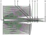
图1近地轨道具有米级地面分辨率的折反式可见光空间遥感相机的光路结构图;Fig. 1 The optical path structure diagram of the catadioptric visible light space remote sensing camera with meter-level ground resolution in low-Earth orbit;
图2近地轨道具有米级地面分辨率的折反式可见光空间遥感相机的点列图;Figure 2 The spot diagram of the catadioptric visible light space remote sensing camera with meter-level ground resolution in low-Earth orbit;
图3近地轨道具有米级地面分辨率的折反式可见光空间遥感相机的像面弥散斑均方根半径随波长变化的曲线图;Fig. 3 is a curve diagram of the RMS radius of the image plane diffuse spot of a catadioptric visible light space remote sensing camera with meter-level ground resolution in low-Earth orbit as a function of wavelength;
图4近地轨道具有米级地面分辨率的折反式可见光空间遥感相机的像面弥散斑均方根半径随视场变化的曲线图;Fig. 4 is a curve diagram of the RMS radius of the image plane diffuse spot of the catadioptric visible light space remote sensing camera with meter-level ground resolution in low-Earth orbit changing with the field of view;
图5近地轨道具有米级地面分辨率的折反式可见光空间遥感相机在20℃环境下的调制传递函数曲线图;Figure 5. Modulation transfer function curve of a catadioptric visible light space remote sensing camera with meter-level ground resolution in low-Earth orbit at 20°C;
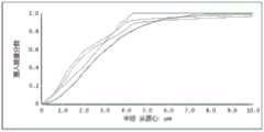
图6近地轨道具有米级地面分辨率的折反式可见光空间遥感相机的像面几何包围圆能量占比分数随半径变化的曲线图;Fig. 6. The curve diagram of the energy proportion of the geometric enclosing circle of the image surface of the catadioptric visible light space remote sensing camera with meter-level ground resolution in low-Earth orbit changing with the radius;
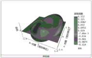
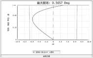
图7近地轨道具有米级地面分辨率的折反式可见光空间遥感相机在边缘视场下的像面波像差;Fig. 7 The image plane wave aberration of the catadioptric visible light space remote sensing camera with meter-level ground resolution in low-Earth orbit under the peripheral field of view;
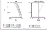
图8近地轨道具有米级地面分辨率的折反式可见光空间遥感相机的场曲像差曲线和畸变像差曲线;Fig. 8 The field curvature aberration curve and distortion aberration curve of the catadioptric visible light space remote sensing camera with meter-level ground resolution in low-Earth orbit;
图9近地轨道具有米级地面分辨率的折反式可见光空间遥感相机的像面弥散斑均方根半径随系统离焦量的变化曲线图;Fig. 9 is a graph showing the root mean square radius of the diffuse spot of the image plane of a catadioptric visible light space remote sensing camera with meter-level ground resolution in low-Earth orbit as a function of the defocus of the system;
图10近地轨道具有米级地面分辨率的折反式可见光空间遥感相机的轴向色差曲线图;Figure 10 Axial chromatic aberration curve of a catadioptric visible light space remote sensing camera with meter-level ground resolution in low-Earth orbit;
图11近地轨道具有米级地面分辨率的折反式可见光空间遥感相机的倍率色差曲线图;Figure 11 The chromatic aberration curve of the catadioptric visible light space remote sensing camera with meter-level ground resolution in low-Earth orbit;
图12近地轨道具有米级地面分辨率的折反式可见光空间遥感相机在-100℃环境下的像面弥散斑均方根半径随波长变化的曲线图;Fig. 12 The graph of the root mean square radius of the image plane diffuse spots changing with the wavelength of the catadioptric visible light space remote sensing camera with meter-level ground resolution in the low-Earth orbit in the environment of -100°C;
图13近地轨道具有米级地面分辨率的折反式可见光空间遥感相机在-100℃环境下的调制传递函数曲线图;Figure 13. Modulation transfer function curve of a catadioptric visible light space remote sensing camera with meter-level ground resolution in low-Earth orbit at -100°C;
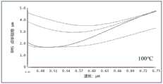
图14近地轨道具有米级地面分辨率的折反式可见光空间遥感相机在100℃环境下的像面弥散斑均方根半径随波长变化的曲线图;Fig. 14 The curve diagram of the root mean square radius of the image plane diffuse spot as a function of the wavelength of the catadioptric visible light space remote sensing camera with meter-level ground resolution in the low-Earth orbit under the environment of 100 °C;
图15近地轨道具有米级地面分辨率的折反式可见光空间遥感相机在100℃环境下的调制传递函数曲线图;Figure 15. Modulation transfer function curve of a catadioptric visible light space remote sensing camera with meter-level ground resolution in low-Earth orbit at 100°C;
其中,1—第一面主反射镜、2—第二面次反射镜、3—第三片透镜、4—第四片透镜、5—第五片透镜、6—第六片透镜、7—第七片透镜、8—第八面聚焦成像面。Among them, 1—the first main mirror, 2—the second mirror, 3—the third lens, 4—the fourth lens, 5—the fifth lens, 6—the sixth lens, 7— The seventh lens, the 8-8th surface focus on the imaging surface.
具体实施方式Detailed ways
为了使本发明的目的、技术方案及优点更加清楚明白,以下结合附图及实施例,对本发明进行进一步详细说明。应当理解,此处所描述的具体实施例仅用以解释本发明,并不用于限定本发明。In order to make the object, technical solution and advantages of the present invention clearer, the present invention will be further described in detail below in conjunction with the accompanying drawings and embodiments. It should be understood that the specific embodiments described here are only used to explain the present invention, not to limit the present invention.
如图1所示,本实施例公开的一种近地轨道米级地面分辨率的折反式可见光空间遥感相机,包括同轴排布的第一面主反射镜1、第二面次反射镜2、第三片透镜3、第四片透镜4、第五片透镜5、第六片透镜6、第七片透镜7、第八面聚焦成像面8。第一面主反射镜1和第二面次反射镜2均采用旋转双曲面型共同构成R-C双反系统,以实现对系统球差和彗差的校正,由于采用反射形式,R-C双反系统无色差。第三片透镜3、第四片透镜4、第五片透镜5、第六片透镜6和第七片透镜7构成后置五片式球面透镜组,通过镜片的光焦度分配实现色差、离轴像散的校正,同时利用具有不同折射率系数的五种光学材料实现对热离焦的补偿。第八面为聚焦成像面8,是探测器所在的位置。As shown in Figure 1, a catadioptric visible light space remote sensing camera with meter-level ground resolution in low-earth orbit disclosed in this embodiment includes a first
第一面主反射镜1表面曲率半径为-1453.83mm~-1452.94mm,二次项系数为-1.069~-1.064,主反射镜外直径不小于600mm,主反射镜中心开孔半径为74~76mm,距离第二面次反射镜2的距离为557.70mm~557.80mm,材料为SiC;The surface curvature radius of the first
优选第一面主反射镜1表面曲率半径为-1453.385mm,二次项系数为-1.067,反射镜口径为直径600mm,中心开孔半径为75mm,距离第二面次反射镜2的距离为557.76mm,材料为SiC。Preferably, the radius of curvature of the surface of the first
第二面次反射镜2表面曲率半径为-434.67mm~-433.79mm,二次项系数为-3.106~-3.101,次反射镜直径为150mm~144mm,距离第三片透镜3前表面的距离为479.9mm~480.1mm,材料为SiC;优选第二面次反射镜2表面曲率半径为-434.23mm,二次项系数为-3.104,次反射镜直径为152mm,距离第三片透镜3前表面的距离为480mm,材料为SiC。The radius of curvature of the surface of the
第三片透镜3厚度为29.72mm~30.20mm,前表面曲率半径为153.04mm~153.52mm,后表面曲率半径为116.62mm~117.11mm,距离第四片透镜4前表面距离为21.10mm~21.14mm,材料为N-PSK57;优选第三片透镜3厚度为30.00mm,前表面曲率半径为153.294mm,后表面曲率半径为116.858mm,距离第四片透镜4前表面距离为21.12mm,材料为N-PSK57。The thickness of the
第四片透镜4厚度为29.72mm~30.20mm,前表面曲率半径为335.35mm~335.86mm,后表面曲率半径为709.162mm~709.66mm,距离第四片透镜4前表面距离为24.79mm~24.83mm,材料为N-KZFS11;优选第四片透镜4厚度为30.00mm,前表面曲率半径为335.605mm,后表面曲率半径为709.402mm,距离第五片透镜5前表面距离为24.81mm,材料为N-KZFS11。The thickness of the
第五片透镜5为平板玻璃厚度为24.98mm~25.02mm,距离第六片透镜6前表面距离为24.88mm~24.92mm,材料为H-K9L;优选第五片透镜5厚度为25mm,距离第六片透镜6前表面距离为24.90mm,材料为H-K9L。The
第六片透镜6厚度为24.62mm~25.13mm,前表面曲率半径为-309.881mm~-309.394mm,后表面曲率半径为98.767mm~99.245mm,距离第七片透镜7前表面的距离为21.78mm~21.82mm,材料为N-FK51A;优选第六片透镜6厚度为25.00mm,前表面曲率半径为-309.631mm,后表面曲率半径为99.008mm,距离第七片透镜7前表面的距离为21.80mm,材料为N-FK51A。The thickness of the
第七片透镜7厚度为29.72mm~30.20mm,前表面曲率半径为110.228mm~110.732mm,后表面曲率半径为220.156mm~220.652mm,距离第八面聚焦成像表面8的距离为151.30mm~151.35mm,材料为BK3;优选第七片透镜7厚度为30.00mm,前表面曲率半径为110.481mm,后表面曲率半径为220.399mm,距离第八面聚焦成像表面8的距离为151.33mm,材料为BK3。The thickness of the
所述的第八面为聚焦成像面8,可选用规格为7680×7680,像元尺寸为10μm的可见光探测器件。The eighth surface is the focusing
进一步地,本发明实施例的近地轨道具有米级地面分辨率的折反式可见光空间遥感相机的运行轨道高度为500km,观测波段为0.45μm~0.75μm,系统焦距5400mm,相对孔径为1:9,全视场为0.8°×0.8°,单景观幅宽度为7km×7km,地面像元分辨率0.93m,相机系统透镜组总质量仅为2.63kg,系统总长小于900mm,探测器规格7680×7680,像元尺寸10μm。Further, the catadioptric visible light space remote sensing camera with meter-level ground resolution in the low-Earth orbit of the embodiment of the present invention has an orbital height of 500 km, an observation band of 0.45 μm to 0.75 μm, a system focal length of 5400 mm, and a relative aperture of 1: 9. The full field of view is 0.8°×0.8°, the single view width is 7km×7km, the ground pixel resolution is 0.93m, the total mass of the lens group of the camera system is only 2.63kg, the total length of the system is less than 900mm, and the detector specification is 7680× 7680, pixel size 10μm.
本实施例公开的一种近地轨道米级地面分辨率的折反式可见光空间遥感相机的工作方法为:The working method of a catadioptric visible light space remote sensing camera with meter-level ground resolution in low-earth orbit disclosed in this embodiment is as follows:
近地轨道米级地面分辨率的折反式可见光空间遥感相机探测可见光目标,入射的可见光光束经第一面主反射镜1、第二面次反射镜2两次反射实现对可见光束的球差和彗差校正,由于采用R-C两反系统使空间遥感相机具有大光学口径,以提高空间遥感相机的灵敏度。在后置五片式球面透镜组中,通过匹配第三片透镜3、第四片透镜4、第五片透镜5、第六片透镜6和第七片透镜7的玻璃折射率、镜片光焦度以及镜筒结构的膨胀系数,实现对从R-C两反系统出射的可见光束的热像差和色差校正,以提高成像质量,使成像性能接近衍射极限。The catadioptric visible light space remote sensing camera with meter-level ground resolution in low-Earth orbit detects visible light targets, and the incident visible light beam is reflected twice by the first
图2为本发明实施例近地轨道具有米级地面分辨率的折反式可见光空间遥感相机系统在全视场下的像面弥散斑分布图,图3为本发明实例近地轨道具有米级地面分辨率的折反式可见光空间遥感相机系统像面上的弥散斑均方根半径随视场的变化曲线图,图4为本发明实施例近地轨道具有米级地面分辨率的折反式可见光空间遥感相机的像面弥散斑均方根半径随视场变化的曲线图,图5为本发明实施例近地轨道具有米级地面分辨率的折反式可见光空间遥感相机在20℃环境下的调制传递函数曲线图,图6为本发明实施例近地轨道具有米级地面分辨率的折反式可见光空间遥感相机的像面包围圆能量占比分数随半径变化的曲线图。图2~图6的曲线图均表明本发明实施例可见光空间遥感相机系统的成像质量接近衍射极限。Fig. 2 is the image plane diffuse speckle distribution diagram of the catadioptric visible light space remote sensing camera system with meter-level ground resolution in the low-earth orbit of the embodiment of the present invention under the full field of view, and Fig. 3 is the example of the present invention. The catadioptric visible light space remote sensing camera system with ground resolution shows the change curve of the root mean square radius of the diffuse spot on the image surface with the field of view. The graph of the root mean square radius of the image plane diffuse spot of the visible light space remote sensing camera changing with the field of view, Fig. 5 is a catadioptric visible light space remote sensing camera with meter-level ground resolution in the low earth orbit of the embodiment of the present invention under the environment of 20 °C Fig. 6 is a curve diagram of the energy ratio of the enclosing circle of the image surface of a catadioptric visible light space remote sensing camera with meter-level ground resolution in low-Earth orbit according to an embodiment of the present invention. The graphs in FIGS. 2 to 6 all show that the imaging quality of the visible light space remote sensing camera system of the embodiment of the present invention is close to the diffraction limit.
图7为本发明实施例近地轨道具有米级地面分辨率的折反式可见光空间遥感相机在边缘视场下的像面波像差,图8为本发明实施例近地轨道具有米级地面分辨率的折反式可见光空间遥感相机的场曲像差曲线和畸变像差曲线,图9为本发明实施例近地轨道具有米级地面分辨率的折反式可见光空间遥感相机的像面弥散斑均方根半径随系统离焦量的变化曲线图,图10为本发明实施例近地轨道具有米级地面分辨率的折反式可见光空间遥感相机的轴向色差曲线图,图11为本发明实施例近地轨道具有米级地面分辨率的折反式可见光空间遥感相机的倍率色差曲线图。图7~图11的曲线图均表明本发明实施例可见光空间遥感相机系统的场曲、畸变、离焦、轴向色差以及倍率色差实现了很好的校正,系统的波像差远优于瑞利判据准则。Figure 7 shows the image plane wave aberration of the catadioptric visible light space remote sensing camera with meter-level ground resolution in the low-Earth orbit of the embodiment of the present invention under the peripheral field of view, and Figure 8 shows the embodiment of the present invention in the near-Earth orbit with the meter-level ground The field curvature aberration curve and the distortion aberration curve of the high-resolution catadioptric visible light space remote sensing camera, Fig. 9 is the image plane dispersion of the catadioptric visible light space remote sensing camera with meter-level ground resolution in the low-Earth orbit of the embodiment of the present invention The change curve of the root mean square radius of the spot with the defocus of the system, Fig. 10 is the axial chromatic aberration curve of the catadioptric visible light space remote sensing camera with meter-level ground resolution in the low earth orbit of the embodiment of the present invention, and Fig. 11 is the graph Embodiment of the invention The chromatic aberration curve of magnification of a catadioptric visible light space remote sensing camera with meter-level ground resolution in low earth orbit. The graphs in Figures 7 to 11 all show that the field curvature, distortion, defocus, axial chromatic aberration, and magnification chromatic aberration of the visible light space remote sensing camera system of the embodiment of the present invention have been well corrected, and the wave aberration of the system is far better than that of Rui Profit criterion.
图12为本发明实施例近地轨道具有米级地面分辨率的折反式可见光空间遥感相机在-100℃环境下的像面弥散斑均方根半径随波长变化的曲线图,图13为本发明实施例近地轨道具有米级地面分辨率的折反式可见光空间遥感相机在-100℃环境下的调制传递函数曲线图,图14为本发明实施例近地轨道具有米级地面分辨率的折反式可见光空间遥感相机在100℃环境下的像面弥散斑均方根半径随波长变化的曲线图,图15为本发明实施例近地轨道具有米级地面分辨率的折反式可见光空间遥感相机在100℃环境下的调制传递函数曲线图。图12~图15的曲线图均表明本发明实施例可见光空间遥感相机系统在-100℃~100℃的温度下的调制传递函数均接近衍射极限,成像质量良好。Fig. 12 is a curve diagram of the root mean square radius of the image plane diffusion spot changing with the wavelength of the catadioptric visible light space remote sensing camera with meter-level ground resolution in the low-earth orbit of the embodiment of the present invention under the environment of -100 ° C, and Fig. 13 is the graph. The modulation transfer function curve of the catadioptric visible light space remote sensing camera with meter-level ground resolution in the low-Earth orbit of the embodiment of the invention under the environment of -100°C. The graph of the root mean square radius of the image plane dispersion spot changing with the wavelength of the catadioptric visible light space remote sensing camera in the environment of 100°C, Fig. 15 is the catadioptric visible light space with meter-level ground resolution in the low earth orbit of the embodiment of the present invention The modulation transfer function curve of the remote sensing camera at 100°C. The graphs in Fig. 12 to Fig. 15 all show that the modulation transfer function of the visible light space remote sensing camera system of the embodiment of the present invention is close to the diffraction limit at a temperature of -100°C to 100°C, and the imaging quality is good.
综上所述,本发明的近地轨道具有米级地面分辨率的折反式可见光空间遥感相机,采用折反射式结构有效地增大了系统光学口径,同时减小了系统的体积和重量。通过光学材料和结构材料的合理搭配以及透镜组光焦度的合理分配降低温度变化对光学系统性能的影响,系统在较宽的温度范围内具有良好的成像质量,环境适应性优异。本发明可以应用于可见光遥感对地观测领域。To sum up, the catadioptric visible light space remote sensing camera with meter-level ground resolution in low-Earth orbit of the present invention adopts a catadioptric structure to effectively increase the optical aperture of the system while reducing the volume and weight of the system. The influence of temperature changes on the performance of the optical system is reduced through the reasonable combination of optical materials and structural materials and the reasonable distribution of the focal power of the lens group. The system has good imaging quality in a wide temperature range and excellent environmental adaptability. The invention can be applied to the field of visible light remote sensing and earth observation.
以上所述的具体描述,对发明的目的、技术方案和有益效果进行了进一步详细说明,所应理解的是,以上所述仅为本发明的具体实施例而已,并不用于限定本发明的保护范围,凡在本发明的精神和原则之内,所做的任何修改、等同替换、改进等,均应包含在本发明的保护范围之内。The specific description above further elaborates the purpose, technical solution and beneficial effect of the invention. It should be understood that the above description is only a specific embodiment of the present invention and is not used to limit the protection of the present invention. Any modification, equivalent replacement, improvement, etc. made within the spirit and principle of the present invention shall be included in the protection scope of the present invention.
Claims (10)
Translated fromChinesePriority Applications (1)
| Application Number | Priority Date | Filing Date | Title |
|---|---|---|---|
| CN202211249579.6ACN115793219A (en) | 2022-10-12 | 2022-10-12 | Refraction-reflection type visible light space remote sensing camera for near-earth orbit meter-level ground resolution |
Applications Claiming Priority (1)
| Application Number | Priority Date | Filing Date | Title |
|---|---|---|---|
| CN202211249579.6ACN115793219A (en) | 2022-10-12 | 2022-10-12 | Refraction-reflection type visible light space remote sensing camera for near-earth orbit meter-level ground resolution |
Publications (1)
| Publication Number | Publication Date |
|---|---|
| CN115793219Atrue CN115793219A (en) | 2023-03-14 |
Family
ID=85432898
Family Applications (1)
| Application Number | Title | Priority Date | Filing Date |
|---|---|---|---|
| CN202211249579.6APendingCN115793219A (en) | 2022-10-12 | 2022-10-12 | Refraction-reflection type visible light space remote sensing camera for near-earth orbit meter-level ground resolution |
Country Status (1)
| Country | Link |
|---|---|
| CN (1) | CN115793219A (en) |
Cited By (1)
| Publication number | Priority date | Publication date | Assignee | Title |
|---|---|---|---|---|
| CN118759704A (en)* | 2024-06-28 | 2024-10-11 | 中国科学院上海技术物理研究所 | A catadioptric optical system for infrared star sensor |
Citations (6)
| Publication number | Priority date | Publication date | Assignee | Title |
|---|---|---|---|---|
| US5471346A (en)* | 1992-03-13 | 1995-11-28 | Lockheed Missiles & Space Co., Inc. | Casegrain telescope with spherical mirror surfaces |
| CN102520506A (en)* | 2011-12-30 | 2012-06-27 | 中国科学院长春光学精密机械与物理研究所 | Compact catadioptric long-wave infrared athermal imaging optical system |
| RU2650055C1 (en)* | 2017-02-08 | 2018-04-06 | Акционерное общество "Новосибирский приборостроительный завод" | Catadioptric telescope |
| CN109633879A (en)* | 2018-12-17 | 2019-04-16 | 中国科学院西安光学精密机械研究所 | A kind of High Resolution Visible Light medium-wave infrared two waveband optical imaging system |
| CN111487756A (en)* | 2020-04-26 | 2020-08-04 | 北京空间机电研究所 | A small volume imaging optical system based on catadioptric long focal length and large field of view |
| CN114236796A (en)* | 2021-12-17 | 2022-03-25 | 中国科学院长春光学精密机械与物理研究所 | Visible light-medium wave infrared afocal optical system |
- 2022
- 2022-10-12CNCN202211249579.6Apatent/CN115793219A/enactivePending
Patent Citations (6)
| Publication number | Priority date | Publication date | Assignee | Title |
|---|---|---|---|---|
| US5471346A (en)* | 1992-03-13 | 1995-11-28 | Lockheed Missiles & Space Co., Inc. | Casegrain telescope with spherical mirror surfaces |
| CN102520506A (en)* | 2011-12-30 | 2012-06-27 | 中国科学院长春光学精密机械与物理研究所 | Compact catadioptric long-wave infrared athermal imaging optical system |
| RU2650055C1 (en)* | 2017-02-08 | 2018-04-06 | Акционерное общество "Новосибирский приборостроительный завод" | Catadioptric telescope |
| CN109633879A (en)* | 2018-12-17 | 2019-04-16 | 中国科学院西安光学精密机械研究所 | A kind of High Resolution Visible Light medium-wave infrared two waveband optical imaging system |
| CN111487756A (en)* | 2020-04-26 | 2020-08-04 | 北京空间机电研究所 | A small volume imaging optical system based on catadioptric long focal length and large field of view |
| CN114236796A (en)* | 2021-12-17 | 2022-03-25 | 中国科学院长春光学精密机械与物理研究所 | Visible light-medium wave infrared afocal optical system |
Non-Patent Citations (2)
| Title |
|---|
| 孙雯 等: "新型两镜折反式平场消像散望远物镜光学设计", 红外与激光工程, no. 12, 25 December 2015 (2015-12-25)* |
| 宋晓东 等: "大视场空间对地遥感卡塞格林光学系统设计", 光学与光电技术, no. 03, 10 June 2012 (2012-06-10)* |
Cited By (2)
| Publication number | Priority date | Publication date | Assignee | Title |
|---|---|---|---|---|
| CN118759704A (en)* | 2024-06-28 | 2024-10-11 | 中国科学院上海技术物理研究所 | A catadioptric optical system for infrared star sensor |
| CN118759704B (en)* | 2024-06-28 | 2025-06-13 | 中国科学院上海技术物理研究所 | A catadioptric optical system for infrared star sensor |
Similar Documents
| Publication | Publication Date | Title |
|---|---|---|
| RU2683820C2 (en) | Telescope and telescope array for use in spacecraft | |
| CN102508361A (en) | Spatial large view field, superwide spectral band and multispectral imaging optical system | |
| CN103344334B (en) | Based on having intermediary image from the anti-wide spectral multi channel imaging optical system of axle three | |
| CN103345051B (en) | Bimodulus refraction-reflection is detector image-forming system altogether | |
| CN102866487B (en) | Coaxial four surpass in reverse low distorted optical system | |
| CN106371200B (en) | The big visual field heavy caliber of broadband rolls over three anti-non-focus optical system of axis | |
| CN204666945U (en) | A kind of binary channels imaging optical system adopting right-angle reflecting prism | |
| CN103345050B (en) | Space refraction and reflection type multichannel imaging optical system | |
| CN103345062B (en) | High resolution stereo mapping and reconnaissance integrated camera optical system | |
| CN110579859B (en) | Telecentric optical system of compact long-focal-length star sensor | |
| CN108152973A (en) | A kind of visible ray and medium-wave infrared Shared aperture complex optics | |
| CN102062936B (en) | Off-axis TMA optical system for reducing processing and resetting difficulty | |
| CN109143558B (en) | A miniaturized all-weather star sensor optical system | |
| CN102252756A (en) | Front-mounted optical system of satellite-borne differential absorption spectrometer | |
| CN109283671B (en) | A light, small, large field of view and low distortion quasi-coaxial five-mirror optical system | |
| CN110262024A (en) | A kind of novel coaxial four surpasses in reverse compact optical system | |
| CN116577921A (en) | Large-aperture coaxial three-mirror optical system and its ultra-lightweight silicon carbide mirror assembly | |
| CN102364372A (en) | Multispectral refraction-reflection type optical system | |
| CN115793219A (en) | Refraction-reflection type visible light space remote sensing camera for near-earth orbit meter-level ground resolution | |
| CN111896480A (en) | An Off-axis Broadband Reflective Simultaneous Polarization Imaging System | |
| CN114326070A (en) | Large-caliber long-focus multispectral short-wave infrared optical system | |
| CN211603682U (en) | Optical system of ultra-wide-spectrum long-focal-distance star sensor | |
| CN113311577A (en) | Free-form surface off-axis two-reflection telescope objective system with compact structure | |
| CN108873280B (en) | Off-axis catadioptric medium-long wave infrared system based on spherical reflector | |
| CN110703410B (en) | An unobstructed long focal length star sensor optical system |
Legal Events
| Date | Code | Title | Description |
|---|---|---|---|
| PB01 | Publication | ||
| PB01 | Publication | ||
| SE01 | Entry into force of request for substantive examination | ||
| SE01 | Entry into force of request for substantive examination |