CN115778453A - Incision spreader for trauma orthopedic surgery - Google Patents
Incision spreader for trauma orthopedic surgeryDownload PDFInfo
- Publication number
- CN115778453A CN115778453ACN202211407844.9ACN202211407844ACN115778453ACN 115778453 ACN115778453 ACN 115778453ACN 202211407844 ACN202211407844 ACN 202211407844ACN 115778453 ACN115778453 ACN 115778453A
- Authority
- CN
- China
- Prior art keywords
- sleeve
- frame
- knob
- movable
- fixed
- Prior art date
- Legal status (The legal status is an assumption and is not a legal conclusion. Google has not performed a legal analysis and makes no representation as to the accuracy of the status listed.)
- Pending
Links
Images


Landscapes
- Surgical Instruments (AREA)
Abstract
Translated fromChinese
Description
Translated fromChinese技术领域technical field
本发明涉及医疗器械技术领域,更具体地说,涉及一种创伤骨科手术切口撑开器。The invention relates to the technical field of medical instruments, in particular to an incision spreader for traumatic orthopedic surgery.
背景技术Background technique
创伤骨科就是骨科学的一个细小的分支,面向的人群为各种创伤性疾病。比如上臂的骨折、下肢的骨折、脊柱的骨折以及其他部位的骨折等,所面临的人群主要是以各种骨折为主。Traumatology orthopedics is a small branch of orthopedics, which targets various traumatic diseases. For example, fractures of the upper arm, lower limbs, spine, and other parts of the body.
在创伤骨科手术时,需要将患者骨折处的皮肤表面切开,从而便于持刀医生对患者进行骨骼修复,在现有的骨科手术中,将皮肤肌肉切口后通常使用手术拉钩将皮肤肌肉向两边拉住,由此才可进一步开展手术,但是现有的手术拉钩在使用的过程中,一般都是通过医护人员手持手术拉钩将手术切口向两边拉开,从而导致需要至少两名医护人员进行操作,造成人力资源浪费的同时,还可能影响持刀医生的手术操作,同时,由于人体肌肉的收缩力度较大,导致在牵拉手术拉钩时较为吃力,甚至在长时间的手术时,需要替换医护人员牵拉手术拉钩,如果采用设备代替人手,则导致较与人手的灵活度较差,使得撑开的方向不能准确的垂直于手术切口,从而导致切口在撑开时设备贴近切口的一侧距离较长,进而使得距离较短的一侧观察不够全面,继续撑开时,则可能导致对患者身体组织造成损伤。In traumatic orthopedic surgery, it is necessary to incise the skin surface of the patient's fracture, so that the doctor holding the knife can repair the patient's bone. In the existing orthopedic surgery, the skin and muscle are usually incised with surgical retractors to both sides. Only then can the operation be carried out further, but in the process of using the existing surgical retractor, the surgical incision is generally opened to both sides by the medical staff holding the surgical retractor, which requires at least two medical staff to operate , while causing waste of human resources, it may also affect the surgical operation of the doctor holding the knife. At the same time, due to the strong contraction of human muscles, it is more difficult to pull the surgical retractor, and even in a long operation, it is necessary to replace the medical staff. If the staff pulls the surgical retractor, if the device is used instead of the human hand, it will result in poorer flexibility than the human hand, so that the direction of stretching cannot be accurately perpendicular to the surgical incision, resulting in the distance between the equipment and the side of the incision when the incision is stretched. It is longer, so that the observation on the side with a shorter distance is not comprehensive enough, and when it continues to be stretched, it may cause damage to the patient's body tissue.
基于此,本发明设计了创伤骨科手术切口撑开器,以解决上述问题。Based on this, the present invention designs a trauma orthopedic surgery incision spreader to solve the above problems.
发明内容Contents of the invention
1.要解决的技术问题1. Technical problems to be solved
本发明的目的在于提供一种创伤骨科手术切口撑开器,以解决上述背景技术中提出的问题。The purpose of the present invention is to provide an incision spreader for traumatic orthopedic surgery to solve the problems raised in the above-mentioned background technology.
2.技术方案2. Technical solution
一种创伤骨科手术切口撑开器,包括撑开架,所述撑开架的内腔通过轴承连接有螺纹杆一,所述螺纹杆一沿中部对称设置有螺纹方向相反的外螺纹一和外螺纹二,所述撑开架的外侧连接有旋钮一,所述旋钮一与螺纹杆一的端部相连接,所述外螺纹一和外螺纹二的外侧均连接有活动架,所述活动架的外侧滑动连接有活动块,所述活动块靠近撑开架侧面的一侧设置有调节组件,所述调节组件的下方连接有拉钩,所述撑开架的背面连接有贴合组件,所述贴合组件的外侧连接有固定组件。An incision spreader for traumatic orthopedic surgery, comprising a spreader frame, the inner cavity of the spreader frame is connected with a threaded rod 1 through bearings, and the threaded rod 1 is symmetrically provided with
优选地,所述调节组件包括与活动块相固定的调节盒,所述调节盒的内腔连接有固定板,所述固定板的中部连接有螺纹杆二,所述螺纹杆二的外侧螺纹连接有螺纹套筒,所述螺纹套筒的底端贯穿调节盒并连接有连接板,所述连接板与拉钩相连接;所述固定板的上方连接有锥形齿轮一,所述锥形齿轮一贯穿固定板并与螺纹杆二相连接,且锥形齿轮一的外沿啮合有锥形齿轮二,所述调节盒的外侧连接有旋钮二,所述旋钮二贯穿调节盒并与锥形齿轮二相连接。Preferably, the adjustment assembly includes an adjustment box fixed to the movable block, the inner cavity of the adjustment box is connected with a fixed plate, the middle part of the fixed plate is connected with a threaded rod two, and the outer side of the threaded rod two is threaded There is a threaded sleeve, and the bottom end of the threaded sleeve runs through the adjustment box and is connected with a connecting plate, and the connecting plate is connected with the pull hook; a bevel gear one is connected above the fixing plate, and the bevel gear one It runs through the fixing plate and is connected with the threaded
优选地,所述螺纹套筒的外侧设置有限位块,所述螺纹套筒通过限位块与调节盒滑动连接。Preferably, a limit block is provided on the outside of the threaded sleeve, and the threaded sleeve is slidably connected with the adjustment box through the limit block.
优选地,所述贴合组件包括与固定组件相连接的调节架,所述调节架的内腔通过轴承连接有螺纹杆三,所述螺纹杆三的外侧连接有活动座,所述活动座的侧面连接有固定套筒,所述固定套筒的内腔套接有连接柱,所述连接柱与撑开架相连接,且连接柱的外侧开设有若干限位孔一,所述固定套筒的外侧连接有连接筒一,所述连接筒一的内腔滑动连接有限位杆一,所述限位杆一的外侧连接有安装环,所述安装环的上方连接有弹簧,所述弹簧的两端分别与连接筒一和安装环相连接。Preferably, the fitting assembly includes an adjustment frame connected with the fixed assembly, the inner cavity of the adjustment frame is connected with a threaded rod three through bearings, and the outer side of the threaded rod three is connected with a movable seat, and the movable seat The side is connected with a fixed sleeve, and the inner cavity of the fixed sleeve is sleeved with a connecting column. The outer side is connected with a connecting cylinder 1, and the inner cavity of the connecting cylinder 1 is slidably connected with the limiting rod 1, and the outer side of the limiting rod 1 is connected with a mounting ring, and a spring is connected above the mounting ring, and the two ends of the spring The ends are respectively connected with the connecting cylinder one and the installation ring.
优选地,所述贴合组件还包括与螺纹杆三的端部相连接的连接套筒,所述连接套筒的内腔设置有活动柱,所述活动柱的外侧有导向块,且连接套筒的内壁上开设有导向槽,所述活动柱通过导向块和导向槽与连接套筒滑动连接,所述活动柱的端部贯穿连接套筒并连接有旋钮三,且活动柱位于连接套筒的外侧设置有轴承套,所述活动柱通过轴承套连接有连接件,所述调节架的上方滑动连接有齿板一,所述连接件与齿板一相连接,且齿板一的下方设置有齿板二,所述齿板一和齿板二的接触面上均设置有相同的凸齿,所述齿板二的下方连接有伸缩杆,所述伸缩杆与调节架的外侧相连接。Preferably, the fitting assembly also includes a connecting sleeve connected to the end of the threaded rod three, the inner cavity of the connecting sleeve is provided with a movable column, and the outer side of the movable column has a guide block, and the connecting sleeve There is a guide groove on the inner wall of the barrel, and the movable column is slidably connected with the connecting sleeve through the guide block and the guide groove. A bearing sleeve is provided on the outer side of the bearing sleeve, and the movable column is connected with a connecting piece through the bearing sleeve. A tooth plate 1 is slidably connected to the top of the adjustment frame. The connecting piece is connected with the tooth plate 1, and the bottom of the tooth plate 1 is set There is a second tooth plate, the contact surfaces of the first tooth plate and the second tooth plate are provided with the same protruding teeth, the bottom of the second tooth plate is connected with a telescopic rod, and the telescopic rod is connected with the outside of the adjustment frame.
优选的,所述旋钮三靠近调节架的一侧开设有若干限位孔二,所述调节架靠近旋钮三的一侧设置有限位杆二,所述限位杆二延伸至限位孔二的内部但不与其连接。Preferably, the side of the knob three close to the adjustment frame is provided with a number of limit holes two, and the side of the adjustment frame close to the knob three is provided with a limit rod two, and the limit rod two extends to the end of the limit hole two internal but not connected to it.
优选的,所述固定组件包括与调节架相连接的固定盒,所述固定盒的外侧连接有绑带,所述绑带的另一端贯穿固定盒并与其活动连接,且绑带上设置有齿条,所述固定盒的内腔连接有圆形齿轮,所述圆形齿轮与齿条相啮合,且圆形齿轮的外侧连接有连接筒二,所述连接筒二的内腔连接有活动件,所述活动件的外侧连接有固定块,所述连接筒二上贯穿开设有通槽,所述活动件通过固定块和通槽与连接筒二滑动连接,所述活动件的端部贯穿固定盒并连接有旋钮四,所述旋钮四靠近固定盒的一侧连接有限位杆三,所述固定盒的外侧开设有若干限位孔三,所述限位孔三延伸至限位杆三的内腔但不与其连接。Preferably, the fixing assembly includes a fixing box connected with the adjustment frame, a strap is connected to the outside of the fixing box, the other end of the strap runs through the fixing box and is movably connected with it, and the strap is provided with teeth The inner cavity of the fixed box is connected with a circular gear, the circular gear is meshed with the rack, and the outer side of the circular gear is connected with a connecting cylinder two, and the inner cavity of the connecting cylinder two is connected with a movable part , the outer side of the movable part is connected with a fixed block, and a through groove is opened through the second connecting cylinder, the movable part is slidably connected with the second connecting cylinder through the fixed block and the through groove, and the end of the movable part penetrates through the fixed The box is also connected with a knob 4, the side of the knob 4 close to the fixed box is connected with the
3.有益效果3. Beneficial effect
相比于现有技术,本发明的优点在于:Compared with the prior art, the present invention has the advantages of:
1)、本发明中,通过设置调节组件,使得能够控制拉钩上下移动,从而使得该装置能够对不同深度的手术切口进行撑开,避免在手术中需要根据手术切口的深度,更换不同规格的手术拉钩,进而降低了手术的操作时长,提高手术效率。1) In the present invention, by setting the adjustment component, the pull hook can be controlled to move up and down, so that the device can open the surgical incisions of different depths, avoiding the need to replace surgical incisions of different specifications according to the depth of the surgical incisions during the operation. The retractor reduces the operation time of the operation and improves the operation efficiency.
2)、本发明中,通过设置贴合组件,使得拉钩的撑开方向能够垂直于手术切口,从而避免切口一侧拉伸较长,另一侧拉伸较短的问题,从而便于持刀医生能够更好的对骨骼进行观察修复,同时也避免了在牵拉手术切口时,由于过度拉伸导致对患者的身体组织造成损伤。2) In the present invention, by arranging the fitting components, the stretching direction of the retractor can be perpendicular to the surgical incision, thereby avoiding the problem that one side of the incision is stretched longer and the other side is stretched shorter, so that it is convenient for the doctor holding the knife It can better observe and repair the bone, and at the same time avoid damage to the patient's body tissue due to excessive stretching when pulling the surgical incision.
3)、本发明中,通过设置固定组件,使得该装置能够固定于患者肢体上,从而避免在牵拉手术切口时,需要医护人员进行牵拉,降低了医护人员的操作难度,同时,通过调节圆形齿轮带动绑带移动,使得该装置能够固定在不同患者的不同肢体处,从而提高了该装置的实用性。3) In the present invention, by setting the fixing component, the device can be fixed on the patient's limb, thereby avoiding the need for medical personnel to pull when pulling the surgical incision, reducing the difficulty of operation of the medical personnel, and at the same time, by adjusting The circular gears drive the straps to move, so that the device can be fixed on different limbs of different patients, thereby improving the practicability of the device.
4)、综上所述,该装置能够使得在进行骨科手术时,便于将手术切口撑开并固定,从而避免医护人员在牵拉手术拉钩时较为吃力,降低了医护人员的操作难度,同时还能够将手术切口对称撑开,从而便于持刀医生对患者骨折处进行观察,进而便于持刀医生进行骨骼修复工作,提高了该装置的实用性能。4) In summary, the device can make it easier to stretch and fix the surgical incision during orthopedic surgery, thereby avoiding the medical staff's difficulty in pulling the surgical retractor, reducing the difficulty of the medical staff's operation, and at the same time The surgical incision can be symmetrically stretched, so that it is convenient for the doctor holding the knife to observe the patient's fracture, and then it is convenient for the doctor holding the knife to perform bone repair work, and the practical performance of the device is improved.
附图说明Description of drawings
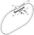
图1为本发明的整体结构示意图;Fig. 1 is the overall structure schematic diagram of the present invention;
图2为本发明的固定组件结构局部示意图;Fig. 2 is a partial schematic view of the structure of the fixing assembly of the present invention;
图3为本发明图2中A处结构放大图;Fig. 3 is the enlarged view of the structure at A place in Fig. 2 of the present invention;
图4为本发明的贴合组件结构示意图;Fig. 4 is a structural schematic diagram of the bonding assembly of the present invention;
图5为本发明图4中B处结构放大图;Fig. 5 is the enlarged view of the structure at B place in Fig. 4 of the present invention;
图6为本发明的旋钮三结构示意图;Fig. 6 is a structural schematic diagram of three knobs of the present invention;
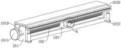
图7为本发明的撑开架结构示意图;Fig. 7 is a structural schematic diagram of the expansion frame of the present invention;
图8为本发明的调节盒结构剖视图。Fig. 8 is a cross-sectional view of the structure of the adjustment box of the present invention.
图中标号说明:1、撑开架;2、螺纹杆一;3、外螺纹一;4、外螺纹二;5、旋钮一;6、活动架;7、活动块;8、调节组件;81、调节盒;82、固定板;83、螺纹杆二;84、螺纹套筒;85、限位块;86、连接板;87、锥形齿轮一;88、锥形齿轮二;89、旋钮二;9、拉钩;10、贴合组件;101、调节架;102、螺纹杆三;103、活动座;104、固定套筒;105、连接柱;106、限位孔一;107、连接筒一;108、限位杆一;109、安装环;1010、弹簧;1011、连接套筒;1012、活动柱;1013、导向块;1014、导向槽;1015、旋钮三;1016、限位孔二;1017、限位杆二;1018、轴承套;1019、连接件;1020、齿板一;1021、齿板二;1022、伸缩杆;11、固定组件;111、固定盒;112、绑带;113、齿条;114、圆形齿轮;115、连接筒二;116、活动件;117、固定块;118、通槽;119、旋钮四;1110、限位杆三;1111、限位孔三。Explanation of the symbols in the figure: 1. Expansion frame; 2. Thread rod one; 3. External thread one; 4. External thread two; 5. Knob one; 6. Movable frame; 7. Movable block; 8. Adjustment assembly; 81 Adjusting box; 82, fixed plate; 83, threaded rod two; 84, threaded sleeve; 85, limit block; 86, connecting plate; 87, bevel gear one; 88, bevel gear two; 89, knob two; 9. Pull hook; 10. Fitting component; 101. Adjusting frame; 102. Threaded rod three; 103. Movable seat; 104. Fixed sleeve; 105. Connecting column; 106. Limiting hole one; 107. Connecting cylinder one; 108, limit rod one; 109, installation ring; 1010, spring; 1011, connecting sleeve; 1012, movable column; 1013, guide block; 1014, guide groove; 1015, knob three; 1016, limit hole two; , limit rod two; 1018, bearing sleeve; 1019, connector; 1020, tooth plate one; 1021, tooth plate two; 1022, expansion rod; 11, fixed component; 111, fixed box; 112, strap; 114, circular gear; 115, connecting tube two; 116, movable part; 117, fixed block; 118, through groove; 119, knob four; 1110, limit rod three;
具体实施方式Detailed ways
在本发明的描述中,需要理解的是,术语“中心”、“纵向”、“横向”、“长度”、“宽度”、“厚度”、“上”、“下”、“前”、“后”、“左”、“右”、“竖直”、“水平”、“顶”、“底”、“内”、“外”、“顺时针”、“逆时针”等指示的方位或位置关系为基于附图所示的方位或位置关系,仅是为了便于描述本发明和简化描述,而不是指示或暗示所指的设备或元件必须具有特定的方位、以特定的方位构造和操作,因此不能理解为对本发明的限制。In describing the present invention, it should be understood that the terms "center", "longitudinal", "transverse", "length", "width", "thickness", "upper", "lower", "front", " Orientation indicated by rear, left, right, vertical, horizontal, top, bottom, inside, outside, clockwise, counterclockwise, etc. The positional relationship is based on the orientation or positional relationship shown in the drawings, and is only for the convenience of describing the present invention and simplifying the description, rather than indicating or implying that the referred device or element must have a specific orientation, be constructed and operated in a specific orientation, Therefore, it should not be construed as limiting the invention.
在本发明的描述中,“多个”的含义是两个或两个以上,除非另有明确具体的限定。In the description of the present invention, "plurality" means two or more, unless otherwise specifically defined.
在本发明的描述中,需要说明的是,除非另有明确的规定和限定,术语“安装”、“设置有”、“套设/接”、“连接”等,应做广义理解,例如“连接”,可以是固定连接,也可以是可拆卸连接,或一体地连接;可以是机械连接,也可以是电连接;可以是直接相连,也可以通过中间媒介间接相连,可以是两个元件内部的连通。对于本领域的普通技术人员而言,可以具体情况理解上述术语在本发明中的具体含义。In the description of the present invention, it should be noted that, unless otherwise specified and limited, the terms "installed", "set with", "sleeved/connected", "connected", etc. should be understood in a broad sense, such as " Connection" can be a fixed connection, a detachable connection, or an integral connection; it can be a mechanical connection or an electrical connection; it can be a direct connection or an indirect connection through an intermediary, and it can be an internal connection between two components. connectivity. Those of ordinary skill in the art can understand the specific meanings of the above terms in the present invention in specific situations.
实施例:请参阅图1-8,一种创伤骨科手术切口撑开器,包括撑开架1,撑开架1的内腔通过轴承连接有螺纹杆一2,螺纹杆一2沿中部对称设置有螺纹方向相反的外螺纹一3和外螺纹二4,撑开架1的外侧连接有旋钮一5,旋钮一5与螺纹杆一2的端部相连接,外螺纹一3和外螺纹二4的外侧均连接有活动架6,活动架6的外侧滑动连接有活动块7,活动块7靠近撑开架1侧面的一侧设置有调节组件8,调节组件8的下方连接有拉钩9,撑开架1的背面连接有贴合组件10,贴合组件10的外侧连接有固定组件11。Embodiment: Please refer to Figs. 1-8, a kind of incision spreader for traumatic orthopedic surgery, including a spreader frame 1, the inner cavity of the spreader frame 1 is connected with a threaded rod-2 through a bearing, and the threaded rod-2 is symmetrically provided with threads along the middle External thread one 3 and external thread two 4 in the opposite direction, the outside of the expansion frame 1 is connected with a knob one 5, and the knob one 5 is connected with the end of the threaded rod one 2, and the outsides of the external thread one 3 and external thread two 4 are both A
首先,通过固定组件11将该装置固定于患者骨折处,然后通过贴合组件10进行微调,使得拉钩9处于手术切口处,拖动活动块7使得调节组件8带动拉钩9移动到手术切口的中端,从而便于将手术切口撑开到最大程度,此时,转动旋钮一5使其带动螺纹杆一2转动,进而使得两个活动架6分别在外螺纹一3和外螺纹二4处相互远离,从而使得两个拉钩9将手术切口撑开。Firstly, the device is fixed on the fracture of the patient through the fixing
能够使得在进行骨科手术时,便于将手术切口撑开并固定,从而避免医护人员在牵拉手术拉钩时较为吃力,降低了医护人员的操作难度,同时还能够将手术切口对称撑开,从而便于持刀医生对患者骨折处进行观察,进而便于持刀医生进行骨骼修复工作,提高了该装置的实用性能。It can make it easier to stretch and fix the surgical incision during orthopedic surgery, thereby preventing the medical staff from working hard when pulling the surgical retractor, reducing the operation difficulty of the medical staff, and at the same time, the surgical incision can be symmetrically stretched, so that it is convenient The knife-holding doctor observes the patient's fracture, which is convenient for the knife-holding doctor to perform bone repair work, and improves the practical performance of the device.
进一步的,调节组件8包括与活动块7相固定的调节盒81,调节盒81的内腔连接有固定板82,固定板82的中部连接有螺纹杆二83,螺纹杆二83的外侧螺纹连接有螺纹套筒84,螺纹套筒84的底端贯穿调节盒81并连接有连接板86,连接板86与拉钩9相连接;固定板82的上方连接有锥形齿轮一87,锥形齿轮一87贯穿固定板82并与螺纹杆二83相连接,且锥形齿轮一87的外沿啮合有锥形齿轮二88,调节盒81的外侧连接有旋钮二89,旋钮二89贯穿调节盒81并与锥形齿轮二88相连接,其中,为了防止螺纹套筒84跟随螺纹杆二83一同转动,螺纹套筒84的外侧设置有限位块85,螺纹套筒84通过限位块85与调节盒81滑动连接。Further, the
具体的,转动旋钮二89使其带动与其固定连接的锥形齿轮二88转动,从而使得锥形齿轮一87带动与其固定连接的螺纹杆二83转动,此时,由于限位块85对于螺纹套筒84的限制,使得螺纹套筒84沿着螺纹杆二83上下移动,从而使得连接板86带动与其固定连接的拉钩9上下移动。Concretely, turning the
通过控制拉钩9上下移动,使得该装置能够对不同深度的手术切口进行撑开,从而避免在手术中需要根据手术切口的深度,更换不同规格的手术拉钩,进而降低了手术的操作时长,提高手术效率。By controlling the
进一步的,贴合组件10包括与固定组件11相连接的调节架101,调节架101的内腔通过轴承连接有螺纹杆三102,螺纹杆三102的外侧连接有活动座103,活动座103的侧面连接有固定套筒104,固定套筒104的内腔套接有连接柱105,连接柱105与撑开架1相连接,且连接柱105的外侧开设有若干限位孔一106,固定套筒104的外侧连接有连接筒一107,连接筒一107的内腔滑动连接有限位杆一108,限位杆一108的外侧连接有安装环109,安装环109的上方连接有弹簧1010,弹簧1010的两端分别与连接筒一107和安装环109相连接,贴合组件10还包括与螺纹杆三102的端部相连接的连接套筒1011,连接套筒1011的内腔设置有活动柱1012,活动柱1012的外侧有导向块1013,且连接套筒1011的内壁上开设有导向槽1014,活动柱1012通过导向块1013和导向槽1014与连接套筒1011滑动连接,活动柱1012的端部贯穿连接套筒1011并连接有旋钮三1015,且活动柱1012位于连接套筒1011的外侧设置有轴承套1018,活动柱1012通过轴承套1018连接有连接件1019,调节架101的上方滑动连接有齿板一1020,连接件1019与齿板一1020相连接,且齿板一1020的下方设置有齿板二1021,齿板一1020和齿板二1021的接触面上均设置有相同的凸齿,齿板二1021的下方连接有伸缩杆1022,伸缩杆1022与调节架101的外侧相连接,其中,为了便于将旋钮三1015进行固定,旋钮三1015靠近调节架101的一侧开设有若干限位孔二1016,调节架101靠近旋钮三1015的一侧设置有限位杆二1017,限位杆二1017延伸至限位孔二1016的内部但不与其连接。Further, the fitting assembly 10 includes an adjusting frame 101 connected with the fixed assembly 11, the inner cavity of the adjusting frame 101 is connected with a threaded rod three 102 through a bearing, and the outer side of the threaded rod three 102 is connected with a movable seat 103, and the movable seat 103 The side is connected with a fixed sleeve 104, the inner cavity of the fixed sleeve 104 is sleeved with a connecting column 105, the connecting column 105 is connected with the spreader frame 1, and the outer side of the connecting column 105 is provided with a number of limit holes 106, the fixed sleeve The outer side of 104 is connected with connecting cylinder one 107, and the inner chamber of connecting cylinder one 107 is slidingly connected with limiting rod one 108, and the outer side of limiting rod one 108 is connected with mounting ring 109, and the top of mounting ring 109 is connected with spring 1010, and spring 1010 The two ends of the connecting sleeve 107 and the mounting ring 109 are connected respectively, and the bonding assembly 10 also includes a connecting sleeve 1011 connected with the end of the threaded rod 3 102, and the inner cavity of the connecting sleeve 1011 is provided with a movable column 1012 , there is a guide block 1013 on the outside of the movable column 1012, and a guide groove 1014 is provided on the inner wall of the connecting sleeve 1011. Through the connecting
具体的,向外拉动旋钮三1015,使得活动柱1012通过与其固定的轴承套1018带动连接件1019向外移动,从而使得连接件1019带动齿板一1020移动,齿板一1020下方的凸齿就会与齿板二1021上方的凸齿错开,此时,伸缩杆1022就会带动齿板二1021向上移动,使得齿板一1020和齿板二1021的凸齿相互啮合,齿板二1021向上移动时就会解除对限位杆一108的挤压,从而使得限位杆一108由于弹簧1010产生的拉力向上移动并与限位孔一106脱离,然后转动旋钮三1015,使得活动柱1012通过导向块1013和导向槽1014带动连接套筒1011转动,进而使得连接套筒1011带动螺纹杆三102转动,此时,活动座103便会在螺纹杆三102上左右移动,从而通过固定套筒104和连接柱105带动撑开架1左右移动,由于限位杆一108未对连接柱105进行限位,使得撑开架1由于自身重力围绕连接柱105轴心转动,使得撑开架1与患者皮肤表面贴合,然后推动旋钮三1015,使得齿板一1020向下挤压齿板二1021,从而使得齿板二1021向下挤压限位杆一108并使得限位杆一108插入到限位孔一106中对连接柱105进行限位。Specifically, pull the knob three 1015 outward, so that the
通过设置贴合组件10,使得拉钩9的撑开方向能够垂直于手术切口,从而避免切口一侧拉伸较长,另一侧拉伸较短的问题,从而便于持刀医生能够更好的对骨骼进行观察修复,同时也避免了在牵拉手术切口时,由于过度拉伸导致对患者的身体组织造成损伤。By setting the
进一步的,固定组件11包括与调节架101相连接的固定盒111,固定盒111的外侧连接有绑带112,绑带112的另一端贯穿固定盒111并与其活动连接,且绑带112上设置有齿条113,固定盒111的内腔连接有圆形齿轮114,圆形齿轮114与齿条113相啮合,且圆形齿轮114的外侧连接有连接筒二115,连接筒二115的内腔连接有活动件116,活动件116的外侧连接有固定块117,连接筒二115上贯穿开设有通槽118,活动件116通过固定块117和通槽118与连接筒二115滑动连接,活动件116的端部贯穿固定盒111并连接有旋钮四119,旋钮四119靠近固定盒111的一侧连接有限位杆三1110,固定盒111的外侧开设有若干限位孔三1111,限位孔三1111延伸至限位杆三1110的内腔但不与其连接。Further, the fixing assembly 11 includes a fixing box 111 connected to the adjustment frame 101, a strap 112 is connected to the outside of the fixing box 111, the other end of the strap 112 passes through the fixing box 111 and is movably connected with it, and the strap 112 is provided with There is a rack 113, the inner cavity of the fixed box 111 is connected with a circular gear 114, the circular gear 114 is meshed with the rack 113, and the outer side of the circular gear 114 is connected with a connecting cylinder 115, and the inner cavity of the connecting cylinder 115 A movable part 116 is connected, and the outer side of the movable part 116 is connected with a fixed block 117, and a through groove 118 is opened through the connecting cylinder 115, and the movable part 116 is slidably connected with the connecting cylinder 2 115 through the fixed block 117 and the through groove 118, and the movable part The end of 116 runs through the fixed box 111 and is connected with knob 4 119, the side of knob 4 119 close to the fixed box 111 is connected with limit lever 3 1110, and the outside of fixed box 111 is provided with some limit holes 3 1111, limit holes 3 1111 extends to the inner cavity of the limit rod three 1110 but is not connected thereto.
具体的,向外拉动旋钮四119,使得限位杆三1110与限位孔三1111脱离,然后转动旋钮四119,使得活动件116通过固定块117和通槽118带动连接筒二115转动,从而带动圆形齿轮114转动,此时,圆形齿轮114就会通过齿条113不断带动绑带112移动,从而将该装置固定在患者肢体上。Specifically, pull the knob 4 119 outward, so that the
通过设置固定组件11,使得该装置能够固定于患者肢体上,从而避免在牵拉手术切口时,需要医护人员进行牵拉,降低了医护人员的操作难度,同时,通过调节圆形齿轮114带动绑带112移动,使得该装置能够固定在不同患者的不同肢体处,从而提高了该装置的实用性。By setting the fixing
本发明工作原理:The working principle of the present invention:
向外拉动旋钮四119,使得限位杆三1110与限位孔三1111脱离,然后转动旋钮四119,使得活动件116通过固定块117和通槽118带动连接筒二115转动,从而带动圆形齿轮114转动,此时,圆形齿轮114就会通过齿条113不断带动绑带112移动,从而将该装置固定在患者肢体上,然后向外拉动旋钮三1015,使得活动柱1012通过与其固定的轴承套1018带动连接件1019向外移动,从而使得连接件1019带动齿板一1020移动,齿板一1020下方的凸齿就会与齿板二1021上方的凸齿错开,此时,伸缩杆1022就会带动齿板二1021向上移动,使得齿板一1020和齿板二1021的凸齿相互啮合,齿板二1021向上移动时就会解除对限位杆一108的挤压,从而使得限位杆一108由于弹簧1010产生的拉力向上移动并与限位孔一106脱离,然后转动旋钮三1015,使得活动柱1012通过导向块1013和导向槽1014带动连接套筒1011转动,进而使得连接套筒1011带动螺纹杆三102转动,此时,活动座103便会在螺纹杆三102上左右移动,从而通过固定套筒104和连接柱105带动撑开架1左右移动,由于限位杆一108未对连接柱105进行限位,使得撑开架1由于自身重力围绕连接柱105轴心转动,使得撑开架1与患者皮肤表面贴合,然后推动旋钮三1015,使得齿板一1020向下挤压齿板二1021,从而使得齿板二1021向下挤压限位杆一108并使得限位杆一108插入到限位孔一106中对连接柱105进行限位,转动旋钮一5使其带动螺纹杆一2转动,进而使得两个活动架6分别在外螺纹一3和外螺纹二4处相互远离,从而使得两个拉钩9将手术切口撑开,当需要对不同深度的切口进行撑开时,转动旋钮二89使其带动与其固定连接的锥形齿轮二88转动,从而使得锥形齿轮一87带动与其固定连接的螺纹杆二83转动,此时,由于限位块85对于螺纹套筒84的限制,使得螺纹套筒84沿着螺纹杆二83上下移动,从而使得连接板86带动与其固定连接的拉钩9上下移动。Pull the knob 4 119 outward, so that the
以上显示和描述了本发明的基本原理、主要特征和本发明的优点。本行业的技术人员应该了解,本发明不受上述实施例的限制,上述实施例和说明书中描述的仅为本发明的优选例,并不用来限制本发明,在不脱离本发明精神和范围的前提下,本发明还会有各种变化和改进,这些变化和改进都落入要求保护的本发明范围内。本发明要求保护范围由所附的权利要求书及其等效物界定。The basic principles, main features and advantages of the present invention have been shown and described above. Those skilled in the art should understand that the present invention is not limited by the above-mentioned embodiments, and those described in the above-mentioned embodiments and description are only preferred examples of the present invention, and are not intended to limit the present invention, without departing from the spirit and scope of the present invention. Under the premise, the present invention will have various changes and improvements, and these changes and improvements all fall within the scope of the claimed invention. The protection scope of the present invention is defined by the appended claims and their equivalents.
Claims (7)
Translated fromChinesePriority Applications (1)
| Application Number | Priority Date | Filing Date | Title |
|---|---|---|---|
| CN202211407844.9ACN115778453A (en) | 2022-11-10 | 2022-11-10 | Incision spreader for trauma orthopedic surgery |
Applications Claiming Priority (1)
| Application Number | Priority Date | Filing Date | Title |
|---|---|---|---|
| CN202211407844.9ACN115778453A (en) | 2022-11-10 | 2022-11-10 | Incision spreader for trauma orthopedic surgery |
Publications (1)
| Publication Number | Publication Date |
|---|---|
| CN115778453Atrue CN115778453A (en) | 2023-03-14 |
Family
ID=85436767
Family Applications (1)
| Application Number | Title | Priority Date | Filing Date |
|---|---|---|---|
| CN202211407844.9APendingCN115778453A (en) | 2022-11-10 | 2022-11-10 | Incision spreader for trauma orthopedic surgery |
Country Status (1)
| Country | Link |
|---|---|
| CN (1) | CN115778453A (en) |
Cited By (1)
| Publication number | Priority date | Publication date | Assignee | Title |
|---|---|---|---|---|
| CN116901042A (en)* | 2023-09-06 | 2023-10-20 | 中汇丰(北京)科技有限公司 | Auxiliary operation robot and manipulator |
Citations (13)
| Publication number | Priority date | Publication date | Assignee | Title |
|---|---|---|---|---|
| CN208942241U (en)* | 2018-09-10 | 2019-06-07 | 曹磊 | A kind of liver and gall surgical department's hook for surgery operation |
| CN210931562U (en)* | 2019-08-05 | 2020-07-07 | 重庆日日新网络科技有限责任公司 | Nasal part plastic assistor |
| CN111374719A (en)* | 2020-03-30 | 2020-07-07 | 柯贤柱 | An orthopedic knee arthroscope joint spreader |
| US20210212685A1 (en)* | 2020-01-13 | 2021-07-15 | Absolutions Med, Inc. | Abdominal approximation device and method |
| CN113729810A (en)* | 2021-09-24 | 2021-12-03 | 郑州市骨科医院 | Wound bone surgery incision spreader |
| CN215349178U (en)* | 2021-08-20 | 2021-12-31 | 屈金源 | Eyelid expanding device for ophthalmologic nursing |
| CN114098858A (en)* | 2021-12-07 | 2022-03-01 | 刘晓萃 | Eyelid opening device with head fixing function |
| CN216124497U (en)* | 2021-08-30 | 2022-03-25 | 成都韩妃企业管理有限公司 | Eyelid expanding device for eye plastic surgery |
| CN216135949U (en)* | 2021-07-30 | 2022-03-29 | 上海华美医疗美容医院有限公司 | Breast spreader |
| CN114391905A (en)* | 2022-03-01 | 2022-04-26 | 王文华 | Incision opening device for orthopedic surgery |
| CN114504353A (en)* | 2022-02-17 | 2022-05-17 | 昆明医科大学第二附属医院 | Surgical retractor for hepatobiliary surgery |
| CN114617590A (en)* | 2022-03-18 | 2022-06-14 | 梁祖中 | A kind of obstetrics and gynecology clinical operation involving equipment |
| CN217338660U (en)* | 2021-11-05 | 2022-09-02 | 成都德倍佳医疗科技有限责任公司 | A strut apparatus for hepatobiliary surgery |
- 2022
- 2022-11-10CNCN202211407844.9Apatent/CN115778453A/enactivePending
Patent Citations (13)
| Publication number | Priority date | Publication date | Assignee | Title |
|---|---|---|---|---|
| CN208942241U (en)* | 2018-09-10 | 2019-06-07 | 曹磊 | A kind of liver and gall surgical department's hook for surgery operation |
| CN210931562U (en)* | 2019-08-05 | 2020-07-07 | 重庆日日新网络科技有限责任公司 | Nasal part plastic assistor |
| US20210212685A1 (en)* | 2020-01-13 | 2021-07-15 | Absolutions Med, Inc. | Abdominal approximation device and method |
| CN111374719A (en)* | 2020-03-30 | 2020-07-07 | 柯贤柱 | An orthopedic knee arthroscope joint spreader |
| CN216135949U (en)* | 2021-07-30 | 2022-03-29 | 上海华美医疗美容医院有限公司 | Breast spreader |
| CN215349178U (en)* | 2021-08-20 | 2021-12-31 | 屈金源 | Eyelid expanding device for ophthalmologic nursing |
| CN216124497U (en)* | 2021-08-30 | 2022-03-25 | 成都韩妃企业管理有限公司 | Eyelid expanding device for eye plastic surgery |
| CN113729810A (en)* | 2021-09-24 | 2021-12-03 | 郑州市骨科医院 | Wound bone surgery incision spreader |
| CN217338660U (en)* | 2021-11-05 | 2022-09-02 | 成都德倍佳医疗科技有限责任公司 | A strut apparatus for hepatobiliary surgery |
| CN114098858A (en)* | 2021-12-07 | 2022-03-01 | 刘晓萃 | Eyelid opening device with head fixing function |
| CN114504353A (en)* | 2022-02-17 | 2022-05-17 | 昆明医科大学第二附属医院 | Surgical retractor for hepatobiliary surgery |
| CN114391905A (en)* | 2022-03-01 | 2022-04-26 | 王文华 | Incision opening device for orthopedic surgery |
| CN114617590A (en)* | 2022-03-18 | 2022-06-14 | 梁祖中 | A kind of obstetrics and gynecology clinical operation involving equipment |
Cited By (1)
| Publication number | Priority date | Publication date | Assignee | Title |
|---|---|---|---|---|
| CN116901042A (en)* | 2023-09-06 | 2023-10-20 | 中汇丰(北京)科技有限公司 | Auxiliary operation robot and manipulator |
Similar Documents
| Publication | Publication Date | Title |
|---|---|---|
| CN217611199U (en) | Orthopedic spinal surgery retractor | |
| CN219166499U (en) | Spinal column spreader for treating spinal column deformity operation | |
| CN115778453A (en) | Incision spreader for trauma orthopedic surgery | |
| CN105902285B (en) | A Deployable Retractor for Breast Tumor Surgery | |
| CN208591074U (en) | A kind of adjustable retractor | |
| CN211749793U (en) | A retractor device that can protect intercostal nerves in thoracic surgery | |
| CN112043322A (en) | Sternum spreader | |
| CN103190936B (en) | Cervical spine breast section anterior minimally invasive automatic drag hook for operation device | |
| CN103284784B (en) | Surgical reduction table | |
| CN211243501U (en) | Urinary surgery operation protector | |
| CN204484195U (en) | Laparoscopic surgery drag hook | |
| CN117918910A (en) | Medical device for clinical trauma operation of general surgery department | |
| CN208677475U (en) | A laparoscopic surgery isolation baffle and its pulling device | |
| CN216702585U (en) | A nerve stretcher | |
| CN209032477U (en) | A kind of conformal elastic traction device of operative incision | |
| CN212490009U (en) | a sternum opener | |
| CN212913277U (en) | Drag hook for minimally invasive surgery in orthopedics department | |
| CN212234538U (en) | An automatic retractor with adjustable tension for laparoscopic puncture channel | |
| CN214285018U (en) | rib retractor for thoracic surgeons | |
| CN211213292U (en) | Convenient-to-adjust dilator for tumor excision surgery | |
| CN215272998U (en) | Abdominal retractor | |
| CN220442690U (en) | Retractor for orthopedic surgery | |
| CN209172379U (en) | A kind of spreader for vertebral body surgery | |
| CN213665460U (en) | Drag hook for orthopedic operation | |
| CN111991041A (en) | An automatic retractor with adjustable tension for laparoscopic puncture channel |
Legal Events
| Date | Code | Title | Description |
|---|---|---|---|
| PB01 | Publication | ||
| PB01 | Publication | ||
| SE01 | Entry into force of request for substantive examination | ||
| SE01 | Entry into force of request for substantive examination |