CN115776160A - Method and apparatus for calibrating output current for fast charger - Google Patents
Method and apparatus for calibrating output current for fast chargerDownload PDFInfo
- Publication number
- CN115776160A CN115776160ACN202211581283.4ACN202211581283ACN115776160ACN 115776160 ACN115776160 ACN 115776160ACN 202211581283 ACN202211581283 ACN 202211581283ACN 115776160 ACN115776160 ACN 115776160A
- Authority
- CN
- China
- Prior art keywords
- current
- value
- output current
- actual
- predetermined
- Prior art date
- Legal status (The legal status is an assumption and is not a legal conclusion. Google has not performed a legal analysis and makes no representation as to the accuracy of the status listed.)
- Pending
Links
Images


Landscapes
- Charge And Discharge Circuits For Batteries Or The Like (AREA)
- Secondary Cells (AREA)
Abstract
Description
Translated fromChinese技术领域technical field
本发明涉及充电领域,特别是,涉及一种用于快充充电器的校准输出电流的方法和装置。The invention relates to the field of charging, in particular, to a method and device for calibrating output current of a fast charging charger.
背景技术Background technique
随着移动电子设备的功能的不断扩展,移动电子设备的功耗不断增大,其电池容量也在不断增大。在这种情况下,对电池进行快速充电的需求越来越高,因而快充充电器的使用也越来越广泛。With the continuous expansion of functions of mobile electronic devices, the power consumption of mobile electronic devices is constantly increasing, and the battery capacity thereof is also constantly increasing. In this case, the demand for fast charging of the battery is getting higher and higher, so the use of fast charging chargers is also becoming more and more extensive.
由于在对电池进行快速充电时,对充电电流和充电电压的精度要求较高,因而,在生产快充充电器时需要对其输出电流和输出电压进行检测以确保其符合该精度要求。通常,输出电压的检测较为简单,而输出电流的检测非常复杂,并且检测结果仅可指示快充充电器是否能够生成符合所需精度要求的输出电流,而无法改变输出电流的精确度。Due to the high accuracy requirements for charging current and charging voltage when fast charging the battery, it is necessary to detect its output current and output voltage to ensure that it meets the accuracy requirements when producing fast charging chargers. Usually, the detection of output voltage is relatively simple, while the detection of output current is very complicated, and the detection results can only indicate whether the fast charge charger can generate the output current with the required accuracy requirements, but cannot change the accuracy of the output current.
因此,需要对快充充电器的输出电流进行校准以提高其输出电流的精确度的方法。Therefore, there is a need for a method for calibrating the output current of the fast charging charger to improve the accuracy of the output current.
发明内容Contents of the invention
根据本发明的示例性实施例的一方面,提供了一种用于快充充电器的校准输出电流的方法,包括:获取用于校准输出电流的指示;响应于所述指示,生成具有预定电流值的预定输出电流;确定用于生成所述预定输出电流的实际内部电流参数;以及确定所述预定输出电流与所述实际内部电流参数之间的关联,以在后续生成输出电流时,根据所述关联来确定应设置的内部电流参数。According to an aspect of an exemplary embodiment of the present invention, there is provided a method for calibrating an output current of a fast charge charger, comprising: obtaining an indication for calibrating the output current; in response to the indication, generating value of the predetermined output current; determine the actual internal current parameters used to generate the predetermined output current; and determine the correlation between the predetermined output current and the actual internal current parameters, so that when the output current is generated subsequently The above associations are used to determine the internal current parameters that should be set.
根据本发明的示例性实施例的另一方面,提供了一种用于快充充电器的校准输出电流的装置,包括:第一单元,被配置为获取用于校准输出电流的指示;第二单元,被配置为响应于所述指示,生成具有预定电流值的预定输出电流;第三单元,被配置为确定用于生成所述预定输出电流的实际内部电流参数;以及第四单元,被配置为确定所述预定输出电流与所述实际内部电流参数之间的关联,以在后续生成输出电流时,根据所述关联来确定应设置的内部电流参数。According to another aspect of an exemplary embodiment of the present invention, there is provided an apparatus for calibrating an output current of a fast charging charger, comprising: a first unit configured to acquire an indication for calibrating the output current; a second a unit configured to generate a predetermined output current having a predetermined current value in response to the indication; a third unit configured to determine an actual internal current parameter for generating the predetermined output current; and a fourth unit configured In order to determine the correlation between the predetermined output current and the actual internal current parameter, the internal current parameter that should be set is determined according to the correlation when the output current is subsequently generated.
根据本发明的示例性实施例的另一方面,提供了一种存储有指令的计算机可读介质,所述指令在由处理器执行时使得所述处理器执行根据本发明的示例性实施例的用于快充充电器的校准输出电流的方法。According to another aspect of the exemplary embodiments of the present invention, there is provided a computer-readable medium storing instructions which, when executed by a processor, cause the processor to perform the Method for calibrating output current for fast-charge chargers.
根据本发明的示例性实施例的用于快充充电器的校准输出电流的方法和装置,能够利用在快充充电器生成预定输出电流时的实际内部电流参数,来获得输出电流与应设置的内部电流参数之间的关联,从而能够校准实际的输出电流,提高输出电流的精确度。According to the method and device for calibrating the output current of a fast charging charger according to an exemplary embodiment of the present invention, the actual internal current parameters when the fast charging charger generates a predetermined output current can be used to obtain the output current and the value that should be set. The correlation between the internal current parameters can calibrate the actual output current and improve the accuracy of the output current.
附图说明Description of drawings
从下面结合附图对本发明的具体实施方式的描述中可以更好地理解本发明,其中:The present invention can be better understood from the following description of specific embodiments of the present invention in conjunction with the accompanying drawings, wherein:
图1示出了根据一个示例性实施例的快充充电器的示意性电路图。Fig. 1 shows a schematic circuit diagram of a fast charging charger according to an exemplary embodiment.
图2示出了根据一个示例性实施例的图1的快充充电器的示意性局部电路图。Fig. 2 shows a schematic partial circuit diagram of the fast charging charger of Fig. 1 according to an exemplary embodiment.
图3示出了根据本发明的一个示例性实施例的用于快充充电器的校准输出电流的方法的流程图。Fig. 3 shows a flow chart of a method for calibrating output current of a fast charging charger according to an exemplary embodiment of the present invention.
图4是示出了根据本发明的一个示例性实施例的快充充电器与测试设备之间的连接的示意图。FIG. 4 is a schematic diagram showing a connection between a quick charge charger and a test device according to an exemplary embodiment of the present invention.
图5示出了根据本发明的另一示例性实施例的用于快充充电器的校准输出电流的方法的流程图。FIG. 5 shows a flow chart of a method for calibrating output current of a fast charging charger according to another exemplary embodiment of the present invention.
图6示出了根据本发明的另一示例性实施例的用于快充充电器的校准输出电流的方法的流程图。FIG. 6 shows a flowchart of a method for calibrating output current of a fast-charge charger according to another exemplary embodiment of the present invention.
图7示出了根据本发明的另一示例性实施例的用于快充充电器的校准输出电流的装置的框图。Fig. 7 shows a block diagram of an apparatus for calibrating output current of a fast charging charger according to another exemplary embodiment of the present invention.
具体实施方式Detailed ways
下面将详细描述本发明的各个方面的特征和示例性实施例。在下面的详细描述中,提出了许多具体细节,以便提供对本发明的全面理解。但是,对于本领域技术人员来说很明显的是,本发明可以在不需要这些具体细节中的一些细节的情况下实施。下面对实施例的描述仅仅是为了通过示出本发明的示例来提供对本发明的更好的理解。本发明决不限于下面所提出的任何具体配置和算法,而是在不脱离本发明的精神的前提下覆盖了元素、部件和算法的任何修改、替换和改进。在附图和下面的描述中,没有示出公知的结构和技术,以便避免对本发明造成不必要的模糊。Features and exemplary embodiments of various aspects of the invention will be described in detail below. In the following detailed description, numerous specific details are set forth in order to provide a thorough understanding of the present invention. It will be apparent, however, to one skilled in the art that the present invention may be practiced without some of these specific details. The following description of the embodiments is only to provide a better understanding of the present invention by showing examples of the present invention. The present invention is by no means limited to any specific configurations and algorithms presented below, but covers any modification, substitution and improvement of elements, components and algorithms without departing from the spirit of the invention. In the drawings and the following description, well-known structures and techniques have not been shown in order to avoid unnecessarily obscuring the present invention.
传统的用于移动电子设备的充电器的输出电压和输出电流的精度范围通常在±5%左右,并且在充电器内无需读取针对输出电压和输出电流的回读值。而快充充电器的输出功率较大(例如,目前已达到200W甚至更高)、输出电流也较大(例如,目前已达到10A甚至更高),同时对其输出电压和输出电流的精度也有更高的要求,因而需要在快充充电器内读取其输出电压和输出电流的电压回读值和电流回读值。The output voltage and output current accuracy range of conventional chargers for mobile electronic devices is usually around ±5%, and there is no need to read readback values for the output voltage and output current in the charger. The output power of the fast charging charger is large (for example, it has reached 200W or even higher at present), and the output current is also relatively large (for example, it has reached 10A or even higher at present), and the accuracy of its output voltage and output current is also limited. Higher requirements, so it is necessary to read the voltage readback value and current readback value of the output voltage and output current in the fast charge charger.
根据终端快充行业协会于2022年7月发布的《移动终端融合快速充电技术规范》,对快充充电器的输出电压和输出电流的精度要求如表1和According to the "Mobile Terminal Converged Fast Charging Technical Specifications" issued by the Terminal Fast Charging Industry Association in July 2022, the accuracy requirements for the output voltage and output current of the fast charging charger are shown in Table 1 and
表2所示。Table 2 shows.

表1电压精度要求Table 1 Voltage Accuracy Requirements

表2电流精度要求Table 2 Current Accuracy Requirements
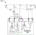
图1示出了根据一个示例性实施例的快充充电器1000的示意性电路图。Fig. 1 shows a schematic circuit diagram of a
如图1所示,快充充电器1000主要由PWM控制器100和快充协议芯片200以及外围电路构成。PWM控制器100、快充协议芯片200以及外围电路可以是任意类型的快充充电器中的PWM控制器、快充协议芯片以及外围电路,因此本文中不对其进行详细描述。As shown in FIG. 1 , a
通常,快充充电器1000是通过将快充协议芯片200组装于PWM控制器100和外围电路而形成的。因此,为了确保快充充电器的输出电压和输出电流满足精度要求,通常在生产快充协议芯片时,需要对其进行测试以确保其各个内部参数满足相应的精度要求,然后在快充协议芯片被组装到快充充电器之后,需要再次进行测试,以确保组装后的快充充电器的输出电压和输出电流满足相应的精度要求。Generally, the
以下参照图1和图2描述检测输出电压和输出电流是否满足精度要求的示例方式。An example manner of detecting whether the output voltage and the output current meet the accuracy requirements is described below with reference to FIGS. 1 and 2 .
图2示出了根据一个示例性实施例的图1的快充充电器的示意性局部电路图。Fig. 2 shows a schematic partial circuit diagram of the fast charging charger of Fig. 1 according to an exemplary embodiment.
参照图2,运算放大器CV_EA的正输入端子和负输入端子处的电压Vref_cv为用于产生快充充电器的输出电压的基准电压。运算放大器CC_EA的正输入端子和负输入端子处的电压Vref_cc对应于用于产生快充充电器的输出电流的基准电流。模数转换器ADC用于读取输出电压的电压回流值和输出电流的电流回流值。电压Vref_adc对应于模数转换器ADC的最大读取电压,其通常通过多个二进制位(bit)来表示。Referring to FIG. 2 , the voltage Vref_cv at the positive and negative input terminals of the operational amplifier CV_EA is a reference voltage for generating the output voltage of the fast charge charger. The voltage Vref_cc at the positive and negative input terminals of the operational amplifier CC_EA corresponds to the reference current used to generate the output current of the fast charge charger. The analog-to-digital converter ADC is used to read the voltage return value of the output voltage and the current return value of the output current. The voltage Vref_adc corresponds to the maximum read voltage of the analog-to-digital converter ADC, which is usually represented by a plurality of binary bits (bits).
在设置了预定的基准电压Vref_cv时,理论的输出电压Vin(节点VIN处的电压)可以由以下等式(1)来表示:When a predetermined reference voltage Vref_cv is set, the theoretical output voltage Vin (the voltage at the node VIN) can be expressed by the following equation (1):
Vin=Vref_cv×Kdiv (1)Vin=Vref_cv×Kdiv (1)
其中,Kdiv=(R1+R2)/R2,其中,R1和R2分别表示电阻器R1的电阻值和电阻器R2的电阻值。Wherein, Kdiv=(R1+R2)/R2, wherein R1 and R2 represent the resistance value of the resistor R1 and the resistance value of the resistor R2 respectively.
在快充充电器内读取的理论电压回读值Vin_adc可以由以下等式(2)来表示:The theoretical voltage readback value Vin_adc read in the fast charge charger can be expressed by the following equation (2):

其中,Vin_real表示节点VIN处的实际电压值,adc_bits表示模数转换器ADC的用于表示最大读取电压Vref_adc二进制位的位数,例如adc_bits=10。Wherein, Vin_real represents the actual voltage value at the node VIN, and adc_bits represents the number of bits of the analog-to-digital converter ADC used to represent the binary bits of the maximum read voltage Vref_adc, for example, adc_bits=10.
在设置了与预定基准电流对应的Vref_cc时,理论的输出电流Io(流过电阻器Ro或电流检测电阻器Rcs的电流)可以由以下等式(3)来表示:When Vref_cc corresponding to a predetermined reference current is set, the theoretical output current Io (the current flowing through the resistor Ro or the current sense resistor Rcs) can be expressed by the following equation (3):

其中,Ka表示运算放大器Ka的放大倍数,Rcs表示电流检测电阻器Rcs的电阻值,Vos表示运算放大器Ka的失调电压。Among them, Ka represents the magnification of the operational amplifier Ka, Rcs represents the resistance value of the current detection resistor Rcs, and Vos represents the offset voltage of the operational amplifier Ka.
在快充充电器内读取的理论电流回读值Io_adc可以由以下等式(4)来表示:The theoretical current readback value Io_adc read in the fast charge charger can be expressed by the following equation (4):

其中,Io_real表示实际流过电阻器Ro或电流检测电阻器Rcs的电流。Among them, Io_real represents the current that actually flows through the resistor Ro or the current detection resistor Rcs.
由以上等式(1)和等式(2)可以看出,理论电压值和电压回读值不涉及快充协议芯片200外部的参数。因此,通常可通过使得快充协议芯片200中的各参数在各自的精度范围内,来使得组装该芯片后的快充充电器的输出电压满足表1所示的电压精度要求。It can be seen from the above equations (1) and (2) that the theoretical voltage value and the voltage readback value do not involve external parameters of the fast
而理论电流值和电流回读值由于如等式(3)和等式(4)所示地涉及快充协议芯片200外部的参数(例如,Rcs),因此除了在生产快充协议芯片200时需要确保以上等式(3)和等式(4)所涉及的芯片内部的各参数处于各自的精度范围内之外,在快充协议芯片200被组装到快充充电器中之后,还需要进一步对组装后的快充充电器进行测试,以确保其输出电流满足表2所示的电流精度要求。The theoretical current value and the current readback value are related to the external parameters (for example, Rcs) of the fast
因此,这种确定电流精度的方式非常复杂,且仅能够确定快充充电器输出的电流处于表2所示的精度要求范围内,而无法提高快充充电器的实际输出电流的精确度,即无法对实际的输出电流进行校准。Therefore, this method of determining the current accuracy is very complicated, and it can only determine that the output current of the fast charge charger is within the range of accuracy requirements shown in Table 2, but cannot improve the accuracy of the actual output current of the fast charge charger, that is, The actual output current cannot be calibrated.
为此,根据本发明的示例性实施例提供了一种用于快充充电器的校准输出电流的方法。To this end, an exemplary embodiment of the present invention provides a method for calibrating an output current of a fast-charge charger.
图3示出了根据本发明的一个示例性实施例的用于快充充电器的校准输出电流的方法的流程图。这里的快充充电器可以是如图1或图2所示的任意快充充电器。Fig. 3 shows a flow chart of a method for calibrating output current of a fast charging charger according to an exemplary embodiment of the present invention. The fast charging charger here can be any fast charging charger as shown in FIG. 1 or FIG. 2 .
如图3所示,在步骤S110,获取用于校准输出电流的指示。As shown in FIG. 3 , in step S110 , an instruction for calibrating the output current is obtained.
在一个实施例中,步骤S110可包括:响应于检测到连接到测试设备,而获取到该指示。In one embodiment, step S110 may include: obtaining the indication in response to detecting the connection to the test device.
在另一个实施例中,步骤S110可包括:响应于从测试设备接收到用于对输出电流进行校准的校准命令,而获取到该指示。In another embodiment, step S110 may include: obtaining the indication in response to receiving a calibration command for calibrating the output current from the testing device.
快充充电设备与测试设备的连接可如图4所示。图4是示出了根据本发明的一个示例性实施例的快充充电器1000与测试设备2000之间的连接的示意图。The connection between the fast charging device and the test device can be shown in Figure 4. FIG. 4 is a schematic diagram showing the connection between the
如图4所示,在一个实施例中,测试设备2000可包括:快充测试治具300以及生产流程自动测试装置(ATE)400。As shown in FIG. 4 , in one embodiment, the
快充测试治具300可被配置为连接(例如,通过USB连接)在快充充电器1000和ATE400之间,并且包括电子负载310。电子负载310可充当用于连接到快充充电器1000的移动电子设备。The fast
返回参照图3,在步骤S120,响应于步骤S110的指示,生成具有预定电流值的预定输出电流。Referring back to FIG. 3 , in step S120 , in response to the instruction of step S110 , a predetermined output current having a predetermined current value is generated.
在步骤S110响应于检测到连接到测试设备而获取到指示的实施例中,该预定电流值可以为预先设置的用于对输出电流进行校准的电流值,例如,该预定电流值可被预先存储在快充充电器1000和测试设备2000内。In the embodiment in which the indication is obtained in response to the detection of the connection to the test device in step S110, the predetermined current value may be a preset current value for calibrating the output current, for example, the predetermined current value may be stored in advance Inside the
在步骤S110响应于从测试设备接收到用于对输出电流进行校准的校准命令而获取到指示的实施例中,校准命令可包括该预定电流值,即,测试设备2000可以向快充充电器1000指示需要产生多大的输出电流。In the embodiment in which the indication is obtained in step S110 in response to receiving a calibration command for calibrating the output current from the test device, the calibration command may include the predetermined current value, that is, the
在一个实施例中,生成以上预定输出电流的步骤S120可包括:响应于步骤S100获取的指示,生成电流值连续变化的多个输出电流(图5的步骤S121);以及接收中断信息,并将接收到中断信息时生成的输出电流确定为预定输出电流(图5的步骤S122)。In one embodiment, the step S120 of generating the above predetermined output current may include: in response to the indication obtained in step S100, generating a plurality of output currents with continuously changing current values (step S121 in FIG. 5 ); and receiving interrupt information, and The output current generated when the interruption information is received is determined as the predetermined output current (step S122 of FIG. 5 ).
作为一个示例,可通过调节基准电流(Vef_cc)而生成电流值从额定最大值连续减小的多个输出电流,在依次生成该多个输出电流的过程中,一旦接收到中断信息,则可确定快充充电器此时实际生成了具有预定电流值的预定输出电流。As an example, multiple output currents whose current values continuously decrease from the rated maximum value can be generated by adjusting the reference current (Vef_cc). In the process of sequentially generating the multiple output currents, once an interrupt message is received, it can be determined that At this time, the fast charge charger actually generates a predetermined output current with a predetermined current value.
作为一个示例,图4所示的电子负载310可响应于(预先存储的或ATE指示的)预定输出电流而生成中断信息(例如,宕机信号)。ATE400可检测该中断信息,并将该中断信息发送到快充充电器1000以指示其生成了该预定输出电流。As an example, the
返回参照图3,在步骤S130,确定用于生成预定输出电流的实际内部电流参数。Referring back to FIG. 3 , in step S130 , actual internal current parameters for generating a predetermined output current are determined.
这里,内部电流参数例如可包括快充充电器在生成输出电流时需要在其内部设置的相应基准电流(例如,Vef_cc)以及相应的电流回读值。实际内部参数可以是在接收到中断信息时实际设置的实际内部电流参数(以下将参照图5进行进一步描述)。Here, the internal current parameters may include, for example, a corresponding reference current (for example, Vef_cc) and a corresponding current readback value that the fast charge charger needs to set internally when generating an output current. The actual internal parameter may be an actual internal current parameter actually set when receiving the interrupt information (further description will be made below with reference to FIG. 5 ).
在步骤S140,确定预定输出电流与实际内部电流参数之间的关联,以在后续生成输出电流时,根据该关联来确定应设置的内部电流参数。In step S140, the correlation between the predetermined output current and the actual internal current parameter is determined, so that when the output current is subsequently generated, the internal current parameter that should be set is determined according to the correlation.
在一个实施例中,在步骤S140中可确定预定输出电流与实际内部电流参数之间比值,以在后续生成输出电流时,根据该比值来确定应设置的内部电流参数。In one embodiment, the ratio between the predetermined output current and the actual internal current parameter may be determined in step S140, so that the internal current parameter that should be set is determined according to the ratio when the output current is subsequently generated.
例如,该实际输出的预定输出电流为3A的电流,而实际设置的内部电流参数、例如基准电流值可能是理论上用于生成3.1A的输出电流的值,在这种情况下,可通过获得该预定输出电流与实际基准电流值之间的比值(3/3.1),来在后续需要输出某个输出电流时,通过该比值来确定需要设置的基准电流值。应该理解,以上电流值的数值仅是示例,电流值可基于实际设计方案而具有任意不同的值。For example, the predetermined output current of the actual output is a current of 3A, while the actually set internal current parameters, such as the reference current value, may be theoretically used to generate an output current of 3.1A. In this case, it can be obtained by obtaining The ratio (3/3.1) between the predetermined output current and the actual reference current value is used to determine the reference current value to be set when a certain output current needs to be output subsequently. It should be understood that the above numerical values of the current values are only examples, and the current values may have any different values based on actual design schemes.
根据本发明的以上示例性实施例的用于快充充电器的校准输出电流的方法,能够利用在快充充电器生成预定输出电流时的实际内部电流参数,来获得输出电流与应设置的内部电流参数之间的关联,从而能够校准实际的输出电流,提高输出电流的精确度。According to the method for calibrating the output current of the fast charging charger according to the above exemplary embodiments of the present invention, the actual internal current parameters when the fast charging charger generates a predetermined output current can be used to obtain the output current and the internal current that should be set. The correlation between the current parameters, so that the actual output current can be calibrated, and the accuracy of the output current can be improved.
图5示出了根据本发明的另一示例性实施例的用于快充充电器的校准输出电流的方法的流程图。FIG. 5 shows a flow chart of a method for calibrating output current of a fast charging charger according to another exemplary embodiment of the present invention.
参照图5和图3,图5中的步骤S110和步骤S140与图3相同,不同之处在于:图5通过步骤S121和步骤S122示出了步骤S120的一个示例,并通过步骤S131-S134示出了步骤S130的一个示例。以上已经参照图3描述了步骤S121和步骤S122,这里不再赘述。5 and FIG. 3, step S110 and step S140 in FIG. 5 are the same as in FIG. An example of step S130 is shown. Step S121 and step S122 have been described above with reference to FIG. 3 , and will not be repeated here.
在步骤S131,可确定在步骤S122中接收到中断信息时的实际电流回读值,该实际电流回读值可以为实际读取到的电流回读值(例如,通过图2所示的数模转换器ADC读取到的电流回读值)。In step S131, the actual current readback value when the interrupt information is received in step S122 can be determined, and the actual current readback value can be the actually read current readback value (for example, through the digital-analog The current readback value read by the converter ADC).
在步骤S132,可确定预定输出电流的理论电流回读值,该理论电流回读值可以为理论上与该预定输出电流应对应的电流回读值(例如,通过将预定输出电流的电流值作为Io_real代入到以上等式(4)中而得出的电流回读值)。In step S132, the theoretical current readback value of the predetermined output current can be determined, and the theoretical current readback value can be the current readback value theoretically corresponding to the predetermined output current (for example, by taking the current value of the predetermined output current as Substituting Io_real into Equation (4) above yields the current readback value).
在步骤S133,可确定接收到中断信息时的实际基准电流,该实际基准电流可以为实际上用于生成预定输出电流的基准电流(例如,实际上设置的Vref_cc值)。In step S133, the actual reference current when the interruption information is received may be determined, which may be the reference current actually used to generate the predetermined output current (eg, the actually set Vref_cc value).
在步骤S134,可确定预定输出电流的理论基准电流,该理论基准电流为理论上生成预定输出电流应设置的基准电流(例如,理论上由以上等式(3)得出的生成预定输出电流所应设置的Vref_cc值)。In step S134, the theoretical reference current of the predetermined output current can be determined, and the theoretical reference current is the reference current that should be set to generate the predetermined output current in theory (for example, theoretically obtained by the above equation (3) to generate the predetermined output current. The Vref_cc value that should be set).
在这种情况下,在一个实施例中,步骤S140可包括:确定实际电流回读值与理论电流回读值之间的第一关联;确定实际基准电流与理论基准电流之间的第二关联。In this case, in one embodiment, step S140 may include: determining a first correlation between the actual current readback value and the theoretical current readback value; determining a second correlation between the actual reference current and the theoretical reference current .
在这种情况下,第一关联可用于在后续生成输出电流时确定应对应读取到的电流回读值(Io_adc_real),以上第二关联可用于在后续生成输出电流时确定应设置的基准电流(例如,Vref_cc值)。In this case, the first association can be used to determine the current readback value (Io_adc_real) that should be read when the output current is subsequently generated, and the above second association can be used to determine the reference current that should be set when the output current is subsequently generated (for example, Vref_cc value).
在一个实施例中,第一关联可以为实际电流回读值与理论电流回读值之间的比值(K1),第二关联可以为实际基准电流与理论基准电流之间的比值(K2)。In one embodiment, the first correlation may be the ratio (K1) between the actual current readback value and the theoretical current readback value, and the second correlation may be the ratio (K2) between the actual reference current and the theoretical reference current.
在这种情况下,比值K1可以被视为将实际电流回读值与等式(4)相关联并简化为y=k1x+b1函数的形式后的k1值(x为自变量,y为因变量,k1和b1为常数)。原因如下:In this case, the ratio K1 can be regarded as the value of k 1 after relating the actual current readback value to equation( 4) and simplifying it to the form of y=k1 x+b1 function (x is the independent variable , y is the dependent variable, k1 and b1 are constants). The reasons are as follows:
参照表2所示的对快充充电器的输出电流的精度要求,尤其在电流大于0.5A的重载电流范围内,以上k1值对电流精度的影响远远大于b1值对对电流精度的影响。例如,在输出功率为80W、输出电流为8A的快充充电器的示例中,k1值对电流精度的影响约为b1值对电流精度的影响的200倍以上。因此,可以通过确定以上比值K1(即,k1值)来在后续生成输出电流时校准应对应读取到的电流回读值。Referring to the accuracy requirements for the output current of the fast charging charger shown in Table 2, especially in the heavy-load current range with a current greater than 0.5A, the influence of the above k1 value on the current accuracy is far greater than that of the b1 value on the current accuracy Impact. For example, in the example of a fast-charge charger with an output power of 80W and an output current of 8A, the influence of the value ofk1 on the current accuracy is about 200 times more than that of the value ofb1 on the current accuracy. Therefore, by determining the above ratio K1 (ie, the value of k1 ), the current readback value that should be read correspondingly can be calibrated when the output current is subsequently generated.
此外,比值K2可以被视为将实际基准电流与等式(3)关联并简化为y=k2x+b2函数的形式后的k2值(x为自变量,y为因变量,k2和b2为常数)。原因如下:In addition, the ratio K2 can be regarded as thek2 value after relating the actual reference current to equation (3) and simplifying it to the form of y=k2x +b2 function (x is the independent variable, y is the dependent variable, k2 and b2 are constants). The reasons are as follows:
参照表2所示的对快充充电器的输出电流的精度要求,尤其在电流大于0.5A的重载电流范围内,以上k2值对电流精度的影响远远大于b2值对电流精度的影响。例如,在输出功率为80W、输出电流为8A的快充充电器的示例中,k2值对电流精度的影响约为b2值对电流精度的影响的10倍以上。因此,可以通过确定以上比值K2(即,k2值)来在后续生成输出电流时确定应设置的基准电流(例如,Vref_cc值)、即校准输出电流,从而使得输出电流更精确。Referring to the accuracy requirements for the output current of the fast charging charger shown in Table 2, especially in the heavy-load current range with a current greater than 0.5A, the influence of the above k2 value on the current accuracy is far greater than that of the b2 value on the current accuracy Influence. For example, in the example of a fast-charge charger with an output power of 80W and an output current of 8A, the effect of thek2 value on the current accuracy is about 10 times more than the effect of theb2 value on the current accuracy. Therefore, the reference current (for example, Vref_cc value) that should be set when the output current is subsequently generated can be determined by determining the above ratio K2 (ie, the value of k2 ), that is, the output current is calibrated, so that the output current is more accurate.
由于重载电流范围内的电流精度要求更高,因此在一个实施例中,可将针对预定输出电流的预定电流值设置为大于预定阈值且小于或等于额定最大电流值的电流值,该预定阈值可以为用于区分快充充电器的轻载电流与重载电流的阈值(例如,以上表2中的0.5A)。Since the current accuracy in the heavy load current range is required to be higher, in one embodiment, the predetermined current value for the predetermined output current can be set to a current value greater than the predetermined threshold and less than or equal to the rated maximum current value, the predetermined threshold It may be a threshold for distinguishing the light load current and the heavy load current of the fast charging charger (for example, 0.5A in the above Table 2).
通过以上方式,可以通过对处于重载电流范围内的预定输出电流的单次采样,而获得对后续输出电流进行校准的校准系数K1和K2,从而能够非常简便地获得高精度的输出电流。此外,由于轻载范围内的输出电流的精度要求相对宽松,因此以上获得的校准系数K1和K2同样适用于对轻载范围内的输出电流进行校准。Through the above method, the calibration coefficients K1 and K2 for calibrating the subsequent output current can be obtained through a single sampling of the predetermined output current within the heavy-load current range, so that the high-precision output current can be obtained very simply. In addition, since the accuracy requirements of the output current in the light load range are relatively loose, the calibration coefficients K1 and K2 obtained above are also applicable to the calibration of the output current in the light load range.
此外,通过以上方式,可省略在图1和图2所示的快充协议芯片200的生产过程中对快充协议芯片内部相关参数的检测,仅通过在快充协议芯片被组装到快充充电器后的单次输出电流采样,即可实现对输出电流的校准,从而极大地节省了芯片生产过程中的测试开销。In addition, through the above method, the detection of relevant parameters inside the fast charging protocol chip can be omitted during the production process of the fast
此外,为了进一步精确地校准输出电流,可以通过产生两个预定输出电流来生成各自相应的实际电流回读值、理论电流回读值、实际基准电流、以及理论基准电流,从而在步骤S140中通过解方程的方式确定出以上y=k1x+b1函数、y=k2x+b2函数中的k1、b1、k2、b2,从而使得校准后的输出电流更精确。图6示出了这样的一个示例。In addition, in order to further accurately calibrate the output current, two predetermined output currents can be generated to generate respective corresponding actual current readback values, theoretical current readback values, actual reference currents, and theoretical reference currents, so that in step S140 by The method of solving the equation determines k1 , b1 , k 2 , and b 2 in the above y=k1 x+b1 function and y=k2x +b 2function , so that the calibrated output current is more accurate. Figure 6 shows such an example.
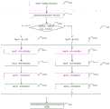
图6示出了根据本发明的另一示例性实施例的用于快充充电器的校准输出电流的方法的流程图。FIG. 6 shows a flowchart of a method for calibrating output current of a fast-charge charger according to another exemplary embodiment of the present invention.
如图6所示,图6的步骤S110可以与图3和图5中的步骤S110相同。而图6的步骤S120用于生成具有不同的预定电流值的两个输出电流。即,预定电流值可包括第一电流值和第二电流值。预定输出电流可包括:与第一电流值对应的第一输出电流、以及与第二电流值对应的第二输出电流。所接收的中断信息可包括:与所述第一输出电流对应的第一中断信息、以及与所述第二输出电流对应的第二中断信息。As shown in FIG. 6 , step S110 in FIG. 6 may be the same as step S110 in FIG. 3 and FIG. 5 . And step S120 of FIG. 6 is used to generate two output currents with different predetermined current values. That is, the predetermined current value may include a first current value and a second current value. The predetermined output current may include: a first output current corresponding to the first current value, and a second output current corresponding to the second current value. The received interruption information may include: first interruption information corresponding to the first output current, and second interruption information corresponding to the second output current.
例如,在步骤S121,可如以上参照图3所述的方式生成电流值连续变化的多个输出电流。For example, in step S121 , a plurality of output currents whose current values continuously change may be generated in the manner described above with reference to FIG. 3 .
在执行步骤S121的过程中,可执行步骤S122-1,确定是否接收到第一中断信息或第二中断信息。During the execution of step S121, step S122-1 may be executed to determine whether the first interruption information or the second interruption information is received.
在接收到第一中断信息的情况下,可执行步骤S122-2,确定此时生成的输出电流为第一输出电流。When the first interrupt information is received, step S122-2 may be executed to determine that the output current generated at this time is the first output current.
在接收到第二中断信息的情况下,可执行步骤S122-3,确定此时生成的输出电流为第二输出电流。When the second interruption information is received, step S122-3 may be executed to determine that the output current generated at this time is the second output current.
在步骤S120生成了两个输出电流的情况下,在步骤S130中确定的实际电流回读值可包括:与第一中断信息对应的第一实际电流回读值、以及与第二中断信息对应的第二实际电流回读值。在步骤S130中确定的理论电流回读值可包括:与第一输出电流对应的第一理论电流回读值、以及与第二输出电流对应的第二理论电流回读值。在步骤S130中确定的实际基准电流可包括:与第一中断信息对应的第一实际基准电流、以及与第二中断信息对应的第二实际基准电流。在步骤S130中确定的理论基准电流可包括:与第一输出电流对应的第一理论基准电流、以及与第二输出电流对应的第二理论基准电流。In the case that two output currents are generated in step S120, the actual current readback value determined in step S130 may include: the first actual current readback value corresponding to the first interrupt information, and the second actual current readback value corresponding to the second interrupt information The second actual current readback value. The theoretical current readback value determined in step S130 may include: a first theoretical current readback value corresponding to the first output current, and a second theoretical current readback value corresponding to the second output current. The actual reference current determined in step S130 may include: a first actual reference current corresponding to the first interruption information, and a second actual reference current corresponding to the second interruption information. The theoretical reference current determined in step S130 may include: a first theoretical reference current corresponding to the first output current, and a second theoretical reference current corresponding to the second output current.
例如,在步骤S131-1,可确定与第一中断信息对应的第一实际电流回读值。在步骤S132-1,可确定与第一输出电流对应的第一理论电流回读值。在步骤S133-1,可确定与第一中断信息对应的第一实际基准电流。在步骤S134-1,可确定与第一输出电流对应的第一理论基准电流。For example, in step S131-1, the first actual current readback value corresponding to the first interruption information may be determined. In step S132-1, a first theoretical current readback value corresponding to the first output current may be determined. In step S133-1, a first actual reference current corresponding to the first interruption information may be determined. In step S134-1, a first theoretical reference current corresponding to the first output current may be determined.
在步骤S131-2,可确定与第二中断信息对应的第二实际电流回读值。在步骤S132-2,可确定与第二输出电流对应的第二理论电流回读值。在步骤S132-3,可确定与第二中断信息对应的第二实际基准电流。在步骤S132-4,可确定与第二输出电流对应的第二理论基准电流。In step S131-2, a second actual current readback value corresponding to the second interruption information may be determined. In step S132-2, a second theoretical current readback value corresponding to the second output current may be determined. In step S132-3, a second actual reference current corresponding to the second interruption information may be determined. In step S132-4, a second theoretical reference current corresponding to the second output current may be determined.
相应地,在步骤S140,可基于第一实际电流回读值、第二实际电流回读值、第一理论电流回读值、以及第二理论电流回读值而确定实际电流回读值相对于理论电流回读值的函数(即,以上第一关联,例如以上y=k1x+b1的k1值和b1值)。此外,在步骤S140,可基于第一实际基准电流、第二实际基准电流、第一理论基准电流、以及第二理论基准电流而确定实际基准电流相对于理论基准电流的函数(即,以上第二关联,例如以上y=k2x+b2的k2值和b2值)。Correspondingly, in step S140, it may be determined based on the first actual current readback value, the second actual current readback value, the first theoretical current readback value, and the second theoretical current readback value to determine the relative A function of the theoretical current readback value (ie, the first correlation above, such as the k1 and b1 values of y=k1 x+b1 above). In addition, in step S140, a function of the actual reference current relative to the theoretical reference current may be determined based on the first actual reference current, the second actual reference current, the first theoretical reference current, and the second theoretical reference current (ie, the above second Correlation, such as the above k2 value and b2 value of y=k2 x+b2 ).
这种情况下,以上第一电流值和以上第二电流值可以为快充充电器的额定最小电流值与额定最大电流值之间的任意两个不同的电流值。In this case, the above first current value and the above second current value may be any two different current values between the rated minimum current value and the rated maximum current value of the fast charging charger.
通过以上方式,由于可获得以上y=k1x+b1的k1值和b1值以及y=k2x+b2的k2值和b2值,因而可以更加精准地校准快充充电器的准输出电流,从而使得输出电流更匹配负载(移动电子设备)所需的电流。Through the above method, since the above k 1 value and b1 value of y=k1 x+b1 and the k2 value andb 2value of y=k2 x+b2 can be obtained, the fast charging can be calibrated more accurately The quasi-output current of the charger makes the output current more closely match the current required by the load (mobile electronic device).
图7示出了根据本发明的另一示例性实施例的用于快充充电器的校准输出电流的装置700的框图。Fig. 7 shows a block diagram of an
根据本发明的示例性实施例的用于快充充电器的校准输出电流的装置700包括第一单元710、第二单元720、第三单元730和第四单元740。The
第一单元710被配置为获取用于校准输出电流的指示。The first unit 710 is configured to obtain an indication for calibrating the output current.
第二单元720被配置为响应于该指示,生成具有预定电流值的预定输出电流。The
第三单元730被配置为确定用于生成预定输出电流的实际内部电流参数。The
第四单元740被配置为确定预定输出电流与实际内部电流参数之间的关联,以在后续生成输出电流时,根据该关联来确定应设置的内部电流参数。The
以上已经参照图3至图6详细描述了获取指示、生成预定输出电流、确定内部电流参数、以及确定以上关联的过程的示例,这里不再赘述。换言之,根据本发明的示例性实施例的用于快充充电器的校准输出电流的装置700可以执行以上参照图3至图6描述的方法中的任意步骤/操作。The examples of the process of obtaining the indication, generating the predetermined output current, determining the internal current parameter, and determining the above association have been described in detail above with reference to FIGS. 3 to 6 , and will not be repeated here. In other words, the
根据本发明的示例性实施例的用于快充充电器的校准输出电流的装置,能够利用在快充充电器生成预定输出电流时的实际内部电流参数,来获得输出电流与应设置的内部电流参数之间的关联,从而能够校准实际的输出电流,提高输出电流的精确度。According to the device for calibrating the output current of a fast charging charger according to an exemplary embodiment of the present invention, the actual internal current parameters when the fast charging charger generates a predetermined output current can be used to obtain the output current and the internal current that should be set. The correlation between parameters can calibrate the actual output current and improve the accuracy of the output current.
根据本公开的实施例还提供一种存储有指令的计算机可读介质,该指令在由处理器执行时可使得处理器执行以上根据本公开的实施例的用于快充充电器的校准输出电流的方法。According to an embodiment of the present disclosure, there is also provided a computer-readable medium storing instructions, which, when executed by a processor, can cause the processor to perform the above calibration output current for a fast charging charger according to an embodiment of the present disclosure. Methods.
应该理解,本公开并不局限于上文所描述并在图中示出的特定配置和处理。为了简明起见,这里省略了对已知方法的详细描述。在上述实施例中,描述和示出了若干具体的步骤作为示例。但是,本发明的方法过程并不限于所描述和示出的具体步骤,本领域的技术人员可以在领会本发明的精神后,作出各种改变、修改和添加,或者改变步骤之间的顺序。It should be understood that the present disclosure is not limited to the specific configurations and processes described above and shown in the drawings. For conciseness, detailed descriptions of known methods are omitted here. In the above embodiments, several specific steps are described and shown as examples. However, the method process of the present invention is not limited to the specific steps described and shown, and those skilled in the art can make various changes, modifications and additions, or change the sequence of steps after understanding the spirit of the present invention.
以上所述的结构框图中所示的功能块可以实现为硬件、软件、固件或者它们的组合。当以硬件方式实现时,其可以例如是电子电路、专用集成电路(ASIC)、适当的固件、插件、功能卡等。当以软件方式实现时,本发明的元素是被用于执行所需任务的程序或者代码段。程序或者代码段可以存储在机器可读介质中,或者通过载波中携带的数据信号在传输介质或者通信链路上传送。“机器可读介质”可以包括能够存储或传输信息的任何介质。机器可读介质的示例包括电子电路、半导体存储器设备、ROM、闪存、可擦除ROM(EROM)、软盘、CD-ROM、光盘、硬盘、光纤介质、射频(RF)链路等。代码段可以经由诸如因特网、内联网等的计算机网络被下载。The functional blocks shown in the structural block diagrams described above may be implemented as hardware, software, firmware, or a combination thereof. When implemented in hardware, it may be, for example, an electronic circuit, an application specific integrated circuit (ASIC), suitable firmware, a plug-in, a function card, or the like. When implemented in software, the elements of the invention are the programs or code segments employed to perform the required tasks. Programs or code segments can be stored in machine-readable media, or transmitted over transmission media or communication links by data signals carried in carrier waves. "Machine-readable medium" may include any medium that can store or transmit information. Examples of machine-readable media include electronic circuits, semiconductor memory devices, ROM, flash memory, erasable ROM (EROM), floppy disks, CD-ROMs, optical disks, hard disks, fiber optic media, radio frequency (RF) links, and the like. Code segments may be downloaded via a computer network such as the Internet, an Intranet, or the like.
本发明可以以其他的具体形式实现,而不脱离其精神和本质特征。例如,特定实施例中所描述的算法可以被修改,而系统体系结构并不脱离本发明的基本精神。因此,当前的实施例在所有方面都被看作是示例性的而非限定性的,本发明的范围由所附权利要求而非上述描述定义,并且,落入权利要求的含义和等同物的范围内的全部改变从而都被包括在本发明的范围之中。The present invention may be embodied in other specific forms without departing from its spirit and essential characteristics. For example, the algorithms described in certain embodiments may be modified without departing from the basic spirit of the invention in terms of system architecture. Therefore, the present embodiments are to be considered in all respects as illustrative rather than restrictive, the scope of the present invention is defined by the appended claims rather than the above description, and, within the meaning and equivalents of the claims, All changes in scope are thereby embraced within the scope of the invention.
Claims (15)
Translated fromChinesePriority Applications (2)
| Application Number | Priority Date | Filing Date | Title |
|---|---|---|---|
| CN202211581283.4ACN115776160A (en) | 2022-12-09 | 2022-12-09 | Method and apparatus for calibrating output current for fast charger |
| TW112104153ATWI845152B (en) | 2022-12-09 | 2023-02-06 | Method and device for calibrating output current of fast charging charger and computer-readable medium storing instructions used therein |
Applications Claiming Priority (1)
| Application Number | Priority Date | Filing Date | Title |
|---|---|---|---|
| CN202211581283.4ACN115776160A (en) | 2022-12-09 | 2022-12-09 | Method and apparatus for calibrating output current for fast charger |
Publications (1)
| Publication Number | Publication Date |
|---|---|
| CN115776160Atrue CN115776160A (en) | 2023-03-10 |
Family
ID=85392139
Family Applications (1)
| Application Number | Title | Priority Date | Filing Date |
|---|---|---|---|
| CN202211581283.4APendingCN115776160A (en) | 2022-12-09 | 2022-12-09 | Method and apparatus for calibrating output current for fast charger |
Country Status (2)
| Country | Link |
|---|---|
| CN (1) | CN115776160A (en) |
| TW (1) | TWI845152B (en) |
Family Cites Families (4)
| Publication number | Priority date | Publication date | Assignee | Title |
|---|---|---|---|---|
| HUE042719T2 (en)* | 2016-01-05 | 2019-07-29 | Guangdong Oppo Mobile Telecommunications Corp Ltd | Rapid charging method, mobile terminal and adapter |
| EP3282550B1 (en)* | 2016-02-05 | 2020-04-15 | Guangdong Oppo Mobile Telecommunications Corp., Ltd. | Adapter and charging control method |
| CN107231013B (en)* | 2016-05-24 | 2019-01-15 | 华为技术有限公司 | A kind of method of charging, terminal, charger and system |
| CN115425711B (en)* | 2022-09-09 | 2024-10-01 | Oppo广东移动通信有限公司 | Method, device, terminal equipment and storage medium for obtaining charging current |
- 2022
- 2022-12-09CNCN202211581283.4Apatent/CN115776160A/enactivePending
- 2023
- 2023-02-06TWTW112104153Apatent/TWI845152B/enactive
Also Published As
| Publication number | Publication date |
|---|---|
| TWI845152B (en) | 2024-06-11 |
| TW202425480A (en) | 2024-06-16 |
Similar Documents
| Publication | Publication Date | Title |
|---|---|---|
| US10823784B2 (en) | Current detection system, method and device | |
| US8193834B2 (en) | Multiple detection circuit for accessory jacks | |
| CN102074766B (en) | Battery pack and method of sensing voltage of the battery pack | |
| US8970165B2 (en) | Determination circuit | |
| US8324861B2 (en) | Multi-channel converter with self-diagnosis functionality | |
| WO2021196684A1 (en) | Method and apparatus for estimating performance parameters of battery, device and medium | |
| CN109298657B (en) | A method of time-varying signal power detection and automatic gain control based on FPGA | |
| WO2023179255A1 (en) | Charging device and method, and related equipment | |
| CN105743163B (en) | Charger whether the detection method and adaptive charging method of standard configuration | |
| CN115616442A (en) | Detection device, inverter and detection method | |
| CN108475982A (en) | Switching power supply circuit and switching power supply current detection method | |
| CN218727796U (en) | Analog domain function verification circuit and function verification device of digital-analog hybrid chip | |
| CN113885968B (en) | Adaptive digital-analog mixed starting mode setting system and method | |
| CN115776160A (en) | Method and apparatus for calibrating output current for fast charger | |
| CN110676804B (en) | Detection circuit and switch module using same | |
| CN104168067A (en) | Method for judging optical power signal intensity in optical receiving circuit and circuit thereof | |
| CN115236481B (en) | High-precision current detection method and chip module thereof | |
| CN114337614B (en) | Comparator-based high-precision edge detection method and system | |
| TW202017321A (en) | Calibration method and calibration system | |
| CN116662356A (en) | Open-circuit voltmeter updating method, device, equipment and computer storage medium | |
| CN105048583A (en) | Battery charging method and circuit | |
| CN112865229A (en) | Charging protection circuit and wireless earphone | |
| CN117413186A (en) | Voltage sampling device and related method | |
| CN112757950B (en) | Charging pile and its electric vehicle voltage detection circuit and method | |
| US6064181A (en) | Method for detecting fully-charged state of rechargeable battery |
Legal Events
| Date | Code | Title | Description |
|---|---|---|---|
| PB01 | Publication | ||
| PB01 | Publication | ||
| SE01 | Entry into force of request for substantive examination | ||
| SE01 | Entry into force of request for substantive examination | ||
| CB02 | Change of applicant information | Country or region after:China Address after:201203 Shanghai Pudong New Area Zhangjiang High-tech Park, No. 168 Huatuo Road, Building 3 Commercial Center Applicant after:Angbao Integrated Circuit Co.,Ltd. Address before:201203 Shanghai Pudong New Area Zhangjiang High-tech Park, No. 168 Huatuo Road, Building 3 Commercial Center Applicant before:On-Bright Electronics (Shanghai) Co.,Ltd. Country or region before:China | |
| CB02 | Change of applicant information |