CN115770096A - Centrum expander and compression fracture centrum treatment external member - Google Patents
Centrum expander and compression fracture centrum treatment external memberDownload PDFInfo
- Publication number
- CN115770096A CN115770096ACN202211418619.5ACN202211418619ACN115770096ACN 115770096 ACN115770096 ACN 115770096ACN 202211418619 ACN202211418619 ACN 202211418619ACN 115770096 ACN115770096 ACN 115770096A
- Authority
- CN
- China
- Prior art keywords
- vertebral body
- supporting structure
- driving member
- expander
- flap
- Prior art date
- Legal status (The legal status is an assumption and is not a legal conclusion. Google has not performed a legal analysis and makes no representation as to the accuracy of the status listed.)
- Pending
Links
Images


Landscapes
- Prostheses (AREA)
Abstract
Translated fromChinese
Description
Translated fromChinese技术领域technical field
本申请属于医疗设备技术领域,更具体地说,是涉及一种椎体扩张器及压缩骨折椎体治疗套件。The application belongs to the technical field of medical equipment, and more specifically relates to a vertebral body expander and a treatment kit for compressing fractured vertebral bodies.
背景技术Background technique
随着当前人口老龄化的加剧,骨质疏松症的发病率正在逐年增高,而椎体压缩性骨折作为骨质疏松症最常见的并发症也正受到人们广泛的关注。椎体一旦发生骨折,超过80%的患者会出现持续的腰背痛及功能障碍,并将严重影响生活质量,加重生活负担;且对严重椎体压缩骨折患者,保守治疗往往具有较高的致残率和病死率,因此临床迫切需要一种安全有效的治疗手段。With the aging of the current population, the incidence of osteoporosis is increasing year by year, and vertebral compression fractures, as the most common complication of osteoporosis, are also attracting widespread attention. Once the vertebral body is fractured, more than 80% of the patients will experience persistent low back pain and dysfunction, which will seriously affect the quality of life and increase the burden of life; and for patients with severe vertebral compression fractures, conservative treatment often has a high risk of death. Therefore, there is an urgent clinical need for a safe and effective treatment.
目前应用于临床的椎体扩张方法根据椎体复位与固定特点可分为两大类。第一类:椎体复位与固定分步操作的撑开器,首先由撑开器扩张复位椎体再植入填充物强化固定椎体,其过程需穿刺建立工作通道,一定程度增加脊髓损伤风险,例如Kyphon球囊扩张、SKY骨扩张器等。第二类:椎体复位与固定一体化操作的撑开器,这类椎体扩张方法需要植入异物,往往对撑开器材料及形状设计有较高要求,还增加术后感染风险,例如Pillar椎体支柱块、Vessel-X骨材料填充系统等。The methods of vertebral body expansion currently used clinically can be divided into two categories according to the characteristics of vertebral body reduction and fixation. The first category: a spreader for vertebral body reduction and fixation in steps. First, the spreader expands and resets the vertebral body, and then implants fillers to strengthen and fix the vertebral body. The process requires puncture to establish a working channel, which increases the risk of spinal cord injury to a certain extent. , such as Kyphon balloon expansion, SKY bone expander, etc. The second category: a distractor that integrates vertebral body reduction and fixation. This type of vertebral body expansion method requires the implantation of foreign bodies, which often has higher requirements for the material and shape design of the distractor, and also increases the risk of postoperative infection, such as Pillar vertebral pillar block, Vessel-X bone material filling system, etc.
其中,临床上膨胀式球囊扩张器常应用于压缩骨折椎体的骨折复位,并在椎体松质骨内形成空腔,方便填充植入物。但是球囊由于其弹性较大,扩张方向难以控制,最终在椎体内形成的空腔形状无法预估和控制。在压缩性骨折的椎体内,球囊往往朝阻力较小的方向扩张,扩张方向不能保证与骨折需复位方向一致,有时甚至与骨折复位方向相背离,造成更严重的骨折移位,甚至压迫脊髓,产生神经损伤症状。当球囊内撑开压力过高时,还容易导致球囊破裂。Among them, the inflatable balloon dilator is often used clinically to compress the fracture reduction of the fractured vertebral body, and to form a cavity in the cancellous bone of the vertebral body, which is convenient for filling the implant. However, due to the high elasticity of the balloon, it is difficult to control the direction of expansion, and the final shape of the cavity formed in the vertebral body cannot be predicted and controlled. In vertebral bodies with compression fractures, the balloon tends to expand in the direction of less resistance, and the expansion direction cannot be guaranteed to be consistent with the direction of fracture reduction, and sometimes even deviates from the direction of fracture reduction, resulting in more serious fracture displacement and even compression Spinal cord, producing symptoms of nerve damage. When the expansion pressure in the balloon is too high, it is easy to cause the balloon to rupture.
发明内容Contents of the invention
本申请实施例的目的在于提供一种椎体扩张器及压缩骨折椎体治疗套件,以解决现有技术中存在的无法实现椎体内的定向扩张,椎体扩张效果欠佳的技术问题。The purpose of the embodiments of the present application is to provide a vertebral body expander and a treatment kit for compressing a fractured vertebral body, so as to solve the technical problems in the prior art that the directional expansion of the vertebral body cannot be realized and the effect of vertebral body expansion is not good.
为实现上述目的,本申请采用的技术方案是:In order to achieve the above object, the technical scheme adopted by the application is:
提供一种椎体扩张器,包括第一基体、连接于所述第一基体上的顶撑结构以及与所述顶撑结构驱动连接的驱动件,所述驱动件能够驱动所述顶撑结构向所述椎体扩张器的一侧撑开。Provided is a vertebral body expander, comprising a first base body, a supporting structure connected to the first base body, and a driving member drivingly connected with the supporting structure, and the driving member can drive the supporting structure to One side of the vertebral body expander is stretched.
作为上述技术方案的进一步改进:As a further improvement of the above technical solution:
可选的,所述第一基体具有驱动件操作腔,所述顶撑结构位于所述驱动件操作腔的长度方向的第一端,所述驱动件能够沿所述驱动件操作腔的长度方向可运动地安装于所述驱动件操作腔,所述驱动件沿所述驱动件操作腔运动至预定位置时,能够挤压所述顶撑结构向所述驱动件的运动方向的一侧撑开。Optionally, the first base has a driving element operating cavity, the supporting structure is located at the first end in the length direction of the driving element operating cavity, and the driving element can move along the length direction of the driving element operating cavity. It is movably installed in the operating chamber of the driving member, and when the driving member moves to a predetermined position along the operating chamber of the driving member, it can press the supporting structure to expand to one side of the moving direction of the driving member .
可选的,所述顶撑结构包括连接于所述第一基体上的固定瓣和撑开瓣,所述固定瓣的内壁和所述撑开瓣的内壁中,至少一者具有沿所述驱动件操作腔的长度方向倾斜的斜面,所述驱动件运动至与所述斜面接触时,能够挤压所述撑开瓣向所述驱动件的运动方向的一侧撑开。Optionally, the support structure includes a fixed petal and a stretch petal connected to the first base, at least one of the inner wall of the fixed petal and the inner wall of the stretch petal has a The longitudinal direction of the operating cavity of the driving member is inclined, and when the driving member moves to contact with the inclined surface, it can squeeze the expansion flap to expand to one side of the moving direction of the driving member.
可选的,所述撑开瓣可弹性弯曲地连接于所述第一基体上。Optionally, the expansion petals are connected to the first base in an elastically bendable manner.
可选的,所述驱动件为推杆,所述推杆与所述驱动件操作腔的内壁螺纹连接,所述推杆的第一端能够挤压所述撑开瓣的内壁向所述驱动件的运动方向的一侧撑开。Optionally, the driving part is a push rod, which is threadedly connected to the inner wall of the operating cavity of the driving part, and the first end of the pushing rod can press the inner wall of the expanding flap to the driving part. One side of the moving direction of the piece is braced.
可选的,还包括弹性套,所述弹性套包覆于所述顶撑结构的外侧。Optionally, an elastic sleeve is also included, and the elastic sleeve covers the outer side of the supporting structure.
可选的,还包括可拆卸地连接于所述第一基体上的持握件。Optionally, a holding member detachably connected to the first base is also included.
本申请还提供一种压缩骨折椎体治疗套件,包括上述的椎体扩张器。The present application also provides a treatment kit for compressing a fractured vertebral body, including the aforementioned vertebral body expander.
作为上述技术方案的进一步改进:As a further improvement of the above technical solution:
可选的,还包括植骨装置,所述植骨装置包括第二基体和植入件,所述第二基体具有导出口和植入件操作腔,所述植入件能够伸入至所述植入件操作腔。Optionally, a bone grafting device is also included, the bone grafting device includes a second base body and an implant, the second base body has an outlet and an implant operating cavity, and the implant can extend into the Implant operating cavity.
可选的,所述导出口的端面上设有固定齿。Optionally, fixed teeth are provided on the end surface of the outlet.
本申请提供的一种椎体扩张器及压缩骨折椎体治疗套件的有益效果在于:The beneficial effects of the vertebral body expander and the compression fractured vertebral body treatment kit provided by the application are:
本申请提供的一种椎体扩张器,包括第一基体、连接于第一基体上的顶撑结构以及与顶撑结构驱动连接的驱动件,驱动件能够驱动顶撑结构向椎体扩张器的一侧撑开。A vertebral body expander provided by the present application includes a first base body, a propping structure connected to the first base body, and a driving element drivingly connected with the propping structure, and the driving element can drive the propping structure toward the vertebral body expander. One side propped open.
其中,第一基体作为顶撑结构的安装基体,具体的,第一基体可以为杆件、管件、基座等。顶撑结构伸入至椎体待扩张复位的位置,顶撑结构在驱动件的驱动下,向椎体扩张器的一侧撑开,该侧即为顶撑结构的展开侧,以使顶撑结构能够沿指定方向定向扩张。在使用时,将顶撑结构的展开侧贴靠在椎体的需复位位置,通过驱动件驱动顶撑结构沿指定方向(例如椎体需复位方向)扩张,实现对椎体的扩张和支撑。相比于传统的球囊式扩张器,本申请的椎体扩张器能够按需沿复位方向定向扩张,避免扩张方向与所需复位方向背离造成对椎体的二次损伤,有效保护椎体,扩张效果相比于传统的球囊式扩张器更好,可扩张范围更大。Wherein, the first base is used as the installation base of the support structure, specifically, the first base may be a rod, a pipe, a base, or the like. The support structure extends to the position where the vertebral body is to be expanded and reset, and the support structure is driven by the driving part to expand to one side of the vertebral body expander, which is the unfolded side of the support structure, so that the support structure Structures can be directed to expand in a specified direction. When in use, the expanded side of the supporting structure is placed against the position where the vertebral body needs to be reset, and the driving part is used to drive the supporting structure to expand in a specified direction (for example, the direction in which the vertebral body needs to be reset), so as to realize the expansion and support of the vertebral body. Compared with the traditional balloon dilator, the vertebral body dilator of the present application can be directional expanded along the reset direction as needed, avoiding secondary damage to the vertebral body caused by the divergence between the expansion direction and the required reset direction, and effectively protecting the vertebral body. Compared with traditional balloon dilators, the expansion effect is better, and the expandable range is larger.
本申请还提供一种压缩骨折椎体治疗套件,包括上述椎体扩张器。由于该压缩骨折椎体治疗套件包括上述椎体扩张器,因此,也具有上述椎体扩张器的优点。The present application also provides a treatment kit for compressing a fractured vertebral body, including the aforementioned vertebral body expander. Since the treatment kit for compressive fractured vertebral body includes the above-mentioned vertebral body expander, it also has the advantages of the above-mentioned vertebral body expander.
附图说明Description of drawings
为了更清楚地说明本申请实施例中的技术方案,下面将对实施例或现有技术描述中所需要使用的附图作简单地介绍,显而易见地,下面描述中的附图仅仅是本申请的一些实施例,对于本领域普通技术人员来讲,在不付出创造性劳动的前提下,还可以根据这些附图获得其他的附图。In order to more clearly illustrate the technical solutions in the embodiments of the present application, the accompanying drawings that need to be used in the descriptions of the embodiments or the prior art will be briefly introduced below. Obviously, the accompanying drawings in the following description are only for the present application For some embodiments, those of ordinary skill in the art can also obtain other drawings based on these drawings without any creative effort.
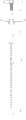
图1为本申请提供的椎体扩张器的主视结构示意图一;Fig. 1 is the front structural schematic diagram 1 of the vertebral body dilator provided by the present application;
图2为本申请提供的椎体扩张器的剖视结构示意图;Fig. 2 is the sectional structural representation of the vertebral body dilator provided by the present application;
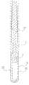
图3为本申请提供的椎体扩张器的局部放大结构示意图一;Fig. 3 is a partial enlarged structural schematic diagram 1 of the vertebral body dilator provided by the present application;
图4为本申请提供的椎体扩张器的立体结构示意图;Fig. 4 is the three-dimensional schematic diagram of the vertebral body dilator provided by the present application;
图5为本申请提供的椎体扩张器的主视结构示意图二;Fig. 5 is the front view structural schematic diagram II of the vertebral body dilator provided by the present application;
图6为本申请提供的椎体扩张器的局部放大结构示意图二;Fig. 6 is a partial enlarged structural schematic diagram II of the vertebral body dilator provided by the present application;
图7为本申请提供的椎体扩张器的局部放大结构示意图三;FIG. 7 is a schematic diagram of a partially enlarged structure of the vertebral body dilator provided by the present application;
图8为本申请提供的椎体扩张器的使用状态结构示意图;Fig. 8 is a structural schematic diagram of the use state of the vertebral body dilator provided by the present application;
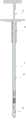
图9为本申请提供的压缩骨折椎体治疗套件的植骨装置的主视结构示意图;Fig. 9 is a front structural schematic view of the bone grafting device of the compression fractured vertebral body treatment kit provided by the present application;
图10为本申请提供的压缩骨折椎体治疗套件的植骨装置的局部放大结构示意图;Fig. 10 is a partial enlarged structural schematic diagram of the bone grafting device of the compression fractured vertebra treatment kit provided by the present application;
图11为本申请提供的压缩骨折椎体治疗套件的植骨装置的立体结构示意图;Fig. 11 is a three-dimensional structural schematic diagram of the bone grafting device of the compression fractured vertebral body treatment kit provided by the present application;
图12为本申请提供的压缩骨折椎体治疗套件的植骨装置的使用状态结构示意图。Fig. 12 is a schematic structural diagram of the bone grafting device in use of the compression fractured vertebral body treatment kit provided by the present application.
其中,图中各附图标记:Wherein, each reference sign in the figure:
1、第一基体; 11、驱动件操作腔;1. The first base body; 11. The operating cavity of the driving part;
2、顶撑结构; 21、固定瓣;2. Top support structure; 21. Fixed flap;
22、撑开瓣; 3、驱动件;22. Stretching the valve; 3. Driving parts;
4、弹性套; 5、持握件;4. Elastic sleeve; 5. Holding piece;
6、植骨装置; 61、第二基体;6. Bone grafting device; 61. Second matrix;
611、导出口; 612、植入件操作腔;611. Export port; 612. Implant operating cavity;
613、端面上固定齿; 62、植入件;613. Fixed teeth on the end face; 62. Implants;
7、椎体。7. Vertebral body.
具体实施方式Detailed ways
为了使本申请所要解决的技术问题、技术方案及有益效果更加清楚明白,以下结合附图及实施例,对本申请进行进一步详细说明。应当理解,此处所描述的具体实施例仅仅用以解释本申请,并不用于限定本申请。In order to make the technical problems, technical solutions and beneficial effects to be solved by the present application clearer, the present application will be further described in detail below in conjunction with the accompanying drawings and embodiments. It should be understood that the specific embodiments described here are only used to explain the present application, and are not intended to limit the present application.
需要说明的是,当元件被称为“固定于”或“设置于”另一个元件,它可以直接在另一个元件上或者间接在该另一个元件上。当一个元件被称为是“连接于”另一个元件,它可以是直接连接到另一个元件或间接连接至该另一个元件上。It should be noted that when an element is referred to as being “fixed” or “disposed on” another element, it may be directly on the other element or be indirectly on the other element. When an element is referred to as being "connected to" another element, it can be directly connected to the other element or indirectly connected to the other element.
需要理解的是,术语“长度”、“宽度”、“上”、“下”、“前”、“后”、“左”、“右”、“竖直”、“水平”、“顶”、“底”、“内”、“外”等指示的方位或位置关系为基于附图所示的方位或位置关系,仅是为了便于描述本申请和简化描述,而不是指示或暗示所指的装置或元件必须具有特定的方位、以特定的方位构造和操作,因此不能理解为对本申请的限制。It is to be understood that the terms "length", "width", "top", "bottom", "front", "rear", "left", "right", "vertical", "horizontal", "top" , "bottom", "inner", "outer" and other indicated orientations or positional relationships are based on the orientations or positional relationships shown in the drawings, and are only for the convenience of describing the application and simplifying the description, rather than indicating or implying No device or element must have a particular orientation, be constructed, and operate in a particular orientation, and thus should not be construed as limiting the application.
此外,术语“第一”、“第二”仅用于描述目的,而不能理解为指示或暗示相对重要性或者隐含指明所指示的技术特征的数量。由此,限定有“第一”、“第二”的特征可以明示或者隐含地包括一个或者更多个该特征。在本申请的描述中,“多个”的含义是两个或两个以上,除非另有明确具体的限定。In addition, the terms "first" and "second" are used for descriptive purposes only, and cannot be interpreted as indicating or implying relative importance or implicitly specifying the quantity of indicated technical features. Thus, a feature defined as "first" and "second" may explicitly or implicitly include one or more of these features. In the description of the present application, "plurality" means two or more, unless otherwise specifically defined.
在椎体扩张术中,传统的膨胀球囊式扩张器由于球囊的弹性较大,扩张方向难以控制,往往难以精准的在需要扩张的位置扩张和支撑。在压缩性骨折的椎体内,球囊往往朝阻力较小的方向扩张,扩张方向不能保证与骨折需复位方向一致,球囊的扩张方向有时甚至与骨折需复位方向相背离,造成更严重的骨折移位、压迫脊髓、产生神经损伤症状等。In vertebral body dilatation, due to the high elasticity of the balloon, the traditional expansion balloon dilator is difficult to control the direction of expansion, and it is often difficult to accurately expand and support the position that needs to be expanded. In vertebral bodies with compression fractures, the balloon tends to expand toward the direction of less resistance, and the direction of expansion cannot be guaranteed to be consistent with the direction of fracture reduction. Sometimes, the expansion direction of the balloon even deviates from the direction of fracture reduction, resulting in more serious Displacement of fractures, compression of the spinal cord, and symptoms of nerve damage.
如图1至图4所示,本申请提供一种椎体扩张器,包括第一基体1、连接于第一基体1上的顶撑结构2以及与顶撑结构2驱动连接的驱动件3,驱动件3能够驱动顶撑结构2向椎体扩张器的一侧撑开。As shown in Figures 1 to 4, the present application provides a vertebral body expander, including a
其中,第一基体1作为顶撑结构2的安装基体,具体的,第一基体1可以为杆件、管件、基座等。顶撑结构2伸入至椎体待扩张复位的位置,顶撑结构2在驱动件3的驱动下,向椎体扩张器的一侧撑开,该侧即为顶撑结构2的展开侧,以使顶撑结构2能够沿指定方向定向扩张。在使用时,将顶撑结构2的展开侧贴靠在椎体的需复位位置,通过驱动件3驱动顶撑结构2沿指定方向(例如椎体需复位方向)扩张,实现对椎体的扩张和支撑。相比于传统的球囊式扩张器,本申请的椎体扩张器能够按需沿复位方向定向扩张,避免扩张方向与所需复位方向背离造成对椎体的二次损伤,有效保护椎体,扩张效果相比于传统的球囊式扩张器更好。Wherein, the
如图2和图3所示,在本申请的一个实施例中,第一基体1具有驱动件操作腔11,顶撑结构2位于驱动件操作腔11的长度方向的第一端,驱动件3能够沿驱动件操作腔11的长度方向可运动地安装于驱动件操作腔11,驱动件3沿驱动件操作腔11运动至预定位置时,能够挤压顶撑结构2向驱动件3的运动方向的一侧撑开。As shown in FIGS. 2 and 3 , in one embodiment of the present application, the
其中,驱动件3能够沿驱动件操作腔11的长度方向可运动地安装于驱动件操作腔11,具体是指,驱动件3能够沿驱动件操作腔11的长度方向伸缩和/或转动。驱动件3运动至预定位置时,与顶撑结构2接触,并对顶撑结构2造成挤压,迫使顶撑结构2向驱动件运动方向的一侧撑开。Wherein, the
在本申请的一个实施例中,第一基体1具体可以是直径为5mm-7mm的圆管,驱动件操作腔11具体为管腔。顶撑结构2位于圆管的第一端,也即管腔的第一端。驱动件3沿管腔的轴向可运动地安装于管腔,驱动件3沿管腔的轴向运动至预定位置时,挤压顶撑结构2向驱动件3的运动方向的一侧撑开。In an embodiment of the present application, the
如图5至图7所示,在本申请的一个实施例中,顶撑结构2包括连接于第一基体1上的固定瓣21和撑开瓣22,固定瓣21的内壁和撑开瓣22的内壁中,至少一者具有沿驱动件操作腔11的长度方向倾斜的斜面,驱动件3运动至与斜面接触时,能够挤压撑开瓣22向驱动件3的运动方向的一侧撑开。其中,撑开瓣22的撑开高度至少需达到2cm,以使顶撑结构2具有足够的顶撑扩张范围,能够较大程度恢复严重压缩骨折的椎体。该顶撑结构2相比于传统的球囊顶撑扩张范围更大,能够较大程度地恢复压缩骨折椎体的高度。As shown in FIGS. 5 to 7 , in one embodiment of the present application, the supporting
其中,固定瓣21固定连接在第一基体1上,固定瓣21不具备张开功能。撑开瓣22能够相对固定瓣21张开或合拢。固定瓣21的内壁和/或撑开瓣22的内壁上设有斜面,具体的,当固定瓣21的内壁设有斜面,撑开瓣22的内壁不具有斜面时,驱动件3运动至与固定瓣21内壁的斜面接触,由于固定瓣21无法张开,迫使驱动件3向撑开瓣22一侧弯曲,从而挤压撑开瓣22向外张开;当撑开瓣22的内壁设有斜面时,驱动件3运动至与撑开瓣22内壁的斜面接触,并通过挤压撑开瓣22内壁的斜面,使撑开瓣22向驱动件3的运动方向的一侧撑开。当固定瓣21的内壁和撑开瓣22的内壁上均设有斜面时,固定瓣21内壁的斜面倾斜度应小于撑开瓣22内壁的斜面倾斜度。斜面沿驱动件操作腔11的长度方向倾斜,具体是指,当驱动件3挤压斜面时,使撑开瓣22能够向外展开的方向倾斜。具体的,顶撑结构2的长度范围在26mm-36mm之间,以使顶撑结构2具有足够伸入椎体的长度和撑开空间。该长度范围适用于大部分患者的胸腰椎椎体。在其他实施例中,还可设有其他规格(其他长度范围或其他顶撑扩张范围)的顶撑结构2。根据术前测量的椎体长度,选配适合长度范围的顶撑结构2用于椎体的顶撑扩张。相比于传统的球囊扩张器,本申请的顶撑结构2不会出现顶撑压力过大导致球囊破裂的问题,通过驱动件3挤压撑开瓣22内壁张开,扩张支撑力更加集中于需要顶撑扩张的一侧,撑开定向性好,顶撑结构2的结构强度更高,也有利于提供更大的扩张支撑力。Wherein, the fixed
如图3所示,在本申请的一个实施例中,撑开瓣22的内壁上设有斜面,固定瓣21的内壁设有避空槽。驱动件3在运动时,始终保持与固定瓣21的避让,固定瓣21上不会受到驱动件3的挤压。As shown in FIG. 3 , in one embodiment of the present application, the inner wall of the expanding
如图6和图7所示,在本申请的一个实施例中,撑开瓣22可弹性弯曲地连接于第一基体1上。As shown in FIGS. 6 and 7 , in one embodiment of the present application, the
驱动件3驱动撑开瓣22扩张时,撑开瓣22向驱动件3的运动方向的一侧弹性弯曲变形,并随之撑开椎体;驱动件3回退时,撑开瓣22依靠自身弹性回退至初始状态。其中,固定瓣21和撑开瓣22均可以与第一基体1过程一体式结构。第一基体1、固定瓣21和撑开瓣22采用钛合金等韧性较强的金属制成,不仅具有较高的结构强度,要具有足够的韧性保持撑开瓣22的回弹。When the
如图3所示,在本申请的一个实施例中,驱动件3为推杆,推杆与驱动件操作腔11的内壁螺纹连接,推杆的第一端能够挤压撑开瓣22的内壁向驱动件3的运动方向的一侧撑开。As shown in FIG. 3 , in one embodiment of the present application, the driving
使用时,转动推杆,由于推杆与驱动件操作腔11的内壁螺纹连接,推杆将相对驱动件操作腔11伸缩。当推杆伸至预定位置时,推杆的第一端挤压撑开瓣22的内壁向驱动件3的运动方向的一侧撑开,并随着推杆的不断向前伸出,增大撑开瓣22的撑开程度;当转动推杆向后缩回时,推杆的第一端失去对撑开瓣22的挤压力,撑开瓣22依靠自身弹性回缩。When in use, when the push rod is rotated, since the push rod is threadedly connected with the inner wall of the driving
如图3所示,在一个实施例中,推杆包括锥形推杆头部,锥形推杆头部的锥面与撑开瓣22内壁的斜面对应,以使锥形推杆头部始终与撑开瓣22的内壁保持面接触,从而使锥形推杆头部更好的挤压撑开瓣22向外侧撑开。推杆的尾部为T字型手柄,便于手动旋拧推杆。As shown in FIG. 3 , in one embodiment, the push rod includes a tapered push rod head, and the conical surface of the tapered push rod head corresponds to the inclined surface of the inner wall of the
如图3和图4所示,在本申请的一个实施例中,还包括弹性套4,弹性套4包覆于顶撑结构2的外侧。As shown in FIG. 3 and FIG. 4 , in one embodiment of the present application, an
其中,弹性套4可弹性收缩或者弹性扩张地包覆于顶撑结构2的外侧。当顶撑结构2扩张时,顶撑结构2能够将弹性套4撑开;当顶撑结构2收缩时,弹性套4能够依靠自身弹性回缩至初始状态。Wherein, the
当顶撑结构2撑开时,固定瓣21和撑开瓣22之间的间隙增大。为防止椎体内骨质、碎屑等卡嵌在间隙中,致使撑开瓣22无法回位;如图8所示,通过弹性套4能够将顶撑结构2与椎体内的骨质隔离,椎体7内的骨质无法透过弹性套4进入固定瓣21和撑开瓣22之间的间隙,因此,不会导致撑开瓣22卡死,撑开瓣22无法回位的问题。弹性套4还能起到阻隔外界血液、水汽、碎屑进入顶撑结构2内部的阻隔保护作用,保证内部结构清洁,方便消毒杀菌后二次使用。弹性套4具体可以为聚氨酯橡胶弹性套、硅橡胶弹性套等。When the supporting
如图4所示,在本申请的一个实施例中,还包括可拆卸地连接于第一基体1上的持握件5。As shown in FIG. 4 , in one embodiment of the present application, a holding
使用者使用椎体扩张器时,持握在持握件5上进行操作。持握件5通过插接、嵌套、卡接或螺纹连接等可拆卸连接方式与第一基体1连接,便于持握件5的拆卸和安装。具体的,持握件5为T型持握件,更便于使用者的持握。When the user uses the vertebral body expander, he or she holds the holding
本申请提供一种压缩骨折椎体治疗套件,包括上述实施例中的椎体扩张器。The present application provides a treatment kit for compressing a fractured vertebral body, including the vertebral body expander in the above embodiment.
由于该压缩骨折椎体治疗套件具有上述实施例中的椎体扩张器,因此,也具有上述实施例中的椎体扩张器的优点。Since the treatment kit for compressive fractured vertebral body has the vertebral body expander in the above-mentioned embodiment, it also has the advantages of the vertebral body expander in the above-mentioned embodiment.
在使用本申请提供的压缩骨折椎体治疗套件之前,还需要通过常规的椎弓根置钉器械,行经椎弓根开口、开路、丝攻的操作,建立常规的椎弓根螺钉通道。然后再经过椎弓根螺钉通道置入本申请提供的椎体扩张器,通过椎体扩张器进行椎体顶撑复位治疗。Before using the compression fracture vertebral body treatment kit provided by the present application, conventional pedicle screw placement instruments need to be operated through the pedicle opening, opening, and tapping to establish a conventional pedicle screw channel. Then insert the vertebral body expander provided by the present application through the pedicle screw channel, and carry out the vertebral body support reduction treatment through the vertebral body expander.
如图9至图12所示,在本申请的一个实施例中,还包括植骨装置6,植骨装置6包括第二基体61和植入件62,第二基体61具有导出口611和植入件操作腔612,植入件62能够伸入至植入件操作腔612。As shown in Figures 9 to 12, in one embodiment of the present application, a
其中,第二基体61具体可以为植骨管。第二基体61的一端为导入口,另一端为导出口611,植入件操作腔612为植骨管的管腔。具体的,导入口为喇叭型或漏斗型导入口,以便于装入待植入的自体骨骨粒或骨水泥。植入件62从导入口伸入至植入件操作腔612,并推动植入件操作腔612内的自体骨骨粒或骨水泥朝导出口611运动,最终从导出口611植入椎体内待填充的空腔中。Wherein, the
椎体扩张器将骨折或塌陷的椎体扩张复位后,椎体内形成有空腔。再将植骨装置6插入该空腔通道的骨性外表面,用于向该空腔内填充自体骨骨粒或骨水泥等填充物。After the vertebral body expander expands and resets the fractured or collapsed vertebral body, a cavity is formed in the vertebral body. The
如图10所示,在本申请的一个实施例中,导出口611的端面上设有固定齿613。As shown in FIG. 10 , in one embodiment of the present application, fixed
具体的,固定齿613具有多个,多个固定齿613绕植骨管的轴向布置。植骨装置6插入椎弓根外骨性通道入口后,固定齿613能够止抵在骨性通道周围骨质上,增大第二基体61与椎体表面的摩擦力,防止在装填骨料时,第二基体61与椎体骨发生打滑或移动。Specifically, there are multiple fixing
如图9所示,在本申请的一个实施例中,第二基体61与持握件5可拆卸地连接。椎体扩张器与植骨装置6可共用持握件5,以减少压缩骨折椎体治疗套件的零部件个数。As shown in FIG. 9 , in one embodiment of the present application, the
使用者使用植骨装置6时,持握在持握件5上进行操作。椎体扩张器将椎体扩张复位后,将第一基体1和驱动件3从持握件5上卸下,再将第二基体61安装至持握件5上。持握件5通过插接、嵌套、卡接或螺纹连接等可拆卸连接方式与第二基体61连接。具体的,持握件5为T型持握件,更便于使用者的持握。When the user uses the
本申请提供的压缩骨折椎体治疗套件在使用时,先将本申请提供的椎体扩张器置入预先开设好的椎弓根螺钉通道。固定或持握在持握件5上,以固定第一基体1。通过转动驱动件3,即推杆,沿第一基体1伸入至预定位置,使推杆头部挤压撑开瓣22,使撑开瓣22向外张开,以起到顶撑复位压缩骨折椎体的作用。顶撑复位后,驱动推杆反向转动,以使推杆沿第一基体1退出预定位置,撑开瓣22失去挤压力,并依靠撑开瓣22的自身弹性回缩至初始位置,复位顶撑结构2。完成椎体扩张复位后,将推杆上的手柄和持握件5从第一基体1上卸下,将植骨装置6的第二基体61沿第一基体1外壁套入第一基体1,至第二基体61上的固定齿613止抵在椎体表面骨质后,再将第一基体1从第二基体61中抽出移除,完成植骨装置6与椎体扩张器的替换。再向第二基体61内填入待植骨料,通过植入件62推动待植骨料装填至椎体空腔,将之前撑开的椎体空腔填满,并通过植入件62推挤植入骨料,以增强压缩骨折椎体的承重能力以及促进骨性愈合。最后对椎弓根螺钉通道进行植骨封闭,完成植骨装填治疗。When using the compression fractured vertebral body treatment kit provided by the present application, the vertebral body expander provided by the present application is inserted into the pre-opened pedicle screw channel. Fix or hold on the holding
如图12所示,当椎体扩张器顶撑一侧的顶撑效果不足以达到目标效果时,可以在另一侧的椎弓根上同样开设椎弓根螺钉通道,通过对侧椎弓根螺钉通道再次行压缩骨折椎体的顶撑复位和植骨治疗操作。As shown in Figure 12, when the propping effect on one side of the vertebral body dilator is not enough to achieve the target effect, a pedicle screw channel can also be opened on the pedicle on the other side, through which the contralateral pedicle screw can The tunnel was again subjected to compression of the fractured vertebral body, supporting reduction and bone grafting.
以上所述仅为本申请的较佳实施例而已,并不用以限制本申请,凡在本申请的精神和原则之内所作的任何修改、等同替换和改进等,均应包含在本申请的保护范围之内。The above descriptions are only preferred embodiments of the application, and are not intended to limit the application. Any modifications, equivalent replacements and improvements made within the spirit and principles of the application should be included in the protection of the application. within range.
Claims (10)
Translated fromChinesePriority Applications (1)
| Application Number | Priority Date | Filing Date | Title |
|---|---|---|---|
| CN202211418619.5ACN115770096A (en) | 2022-11-14 | 2022-11-14 | Centrum expander and compression fracture centrum treatment external member |
Applications Claiming Priority (1)
| Application Number | Priority Date | Filing Date | Title |
|---|---|---|---|
| CN202211418619.5ACN115770096A (en) | 2022-11-14 | 2022-11-14 | Centrum expander and compression fracture centrum treatment external member |
Publications (1)
| Publication Number | Publication Date |
|---|---|
| CN115770096Atrue CN115770096A (en) | 2023-03-10 |
Family
ID=85389040
Family Applications (1)
| Application Number | Title | Priority Date | Filing Date |
|---|---|---|---|
| CN202211418619.5APendingCN115770096A (en) | 2022-11-14 | 2022-11-14 | Centrum expander and compression fracture centrum treatment external member |
Country Status (1)
| Country | Link |
|---|---|
| CN (1) | CN115770096A (en) |
Cited By (1)
| Publication number | Priority date | Publication date | Assignee | Title |
|---|---|---|---|---|
| CN118078403A (en)* | 2024-02-29 | 2024-05-28 | 郑州壹毫米医药科技有限公司 | Metal bone needle |
Citations (10)
| Publication number | Priority date | Publication date | Assignee | Title |
|---|---|---|---|---|
| US20040102774A1 (en)* | 2002-11-21 | 2004-05-27 | Trieu Hai H. | Systems and techniques for intravertebral spinal stabilization with expandable devices |
| WO2005048856A1 (en)* | 2003-11-10 | 2005-06-02 | Umc Utrecht Holding B.V. | Expandable implant for treating fractured and/or collapsed bone |
| CN103393452A (en)* | 2013-07-17 | 2013-11-20 | 苏州爱得科技发展有限公司 | Type-I bone cement injection device |
| CN203468728U (en)* | 2013-07-17 | 2014-03-12 | 苏州爱得科技发展有限公司 | Bone cement pushing-injection device |
| CN103919594A (en)* | 2013-01-14 | 2014-07-16 | 林士闳 | Vertebral Reamer |
| CN109171850A (en)* | 2018-10-18 | 2019-01-11 | 郑博伦 | A kind of intervertebral opening device for lumbar treatment |
| CN211300126U (en)* | 2019-10-31 | 2020-08-21 | 谢少鹏 | Vertebral body expansion device |
| CN112790855A (en)* | 2021-02-08 | 2021-05-14 | 北京理贝尔生物工程研究所有限公司 | Laminar distraction device |
| CN114007534A (en)* | 2019-06-14 | 2022-02-01 | 美多斯国际有限公司 | Biomaterial delivery devices and related systems and methods |
| CN219700085U (en)* | 2022-11-14 | 2023-09-19 | 深圳大学 | Vertebral body expander and compressed fracture vertebral body treatment suite |
- 2022
- 2022-11-14CNCN202211418619.5Apatent/CN115770096A/enactivePending
Patent Citations (10)
| Publication number | Priority date | Publication date | Assignee | Title |
|---|---|---|---|---|
| US20040102774A1 (en)* | 2002-11-21 | 2004-05-27 | Trieu Hai H. | Systems and techniques for intravertebral spinal stabilization with expandable devices |
| WO2005048856A1 (en)* | 2003-11-10 | 2005-06-02 | Umc Utrecht Holding B.V. | Expandable implant for treating fractured and/or collapsed bone |
| CN103919594A (en)* | 2013-01-14 | 2014-07-16 | 林士闳 | Vertebral Reamer |
| CN103393452A (en)* | 2013-07-17 | 2013-11-20 | 苏州爱得科技发展有限公司 | Type-I bone cement injection device |
| CN203468728U (en)* | 2013-07-17 | 2014-03-12 | 苏州爱得科技发展有限公司 | Bone cement pushing-injection device |
| CN109171850A (en)* | 2018-10-18 | 2019-01-11 | 郑博伦 | A kind of intervertebral opening device for lumbar treatment |
| CN114007534A (en)* | 2019-06-14 | 2022-02-01 | 美多斯国际有限公司 | Biomaterial delivery devices and related systems and methods |
| CN211300126U (en)* | 2019-10-31 | 2020-08-21 | 谢少鹏 | Vertebral body expansion device |
| CN112790855A (en)* | 2021-02-08 | 2021-05-14 | 北京理贝尔生物工程研究所有限公司 | Laminar distraction device |
| CN219700085U (en)* | 2022-11-14 | 2023-09-19 | 深圳大学 | Vertebral body expander and compressed fracture vertebral body treatment suite |
Cited By (1)
| Publication number | Priority date | Publication date | Assignee | Title |
|---|---|---|---|---|
| CN118078403A (en)* | 2024-02-29 | 2024-05-28 | 郑州壹毫米医药科技有限公司 | Metal bone needle |
Similar Documents
| Publication | Publication Date | Title |
|---|---|---|
| US20050070911A1 (en) | Apparatus and methods for reducing compression bone fractures using high strength ribbed members | |
| KR101564559B1 (en) | Nested expandable sleeve implant | |
| US6730095B2 (en) | Retrograde plunger delivery system | |
| US20190262052A1 (en) | Devices and methods for treating bone | |
| US7488337B2 (en) | Apparatus and methods for bone, tissue and duct dilatation | |
| US8663294B2 (en) | Apparatus and methods for vertebral augmentation using linked expandable bodies | |
| CN102274066B (en) | Trans-vertebral-pedicle centrum fracture restorer | |
| US20040049202A1 (en) | Spinal grooved director with built in balloon and method of using same | |
| CN104306054B (en) | A kind of expansible vertebral plasty support | |
| CN104248465B (en) | Bone grafting device for vertebral body compression fracture | |
| CN115770096A (en) | Centrum expander and compression fracture centrum treatment external member | |
| CN219700085U (en) | Vertebral body expander and compressed fracture vertebral body treatment suite | |
| WO2022062779A1 (en) | Transpedicular intervertebral fusion system | |
| CN103622734B (en) | Percutaneous vertebral body expansion formation system | |
| CN114652419A (en) | Bone cement pedicle screw with expandable mesh bag | |
| CN206120427U (en) | Integral type expansible sacculus bag bagging apparatus | |
| CN118717262A (en) | A pedicle bone grafting kit | |
| CN204147102U (en) | A kind of expansible vertebral plasty support | |
| RU182010U1 (en) | DEVICE FOR OPEN INTRAOPERATIVE CEMENT HYDROPLASTIC UNDER REVISION INTERVENTIONS ON THE SPINE | |
| CN214434448U (en) | A three-column fixation-based intravertebral expansion device and implant sleeve | |
| CN111449745A (en) | A three-column fixation-based intravertebral expansion device, implant sleeve and implant method | |
| CN212755852U (en) | Vertebroplasty reconstruction system | |
| CN216167793U (en) | Injection device combining different parameters of bone cement | |
| CN214837642U (en) | Adjustable percutaneous bone cement nail props pressure | |
| CN213525420U (en) | Percutaneous stent expansion and scraping vertebroplasty device |
Legal Events
| Date | Code | Title | Description |
|---|---|---|---|
| PB01 | Publication | ||
| PB01 | Publication | ||
| SE01 | Entry into force of request for substantive examination | ||
| SE01 | Entry into force of request for substantive examination |