CN115770092A - Strong tension nail for cancellous bone - Google Patents
Strong tension nail for cancellous boneDownload PDFInfo
- Publication number
- CN115770092A CN115770092ACN202211582022.4ACN202211582022ACN115770092ACN 115770092 ACN115770092 ACN 115770092ACN 202211582022 ACN202211582022 ACN 202211582022ACN 115770092 ACN115770092 ACN 115770092A
- Authority
- CN
- China
- Prior art keywords
- nail
- main nail
- bone tissue
- tail
- cancellous bone
- Prior art date
- Legal status (The legal status is an assumption and is not a legal conclusion. Google has not performed a legal analysis and makes no representation as to the accuracy of the status listed.)
- Withdrawn
Links
- 210000000988bone and boneAnatomy0.000titleclaimsabstractdescription134
- 229910001069Ti alloyInorganic materials0.000claimsdescription3
- 239000010935stainless steelSubstances0.000claimsdescription2
- 229910001220stainless steelInorganic materials0.000claimsdescription2
- 238000011084recoveryMethods0.000abstractdescription17
- 238000000034methodMethods0.000abstractdescription13
- 239000007943implantSubstances0.000abstractdescription3
- 230000000399orthopedic effectEffects0.000abstractdescription3
- 230000035515penetrationEffects0.000abstract1
- 206010017076FractureDiseases0.000description29
- 208000010392Bone FracturesDiseases0.000description27
- 230000006378damageEffects0.000description10
- 230000009286beneficial effectEffects0.000description9
- 230000000694effectsEffects0.000description7
- 238000010586diagramMethods0.000description6
- 208000027418Wounds and injuryDiseases0.000description4
- 208000014674injuryDiseases0.000description4
- 238000003780insertionMethods0.000description4
- 230000037431insertionEffects0.000description4
- 238000009434installationMethods0.000description4
- 230000008569processEffects0.000description4
- 230000008439repair processEffects0.000description4
- 230000035807sensationEffects0.000description4
- 238000013459approachMethods0.000description3
- 210000003692iliumAnatomy0.000description3
- 210000004197pelvisAnatomy0.000description3
- 206010061549Sensation of foreign bodyDiseases0.000description2
- 230000007797corrosionEffects0.000description2
- 238000005260corrosionMethods0.000description2
- 238000013461designMethods0.000description2
- 230000006870functionEffects0.000description2
- 230000035876healingEffects0.000description2
- 210000001621ilium boneAnatomy0.000description2
- 210000001696pelvic girdleAnatomy0.000description2
- 238000011160researchMethods0.000description2
- 238000001356surgical procedureMethods0.000description2
- 210000002303tibiaAnatomy0.000description2
- 210000003906tibiofibular jointAnatomy0.000description2
- XLYOFNOQVPJJNP-UHFFFAOYSA-NwaterSubstancesOXLYOFNOQVPJJNP-UHFFFAOYSA-N0.000description2
- 208000012886VertigoDiseases0.000description1
- 238000004891communicationMethods0.000description1
- 238000006073displacement reactionMethods0.000description1
- 238000003384imaging methodMethods0.000description1
- 230000006872improvementEffects0.000description1
- 210000000629knee jointAnatomy0.000description1
- 238000012986modificationMethods0.000description1
- 230000004048modificationEffects0.000description1
- 238000000465mouldingMethods0.000description1
- 239000011664nicotinic acidSubstances0.000description1
- 238000005381potential energyMethods0.000description1
- 238000010079rubber tappingMethods0.000description1
- 238000009987spinningMethods0.000description1
- 230000001225therapeutic effectEffects0.000description1
- 206010043827tibia fractureDiseases0.000description1
Images


Landscapes
- Surgical Instruments (AREA)
Abstract
Translated fromChinese
Description
Translated fromChinese技术领域technical field
本发明涉及骨科外科手术植入物技术领域,尤其是一种用于松质骨的强力拉力钉。The invention relates to the technical field of orthopedic surgery implants, in particular to a strong tension nail for cancellous bone.
背景技术Background technique
车祸、摔倒等暴力冲击极易造成骨折,针对骨盆、胫骨平台、股骨髁等松质骨丰富部位的损伤,其固定复位困难,以微创的方式实现生物力学力学性能佳的固定是研究的热点。目前,主流的手术治疗方式是通过置入拉力钉来固定骨折部位的骨组织。Violent impacts such as car accidents and falls can easily cause fractures. For injuries to areas rich in cancellous bone such as the pelvis, tibial plateau, and femoral condyles, it is difficult to fix and reset. It is the research to achieve fixation with good biomechanical properties in a minimally invasive way. hotspot. At present, the mainstream surgical treatment method is to fix the bone tissue at the fracture site by inserting tension nails.
本申请的发明人致力于骨科医疗器械的研究,并与2021年申请了公开号为CN215534937U的下胫腓联合微动弹性内固定植入物,它由拉力钉、套筒和弹性圈构成,依靠拉力钉和套筒间之间的轴向间隙、径向间隙实现下胫腓联合的微动功能;依靠弹性圈的弹性势能实现下胫腓联合的弹性固定;针对下胫腓联合损伤修复,微动弹性固定修复更符合人体下胫腓联合的工作原理,更贴近其原本的工作状态,微动弹性固定修复更具备仿生性能。该申请中公开了现有技术拉力钉的结构,拉力钉包括了自攻刃口、松质骨螺纹、横杆、外压头和内六角孔。可见,现有技术的拉力钉为螺钉式的结构,其主要是依靠螺纹来咬合骨组织,也就是说,通过螺间距来拉扯骨组织。由于螺间距较小,因此拉力钉的吃骨量较少,不能很好的拉扯骨折部位的骨组织,导致骨组织之间固定不牢,骨折部位的骨组织间隙大,不利于骨组织后期恢复;而且,由于拉力钉为螺钉式的结构,在患者活动的过程中,拉力钉有自旋的风险,拉力钉一旦产生自旋运动,就会减小对骨折部位的拉扯力,同样不利于骨折部位骨组织的后期恢复;此外,现有技术的拉力钉并不具备拉力可调的功能,也会延长骨组织的恢复时间以及影响骨组织的恢复。The inventor of this application is committed to the research of orthopedic medical devices, and in 2021 applied for a micro-motion elastic internal fixation implant for the inferior tibiofibular syndesmosis with the publication number CN215534937U, which consists of a tension nail, a sleeve and an elastic ring. The axial gap and radial gap between the tension nail and the sleeve realize the micro-movement function of the syndesmosis; rely on the elastic potential energy of the elastic ring to realize the elastic fixation of the syndesmosis; for the repair of the syndesmosis injury, micro The dynamic elastic fixed repair is more in line with the working principle of the human inferior tibiofibular syndesmosis, and is closer to its original working state, and the micro elastic fixed repair has more bionic performance. This application discloses the structure of the tension nail in the prior art. The tension nail includes a self-tapping edge, a cancellous bone screw thread, a cross bar, an external pressure head and an inner hexagonal hole. It can be seen that the pulling nails in the prior art are screw-type structures, which mainly rely on threads to engage bone tissue, that is to say, pull bone tissue through the screw pitch. Due to the small screw pitch, the amount of bone eaten by the tension nail is less, and the bone tissue at the fracture site cannot be pulled well, resulting in unstable fixation between the bone tissue and large gaps between the bone tissue at the fracture site, which is not conducive to the later recovery of bone tissue. ; Moreover, because the tension nail is a screw-type structure, the tension nail has the risk of spinning during the patient's activities. Once the tension nail spins, it will reduce the pulling force on the fracture site, which is also not conducive to fractures. In addition, the tension nails in the prior art do not have the function of adjustable tension, which will also prolong the recovery time of bone tissue and affect the recovery of bone tissue.
发明内容Contents of the invention
针对传统拉力钉拉扯骨量少、固定效果差、自旋以及拉力不可调的技术问题,本发明提供一种用于松质骨的强力拉力钉。Aiming at the technical problems of the traditional tension nails that pull less bone, poor fixation effect, and non-adjustable spin and tension, the present invention provides a strong tension nail for cancellous bone.
本发明所采用的技术方案是:The technical scheme adopted in the present invention is:
用于松质骨的强力拉力钉,包括主钉和连接在主钉顶端的尾套,主钉为柱状结构,主钉内沿主钉轴向贯穿的布置有用于克氏针通过的中心通道,主钉靠近底端的侧面设置有螺旋刀片。手术时,利用克氏针定位,通过C臂显影,确定拉力钉的置入位置,再将主钉的中心通道穿过克氏针,敲入主钉,由于主钉的底端设置有螺旋刀片,因此主钉在敲入的过程随螺旋刀片的螺旋纹路旋转缓慢进入骨组织,待主钉置入到预定部位后,拔出克氏针,将尾套与主钉相连即可。可见,相比于传统螺纹方式的拉力钉而言,本发明通过在主钉的底端设置螺旋刀片来替代传统的螺纹。首先,螺旋刀片具有刃口,可切割骨组织,降低螺旋刀片与骨组织之间的摩擦力,使主钉更加顺畅的置入到骨组织中,降低了手术操作的困难,提高手术效率;而且螺旋进入方式能最小程度破坏骨组织;其次,由于螺纹刀片为螺旋状,因此可以起到很好的限位作用,能很好的限制骨组织内的主钉在横向和竖向两个方向上转动;再者,相较于螺纹方式而言,螺旋刀片的吃骨量更大,与骨组织之间的接触面积更广,拉扯骨组织的力量更强,与骨组织之间固定更牢,从而保证骨折部位相邻的骨组织贴合更紧密,有利于患者骨折部位骨组织的后期恢复,能有效缩短患者的康复期。The strong tensile nail for cancellous bone, including the main nail and the tail sleeve connected to the top of the main nail, the main nail is a columnar structure, and there is a central channel for the passage of the Kirschner wire inside the main nail along the axial direction of the main nail. The side of the main nail near the bottom end is provided with a helical blade. During the operation, use the Kirschner wire for positioning, and use the C-arm to determine the insertion position of the tension nail, and then pass the central channel of the main nail through the Kirschner wire, and then knock in the main nail. Since the bottom of the main nail is equipped with a helical blade , so the main nail slowly enters the bone tissue with the helical pattern of the helical blade during the knock-in process. After the main nail is placed at the predetermined position, pull out the Kirschner wire and connect the tail sleeve with the main nail. It can be seen that, compared with the tension nail of the traditional thread mode, the present invention replaces the traditional screw thread by arranging a helical blade at the bottom end of the main nail. Firstly, the helical blade has a cutting edge, which can cut bone tissue, reduce the friction between the helical blade and bone tissue, and make the main nail be inserted into the bone tissue more smoothly, which reduces the difficulty of operation and improves the operation efficiency; and The helical entry method can minimize the damage to the bone tissue; secondly, because the threaded blade is helical, it can play a good role in limiting the position of the main nail in the bone tissue in both horizontal and vertical directions. Moreover, compared with the screw thread method, the helical blade has a larger bone-eating capacity, a wider contact area with the bone tissue, a stronger force to pull the bone tissue, and a stronger fixation with the bone tissue. This ensures that the adjacent bone tissue at the fracture site fits closer, which is beneficial to the later recovery of the bone tissue at the fracture site of the patient, and can effectively shorten the recovery period of the patient.
进一步的是,螺旋刀片的螺旋角β为10°~80°。螺旋刀片的螺旋角不能过大,也不能过小。螺旋角过大,螺旋刀片就会较为笔直,主钉在骨组织中就不能起到很好的限位作用,主钉在纵向上有位移的风险;螺旋角设置过小,螺旋刀片较为弯曲且纹路较多,就会增加了主钉的置入困难,而且破坏的骨组织就较多,因此,本发明优选的螺旋角β为10°~80°。Further, the helix angle β of the helical blade is 10°-80°. The helix angle of the helical blade should neither be too large nor too small. If the helix angle is too large, the helical blade will be relatively straight, and the main nail will not be able to play a good limiting role in the bone tissue, and the main nail may be displaced in the longitudinal direction; if the helix angle is set too small, the helical blade will be more curved and More textures will increase the difficulty of inserting the main nail, and more bone tissue will be destroyed. Therefore, the preferred helix angle β of the present invention is 10°-80°.
进一步的是,螺旋刀片与主钉一体成型,增强螺旋刀片与主钉连接的稳定性,降低两者断裂的风险,可直接上机床在主钉上铣出螺旋刀片。Furthermore, the helical blade and the main nail are integrally formed to enhance the stability of the connection between the helical blade and the main nail, and reduce the risk of the two breaking. The helical blade can be milled out on the main nail directly on the machine tool.
进一步的是,中心通道内靠近主钉顶部的一端设置有内螺纹;所述尾套包括防旋尾卡和调节螺栓,防旋尾卡为柱状结构,防旋尾卡内沿防旋尾卡轴向布置有通孔,调节螺栓包括螺帽和螺杆,调节螺栓穿过防旋尾卡的通孔与主钉螺纹连接。这也是本发明设计的巧妙之处,本发明的调节螺栓穿过防旋尾卡的通孔与主钉螺纹连接,也就是说,通过拧动调节螺栓可拉紧主钉与防旋尾卡,换句话说,通过拧动螺栓可将主钉拉向防旋尾卡移动。当主钉穿过正常骨组织与骨折部位的骨组织后,动过拧动螺栓将骨折部位的骨组织拉向正常的骨组织,使两块骨组织逐渐靠拢,减少两块骨组织之间的间隙,使两块骨组织贴合更加紧密,从而有利于患者骨折部位骨组织的后期恢复,能有效缩短患者的康复期。综上,本发明通过调节螺栓可调节主钉的拉力,也就是调节相邻两块骨组织之间的间隙,使两块骨组织的贴合程度最佳,从而有利于患者骨折部位骨组织的后期恢复。Further, the end of the central channel close to the top of the main nail is provided with an internal thread; the tail sleeve includes an anti-rotation tail clip and an adjusting bolt. A through hole is arranged in the direction, and the adjusting bolt includes a nut and a screw rod, and the adjusting bolt passes through the through hole of the anti-rotation tail card and is threadedly connected with the main nail. This is also the ingenuity of the design of the present invention. The adjusting bolt of the present invention passes through the through hole of the anti-rotation tail clip and is threadedly connected with the main nail. That is to say, the main nail and the anti-rotation tail clip can be tightened by turning the adjusting bolt. In other words, by turning the bolt, the main nail can be pulled towards the anti-spin tail clip to move. When the main nail passes through the normal bone tissue and the bone tissue at the fracture site, the bone tissue at the fracture site is pulled toward the normal bone tissue by turning the bolt, so that the two bone tissues gradually move closer together and the gap between the two bone tissues is reduced , so that the two bone tissues fit together more tightly, which is beneficial to the later recovery of the bone tissue at the fracture site of the patient, and can effectively shorten the rehabilitation period of the patient. In summary, the present invention can adjust the pulling force of the main nail by adjusting the bolt, that is, adjust the gap between two adjacent bone tissues, so that the two bone tissues fit best, thereby facilitating the bone tissue at the fracture site of the patient. Late recovery.
进一步的是,主钉的顶部设置有凹槽,凹槽的直径大于防旋尾卡的外径,防旋尾卡嵌入式的布置在主钉的凹槽内;在完成拉力钉的置入后,防旋尾卡的顶部与骨组织表面齐平。将防旋尾卡嵌入式的布置在主钉的凹槽内,一方面能有效缩短拉力钉的总长度,避免拉力钉过度置入骨组织,损伤骨组织;另一方面,将防旋尾卡隐藏在凹槽内,避免单独设置的防旋尾卡在骨组织中转动,从而影响拉力钉的固定效果。防旋尾卡置入骨组织过深不便于后期拉力钉的取出;防旋尾卡裸露在骨组织表面,会给患者来带异物感,带来不适。为此本发明设计防旋尾卡的顶部与骨组织表面齐平,使患者没有异物感,不会给患者带来不适感。Further, the top of the main nail is provided with a groove, and the diameter of the groove is larger than the outer diameter of the anti-rotation tail clip, and the anti-rotation tail clip is embedded in the groove of the main nail; , the top of the anti-rotation tail clip is flush with the surface of bone tissue. The anti-rotation tail clip is embedded in the groove of the main nail, on the one hand, it can effectively shorten the total length of the tension nail, and avoid excessive insertion of the tension nail into the bone tissue and damage to the bone tissue; on the other hand, the anti-rotation tail clip Hidden in the groove, it prevents the separately set anti-rotation tail card from rotating in the bone tissue, thereby affecting the fixing effect of the tension nail. The anti-rotation tail clip is inserted too deep into the bone tissue, which is not convenient for the pulling nail to be removed later; the anti-rotation tail clip is exposed on the surface of the bone tissue, which will cause a foreign body sensation and discomfort to the patient. For this reason, the top of the anti-rotation tail clip designed by the present invention is flush with the bone tissue surface, so that the patient has no foreign body sensation and does not bring discomfort to the patient.
进一步的是,凹槽内沿凹槽径向布置有至少一个卡槽,防旋尾卡上设置有与卡槽匹配的卡销,卡销延伸至卡槽外部。卡销的设置也是本发明的巧妙之处,由于卡销设置在防旋尾卡的外壁,因此使得防旋尾卡的整体外形不再是圆柱状。因为柱状的结构与骨组织相连容易产生自旋,也就是自动转动,主钉自旋后其拉扯力就减弱,不利于骨组织的愈合以及康复。为此,本申请在设置在防旋尾卡外壁的卡销改变了防旋尾卡的整体外形,卡销能起到很好的限位作用,避免主钉随防旋尾卡同步在骨组织内自旋,保证骨折部位骨组织之间连接的稳定性,有利于患者骨折部位骨组织的后期恢复。Further, at least one locking slot is arranged radially along the groove in the groove, and a locking pin matching the locking slot is arranged on the anti-rotation tail hook, and the locking pin extends to the outside of the locking slot. The setting of the bayonet pin is also the ingenuity of the present invention. Since the bayonet pin is arranged on the outer wall of the anti-rotation tail clip, the overall shape of the anti-rotation tail clip is no longer cylindrical. Because the columnar structure is connected with bone tissue, it is easy to generate spin, that is, automatic rotation. After the main nail spins, its pulling force will be weakened, which is not conducive to the healing and rehabilitation of bone tissue. For this reason, the bayonet pin arranged on the outer wall of the anti-rotation tail clip in the present application changes the overall shape of the anti-rotation tail clip. Internal rotation ensures the stability of the connection between the bone tissue at the fracture site, which is beneficial to the later recovery of the bone tissue at the fracture site.
进一步的是,卡销为杯把形的板状结构,卡销较为圆滑,避免尖刺的结构损伤骨组织。Furthermore, the bayonet is a plate-like structure in the shape of a cup handle, and the bayonet is relatively smooth, so as to prevent the bone tissue from being damaged by the spiky structure.
进一步的是,螺帽的直径小于通孔的内径,螺帽可拧入到防旋尾卡内;所述螺帽的顶部设置有工具孔。螺帽采用沉头的方式与防旋尾卡相连,避免螺帽凸出防旋尾卡表面,也就避免螺帽凸出骨组织表面,避免给患者来带异物感,带来不适。工具孔的设置便有医护人员通过采用辅助工具拧动调节螺栓,比如本申请的工具孔为内六角空,医护人员可以采用对应的内六角扳手。Further, the diameter of the nut is smaller than the inner diameter of the through hole, and the nut can be screwed into the anti-rotation tail clip; the top of the nut is provided with a tool hole. The nut is connected with the anti-rotation end card in a countersunk way, so as to prevent the nut from protruding from the surface of the anti-rotation end card, and prevent the nut from protruding from the surface of the bone tissue, so as to avoid the feeling of foreign body and discomfort to the patient. The setting of tool hole just has medical personnel to twist adjusting bolt by adopting auxiliary tool, such as the tool hole of the present application is an inner hexagonal hole, and medical personnel can use corresponding inner hexagonal wrench.
进一步的是,通孔为锥形,螺帽为与凹槽匹配的形状。锥形的通孔具有一定的导向作用,螺帽在靠近通孔的过程中,逐渐与通孔贴合,是两者贴合更加紧密,避免骨组织的长入,同时有降低了安装难度。Further, the through hole is tapered, and the nut is shaped to match the groove. The tapered through-hole has a certain guiding effect, and the nut gradually fits into the through-hole as it approaches the through-hole, which makes the two fit more tightly, avoids the growth of bone tissue, and reduces the difficulty of installation at the same time.
进一步的是,主钉和尾套由医用钛合金或医用不锈钢中的任意一种制成,两者都具有较高强度以及较佳的防水性和防锈蚀性。Further, the main nail and the tail cover are made of any one of medical titanium alloy or medical stainless steel, both of which have higher strength and better water resistance and corrosion resistance.
本发明的有益效果是:The beneficial effects of the present invention are:
1、本发明通过在主钉的底端设置螺旋刀片来替代传统的螺纹,螺旋刀片具有刃口,可切割骨组织,降低螺旋刀片与骨组织之间的摩擦力,使主钉更加顺畅的置入到骨组织中,降低了手术操作的困难,提高手术效率;而且螺旋进入方式能最小程度破坏骨组织。1. The present invention replaces the traditional thread by setting a helical blade at the bottom of the main nail. The helical blade has a cutting edge, which can cut bone tissue and reduce the friction between the helical blade and bone tissue, so that the main nail can be placed more smoothly. It penetrates into the bone tissue, which reduces the difficulty of the operation and improves the efficiency of the operation; and the spiral entry method can minimize the damage to the bone tissue.
2、本发明的螺纹刀片为螺旋状,因此可以很好的起到限位作用,能很好的限制骨组织内的主钉在横向和竖向两个方向上转动。2. The threaded blade of the present invention has a helical shape, so it can well play a position-limiting role, and can well limit the rotation of the main nail in the bone tissue in both horizontal and vertical directions.
3、本发明螺旋刀片的吃骨量更大,与骨组织之间的接触面积更广,拉扯骨组织的力量更强,与骨组织之间固定更牢,从而保证骨折部位相邻的骨组织贴合更紧密,有利于患者骨折部位骨组织的后期恢复,能有效缩短患者的康复期。3. The helical blade of the present invention has a larger amount of bone, a wider contact area with bone tissue, a stronger force to pull bone tissue, and a firmer fixation with bone tissue, thereby ensuring that the bone tissue adjacent to the fracture site The fit is tighter, which is conducive to the later recovery of the bone tissue at the fracture site of the patient, and can effectively shorten the recovery period of the patient.
4、本发明通过调节螺栓可调节主钉的拉力,也就是调节相邻两块骨组织之间的间隙,使两块骨组织的贴合程度最佳,从而有利于患者骨折部位骨组织的后期恢复。4. The present invention can adjust the pulling force of the main nail by adjusting the bolt, that is, adjust the gap between two adjacent bone tissues, so that the two bone tissues fit best, thereby benefiting the later stage of the bone tissue at the fracture site of the patient. recover.
5、本发明在设置在防旋尾卡外壁的卡销改变了防旋尾卡的整体外形,卡销能起到很好的限位作用,避免主钉随防旋尾卡同步在骨组织内自旋,保证骨折部位骨组织之间连接的稳定性,有利于患者骨折部位骨组织的后期恢复。5. In the present invention, the bayonet pin arranged on the outer wall of the anti-rotation tail clip changes the overall shape of the anti-rotation tail clip, and the bayonet pin can play a good role in limiting the position, preventing the main nail from synchronizing with the anti-rotation tail clip in the bone tissue The spin ensures the stability of the connection between the bone tissue at the fracture site, which is beneficial to the later recovery of the bone tissue at the fracture site.
附图说明Description of drawings
图1是本发明的安装示意图。Fig. 1 is the installation diagram of the present invention.
图2是主钉的结构示意图。Fig. 2 is a structural schematic diagram of the main nail.
图3是螺旋刀片的结构示意图。Fig. 3 is a structural schematic diagram of the helical blade.
图4是防旋尾卡的结构示意图。Fig. 4 is a structural schematic diagram of the anti-spin tail clip.
图5是调节螺栓的结构示意图。Fig. 5 is a structural schematic diagram of the adjusting bolt.
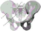
图6是本发明的使用状态图。Fig. 6 is a diagram of the use state of the present invention.
图中标记为:Labeled in the figure:
1、主钉;101、中心通道;102、螺旋刀片;103、内螺纹;104、凹槽;105、卡槽;1. Main nail; 101. Central channel; 102. Spiral blade; 103. Internal thread; 104. Groove; 105. Card slot;
2、防旋尾卡;201、通孔;202、卡销;2. Anti-rotation tail clip; 201, through hole; 202, bayonet pin;
3、调节螺栓;301、螺帽;302、螺杆;303、工具孔;3. Adjusting bolt; 301, nut; 302, screw; 303, tool hole;
4、髂骨;5、骶骨。4. Ilium; 5. Sacrum.
具体实施方式Detailed ways
在本发明的描述中,需要说明的是,术语“正面”、“上”、“下”、“左”、“右”、“竖直”、“水平”等指示的方位或位置关系为基于附图所示的方位或位置关系,仅是为了便于描述本发明和简化描述,而不是指示或暗示所指的装置或元件必须具有特定的方位、以特定的方位构造和操作,因此不能理解为对本发明的限制。In the description of the present invention, it should be noted that the orientation or positional relationship indicated by the terms "front", "upper", "lower", "left", "right", "vertical", "horizontal" etc. are based on The orientation or positional relationship shown in the drawings is only for the convenience of describing the present invention and simplifying the description, and does not indicate or imply that the referred device or element must have a specific orientation, be constructed and operated in a specific orientation, and therefore cannot be understood as Limitations on the Invention.
在本发明的描述中,需要说明的是,除非另有明确的规定和限定,术语“安装”、“相连”、“连接”应做广义理解,例如,可以是固定连接,也可以是可拆卸连接,或一体地连接;可以是直接相连,也可以通过中间媒介间接相连,可以是两个元件内部的连通。对于本领域的普通技术人员而言,可以具体情况理解上述术语在本发明中的具体含义。In the description of the present invention, it should be noted that unless otherwise specified and limited, the terms "installation", "connection" and "connection" should be understood in a broad sense, for example, it can be a fixed connection or a detachable connection. Connected, or integrally connected; it can be directly connected, or indirectly connected through an intermediary, and it can be the internal communication of two elements. Those of ordinary skill in the art can understand the specific meanings of the above terms in the present invention in specific situations.
下面结合附图对本发明进一步说明。The present invention will be further described below in conjunction with the accompanying drawings.
实施例一Embodiment one
参照图1,本发明的用于松质骨的强力拉力钉,包括主钉1和连接在主钉1顶端的尾套,主钉1为柱状结构,主钉1内沿主钉1轴向贯穿的布置有用于克氏针通过的中心通道101,主钉1靠近底端的侧面设置有螺旋刀片102。手术时,利用克氏针定位,通过C臂显影,确定拉力钉的置入位置,再将主钉的中心通道穿过克氏针,敲入主钉,由于主钉的底端设置有螺旋刀片,因此主钉在敲入的过程随螺旋刀片的螺旋纹路旋转缓慢进入骨组织,待主钉置入到预定部位后,拔出克氏针,将尾套与主钉相连即可。可见,相比于传统螺纹方式的拉力钉而言,本发明通过在主钉的底端设置螺旋刀片来替代传统的螺纹。首先,螺旋刀片具有刃口,可切割骨组织,降低螺旋刀片与骨组织之间的摩擦力,使主钉更加顺畅的置入到骨组织中,降低了手术操作的困难,提高手术效率;而且螺旋进入方式能最小程度破坏骨组织;其次,由于螺纹刀片为螺旋状,因此可以起到很好的限位作用,能很好的限制骨组织内的主钉在横向和竖向两个方向上转动;再者,相较于螺纹方式而言,螺旋刀片的吃骨量更大,与骨组织之间的接触面积更广,拉扯骨组织的力量更强,与骨组织之间固定更牢,从而保证骨折部位相邻的骨组织贴合更紧密,有利于患者骨折部位骨组织的后期恢复,能有效缩短患者的康复期。Referring to Fig. 1, the strong tensile nail for cancellous bone of the present invention includes a
螺旋刀片的螺旋角β不能过大,也不能过小。螺旋角β过大,螺旋刀片102就会较为笔直,主钉在骨组织中就不能起到很好的限位作用,主钉在纵向上有位移的风险;螺旋角β设置过小,螺旋刀片102较为弯曲且纹路较多,就会增加了主钉的置入困难,而且破坏的骨组织就较多。参照图3,因此本实施例优选的螺旋角β为70°。The helix angle β of the helical blade cannot be too large or too small. If the helix angle β is too large, the
本实施例中的螺旋刀片102与主钉1采用一体成型的工艺,增强螺旋刀片与主钉连接的稳定性,降低两者断裂的风险,可直接上机床在主钉上铣出螺旋刀片。In this embodiment, the
参照图1和图2,本实施例在中心通道101内靠近主钉1顶部的一端设置有内螺纹103;所述尾套包括防旋尾卡2和调节螺栓3,防旋尾卡2为柱状结构,防旋尾卡2内沿防旋尾卡2轴向布置有通孔201,调节螺栓3包括螺帽301和螺杆302,调节螺栓3穿过防旋尾卡的通孔201与主钉1螺纹连接。这也是本发明设计的巧妙之处,本发明的调节螺栓穿过防旋尾卡的通孔与主钉螺纹连接,也就是说,通过拧动调节螺栓可拉紧主钉与防旋尾卡,换句话说,通过拧动螺栓可将主钉拉向防旋尾卡移动。当主钉穿过正常骨组织与骨折部位的骨组织后,动过拧动螺栓将骨折部位的骨组织拉向正常的骨组织,使两块骨组织逐渐靠拢,减少两块骨组织之间的间隙,使两块骨组织贴合更加紧密,从而有利于患者骨折部位骨组织的后期恢复,能有效缩短患者的康复期。综上,本发明通过调节螺栓可调节主钉的拉力,也就是调节相邻两块骨组织之间的间隙,使两块骨组织的贴合程度最佳,从而有利于患者骨折部位骨组织的后期恢复。Referring to Fig. 1 and Fig. 2, in this embodiment, an
参照图2,本实施例还在主钉1的顶部设置有凹槽104,凹槽104的直径大于防旋尾卡2的外径,防旋尾卡2嵌入式的布置在主钉的凹槽104内;在完成拉力钉的置入后,防旋尾卡2的顶部与骨组织表面齐平。将防旋尾卡嵌入式的布置在主钉的凹槽内,一方面能有效缩短拉力钉的总长度,避免拉力钉过度置入骨组织,损伤骨组织;另一方面,将防旋尾卡隐藏在凹槽内,避免单独设置的防旋尾卡在骨组织中转动,从而影响拉力钉的固定效果。防旋尾卡置入骨组织过深不便于后期拉力钉的取出;防旋尾卡裸露在骨组织表面,会给患者来带异物感,带来不适。为此本发明设计防旋尾卡的顶部与骨组织表面齐平,使患者没有异物感,不会给患者带来不适感。Referring to Fig. 2, this embodiment is also provided with a
参照图2和图4,本实施例中螺帽301的直径小于通孔201的内径,螺帽301可拧入到防旋尾卡2内;所述螺帽301的顶部设置有工具孔303。螺帽采用沉头的方式与防旋尾卡相连,避免螺帽凸出防旋尾卡表面,也就避免螺帽凸出骨组织表面,避免给患者来带异物感,带来不适。工具孔的设置便有医护人员通过采用辅助工具拧动调节螺栓,比如本申请的工具孔为内六角空,医护人员可以采用对应的内六角扳手。2 and 4, the diameter of the
参照图4和图5,本实施例中的通孔201为锥形,螺帽301为与凹槽104匹配的形状。锥形的通孔具有一定的导向作用,螺帽在靠近通孔的过程中,逐渐与通孔贴合,是两者贴合更加紧密,避免骨组织的长入,同时有降低了安装难度。Referring to FIG. 4 and FIG. 5 , the through
本实施例中主钉1和尾套由医用钛合金,具有较高强度以及较佳的防水性和防锈蚀性。In this embodiment, the
实施例二Embodiment two
参照图1和图4,在实施例一的基础上,本实施在凹槽104内沿凹槽径向布置有两个卡槽105,防旋尾卡2上设置有与卡槽105匹配的两个卡销202,卡销202延伸至卡槽105外部。卡销的设置也是本发明的巧妙之处,由于卡销设置在防旋尾卡的外壁,因此使得防旋尾卡的整体外形不再是圆柱状。因为柱状的结构与骨组织相连容易产生自旋,也就是自动转动,主钉自旋后其拉扯力就减弱,不利于骨组织的愈合以及康复。为此,本申请在设置在防旋尾卡外壁的卡销改变了防旋尾卡的整体外形,卡销能起到很好的限位作用,避免主钉随防旋尾卡同步在骨组织内自旋,保证骨折部位骨组织之间连接的稳定性,有利于患者骨折部位骨组织的后期恢复。Referring to Fig. 1 and Fig. 4, on the basis of the first embodiment, in this implementation, two
参照图4,本实施例中的卡销202设计为杯把形的板状结构,卡销较为圆滑,避免尖刺的结构损伤骨组织。Referring to FIG. 4 , the
实施例三Embodiment three
参照图6,本实施例以治疗单侧不稳定骨盆后环损伤为例,介绍本发明拉力钉的使用方法。胫骨盆中含有髂骨4和骶骨5,以修复和治疗骶骨5为例,具体步骤为:Referring to Fig. 6, this embodiment takes the treatment of unilateral unstable posterior pelvic ring injury as an example, and introduces the use method of the tension nail of the present invention. The tibial pelvis contains
一、骨盆后侧入路,利用克氏针定位,通过C臂显影,确定拉力钉的置入位置;1. Posterior approach to the pelvis, using Kirschner wire positioning, and C-arm imaging to determine the placement position of the tension nail;
二、将主钉的中心通道穿过克氏针,缓慢敲打主钉,由于主钉的底端设置有螺旋刀片,因此主钉在敲入的过程随螺旋刀片的螺旋纹路旋转缓慢进入骨组织;2. Pass the central channel of the main nail through the Kirschner wire, and slowly tap the main nail. Since the bottom of the main nail is provided with a helical blade, the main nail slowly enters the bone tissue as it rotates along the spiral pattern of the helical blade during the knock-in process;
三、主钉穿过骶骨4并进入髂骨5,待主钉置入到预定部位后,拔出克氏针;3. The main nail passes through the
四、在主钉顶部的凹槽内安装防旋尾卡,并保证防旋尾卡的卡销处于凹槽的卡槽内,防旋尾卡完全沉入到凹槽内,再拧入调节螺栓,调节螺栓一方面可以固定主钉、防旋尾卡和髂骨;另一方面可将主钉拉向防旋尾卡,也就是将骶骨拉向髂骨;医护人员通过显影设备观察髂骨与骶骨之间的距离,当两者达到合适距离后停止拧动调节螺栓,调节螺栓提供拉力将骶骨和髂骨拉紧,从而实现治疗作用。4. Install the anti-rotation tail card in the groove on the top of the main nail, and ensure that the bayonet pin of the anti-rotation tail card is in the groove of the groove, and the anti-rotation tail card is completely sunk into the groove, and then screw in the adjusting bolt On the one hand, the adjusting bolt can fix the main nail, the anti-rotation tail clip and the ilium; The distance between the sacrum, when the two reach the appropriate distance, stop turning the adjustment bolt, and the adjustment bolt provides tension to tighten the sacrum and iliac bone, so as to achieve the therapeutic effect.
实施例四Embodiment four
本发明的拉力钉除了能修复治疗实施例三的单侧不稳定骨盆后环损伤以外,还可用于治疗胫骨近端骨折,胫骨近端靠近膝关节,内部松质骨占比大,具体操作方法与实施例三相同,调节螺栓提供拉力将骨折块和胫骨拉紧在一起,实现骨折治疗。In addition to repairing the unilateral unstable posterior pelvic ring injury in Example 3, the tensile nail of the present invention can also be used to treat proximal tibia fractures. The proximal tibia is close to the knee joint, and the internal cancellous bone accounts for a large proportion. The specific operation method Same as the third embodiment, the adjusting bolt provides tension to pull the fracture block and the tibia together to achieve fracture treatment.
以上所述的具体实施方式,对本发明的目的、技术方案和有益效果进行了进一步详细说明,所应理解的是,以上所述仅为本发明的具体实施方式而已,并不用于限定本发明的保护范围,凡在本发明的精神和原则之内,所做的任何修改、等同替换、改进等,均应包含在本发明的保护范围之内。The specific embodiments described above have further described the purpose, technical solutions and beneficial effects of the present invention in detail. It should be understood that the above descriptions are only specific embodiments of the present invention and are not intended to limit the scope of the present invention. Protection scope, within the spirit and principles of the present invention, any modification, equivalent replacement, improvement, etc., shall be included in the protection scope of the present invention.
Claims (10)
Priority Applications (1)
| Application Number | Priority Date | Filing Date | Title |
|---|---|---|---|
| CN202211582022.4ACN115770092A (en) | 2022-12-09 | 2022-12-09 | Strong tension nail for cancellous bone |
Applications Claiming Priority (1)
| Application Number | Priority Date | Filing Date | Title |
|---|---|---|---|
| CN202211582022.4ACN115770092A (en) | 2022-12-09 | 2022-12-09 | Strong tension nail for cancellous bone |
Publications (1)
| Publication Number | Publication Date |
|---|---|
| CN115770092Atrue CN115770092A (en) | 2023-03-10 |
Family
ID=85392251
Family Applications (1)
| Application Number | Title | Priority Date | Filing Date |
|---|---|---|---|
| CN202211582022.4AWithdrawnCN115770092A (en) | 2022-12-09 | 2022-12-09 | Strong tension nail for cancellous bone |
Country Status (1)
| Country | Link |
|---|---|
| CN (1) | CN115770092A (en) |
Cited By (1)
| Publication number | Priority date | Publication date | Assignee | Title |
|---|---|---|---|---|
| WO2024213280A1 (en)* | 2023-04-13 | 2024-10-17 | Ulrich Gmbh & Co. Kg | Bone anchor, and kit having a bone achor for positioning a reference marker |
- 2022
- 2022-12-09CNCN202211582022.4Apatent/CN115770092A/ennot_activeWithdrawn
Cited By (1)
| Publication number | Priority date | Publication date | Assignee | Title |
|---|---|---|---|---|
| WO2024213280A1 (en)* | 2023-04-13 | 2024-10-17 | Ulrich Gmbh & Co. Kg | Bone anchor, and kit having a bone achor for positioning a reference marker |
Similar Documents
| Publication | Publication Date | Title |
|---|---|---|
| US10441334B2 (en) | Minimal incision removable bone screw | |
| US8911443B2 (en) | Plate holder for manipulating bone plate | |
| US20060036248A1 (en) | Fixation elements | |
| EP2185087A2 (en) | Bone plates and bone plate assemblies | |
| BR112012002215B1 (en) | HUMAN HEAD FIXATION DEVICE FOR BONES WITH OSTEOPOROSIS. | |
| CN202235646U (en) | Proximal femur dissection locking plate | |
| CN115770092A (en) | Strong tension nail for cancellous bone | |
| CN204797979U (en) | Intramedullary fixing device for proximal femoral fracture | |
| CN110279447A (en) | A kind of Combined spiral enhanced type bone anchors | |
| CN211633533U (en) | Blunt-end pedicle screw for spinal surgery | |
| CN111568522A (en) | A tension trabecular reconstruction type intramedullary nail fixation device for proximal femur | |
| CN215192132U (en) | A novel proximal femoral intramedullary fixation system | |
| CN207024107U (en) | A kind of intertrochanteric fracture Medullary fixation system | |
| CN101953712B (en) | Semi-self-locking acetabulum posterior wall and posterior column anatomical plate | |
| CN108210047B (en) | Proximal femoral fracture intramedullary fixation device | |
| CN208741123U (en) | A kind of distal tibial rear side lockplate | |
| CN201414836Y (en) | Lockplate for proximal end of femoral bones | |
| CN208404803U (en) | A kind of interlocking anti-settling proximal femoral nail | |
| CN205031357U (en) | Immediately, hip screw pulling force screw for steel sheet pressurizes | |
| CN218636063U (en) | Anterior column intramedullary nail | |
| CN220608391U (en) | Femoral neck power cross nail plate system | |
| RU2826771C1 (en) | Minimally invasive method of osteosynthesis of medial fractures of femoral neck | |
| CN209678659U (en) | A kind of guiding locked pressurized bone plate | |
| CN209032601U (en) | A safe fixation component for preventing displacement of bone cement mass after vertebral augmentation | |
| CN208319301U (en) | a spinal fixation nail |
Legal Events
| Date | Code | Title | Description |
|---|---|---|---|
| PB01 | Publication | ||
| PB01 | Publication | ||
| SE01 | Entry into force of request for substantive examination | ||
| SE01 | Entry into force of request for substantive examination | ||
| WW01 | Invention patent application withdrawn after publication | ||
| WW01 | Invention patent application withdrawn after publication | Application publication date:20230310 |