CN115768357A - Parallel path piercing device guide and method - Google Patents
Parallel path piercing device guide and methodDownload PDFInfo
- Publication number
- CN115768357A CN115768357ACN202180043258.8ACN202180043258ACN115768357ACN 115768357 ACN115768357 ACN 115768357ACN 202180043258 ACN202180043258 ACN 202180043258ACN 115768357 ACN115768357 ACN 115768357A
- Authority
- CN
- China
- Prior art keywords
- syringe
- needle
- guide
- guide plate
- tip
- Prior art date
- Legal status (The legal status is an assumption and is not a legal conclusion. Google has not performed a legal analysis and makes no representation as to the accuracy of the status listed.)
- Pending
Links
Images


Classifications
- A—HUMAN NECESSITIES
- A61—MEDICAL OR VETERINARY SCIENCE; HYGIENE
- A61B—DIAGNOSIS; SURGERY; IDENTIFICATION
- A61B8/00—Diagnosis using ultrasonic, sonic or infrasonic waves
- A61B8/08—Clinical applications
- A61B8/0833—Clinical applications involving detecting or locating foreign bodies or organic structures
- A61B8/0841—Clinical applications involving detecting or locating foreign bodies or organic structures for locating instruments
- A—HUMAN NECESSITIES
- A61—MEDICAL OR VETERINARY SCIENCE; HYGIENE
- A61B—DIAGNOSIS; SURGERY; IDENTIFICATION
- A61B8/00—Diagnosis using ultrasonic, sonic or infrasonic waves
- A61B8/08—Clinical applications
- A61B8/0833—Clinical applications involving detecting or locating foreign bodies or organic structures
- A61B8/085—Clinical applications involving detecting or locating foreign bodies or organic structures for locating body or organic structures, e.g. tumours, calculi, blood vessels, nodules
- A—HUMAN NECESSITIES
- A61—MEDICAL OR VETERINARY SCIENCE; HYGIENE
- A61B—DIAGNOSIS; SURGERY; IDENTIFICATION
- A61B8/00—Diagnosis using ultrasonic, sonic or infrasonic waves
- A61B8/12—Diagnosis using ultrasonic, sonic or infrasonic waves in body cavities or body tracts, e.g. by using catheters
- A—HUMAN NECESSITIES
- A61—MEDICAL OR VETERINARY SCIENCE; HYGIENE
- A61B—DIAGNOSIS; SURGERY; IDENTIFICATION
- A61B8/00—Diagnosis using ultrasonic, sonic or infrasonic waves
- A61B8/42—Details of probe positioning or probe attachment to the patient
- A61B8/4209—Details of probe positioning or probe attachment to the patient by using holders, e.g. positioning frames
- A61B8/4218—Details of probe positioning or probe attachment to the patient by using holders, e.g. positioning frames characterised by articulated arms
- A—HUMAN NECESSITIES
- A61—MEDICAL OR VETERINARY SCIENCE; HYGIENE
- A61B—DIAGNOSIS; SURGERY; IDENTIFICATION
- A61B8/00—Diagnosis using ultrasonic, sonic or infrasonic waves
- A61B8/44—Constructional features of the ultrasonic, sonic or infrasonic diagnostic device
- A61B8/4444—Constructional features of the ultrasonic, sonic or infrasonic diagnostic device related to the probe
- A61B8/4455—Features of the external shape of the probe, e.g. ergonomic aspects
- A—HUMAN NECESSITIES
- A61—MEDICAL OR VETERINARY SCIENCE; HYGIENE
- A61M—DEVICES FOR INTRODUCING MEDIA INTO, OR ONTO, THE BODY; DEVICES FOR TRANSDUCING BODY MEDIA OR FOR TAKING MEDIA FROM THE BODY; DEVICES FOR PRODUCING OR ENDING SLEEP OR STUPOR
- A61M5/00—Devices for bringing media into the body in a subcutaneous, intra-vascular or intramuscular way; Accessories therefor, e.g. filling or cleaning devices, arm-rests
- A61M5/42—Devices for bringing media into the body in a subcutaneous, intra-vascular or intramuscular way; Accessories therefor, e.g. filling or cleaning devices, arm-rests having means for desensitising skin, for protruding skin to facilitate piercing, or for locating point where body is to be pierced
- A61M5/427—Locating point where body is to be pierced, e.g. vein location means using ultrasonic waves, injection site templates
- A—HUMAN NECESSITIES
- A61—MEDICAL OR VETERINARY SCIENCE; HYGIENE
- A61B—DIAGNOSIS; SURGERY; IDENTIFICATION
- A61B17/00—Surgical instruments, devices or methods
- A61B17/34—Trocars; Puncturing needles
- A61B17/3403—Needle locating or guiding means
- A—HUMAN NECESSITIES
- A61—MEDICAL OR VETERINARY SCIENCE; HYGIENE
- A61B—DIAGNOSIS; SURGERY; IDENTIFICATION
- A61B17/00—Surgical instruments, devices or methods
- A61B17/34—Trocars; Puncturing needles
- A61B17/3403—Needle locating or guiding means
- A61B2017/3405—Needle locating or guiding means using mechanical guide means
- A—HUMAN NECESSITIES
- A61—MEDICAL OR VETERINARY SCIENCE; HYGIENE
- A61B—DIAGNOSIS; SURGERY; IDENTIFICATION
- A61B17/00—Surgical instruments, devices or methods
- A61B17/34—Trocars; Puncturing needles
- A61B17/3403—Needle locating or guiding means
- A61B2017/3413—Needle locating or guiding means guided by ultrasound
- A—HUMAN NECESSITIES
- A61—MEDICAL OR VETERINARY SCIENCE; HYGIENE
- A61M—DEVICES FOR INTRODUCING MEDIA INTO, OR ONTO, THE BODY; DEVICES FOR TRANSDUCING BODY MEDIA OR FOR TAKING MEDIA FROM THE BODY; DEVICES FOR PRODUCING OR ENDING SLEEP OR STUPOR
- A61M5/00—Devices for bringing media into the body in a subcutaneous, intra-vascular or intramuscular way; Accessories therefor, e.g. filling or cleaning devices, arm-rests
- A61M5/46—Devices for bringing media into the body in a subcutaneous, intra-vascular or intramuscular way; Accessories therefor, e.g. filling or cleaning devices, arm-rests having means for controlling depth of insertion
Landscapes
- Health & Medical Sciences (AREA)
- Life Sciences & Earth Sciences (AREA)
- Public Health (AREA)
- Veterinary Medicine (AREA)
- General Health & Medical Sciences (AREA)
- Engineering & Computer Science (AREA)
- Biomedical Technology (AREA)
- Heart & Thoracic Surgery (AREA)
- Animal Behavior & Ethology (AREA)
- Surgery (AREA)
- Nuclear Medicine, Radiotherapy & Molecular Imaging (AREA)
- Pathology (AREA)
- Medical Informatics (AREA)
- Molecular Biology (AREA)
- Radiology & Medical Imaging (AREA)
- Physics & Mathematics (AREA)
- Biophysics (AREA)
- Vascular Medicine (AREA)
- Anesthesiology (AREA)
- Hematology (AREA)
- Dermatology (AREA)
- Infusion, Injection, And Reservoir Apparatuses (AREA)
- Ultra Sonic Daignosis Equipment (AREA)
- Prostheses (AREA)
- Paper (AREA)
- Measurement Of The Respiration, Hearing Ability, Form, And Blood Characteristics Of Living Organisms (AREA)
Abstract
Description
Translated fromChinese技术领域technical field
本发明涉及与医学成像仪器一起使用的穿刺装置引导装置,更具体地涉及用于相对于医学成像仪器探头将穿刺装置引导至患者身上的可重复位置的装置。更具体地,本发明涉及一种穿刺装置引导件,包括:适配器,其配置为固定地附接到超声探头;注射器支架组件,其配置为可滑动地连接到适配器并在其中容纳注射器;其中,注射器支架组件配置为相对于超声探头在轴向方向上在探头适配器上滑动;其中,注射器支架组件配置为允许选择性地调节注射器针路径相对于超声探头的径向距离;其中适配器包括尖端引导件以选择性地将针的远端与路径的径向距离对准;并且其中,当超声探头插入到患者体内时,注射器组件配置为在适配器上向前滑动以将针穿过针尖引导器插入到患者内。本发明还涉及一种执行注射的方法,特别是通过使用根据本发明的穿刺装置引导件,以及一种构造成与根据本发明的穿刺装置引导件一起使用的引导板。因此,提供了一种引导装置,用于便于将穿刺装置(针)放置在相对于超声探头的限定位置处。引导装置在针注射部位附近提供针尖的额外支撑件,以在整个注射过程中保持选定的路径。额外的支撑件会自动缩回,以便在注射后对用过的注射器进行简单处理。该引导装置最大限度地减少了与污染部件的接触,并能够在不从患者身上移除超声探头的情况下,为多次不同的注射实现注射器的插入、对齐和移除。The present invention relates to a lancing device guide for use with a medical imaging instrument, and more particularly to an arrangement for guiding a lancing device to a repeatable position on a patient relative to a medical imaging instrument probe. More specifically, the present invention relates to a piercing device guide comprising: an adapter configured to be fixedly attached to an ultrasound probe; a syringe holder assembly configured to slidably connect to the adapter and accommodate a syringe therein; wherein, The syringe holder assembly is configured to slide on the probe adapter in an axial direction relative to the ultrasound probe; wherein the syringe holder assembly is configured to allow selective adjustment of a radial distance of the syringe needle path relative to the ultrasound probe; wherein the adapter includes a tip guide to selectively align the distal end of the needle with a radial distance of the path; and wherein, when the ultrasound probe is inserted into the patient, the syringe assembly is configured to slide forward on the adapter to insert the needle through the needle tip guide into inside the patient. The invention also relates to a method of performing an injection, in particular by using a piercing device guide according to the invention, and a guide plate configured for use with the piercing device guide according to the invention. Thus, a guide is provided for facilitating the placement of the piercing device (needle) at a defined position relative to the ultrasound probe. The guide provides additional support for the needle tip near the needle injection site to maintain the selected path throughout the injection. The extra support retracts automatically for easy disposal of the used syringe after injection. The guide minimizes contact with contaminated parts and enables syringe insertion, alignment, and removal for multiple different injections without removing the ultrasound probe from the patient.
背景技术Background technique
超声探头等成像仪器彻底改变了许多重要医疗手术的执行方式。这些医疗仪器利用成像技术来探索和评估人体组织和/或器官的状况。因此,已经开发出诊断和治疗方案,该方案允许在对患者造成最小干扰的情况下执行许多非常成功和安全的手术。例如,超声探头已成为一种可接受的方式,用于探索人类和动物的内腔,例如消化道和生殖道,以便进行常规检查,以及成为识别肿瘤或其他目标组织区域的证据。Imaging instruments such as ultrasound probes have revolutionized the way many important medical procedures are performed. These medical instruments utilize imaging technology to explore and assess the condition of human tissues and/or organs. Consequently, diagnostic and therapeutic protocols have been developed that allow many very successful and safe procedures to be performed with minimal disturbance to the patient. For example, ultrasound probes have become an accepted way to explore the internal cavities of humans and animals, such as the digestive and reproductive tracts, for routine examinations, as well as for identifying tumors or other areas of evidence of interest.
当在对象的组织内移动穿刺装置时,穿刺装置引导件需要允许精确引导穿刺装置。由于穿刺装置,例如用于穿刺组织的插管(空心针),大多设计为具有不对称的斜面和锋利的边缘,穿刺装置在组织内的切口和移动导致穿刺装置不仅在其被推动的轴上移动。沿斜面不均匀地产生的摩擦阻力导致针也在其他方向上移动。同时补偿这种运动的穿刺装置导向器是需要的。The piercing device guide needs to allow precise guidance of the piercing device when moving the piercing device within the tissue of the subject. Since puncture devices, such as cannula (hollow needles) used to puncture tissue, are mostly designed with asymmetrical bevels and sharp edges, the incision and movement of the puncture device in the tissue causes the puncture device not only on the axis on which it is pushed move. Frictional resistance created unevenly along the ramp causes the needle to move in other directions as well. A piercing device guide that also compensates for this movement is needed.
WO2021067734公开了一种与超声探头一起使用并用于引导穿刺装置的装置。然而,该装置具有缺点,即穿刺装置(例如针或插管)的尖端不够稳定,无法补偿因在组织内移动不对称斜面针而产生的力,因此可能导致穿刺装置在对象内的运动不准确。此外,该装置可能会意外地被推入患者的内腔,从而导致该装置受到污染并可能损坏患者的组织。如果设备被污染,例如由于直肠腔内的粪便,并且穿刺器由于反复引导而导致接触到污染区域,穿刺器在穿刺患者组织时存在感染患者的风险。这种风险只能通过在同一患者重复使用期间更换和/或清洁(例如消毒)设备来避免。WO2021067734 discloses a device for use with an ultrasound probe and for guiding a piercing device. However, this device has the disadvantage that the tip of the piercing device (such as a needle or cannula) is not stable enough to compensate for the forces generated by moving the asymmetrically beveled needle within the tissue, thus potentially resulting in inaccurate movement of the piercing device within the subject . Additionally, the device may be accidentally pushed into the patient's lumen, resulting in contamination of the device and possible damage to the patient's tissue. If the device is contaminated, for example by feces in the rectal lumen, and the trocar touches the contaminated area due to repeated guidance, there is a risk of infecting the patient when the trocar pierces the patient's tissue. This risk can only be avoided by changing and/or cleaning (eg, sterilizing) equipment between repeated uses on the same patient.
EP2170440A2公开了一种与医疗器械一起使用并用于引导穿刺装置的注射装置。该装置包括引导管,其中穿刺装置装配成当穿刺和/或在受试者的组织内移动时不能自由移动。然而,当从穿刺装置导向装置中取出穿刺装置时,需要通过导管将穿刺装置拉回,从而使附着在导管内部的穿刺装置导向装置针尖或穿刺装置的组织和污染物质(例如,粪便)沉积。通过沿着导管推动另一个穿刺装置来重复使用该装置会导致沉积的材料粘在穿刺装置上并在穿透对象的表面时被输送到对象中。这可能导致该对象的组织感染和/或炎症,这需要避免。此外,该装置可能会被意外地推入患者的内腔,从而导致该装置受到污染并可能损坏患者的组织。如果设备被污染,例如被直肠腔内的粪便污染,穿刺装置的反复引导会导致穿刺装置接触污染区域,从而在穿刺装置穿透患者组织时增加感染患者的风险。这种风险只能通过在同一患者重复使用期间更换和/或清洁(例如消毒)设备来避免。因此,只能通过清洁设备或使用新设备来促进使用EP2170440A2的设备进行重复准确注射。EP2170440A2 discloses an injection device for use with a medical instrument and for guiding a piercing device. The device includes a guide tube, wherein the piercing device is assembled so as not to move freely while piercing and/or moving within the tissue of the subject. However, when the puncture device is removed from the puncture device guide, the puncture device needs to be pulled back through the catheter, thereby depositing tissue and contaminants (eg, feces) attached to the needle tip of the puncture device guide or the puncture device inside the catheter. Reusing the device by pushing another piercing device along the catheter can cause deposited material to stick to the piercing device and be transported into the subject as it penetrates the surface of the subject. This could lead to infection and/or inflammation of the subject's tissues, which needs to be avoided. Additionally, the device may be accidentally pushed into the patient's lumen, resulting in contamination of the device and possible damage to the patient's tissue. If the device becomes contaminated, for example by feces within the rectal lumen, repeated guidance of the piercing device can cause the piercing device to contact the contaminated area, thereby increasing the risk of infecting the patient as the piercing device penetrates patient tissue. This risk can only be avoided by changing and/or cleaning (eg, sterilizing) equipment between repeated uses on the same patient. Therefore, repeated accurate injections using the device of EP2170440A2 can only be facilitated by cleaning the device or using a new device.
上述公开内容均未公开穿刺装置引导件,其用于在患者身上和/或体内特定位置注射的穿刺装置的准确且安全的可重复引导。None of the above publications discloses a puncture device guide for accurate and safe repeatable guidance of a puncture device for injection on a patient and/or at a specific location in the body.
发明内容Contents of the invention
本发明是鉴于上述现有技术而作出的。因此,本发明的目的是提供与医学成像仪器一起使用的穿刺装置引导装置,更具体地,提供用于相对于医学成像仪器探头将穿刺装置准确且可重复地引导至患者身上和/或体内的位置的装置。本发明要解决的另一个问题是提供一种与医学成像仪器一起使用的穿刺装置引导装置,该穿刺装置引导装置可重复地允许相对于医学成像探头将穿刺装置准确且安全地引导至患者身上和/或体内的位置。本发明要解决的另一个问题是提供这样一种装置,该装置减少、最小化或消除意外将装置推入患者内腔的风险。本发明要解决的另一个问题是提供这样一种装置,其降低、最小化或消除污染穿刺/注射部位的风险,特别是如果该装置用于重复使用。本发明要解决的另一个问题是提供这样的装置,其减少、最小化或消除清洁(例如消毒)或在同一患者重复使用之间更换装置的需要。The present invention has been made in view of the prior art described above. Accordingly, it is an object of the present invention to provide a puncture device guide for use with a medical imaging instrument, and more particularly, to provide a device for accurately and repeatably guiding a puncture device onto and/or within a patient relative to a medical imaging instrument probe. location device. Another problem to be solved by the present invention is to provide a puncture device guide for use with a medical imaging instrument which repeatably allows accurate and safe guidance of the puncture device on the patient relative to the medical imaging probe and /or location in the body. Another problem to be solved by the present invention is to provide a device which reduces, minimizes or eliminates the risk of accidentally pushing the device into the lumen of the patient. Another problem to be solved by the present invention is to provide a device which reduces, minimizes or eliminates the risk of contamination of the puncture/injection site, especially if the device is intended for repeated use. Another problem to be solved by the present invention is to provide a device which reduces, minimizes or eliminates the need for cleaning (eg disinfection) or replacement of the device between re-uses on the same patient.
该目的由权利要求中定义的主题解决。This object is solved by the subject-matter defined in the claims.
本发明优于现有技术,因为降低了穿刺装置引导件意外进入内腔从而被污染和/或伤害患者的风险。此外,本发明的优点在于以更高的精度引导穿刺装置。此外,本发明的穿刺装置引导件具有当穿刺装置与其一起使用时不会被污染(例如,被粪便污染)的优点,该穿刺装置本身在使用期间被污染。因此,当用于同一患者时,本发明的穿刺装置引导件不必在不同穿刺装置的重复引导之间更换或清洁。此外,穿刺装置无污染引导的特点可以与穿刺装置在患者组织内的高精度移动相结合。此外,穿刺装置引导件被设计成特别适用于将针注射和/或将组合物和/或物质施用到肛门括约肌装置中以预防和/或治疗肛门失禁。The present invention is superior to the prior art in that the risk of a piercing device guide accidentally entering the lumen, contaminating it and/or injuring the patient is reduced. Furthermore, the invention has the advantage that the piercing device is guided with greater precision. Furthermore, the piercing device guide of the present invention has the advantage that it does not become contaminated (eg by faeces) when a piercing device is used therewith, the piercing device itself becoming soiled during use. Thus, the piercing device guide of the present invention does not have to be replaced or cleaned between repeated guidance of different piercing devices when used on the same patient. Furthermore, the contamination-free guidance of the puncture device can be combined with high-precision movement of the puncture device within the patient's tissue. Furthermore, the piercing device guide is designed to be particularly suitable for needle injection and/or application of compositions and/or substances into the anal sphincter device for the prevention and/or treatment of anal incontinence.
附图说明Description of drawings
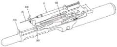
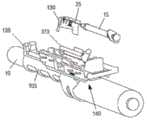
图1是与本文描述的实施例一致的与超声探头一起使用的针引导装置的一个实施例的立体图;1 is a perspective view of one embodiment of a needle guide device for use with an ultrasound probe consistent with embodiments described herein;
图2A和图2B分别是装配图和立体图,展示了图1的探头和探头适配器的连接;Fig. 2A and Fig. 2B are assembly drawing and three-dimensional view respectively, have demonstrated the connection of probe and probe adapter of Fig. 1;
图3是图1的注射器支架组件的立体图;Figure 3 is a perspective view of the syringe holder assembly of Figure 1;
图4A和图4B是侧视图和后视图,示出了图1的注射器支架组件和探头适配器的连接;4A and 4B are side and rear views illustrating the connection of the syringe holder assembly and probe adapter of FIG. 1;
图5A和图5B分别是图3的注射器支架组件相对于图2B的探头适配器处于升高和降低配置的立体图;5A and 5B are perspective views, respectively, of the syringe holder assembly of FIG. 3 in raised and lowered configurations relative to the probe adapter of FIG. 2B;
图6A和图6B是示出与图1的针引导板接合的注射器的侧视和后视立体图。6A and 6B are side and rear perspective views showing the syringe engaged with the needle guide plate of FIG. 1 .
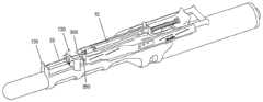
图7A-7C是示出图6A和6B的注射器和针导板与图5A的注射器支架组件和探针适配器的附接的立体图;7A-7C are perspective views illustrating the attachment of the syringe and needle guide of FIGS. 6A and 6B to the syringe holder assembly and stylet adapter of FIG. 5A;
图8A和8B是说明在注射过程中针引导装置和注射器的位置的立体图;8A and 8B are perspective views illustrating the position of the needle guide and syringe during an injection;
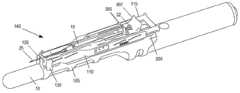
图9A和9B是示出针引导装置和注射器在注射之后的缩回位置的立体图;9A and 9B are perspective views showing the retracted position of the needle guide and syringe after injection;
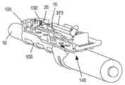
图10A-C是注射器从图1的针引导装置弹出期间的弹出器主体机构的立体图;10A-C are perspective views of the ejector body mechanism during ejection of the syringe from the needle guide of FIG. 1;
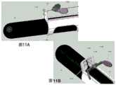
图11A和图11B是侧视图和后透视图,示出了针引导板和探头适配器的另一实施例的对准;11A and 11B are side and rear perspective views illustrating the alignment of another embodiment of the needle guide plate and probe adapter;
图11C和图11D是侧视图和后透视图,示出了图11A和图11B的针引导板和探头适配器的接合;11C and 11D are side and rear perspective views showing engagement of the needle guide plate and probe adapter of FIGS. 11A and 11B ;
图12和图13是根据本文所述的实施方式使用平行路径穿刺装置引导器执行注射的示例性过程的流程图;以及12 and 13 are flowcharts of an exemplary process for performing an injection using a parallel-path piercing device introducer, according to embodiments described herein; and
图14展示了当偏转针连接到带有引导件(w/)或没有引导件(w/o)的注射器支架组件时力测量的结果。Figure 14 demonstrates the results of force measurements when a deflected needle is attached to a syringe holder assembly with a guide (w/) or without a guide (w/o).
术语和定义Terms and Definitions
如本文所用,术语“注射”优选地指代包括将注射装置例如针引入身体组织而不启动排出过程的过程。As used herein, the term "injection" preferably refers to a procedure comprising introducing an injection device, such as a needle, into body tissue without initiating an expulsion process.
术语“注射器”通常是指包括流体储存器的任何流体输送装置(例如,具有至少一个腔室的注射器主体)。注射器主体可包括一个或多个腔室,其优选为圆柱形。每个腔室优选地适于容纳注射器活塞。通过至少一个注射器活塞在注射器主体中的移动,流体可以通过注射器针头从注射器主体排出。注射器例如可以包括具有单个注射器腔室的注射器主体,注射器针头连接到该注射器腔室并且其中布置有注射器活塞。备选地,注射器可以包括两个或更多个腔室,注射器针头连接到这些腔室并且优选地在每种情况下布置有注射器活塞。在本发明的优选实施例中,注射器另外用作肌电图探针(EMG探针),以传导来自进行注射的组织的电信号。The term "syringe" generally refers to any fluid delivery device (eg, a syringe body having at least one chamber) that includes a fluid reservoir. The syringe body may comprise one or more chambers, which are preferably cylindrical. Each chamber is preferably adapted to accommodate a syringe plunger. Fluid may be expelled from the syringe body through the syringe needle by movement of the at least one syringe piston within the syringe body. The syringe may for example comprise a syringe body having a single syringe chamber to which the syringe needle is connected and in which the syringe plunger is arranged. Alternatively, the syringe may comprise two or more chambers, to which the syringe needle is connected and preferably in each case a syringe plunger is arranged. In a preferred embodiment of the invention, the injector is additionally used as an electromyographic probe (EMG probe) to conduct electrical signals from the injected tissue.
本文所用的术语“注射器针”或“针”优选指的是包括注射套管(空心注射器针)的装置,装置可连接到注射器或不可分离地连接到注射器,或者指的是具有至少一个注射器活塞和至少一个活塞杆的活塞装置。注射器针头优选是直的或弯曲的。它可以具有不同角度的不对称或对称斜面。注射器针头可以由一种或多种材料制成,例如但不限于不锈钢。The term "syringe needle" or "needle" as used herein preferably refers to a device comprising an injection cannula (hollow syringe needle), which is connectable or inseparable to a syringe, or to a device having at least one syringe plunger and at least one piston rod. Syringe needles are preferably straight or curved. It can have asymmetrical or symmetrical slopes at different angles. Syringe needles can be made from one or more materials such as, but not limited to, stainless steel.
本文所用的术语“施用”优选包括注射溶液的排出,该排出通过注射装置将优选药学活性物质和/或组合物的注射溶液释放到人体内的特定部位,特别优选地释放进入或邻近肌肉组织,以提供肛门节制(例如,肛门括约肌装置)。给药过程可以是但不限于静态的,静态即注射装置保持在到达的位置。或者,注射过程是动态的,优选地在于注射装置在施用上述物质期间从患者的组织缩回。本文所用的术语“患者”可与术语“对象”互换使用,其优选指人、动物或哺乳动物。The term "administration" as used herein preferably includes the expulsion of the injection solution, which releases the injection solution, preferably a pharmaceutically active substance and/or composition, through the injection device to a specific site in the human body, particularly preferably into or adjacent to muscular tissue, to provide anal continence (eg, anal sphincter device). The administration process may be, but is not limited to, static, ie the injection device remains in the reached position. Alternatively, the injection procedure is dynamic, preferably in that the injection device is retracted from the patient's tissue during administration of the substance. As used herein, the term "patient" is used interchangeably with the term "subject", which preferably refers to a human, animal or mammal.
本文所用的术语“包含”不应被解释为限于“由...组成”的含义(即排除额外的其他物质的存在)。相反,“包含”意味着可以存在可选的附加物质。术语“包含”包括落入其“由...组成”(即不包括额外其他物质的存在)和“包含但不由...组成”(即需要额外其他物质的存在)范围内的特别设想的实施方案,其中前者更优选。The term "comprising" as used herein should not be construed as being limited to the meaning "consisting of" (ie excluding the presence of additional other substances). In contrast, "comprising" means that optional additional materials may be present. The term "comprising" includes those specifically contemplated that fall within its scope of "consisting of" (i.e. excluding the presence of additional other substances) and "comprising but not consisting of" (i.e. requiring the presence of additional other substances) Embodiment, wherein the former is more preferred.
术语“一”、“一个”和“这个”旨在被解释为包括一个或多个项目。此外,除非另有明确说明,否则短语“基于”旨在解释为“至少部分基于”。术语“和/或”旨在解释为包括一个或多个关联项的任何和所有组合。这里使用的“示例性”一词的意思是“作为一个例子”。描述为“示例性”的任何实施例或实施方式不一定被解释为优于或优于其他实施例或实施方式。The terms "a", "an" and "the" are intended to be interpreted as including one or more items. Furthermore, the phrase "based on" is intended to be interpreted as "based at least in part on," unless expressly stated otherwise. The term "and/or" is intended to be interpreted as including any and all combinations of one or more of the associated items. The word "exemplary" is used herein to mean "serving as an example." Any embodiment or implementation described as "exemplary" is not necessarily to be construed as preferred or superior to other embodiments or implementations.
在权利要求中使用诸如“第一”、“第二”、“第三”等顺序术语来修饰权利要求要素本身并不意味着一个权利要求要素相对于另一个权利要求要素的任何优先、优先级或次序,并不意味着方法动作执行的暂时的顺序,也不意味着执行设备执行的指令的时间顺序等,但仅用作标签以区分具有特定名称的一个权利要求元素与具有相同名称的另一个元素(但用于使用序数词)来区分权利要求要素。The use of ordinal terms such as "first," "second," "third," etc. in a claim to modify a claim element does not, by itself, imply any priority, prioritization, of one claim element over another or order, does not imply a temporal order of execution of method actions, nor does it imply a chronological order of instructions executed by an executing device, etc., but is used only as a label to distinguish one claim element with a particular name from another with the same name An element (but used to use ordinal numbers) to distinguish claim elements.
在本申请的描述中使用的任何要素、动作或指令都不应被解释为对本发明是关键的或必需的,除非如此明确描述。此外,如本文所用,冠词“一”旨在包括一个或多个项目。No element, act or instruction used in the description of the application should be construed as critical or essential to the invention unless explicitly described as such. Also, as used herein, the article "a" is intended to include one or more items.
具体实施方式Detailed ways
下面的详细描述参考附图。不同附图中的相同附图标记可以标识相同或相似的元件。此外,以下详细描述不限制本发明。The following detailed description refers to the accompanying drawings. The same reference numbers in different drawings may identify the same or similar elements. Also, the following detailed description does not limit the invention.
本文描述的实施方式涉及用于促进将穿刺装置(例如,针)放置在相对于超声探头的限定位置处的引导装置。如本文所用的术语“引导装置”可与术语“穿刺装置引导件”或“穿刺装置引导装置”互换使用。下面描述的引导装置包括可调节的组件以提供多个彼此相对平行并且在距超声探头的不同限定距离处的路径。因此,这些引导装置允许针路径的径向平移而不改变相对于超声探头的定向角度。然而,尽管提供不同平行路径的改进,针尖在注射点的正确对准仍然是从业者的挑战。Embodiments described herein relate to guide devices for facilitating placement of a puncturing device (eg, a needle) at a defined location relative to an ultrasound probe. As used herein, the term "introducer" may be used interchangeably with the terms "piercing device guide" or "piercing device guide". The guide described below includes an adjustable assembly to provide a plurality of paths relatively parallel to each other and at different defined distances from the ultrasound probe. Thus, these guides allow radial translation of the needle path without changing the angle of orientation relative to the ultrasound probe. However, despite the improvements provided by different parallel paths, proper alignment of the needle tip at the injection site remains a challenge for practitioners.
根据本文所述的实施例,引导装置在针头注射部位附近提供针尖的附加支撑件以在整个注射过程中保持选定的路径。在一些实施方式中,附加支撑件可以自动缩回以便在注射之后与用过的注射器一起简单地处置。本文所述的装置和方法可分别实现注射器插入和注射器针头插入、对齐和移除以进行多次不同注射(例如2、3、4、5、6、7、8、9、10、11、12、13、14、15次或更多次不同的注射),而无需从患者身上移除超声探头。优选地,本文所述的装置和方法可以实现用于5-20次,更优选地12次注射的注射器针头的插入、对准和移除。According to embodiments described herein, the guide provides additional support of the needle tip near the injection site of the needle to maintain the selected path throughout the injection procedure. In some embodiments, the additional support can be automatically retracted for simple disposal with the used syringe after injection. The devices and methods described herein allow for syringe insertion and syringe needle insertion, alignment, and removal, respectively, for multiple different injections (e.g., 2, 3, 4, 5, 6, 7, 8, 9, 10, 11, 12 , 13, 14, 15 or more different injections) without removing the ultrasound probe from the patient. Preferably, the devices and methods described herein enable the insertion, alignment and removal of syringe needles for 5-20, more preferably 12 injections.
例如,在一种实施方式中,超声探头可以是经直肠超声探头,并且引导装置可以配置成促进皮下注射针的引导以在相对于超声探头的位置处施用药物。与本文所述的实施例一致,针引导装置可在多个平行路径之间调节,同时保持针和超声探头之间的角度取向和轴向关系。提供针引导件以选择性地将针的远端定位在平行路径之一上并在整个注射过程中保持针对准。根据一种实施方式,导针器包括注射器支架组件上的相互作用特征、适配器或探针适配器(105)和针导板的组合。针导板位于探针适配器的远端,以稳定针尖并确保它与注射器主体的轴线对齐。For example, in one embodiment, the ultrasound probe may be a transrectal ultrasound probe, and the guide device may be configured to facilitate guidance of a hypodermic needle to administer the drug at a location relative to the ultrasound probe. Consistent with the embodiments described herein, the needle guide is adjustable between multiple parallel paths while maintaining the angular orientation and axial relationship between the needle and ultrasound probe. A needle guide is provided to selectively position the distal end of the needle on one of the parallel paths and maintain the needle alignment throughout the injection. According to one embodiment, the needle guide comprises an interaction feature on the syringe holder assembly, an adapter or a combination of a stylet adapter (105) and a needle guide. A needle guide is located on the distal end of the probe adapter to stabilize the needle tip and ensure that it is aligned with the axis of the syringe body.
因此,本发明提供了一种穿刺装置引导件,包括:Accordingly, the present invention provides a piercing device guide comprising:
-适配器(105),配置为固定地附接到超声探头(10);- an adapter (105) configured to be fixedly attached to the ultrasound probe (10);
-注射器支架组件(140),其配置为滑动连接到适配器(105)并在其中容纳注射器(15);- a syringe holder assembly (140) configured to be slidably connected to the adapter (105) and accommodate the syringe (15) therein;
其中注射器支架组件(140)配置为相对于超声探头(10)沿轴向方向在探头适配器(105)上滑动;其中注射器支架组件(140)配置为允许选择性地调节注射器(15)的针(25)的路径相对于超声探头(10)的径向距离;其中适配器(105)包括尖端引导件(135、1135)以选择性地调整针(25)的远端至路径的径向距离;并且其中,当超声探头(10)插入到患者体内时,注射器组件配置为在适配器上向前滑动以将针穿过尖端引导件插入到患者体内。尖端引导件(135、1135)优选地还用于阻止注射器支架进入内腔,特别是当附接到超声换能器时。更优选地,尖端引导件(135、1135)用于阻止注射器支架进入直肠内腔。Wherein the syringe holder assembly (140) is configured to slide on the probe adapter (105) in an axial direction relative to the ultrasound probe (10); wherein the syringe holder assembly (140) is configured to allow selective adjustment of the needle ( 25) relative to the radial distance of the path of the ultrasound probe (10); wherein the adapter (105) includes tip guides (135, 1135) to selectively adjust the radial distance of the distal end of the needle (25) to the path; and Wherein, when the ultrasound probe (10) is inserted into the patient, the syringe assembly is configured to slide forward on the adapter to insert the needle through the tip guide into the patient. The tip guide (135, 1135) is preferably also used to prevent the syringe holder from entering the lumen, especially when attached to an ultrasound transducer. More preferably, a tip guide (135, 1135) is used to prevent the syringe holder from entering the rectal lumen.
在本发明的一个实施例中,注射器支架组件(140)配置为容纳一个或多个注射器(15),优选地容纳1、2、3、4、5、6、7、8、9、10、11、12、13、14或15个注射器,更优选12个注射器(15)。在本发明的一个实施例中,注射器支架组件(140)配置为容纳一个或多个注射器针头(25),优选地容纳1、2、3、4、5、6、7、8、9、10、11、12、13、14或15个,更优选容纳12个,其中注射器针头的数量与注射器支架组件(140)容纳的注射器(15)的数量相同或优选不同。如果注射器针头的数量与注射器的数量不同,注射器优选包括2、3、4、5、6、7、8、9、10、11、12、13、14或15个适配器以固定每个注射器针头。此外,注射器优选地配置为如果所有适配器都连接到每个注射器针头,则注射器中的任何流体可以同时被挤压或拉动通过所有注射器针头并且优选地进入同一患者的不同位置。或者,多个注射器,优选地2、3、4、5、6、7、8、9、10、11、12、13、14或15个注射器,可以构造成仅连接到一个注射器针头。这导致不同注射器的流体可以同时或随后通过一个注射器针被挤压或拉动,优选地进入同一患者的相同位置。优选地,注射器支架组件(140)容纳的注射器(15)的数量为1至3个,注射器支架组件(140)容纳的注射器针(25)的数量为3至12个,更优选为6至12个,甚至更优选为12个。优选地,注射器支架组件(140)构造成容纳一个注射器(15)和12个注射器针(25)。In one embodiment of the invention, the syringe holder assembly (140) is configured to accommodate one or more syringes (15), preferably 1, 2, 3, 4, 5, 6, 7, 8, 9, 10, 11, 12, 13, 14 or 15 syringes, more preferably 12 syringes (15). In one embodiment of the invention, the syringe holder assembly (140) is configured to accommodate one or more syringe needles (25), preferably 1, 2, 3, 4, 5, 6, 7, 8, 9, 10 , 11, 12, 13, 14 or 15, more preferably accommodate 12, wherein the number of syringe needles is the same as or preferably different from the number of syringes (15) accommodated by the syringe holder assembly (140). If the number of syringe needles differs from the number of syringes, the syringe preferably comprises 2, 3, 4, 5, 6, 7, 8, 9, 10, 11, 12, 13, 14 or 15 adapters to secure each syringe needle. Furthermore, the syringes are preferably configured such that if all adapters are connected to each syringe needle, any fluid in the syringe can be squeezed or pulled through all syringe needles simultaneously and preferably into different locations on the same patient. Alternatively, a plurality of syringes, preferably 2, 3, 4, 5, 6, 7, 8, 9, 10, 11, 12, 13, 14 or 15 syringes, may be configured to connect to only one syringe needle. This results in that fluids from different syringes can be squeezed or pulled through one syringe needle simultaneously or subsequently, preferably into the same location on the same patient. Preferably, the number of syringes (15) accommodated by the syringe holder assembly (140) is 1 to 3, and the number of syringe needles (25) accommodated by the syringe holder assembly (140) is 3 to 12, more preferably 6 to 12 , even more preferably 12. Preferably, the syringe holder assembly (140) is configured to accommodate one syringe (15) and 12 syringe needles (25).
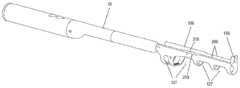
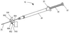
图1中显示了根据本发明的这种穿刺装置引导件的示例。图1是图示与腔内超声探头10一起使用的针引导装置100的一个实施例的等距视图,与本文描述的实施例一致。如图所示,针引导装置100包括具有尖端引导件135的探针适配器105、主体构件110、滑动构件115、支架构件120、注射器药筒构件125和引导板130。主体构件110、滑动构件115、支架构件120和注射器药筒构件125可统称为注射器支架组件140。优选地,所述尖端引导件135设计成当尖端引导件135接触患者时它防止探头10移动到患者体内更深处。为了防止这种情况,尖端引导件135优选地具有矩形或圆形形状。优选地,尖端引导件135具有孔或多个孔或间隙或槽以允许1根针或2、3、4、5、6、7、8、9、10、11、12、13、14、15、16、17、18、19或20根针穿过。更优选地,尖端引导件的孔、槽或间隙足够大以让一根或多根针穿过而不接触尖端引导件。这对于避免尖端引导件的潜在污染很重要。优选地,这种槽、间隙或孔的宽度为约0至约10mm,更优选约2至约8mm,更优选约3至约5mm。优选地,尖端引导件的尺寸在约0.5cm至约5cm×约0.5cm至约5cm的范围内,更优选为约1cm×约1.5cm或可选地约0.25cm2至约25cm2的面积。发明人发现尖端引导件135不仅适合于将针尖对准超声探头10的轴线,而且还允许阻止该装置在使用该装置期间意外进入内腔,例如直肠。如果装置意外进入内腔,则可能导致装置污染和/或对患者造成伤害。因此,尖端引导件135在用于患者时对于本发明的装置特别有用。An example of such a piercing device guide according to the invention is shown in FIG. 1 . Figure 1 is an isometric view illustrating one embodiment of a
在组装配置中并且在施用之前,具有针25的皮下注射器15可以如下所述被容纳在针引导装置100内。在使用期间,注射器15插入注射器药筒构件125中,然后其插入支架构件120中。移动滑动构件115以调节主体110和注射器15相对于探针10的位置,使得引导板130(以及其中的针25的远端)与探头适配器105的尖端引导件135接合。探头10可以插入患者的直肠,例如,不超过尖端引导件135。随着探头10定位在患者体内,滑动构件115进一步向前移动并且针25注射到患者体内。如果穿刺装置引导件包括如下文进一步描述的引导板130,随着探头10定位在患者体内,则滑动构件115进一步向前移动,使得主体110接触引导板130并且将针25注射到患者体内。发明人发现注射器针将被注射到患者体内约2至约10cm,更优选约3cm至约6cm,更优选约5cm,以便在注射器支架组件140连接到超声探头10时到达直肠括约肌。因此,注射器针25的远端和尖端引导件135、1135之间的距离优选为约2cm至约10cm,更优选为约3cm至约6cm,更优选为约5cm。在本发明的一个优选实施例中,穿刺装置引导件还包括引导板(130、1130),所述引导板包括:用于接收针(25)的孔(606)、凸台(608、1108)以及连接元件(602),凸台构造成由尖端引导件(135、1135)容纳,连接元件构造成将引导板(130、1130)可移除地附接到尖端引导件(135、1135)。在进一步优选的实施例中,引导板(130、1130)还包括多个不同径向距离处的孔(606),其中多个孔(606)中的每一个对应于针(25)路径的径向距离之一。In the assembled configuration and prior to administration, the
在本发明的优选实施例中,穿刺装置引导件构造成使得在组装构造中并且在给药之前,具有针25的皮下注射器15可以被容纳在针引导装置100内,如下所述。优选地进一步配置为在使用期间,注射器15可以插入注射器药筒构件125中,然后其可以插入支架构件120中。滑动构件115优选地构造成移动以调节主体110和注射器15相对于探头10的位置,使得探头适配器的尖端引导件135、1135与引导板130以及其中针25的远端接合。探头10优选地配置成插入患者的直肠,例如,不超过尖端引导件135、1135。在探头10定位在患者体内的情况下,滑动构件115优选地配置成进一步向前移动,使得主体110接触引导板130并且针25可以被注射到患者体内。优选地,穿刺装置引导件配置为针可以移动穿过引导板的孔、槽或间隙。发明人发现,使用如本文所描述的和如图7所示的引导板是特别有利的,因为针因此更好地稳定,即针尖需要更大的力以导致针相对于换能器的轴线的弯曲或移动(示例1,表1)。此外,发明人可以证明,这种引导板提高了针在肌肉组织中移动时的准确性,以便允许针尖更准确地到达目标位置(示例2,表2)。因此,为了解决本发明的目的,优选地并且特别有利地使用引导板130。进一步优选的是使用包括一个或多个孔606的引导板以容纳穿过其中的针25。优选地,包括多个孔606的引导板包括约2至约15个孔,更优选约2至约10个孔,甚至更优选约2至约5个孔。更进一步优选的是,包括一个或多个孔606的引导板包含凸台608、1108,其配置成被适配器105的尖端引导件135容纳。更优选地,这种引导板130包含连接元件602,其配置为可移除地将引导板130附接到尖端引导件135。更优选地,多个孔606各自对应于针25路径的选定径向距离。甚至更优选地,所述径向距离被选择为它们距探头10约0.1cm至约10cm,甚至更优选地距探头约0.1cm至约5cm,甚至更优选地距探头约0.1cm至约2cm。In a preferred embodiment of the invention, the piercing device guide is configured such that a
更优选地,所述引导板130、1130包括与连接元件(602)相邻的释放孔604,其中释放孔(604)构造成在其中接收将连接元件(602)从尖端引导件(135,1135)释放的突出部(360)。释放孔604优选地能够容纳优选地位于注射器支架组件140上的突出部360。所述释放孔构造成使得当它接收突出部360时,连接元件602从尖端引导件135释放。优选地,通过使突出部360进入释放孔604来释放引导板140导致引导板130附接至注射器支架组件140。优选地,穿刺装置引导件和引导板构造成使得引导板可以容易地更换,特别是在使用期间更换。优选地,穿刺装置引导件和引导板配置为每次注射使用新的引导板,即引导板在每次注射后是可更换的。More preferably, said
在进一步优选的实施例中,注射器支架组件(140)还包括突出部(360),其中,如果注射器支架组件(140)在适配器(105)上向前滑动,则突出部插入到释放孔(604)中以释放连接元件(602)并将引导板(130、1130)附接到注射器支架组件(140)。或者在本发明的优选实施例中,尖端引导件1135还包括一个或多个孔或槽(1107),更优选约2至约15个,更优选约2至约10个,甚至更优选约3至约5个在不同径向距离处的槽1107。优选地,径向距离为约0.5cm至约5cm,更优选为约0.5cm至约2cm并且甚至更优选为约0.5cm至约1cm。优选地,多个孔之间的距离为约0.1mm至约1mm。不同径向距离处的多个槽(1107)优选地配置为接收引导板(1130)的凸台(1108)。尖端引导件1135优选地配置为接收引导板1130的凸台1108。更优选地,多个槽1107中的每一个对应于针路径的径向距离之一。甚至更优选地,所述径向距离被选择为它们距探头10约0.1cm至约10cm,甚至更优选地距探头约0.1cm至约5cm,甚至更优选地距探头约0.1cm至约2cm。这种优选实施例的示例在图11A-11D中示出。In a further preferred embodiment, the syringe holder assembly (140) further comprises a protrusion (360), wherein if the syringe holder assembly (140) slides forward on the adapter (105), the protrusion is inserted into the release hole (604 ) to release the connection element (602) and attach the guide plate (130, 1130) to the syringe holder assembly (140). Or in a preferred embodiment of the invention,
在本发明的另一个优选实施例中,注射器支架组件(140)配置为在适配器(105)上向后滑动以将针(25)从患者身上缩回并返回经过尖端引导件(135、1135),其中,当注射器组件(140)向后滑动时,引导板(130、1130)保持附接至突出部。In another preferred embodiment of the present invention, the syringe holder assembly (140) is configured to slide back on the adapter (105) to retract the needle (25) from the patient and back past the tip guides (135, 1135) , wherein the guide plate (130, 1130) remains attached to the protrusion as the syringe assembly (140) slides backward.
主体110与引导板130的接合导致引导板130从尖端引导件135释放并附接至主体110。特别地,引导板130、1130可以配置为在它附接到主体110并从尖端引导件135、1135释放之后,它能够与注射器支架组件(140)一起在适配器上滑动,例如,如图9A和9B所示。Engagement of the
在本发明的一个实施例中,通过药筒构件125,注射器筒20在支架构件120内缩回以在从患者体内撤出期间施用其内容物。优选地,拉动滑动构件115导致针25相对于探头10和适配器105轴向移动最多约5cm,更优选地最多约3cm。优选地,拉动滑动构件115导致针25相对于尖端引导件135、1135轴向移动,从而将针25的远端到尖端引导件135、1135的距离减小约1cm至约10cm,更优选约2至约6cm并且甚至更优选约3cm。发明人发现这是特别有利的,因为通过这样的距离,整个长度的肌肉(优选肛门外括约肌)可以用悬浮液给药。In one embodiment of the invention,
当滑动构件115被完全拉向支架构件120的近端时(如图8B中的构造),针25的远端与尖端引导件135、1135之间的距离优选为约0.1cm至约3cm,更优选约1cm至约2cm,甚至更优选约1.5cm。发明人发现,针远端和尖端引导件之间保持这种距离特别有利,因为在将悬浮液给施加到患者体内后,当尖端引导件接触患者时针停留在患者体内,从而允许等待合理的时间使施用的悬浮液被患者的组织完全吸收。当从患者身上拔下针时,这可以防止悬浮液通过患者体外的注射通道发生任何回流。When the
在本发明的另一个优选实施例中,注射器支架组件140构造成在适配器105上向后滑动以将针25从患者身上缩回并返回经过尖端引导件。优选地,引导板130现在连接到主体110,向后拉动滑动构件115(例如,远离尖端引导件135),这将针25拉出尖端引导件135。In another preferred embodiment of the present invention, the
然后可以从支架构件120释放注射器药筒构件125,并且从注射器药筒构件125同时移除用过的注射器15和引导板130。The
在本发明的另一个实施例中,注射器支架组件140配置成向后滑动。In another embodiment of the present invention, the
图2A和2B分别是图1的探头10和探头适配器105的装配和等距视图。与本文所述的实施例一致,探头适配器105可包括尺寸和形状适合于超声探头10的外表面的大体管状结构。探头适配器105可以在探头10的远端上滑动并且通过摩擦/过盈配合保持在适当位置。探头适配器105可以配置为接收和支撑注射器支架组件140。如图所示,适配器105的上部包括附接导轨200,附接导轨200接合从主体构件110的下表面突出的相应夹子元件315,如图3A中所示并在下面详细描述。在一种实施方式中,附接导轨200包括相对取向的肋或突起210,它们一起形成平坦的上表面215,用于在其上支撑主体构件110。2A and 2B are assembled and isometric views, respectively, of
如图2A和2B所示,在一个实施例中,适配器105包括切口217,用于减轻适配器105的重量并允许访问位于超声探头10上不同位置的控件或端口。与本文所述的实施例一致,适配器105可以由塑料或聚合材料形成并且可以以任何合适的方式制造,例如注射成型、挤压成型、3D打印等。As shown in FIGS. 2A and 2B , in one embodiment, the
适配器105包括位于远端的尖端引导件135。尖端引导件135可以在基本上垂直于探头10/探头适配器105的纵轴线的平面中突出。如本文进一步描述的,引导板130可以可拆卸地夹在尖端引导件135上。尖端引导件135可以包括槽207,针25可以在选定的平行路径(例如,针25距探头10的选定径向距离)穿过槽207(例如,在注射程序期间)。
尽管附图中描绘的适配器105图示了特定配置,但是应当理解,可以基于与针引导装置100一起使用的超声探头的配置来实施不同的配置。此外,虽然未在图中描绘,但在使用中,可在附接超声探头10之前将无菌护套或其他覆盖物放置在超声探头10上或上方。Although the
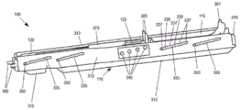
图3是说明注射器支架组件140的立体图。如图3所示,主体构件110包括具有纵向侧部312的大体框架状结构,纵向侧部312接收并支撑滑动构件115、支架构件120和注射器药筒构件125。注射器支架组件140结合后续附图进一步描述。FIG. 3 is a perspective view illustrating the
图4A和4B分别是示出了注射器支架组件140与探头适配器105的连接的侧视图和后视图。如图3、4A和4B所示,主体构件110还可包括在两个纵向侧部312的底部部分上的多个夹子元件315。夹子元件315间隔开以接合适配器105上的附接导轨200。特别地,每个夹子元件315可以包括倒钩构件或凹口,倒钩构件或凹口配置为接合附接导轨的下侧的一部分以将注射器支架组件140固定到适配器105,同时允许注射器支架组件140相对于超声探头10的纵向定位。4A and 4B are side and rear views, respectively, showing the connection of the
在一种实施方式中,在如图4A和4B所示的组装过程中,向下的力施加在主体构件110上,这导致夹子元件315接合附接导轨200的边缘部分。持续的向下力导致夹子元件315向外张开,允许夹子元件315的倒钩构件或凹口滑过并完全接合附接导轨200。在其他实施方式中,夹子元件315可以不包括倒钩构件,而是可以包括不成角度的向内的突出。在这样的实施例中,主体构件110可在组装期间纵向滑动到附接导轨200上。In one embodiment, during assembly as shown in FIGS. 4A and 4B , a downward force is exerted on the
如图3、4A和4B所示,纵向侧部312可包括多个路径调整通道335和路径选择孔340。在图示的实施例中,主体构件110包括四对相对的路径调节通道335和四对相对的路径选择孔340。在其他实施方式中,可以使用更多或更少的路径调整通道335和/或路径选择孔340。此外,虽然针对对应的纵向侧部312描述了成对的通道335和孔340,但是在一些实施方式中,通道335和/或孔340可以仅设置在主体构件110的一侧或交替侧上。As shown in FIGS. 3 , 4A and 4B , the
与本文所述的实施例一致,每个路径调整通道335形成大致成角度的通道,其具有对应于多个可能的路径位置的多个平坦部分337和成角度的部分339。在图示的实施例中,每个路径调节通道335包括四个平坦部分337和三个设置在每个平坦部分337之间的倾斜部分339。尽管不限于此,在一个实施方式中,第一(例如,最低)平坦部分337的底部和第四(例如,最高)平坦部分337的底部之间的竖直距离在约0至约10厘米(cm)的范围内,更优选约0.5至约5cm,甚至更优选约0.5至约1.5cm。在同一示例性实施例中,第一平坦部分337的中心与第四平坦部分337的中心之间的纵向距离在约0至约15cm的范围内,更优选约2至约15cm,甚至更优选约5到12cm左右。每个路径调节通道335配置为接收滑动构件115的相应选择销350,从而将滑动构件115的移动限制到由路径调节通道335限定的那些位置。Consistent with the embodiments described herein, each
路径选择孔340间隔开并定位成对应于路径调节通道335中的平坦部分337。如下所述,路径选择孔340之一配置为接收滑动构件115的相应部分,以将滑动构件115可靠地保持在由平坦部分337之一限定的位置,并防止在使用过程中沿着路径调节通道335的无意移动。
如图3所示,支架构件120的一部分延伸穿过主体构件110前部的开口(例如,在纵向侧部312之间)。更具体地,支架构件120的突出部360延伸超过主体构件110的前端并且配置成以下述方式接合引导板130。通过使滑动构件115相对于本体构件110滑动,选择销350可以定位在路径调节通道335的不同平坦部分337处。例如,可以推动或拉动滑动构件115的手柄370以改变选择销350的位置,这相应地改变由支架构件120和突出部360提供的平行路径(例如,附接导轨200上方的距离)。As shown in FIG. 3 , a portion of
图5A和5B是分别相对于探头适配器105处于升高(例如,最高)和降低(例如,最低)平行路径配置的注射器支架组件140的立体图。注射器支架组件140可以将带有针25的注射器15定位在距离超声探头的多个距离中的任意一个处以提供平行于探头10的纵轴线的注射路径。如上所述,从业者可为特定应用/患者选择平行路径。5A and 5B are perspective views of
图6A和6B是示出了与针引导板130接合的注射器15的侧视和后视等距图。注射器15可包括注射器筒20、筒凸缘22、针25、柱塞30和柱塞凸缘32。针引导板130可包括附接夹602或其他连接元件,每个都与释放孔604相邻。引导板130还可包括一组针尖高度选择孔606、板对准凸台608和一组导轨对准槽610。6A and 6B are side and rear isometric views showing the
针尖高度选择孔606的数量可对应于不同平坦部分337的数量,可使用主体构件110上的路径调节通道335选择平坦部分337。每个针尖高度选择孔606配置为在特定的平行路径上引导针25。也就是说,每个针尖高度选择孔606之间的径向间距(例如,相对于探头10)可以对应于不同平坦部分337之间的径向距离,使得当针25通过对应于平坦部分337之一的针尖高度选择孔606插入时,针25确保处于相对于探头10的平行路径。根据实施方式,从业者可以在将注射器15插入注射器支架组件140之前将针25插入通过选定的针尖高度选择孔606。The number of tip height selection holes 606 may correspond to the number of
图7A和7B是等距视图,示出了注射器15和针引导板130与注射器支架组件140和探头适配器105的连接。如图7A所示,注射器15和引导板130可以同时插入注射器支架组件140中,针25延伸穿过引导板130。7A and 7B are isometric views showing the connection of the
如图7B所示,注射器15可插入注射器药筒构件125。当注射器15插入注射器药筒构件125时,针25的尖端定位成邻近尖端引导件135,针25上的引导板130在主体构件110和尖端引导件135之间。当注射器15在注射器药筒构件125中时,引导板130的轨道对准槽610可围绕探头适配器105的轨道200配合。As shown in FIG. 7B , the
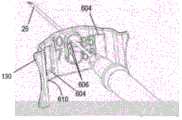
在注射器15和引导板130连接到注射器支架组件140之后,引导板130可以沿着针25纵向向前滑动(例如,由从业者),直到引导板130与尖端引导件135接合,如图1和7C所示。板对准凸台608可以配置成装配到尖端引导件135的槽207中。板对准凸台608可以以防止针25在插入和缩回期间接触尖端引导件135的方式穿过尖端引导件135的槽207。根据一个实施方式,连接夹子602可以配置成当板对准凸台608通过槽207插入时夹在适配器105上。更具体地,夹子602可以配置为当板对准凸台608插入尖端引导件135的槽207中时与尖端引导件135的相对边缘209对准。After the
图8A和8B是示出注射期间针引导装置100和注射器15的位置的立体图。随着探头110插入患者体内,优选地直到尖端引导件135接触患者的皮肤,注射器支架组件140可以沿附接导轨200从图1和图7C中所示的定位纵向向前推至图8A中所示的定位。注射器支架组件140的向前移动导致针25穿过引导板130,超过尖端引导件135,并进入患者体内,从而达到针进入患者体内高达约10cm的注射深度,更优选地高达约7cm甚至更优选约4至约5cm。当注射器支架组件140完全向前移动时,支架构件120的突出部360插入引导板130的释放孔604中。穿过孔604后,每个突出部360插入在边缘209和连接夹子602之间,推开(例如,向外)与每个释放孔604相邻的连接夹子602,并导致连接夹子602从尖端引导件135脱离。在使夹子602与尖端引导件135分离的同时,将突出部360插入释放孔604也使突出部360保持/夹紧引导板130。8A and 8B are perspective views showing the positions of the
当针25在患者体内时,从业者可以向(例如,挤压)突起365和注射器缩回支撑件367施加相反的力。如图8B所示,突起365可朝注射器缩回支撑件367纵向向后移动。当针25从患者体内抽出时,突起365上的力迫使针筒凸缘22朝柱塞凸缘32返回,导致针筒20缩回并通过针25释放其内容物。A practitioner may apply opposing forces to (eg, squeeze)
图9A和9B是示出针引导装置100和注射器15在注射之后的缩回位置的立体图。在完成注射后,从业者可在附接导轨200上纵向向后滑动注射器支架组件140(例如,同时探头10保留在患者体内)。引导板130,由于与突出部360接合,与注射器支架组件140一起缩回。9A and 9B are perspective views showing the retracted position of the
在注射器支架组件140和引导板130缩回之后,可将引导板130纵向向前推动以将引导板130与突出部360和注射器支架组件140分离,如图9B所示。例如,从业者可以轻轻地握住引导板130的侧面以弯曲引导板130并从释放孔604释放突出部360。根据一个实施方式,引导板130可以保持搁置在针25的远侧部分上。After the
图10A-C是在注射器15从针引导装置100弹出期间注射器药筒构件125的弹出器主体机构的立体图。注射器药筒构件125的释放构件373可以被提起(例如,由从业者),导致注射器药筒构件125将注射器15旋转出支架构件120,如图10A和10B所示。当注射器药筒构件125处于升高位置时,从业者可以畅通无阻地接触到注射器15的柱塞凸缘32和/或筒体20,在引导板130仍连接到针25的情况下,可以抓住注射器15并将其从注射器支架组件140中取出,如图10C所示。因此,注射器15和引导板130可以被移除和丢弃而无需从业者接触注射器15或引导板130的污染部分。10A-C are perspective views of the ejector body mechanism of the
图11A-11D是示出探头适配器和针引导板的另一个实施例的等距视图。图11A和11B显示了安装在注射器15的针25上的引导板1130的侧视和后视透视图,类似于上面结合图7A和7B描述的布置。类似于上面的描述,注射器15和引导板1130的组合可以同时插入注射器支架组件140中,其中针25延伸穿过引导板1130并且针25的远端邻近探头适配器1105的尖端引导件1135。11A-11D are isometric views showing another embodiment of a probe adapter and needle guide plate. Figures 1 IA and 1 IB show side and rear perspective views of a
与上述引导板130相反,引导板1130可仅包括一个孔1106,该孔配置为容纳针25。尖端引导件1135包括两个或更多个处于不同高度的槽1107,槽1107配置为接收板对准凸台1108。每个槽1107可以对应于上面结合(例如图3)描述的可选并行路径之一。因此,虽然在图11A-11D中仅示出了两个槽1107,但在其他实施方式中,尖端引导件1135可以包括多于两个的槽1107。In contrast to the
图11C和11D显示了附接到尖端引导件1135的引导板1130的侧视和后视透视图,类似于上面结合图1和7C描述的布置。在注射器15和引导板1130连接到注射器支架组件140之后,引导板1130可以沿着针25纵向向前滑动(例如,由从业者),直到引导板1130与尖端引导件1135接合,如图11C和11D所示。板对准凸台1108可以配置成装配到尖端引导件1135的选定槽1107中。根据一种实施方式,为注射器支架组件140选择特定的平行路径可以使针25和引导板1130与尖端引导件1135的对应槽1107对准。Figures 11C and 11D show side and rear perspective views of a
根据一种实施方式,本文所述的系统和方法可用于以放射状模式执行多次注射。在第一次注射后(例如,如上所述),当探头10留在患者体内时,如果需要,可以调整注射器支架组件140的径向插入距离(例如,如上文结合图5A和5B所述)。新的注射器15和引导板130的组合可以插入注射器支架组件140(如图7A-7C中所述),并且探头10可以旋转到患者优选的下一次注射定位,并可以使用上述过程执行第二次或后续注射。优选地,新的引导板130用于每次新的注射。According to one embodiment, the systems and methods described herein may be used to perform multiple injections in a radial pattern. After the first injection (e.g., as described above), while the
本发明还提供了一种进行注射的方法,该方法包括:The present invention also provides a method for injection, the method comprising:
(a)将探头适配器(140)附接到超声探头(10),其中探头适配器(105)包括位于远端的尖端引导件(135、1135);(a) attaching a probe adapter (140) to the ultrasound probe (10), wherein the probe adapter (105) includes a distally located tip guide (135, 1135);
(b)将注射器支架组件(140)附接到探头适配器(140),其中注射器支架组件可相对于探头适配器(140)纵向滑动;(b) attaching the syringe holder assembly (140) to the probe adapter (140), wherein the syringe holder assembly is longitudinally slidable relative to the probe adapter (140);
(c)将超声探头(10)插入患者体内;(c) inserting the ultrasound probe (10) into the body of the patient;
(d)调整注射器支架组件(140)以为注射器针(25)提供距超声探头(10)的选定径向距离;(d) adjusting the syringe holder assembly (140) to provide the syringe needle (25) with a selected radial distance from the ultrasound probe (10);
(e)将注射器(15)插入注射器支架组件(140),并将注射器针(25)与尖端引导件(135、1135)对齐;(e) Insert the syringe (15) into the syringe holder assembly (140) and align the syringe needle (25) with the tip guides (135, 1135);
(f)向远侧滑动注射器支架组件(140)以推动针通过尖端引导件(135、1135)并进入患者体内;(f) sliding the syringe holder assembly (140) distally to push the needle through the tip guides (135, 1135) and into the patient;
(g)向后滑动注射器支架组件(140)以使针(25)从患者身上缩回,以及(g) slide the syringe holder assembly (140) backward to retract the needle (25) from the patient, and
(h)从注射器支架组件(140)中移除注射器(15)。(h) Remove the syringe (15) from the syringe holder assembly (140).
优选地,将注射器(15)插入注射器支架组件(140)还包括(i)提供带有凸台(608、1108)和连接元件(602)的引导板(130、1130),该凸台构造成由尖端引导件(135、1135)接收,该连接元件(602)配置为可移除地将引导板(130、1130)附接到尖端引导件(135、1135);(ii)将注射器针(25)插入穿过引导板(130、1130)中的孔(606),以及(iii)在将注射器针(25)插入穿过孔(606)之后将注射器(15)插入注射器支架组件(140)。优选地,将注射器(15)插入注射器支架组件(140)还包括从尖端引导件(1135)中的多个孔(1107)中选择孔,其中多个孔(1107)中的每一个对应于不同的径向距离,该径向距离为注射器针(25)相对于超声探头(10)的径向距离。优选地,将注射器(15)插入注射器支架组件(140)还包括沿着注射器针(25)滑动引导板(130、1130),直到引导板(130、1130)连接到尖端引导件(135、1135)。优选地,引导板(130、1130)沿着注射器针(25)滑动,直到引导板(130、1130)附接到尖端引导件(135、1135)。这可以进一步包括移动引导板(130、1130)以使凸台(608、1108)与尖端引导件(135、1135)上的多个槽之一接合的步骤,其中多个槽中的每一个对应于不同的径向距离,该径向距离为注射器针(25)相对于超声探头(10)的径向距离。Preferably, inserting the syringe (15) into the syringe holder assembly (140) further comprises (i) providing a guide plate (130, 1130) with a boss (608, 1108) and a connecting element (602) configured to Received by the tip guide (135, 1135), the connection element (602) is configured to removably attach the guide plate (130, 1130) to the tip guide (135, 1135); (ii) attach the syringe needle ( 25) inserting through the hole (606) in the guide plate (130, 1130), and (iii) inserting the syringe (15) into the syringe holder assembly (140) after inserting the syringe needle (25) through the hole (606) . Preferably, inserting the syringe (15) into the syringe holder assembly (140) further comprises selecting a hole from a plurality of holes (1107) in the tip guide (1135), wherein each of the plurality of holes (1107) corresponds to a different The radial distance is the radial distance of the syringe needle (25) relative to the ultrasonic probe (10). Preferably, inserting the syringe (15) into the syringe holder assembly (140) further includes sliding the guide plate (130, 1130) along the syringe needle (25) until the guide plate (130, 1130) connects to the tip guide (135, 1135) ). Preferably, the guide plate (130, 1130) is slid along the syringe needle (25) until the guide plate (130, 1130) is attached to the tip guide (135, 1135). This may further include the step of moving guide plate (130, 1130) to engage boss (608, 1108) with one of a plurality of slots on tip guide (135, 1135), wherein each of the plurality of slots corresponds to In different radial distances, the radial distance is the radial distance of the syringe needle (25) relative to the ultrasonic probe (10).
优选地,当将注射器支架组件(140)向后滑动以将针(25)从患者体内缩回时,注射器针(25)不接触尖端引导件(135、1135),特别是为了避免尖端引导件(135、1135)的任何潜在污染。Preferably, when the syringe holder assembly (140) is slid back to retract the needle (25) from the patient, the syringe needle (25) does not contact the tip guides (135, 1135), in particular to avoid tip guides (135, 1135) for any potential contamination.
优选地,如果注射器支架组件(140)向远侧滑动以将针(25)推过尖端引导件(135、1135)并进入患者体内,则注射器支架组件(140)接合引导板(130、1130)并将引导板(130、1130)从尖端引导件(135、1135)上松开。更优选地,当将注射器支架组件(140)向后滑动以从患者体内缩回针(25)时,注射器支架组件(140)将引导板(130、1130)从尖端引导件(135、1135)缩回。Preferably, the syringe carriage assembly (140) engages the guide plate (130, 1130) if the syringe carriage assembly (140) is slid distally to push the needle (25) through the tip guide (135, 1135) and into the patient And release the guide plate (130, 1130) from the tip guide (135, 1135). More preferably, when the syringe carriage assembly (140) is slid backward to retract the needle (25) from the patient, the syringe carriage assembly (140) guides the guide plate (130, 1130) away from the tip guide (135, 1135) retract.
在根据本发明的方法的优选实施例中,该方法还包括通过沿着注射器针(25)的一部分向远侧滑动引导板(130、1130),将引导板(130、1130)从注射器支架组件(135、1135)分离的步骤。In a preferred embodiment of the method according to the present invention, the method further comprises removing the guide plate (130, 1130) from the syringe holder assembly by sliding the guide plate (130, 1130) distally along a portion of the syringe needle (25). (135, 1135) Separation step.
优选地,根据本发明的方法从注射器支架组件(140)移除注射器(15)的步骤进一步包括移除注射器(15)和引导板(130、1130),同时注射器针(25)仍然插入穿过引导板(130、1130)。Preferably, the step of removing the syringe (15) from the syringe holder assembly (140) according to the method of the present invention further comprises removing the syringe (15) and guide plate (130, 1130) while the syringe needle (25) is still inserted through Guide plates (130, 1130).
优选地,根据本发明的方法由根据本发明的任何穿刺装置执行。此外,根据本发明的穿刺装置优选地构造成用于根据本发明的方法。Preferably, the method according to the invention is performed by any piercing device according to the invention. Furthermore, the piercing device according to the invention is preferably configured for the method according to the invention.
图12是根据本文描述的实施方式使用平行路径穿刺装置引导件执行注射的示例性方法的流程图。如图12所示,过程1200可包括将探头适配器附接到超声探头(方框1205)以及将注射器支架组件附接到探头适配器(方框1210)。例如,如上文结合图2A-4B所述,探针适配器105可固定到探头10并且注射器支架组件140可夹到探头组件105的轨道200。12 is a flowchart of an exemplary method of performing an injection using a parallel path piercing device guide according to embodiments described herein. As shown in FIG. 12,
过程1200还可以包括将探头插入患者(方框1215),以及将注射器支架组件调整到用于注射器针的选定径向距离(方框1220)。例如,如上文结合图5A和5B所述,可以推动或拉动滑动构件115的手柄370以改变选择销350的位置,这相应地改变了支架构件120为注射器15限定的平行路径(例如,附件导轨200上方的径向距离)。
过程1200还可以包括将注射器插入注射器支架组件中并且将注射器的针与尖端引导件对齐(框1225)。例如,根据一个实施例,框1225可以包括下面描述的图13的步骤。在本发明的一个优选实施例中,待插入注射器支架中的注射器包含组合物和/或物质。更优选地,注射器包含药物活性组合物,例如细胞悬浮液。在优选实施例中,将插入有注射器(15),其填充有物质或组合物,的注射器药筒(125)向后滑动导致同时将物质或组合物施用于患者体内。优选地,这样的物质或组合物旨在通过过程1200的实施施用于患者。在另一个示例中,如结合图11A-11D所描述的,从业者可以将针25插入穿过引导板1130的选定孔1106,将注射器15插入注射器支架组件140中,然后将引导板1130附接至尖端引导件1135的选定槽1107。在又一实施方式中,尖端引导件1135可包括多个孔,多个孔对应于注射器支架组件调节的平行路径,并且针25可通过尖端引导件1135的选定孔插入。
过程1200还可以包括向远侧滑动注射器支架组件以将针推动通过尖端引导件并进入患者(方框1230),以及向回滑动注射器支架组件从患者内收回针(方框1235)。例如,如上文结合图8A-9B所述,随着探头110插入患者体内,注射器支架组件140可沿附接导轨200纵向向前推动。注射器支架组件140的向前运动导致针25穿过引导板130,超过尖端引导件135,并且进入患者体内。针25在患者体内时,从业者可以挤压突起365和注射器缩回支撑件367,导致注射器15通过针25释放或施用其内容物。优选地,突起365由此朝向缩回支撑件367移动限定的长度以引起针25相对于换能器的移动。这个长度优选为约2cm至约10cm,更优选约2cm至约5cm,甚至更优选约3cm。完成注射后,从业者可在附接导轨200上纵向向后滑动注射器支架组件140,同时探头10保持在患者体内。
过程1200可以进一步包括从注射器支架组件移除注射器并且处置注射器(框1240)。例如,注射器药筒构件125可旋转以将注射器15提升出支架构件120,如图10A和10B所示。在注射器药筒构件125处于升高位置的情况下,从业者可以抓住注射器15的柱塞凸缘32和/或筒20以从注射器支架组件140移除注射器15,同时引导板130仍然连接到针25,如图10C所示。因此,注射器15和引导板130可以被移除和处理而不需要从业者接触注射器15或引导板130的污染部分。
过程1200还可以包括确定是否需要额外的注射(框1245)。如果不需要对患者进行额外的注射(框1245–否),则过程1200可以包括从患者处移除超声探头(框1250)。如果需要为患者进行额外的注射(框1245–是),则过程1200可以返回到过程框1220,以在必要时使用新的注射器和引导板进行另一次注射。
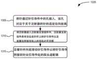
参见图13,过程框1225可以包括将针插入通过针引导件中的孔,该孔对应于注射器针的选定径向距离(框1305),将注射器插入注射器支架组件中,注射器支架组件具有定位在针杆上的针引导件以及放置在探头适配器的附接导轨上的导轨对齐凹槽(框1310),并且沿着针杆向前滑动针引导件以将针引导件附接到尖端引导件处的探头适配器(框1315)。例如,在将注射器15插入注射器支架组件140之前,从业者可将针25通过引导板130的选定孔606插入,使得选定孔606对应于注射器支架组件140被调整到的平行路径。如结合图6A-7C所描述的,从业者可以将注射器15插入注射器支架组件140中,引导板130搁置在附接导轨200上,并且向前滑动引导板130以附接到探头支架105的尖端引导件135。13,
本文描述的实施方式提供了一种引导装置,用于促进将穿刺装置(例如,针)放置在相对于超声探头的限定位置处。优选地,可以通过穿刺装置(例如针)将物质和/或组合物施用于患者体内。引导装置在针注射部位附近提供针尖的额外支撑件,以在整个注射过程中保持选定的路径。额外的支撑件会自动缩回,以便在注射后对用过的注射器进行简单处理。该引导装置最大限度地减少了与污染部件的接触,并能够在不从患者身上移除超声探头的情况下,为多次不同的注射实现注射器的插入、对齐和移除。Embodiments described herein provide a guide for facilitating placement of a puncturing device (eg, a needle) at a defined location relative to an ultrasound probe. Preferably, the substance and/or composition may be administered to the patient via a piercing device, such as a needle. The guide provides additional support for the needle tip near the needle injection site to maintain the selected path throughout the injection. The extra support retracts automatically for easy disposal of the used syringe after injection. The guide minimizes contact with contaminated parts and enables syringe insertion, alignment, and removal for multiple different injections without removing the ultrasound probe from the patient.
上述实施方式的描述提供了说明和描述,但并非旨在穷举或将本发明限制为所公开的精确形式。根据以上教导,修改和变化是可能的,或者可以从本发明的实践中获得。例如,虽然已经关于图12描述了一系列框,但是在其他实施例中可以修改框的顺序。此外,可以并行执行非从属框。The foregoing description of the embodiments has provided illustration and description, but is not intended to be exhaustive or to limit the invention to the precise forms disclosed. Modifications and variations are possible in light of the above teachings or may be acquired from practice of the invention. For example, while a series of blocks has been described with respect to Figure 12, the order of the blocks may be modified in other embodiments. Additionally, non-dependent blocks can be executed in parallel.
在本发明的一个实施例中,穿刺装置引导件适用于医疗用途。本文的医疗用途是指包括预防和/或治疗受试者,优选人、动物或哺乳动物的疾病的用途。优选地,医疗用途包括预防和/或治疗尿失禁、肛门失禁、膀胱过度活动症、膀胱活动不足、肛瘘、痔疮、(慢性)炎症、肌病、神经病和/或前列腺恶性肿瘤。更优选地,医疗用途是指用于预防和/或治疗肛门失禁,更优选地是急迫性大便失禁和/或被动大便失禁。为了允许装置的医疗用途,这种装置在使用时优选地是无菌的。因此,该装置优选设计成在使用前可灭菌。优选地,这种灭菌通过使用环氧乙烷、湿热、干热、辐射、汽化过氧化氢、氯气、汽化过乙酸和/或二氧化氮来进行。因此,该装置优选地由诸如钢、陶瓷和/或塑料的可消毒材料制成。甚至更优选地,该装置由包括塑料的可灭菌材料制成,更优选三元共聚物,甚至更优选丙烯腈-丁二烯-苯乙烯醇-共聚物。还优选的是,制造该装置的材料是生物相容的。如本文所用,生物相容性是指优选满足ISO 10993-1:2018的规范,更优选满足如ISO 10993-1:2018中定义的与完好皮肤和/或完好粘膜接触的规范。优选地,根据本发明的装置的材料,优选地满足所述生物相容性规格,选自钢、陶瓷和/或塑料,更优选地选自一类三元共聚物,甚至更优选地选自丙烯腈-丁二烯-苯乙烯-共聚物。还优选的是从任何丙烯腈丁二烯苯乙烯中选择装置材料,例如
本发明还提供一种如本文所述的穿刺装置引导件,用于通过手术或疗法治疗人体或动物体的方法。特别地,本发明提供了一种如本文所述的穿刺装置引导件,用于治疗和/或预防尿失禁、肛门失禁、膀胱过度活动症、膀胱活动不足、肛瘘、痔疮、(慢性)炎症、肌病、神经病和/或前列腺恶性肿瘤。优选地,在这样的方法中,药物活性物质和/或组合物被施用到损伤或疾病部位。优选地,在此类用于治疗和/或预防尿失禁和/或肛门失禁的方法中,药物活性物质和/或组合物被施用到肛门和/或尿道括约肌器官中。优选地,在此类用于治疗和/或预防膀胱过度活动和/或活动不足的方法中,将药物活性物质和/或组合物施用到膀胱中。优选地,在此类治疗和/或预防肛瘘的方法中,将药物活性物质和/或组合物施用到肛瘘中。优选地,在此类治疗和/或预防痔疮的方法中,将药物活性物质和/或组合物施用到痔疮中。优选地,在用于治疗和/或预防前列腺恶性肿瘤的此类方法中,将药物活性物质和/或组合物施用到恶性前列腺组织中。优选地,在用于治疗和/或预防慢性炎症、肌病或神经病的此类方法中,将药物活性物质和/或组合物分别施用到炎症部位、明显肌病部位或明显神经病部位。优选地,药物活性物质选自自体和/或同种异体细胞。在本发明的一个实施例中,穿刺装置引导件用于细胞的注射过程,如已经在EP2120976B1中公开的那样。施用到给定的组织或损伤部位的细胞包括在溶液或悬浮液中使治疗有效的数量的细胞,例如每100μl注射溶液约1×106至约6×106个细胞。注射溶液优选是生理上可接受的介质,有或没有自体血清。生理上可接受的介质可以是非限制性实例生理盐水或磷酸盐缓冲溶液。优选地,将细胞施用到肛门括约肌装置中作为肛门失禁的治疗以增强、改善和/或修复外部和/或内部肛门括约肌。优选地,将细胞注射到肛门外括约肌和/或肛门内括约肌内部或其周边,并存活并分化成成熟的肌肉细胞以增强括约肌和/或改善括约肌功能。根据该实施例的肌源性祖细胞的可行性和长期存活性之前已经显示(Messner等人,2021;Thurner等人,2020)。或者,优选的是,穿刺装置引导件用于通过将细胞注入从而增强和/或加强现有的失禁器官来预防肛门失禁。将细胞注入肌肉组织以治疗大便失禁的可行性已经得到证实(Frudinger等人,2018)。发明人发现,根据本发明的穿刺装置引导件对于预防和/或治疗肛门失禁特别有用,因为它对于将针注射到肛门括约肌器官和/或将细胞给药到肛门括约肌器官是特别准确和安全的。根据本发明的装置的增加的准确性以及安全性可能导致更有效地预防和/或治疗疾病。The present invention also provides a piercing device guide as described herein for use in a method of treating the human or animal body by surgery or therapy. In particular, the present invention provides a piercing device guide as described herein for use in the treatment and/or prevention of urinary incontinence, anal incontinence, overactive bladder, underactive bladder, anal fistula, hemorrhoids, (chronic) inflammation, Myopathy, neuropathy and/or prostate malignancy. Preferably, in such methods, the pharmaceutically active substance and/or composition is administered to the site of injury or disease. Preferably, in such methods for the treatment and/or prevention of urinary and/or anal incontinence, the pharmaceutically active substance and/or composition is administered into the anal and/or urinary sphincter organ. Preferably, in such methods for treating and/or preventing overactive and/or underactive bladder, the pharmaceutically active substance and/or composition is administered into the bladder. Preferably, in such methods of treating and/or preventing anal fistulas, the pharmaceutically active substance and/or composition is administered into the anal fistula. Preferably, in such methods of treating and/or preventing hemorrhoids, the pharmaceutically active substance and/or composition is administered to the hemorrhoids. Preferably, in such methods for treating and/or preventing prostate malignancies, the pharmaceutically active substance and/or composition is administered to malignant prostate tissue. Preferably, in such methods for the treatment and/or prevention of chronic inflammation, myopathy or neuropathy, the pharmaceutically active substance and/or composition is administered to the site of inflammation, overt myopathy or overt neuropathy, respectively. Preferably, the pharmaceutically active substance is selected from autologous and/or allogeneic cells. In one embodiment of the invention, the piercing device guide is used for the injection procedure of cells, as already disclosed in EP2120976B1. Cells administered to a given tissue or lesion include a therapeutically effective number of cells in solution or suspension, eg, about 1 x10⁶ to about 6 x10⁶ cells per 100 μl of injection solution. Solutions for injection are preferably in a physiologically acceptable medium, with or without autologous serum. A physiologically acceptable medium may be, for non-limiting examples, physiological saline or phosphate buffered saline. Preferably, the cells are administered into the anal sphincter device to strengthen, improve and/or repair the external and/or internal anal sphincter as a treatment for anal incontinence. Preferably, the cells are injected into or around the external anal sphincter and/or internal anal sphincter and survive and differentiate into mature muscle cells to strengthen the sphincter and/or improve sphincter function. The viability and long-term viability of myogenic progenitor cells according to this example has been shown previously (Messner et al., 2021; Thurner et al., 2020). Alternatively, preferably, the piercing device guide is used to prevent anal incontinence by injecting cells to augment and/or strengthen existing incontinence organs. The feasibility of injecting cells into muscle tissue to treat fecal incontinence has been demonstrated (Frudinger et al., 2018). The inventors have found that the piercing device guide according to the present invention is particularly useful for the prevention and/or treatment of anal incontinence as it is particularly accurate and safe for injecting needles and/or administering cells to the anal sphincter organ . The increased accuracy and safety of the device according to the invention may lead to more effective prevention and/or treatment of diseases.
本发明还提供了一种如本文所述的引导板(130、1130)。所述引导板优选地包括孔(606)以接收从中穿过的针(25),和凸台(608、1108),其构造成由根据本发明的穿刺装置引导件的尖端引导件(135、1135)接收。引导板(130、1130)优选还包括连接元件(602),其构造成将引导板(130、1130)可拆卸地附接到根据本发明的穿刺装置引导件的尖端引导件(135、1135)。优选地,引导板(130、1130)还包括:多个径向距离不同的孔(606),每个孔(606)对应根据本发明的穿刺装置引导件的针(25)路径的径向距离之一。引导板(130、1130)还可包括与连接元件(602)相邻的释放孔(604),其中释放孔(604)配置成在其中接收突出部(360),该突出部(360)使连接元件(602)从根据本发明的穿刺装置引导件的尖端引导件(135、1135)释放。The invention also provides a guide plate (130, 1130) as described herein. The guide plate preferably includes a hole (606) to receive the needle (25) therethrough, and a boss (608, 1108) configured to be guided by the tip (135, 135, 1108) of the piercing device guide according to the invention. 1135) Receive. The guide plate (130, 1130) preferably further comprises a connecting element (602) configured to detachably attach the guide plate (130, 1130) to the tip guide (135, 1135) of the piercing device guide according to the invention . Preferably, the guide plate (130, 1130) further comprises: a plurality of holes (606) with different radial distances, each hole (606) corresponding to the radial distance of the needle (25) path of the puncture device guide according to the present invention one. The guide plate (130, 1130) may also include a release hole (604) adjacent to the connection element (602), wherein the release hole (604) is configured to receive a protrusion (360) therein that enables the connection The element (602) is released from the tip guide (135, 1135) of the piercing device guide according to the invention.
尽管上面已经详细描述了本发明,但是应当明确理解,对于相关领域的技术人员来说显而易见的是,在不脱离本发明的精神的情况下可以对本发明进行修改。在不脱离本发明的范围的情况下,可以对本发明进行形式、设计或布置的各种改变。上面说明的不同组合可以组合在单个实施例中。因此,上述描述被认为是示例性的,而不是限制性的,并且本发明的真实范围由所附权利要求限定。While the invention has been described in detail above, it should be clearly understood that modifications can be made thereto without departing from the spirit of the invention, as would be apparent to those skilled in the relevant art. Various changes in form, design or arrangement may be made in the present invention without departing from the scope of the invention. The different combinations described above can be combined in a single embodiment. Accordingly, the foregoing description is to be considered as illustrative rather than restrictive, with the true scope of the invention being defined by the appended claims.
以下实施例解释了本发明但不认为是限制性的。The following examples illustrate the invention but are not to be considered as limiting.
示例1–通过针偏转进行力测量Example 1 – Force Measurement via Needle Deflection
根据图7的注射器支架组件在引导板(130)连接或不连接时进行了测试,以证明这种引导板的功能效果。Terumo Agani 21Gx2″(0.8*50mm)常规斜角11°针(参考号AN*2150R1)在组件中用作穿刺装置(25),并连接到1mL B-Braun
表1:当连接到不同的注射器支架组件时,针尖在不同偏转下的力测量结果Table 1: Force measurements of the needle tip at different deflections when attached to different syringe holder assemblies

示例2–肌肉组织中的引导精度测量Example 2 – Guided Accuracy Measurements in Muscle Tissue
为了解决通过肌肉组织引导穿刺装置的准确性,将不同的注射器支架组件(一个相当于EP2170440A2的装置以及根据图7的装置,装置包括或不包括引导板130)连接到BK8848超声换能器,该换能器被换能器凝胶填充乳胶盖覆盖。然后每个注射器支架组件配备BBraun 1ml注射器以及21口径长刺血针常规斜面针。BK8848超声换能器连接到BKFlexFocus超声系统,用于可视化换能器记录的信号。将注射器支架组件放入水浴中,将针沿BK8848力传感器的轴向前引导,直到针尖到达传感器的横向检测窗口。每个注射器支架组件在超声系统中可见的针尖都标有“x”,以便以后在组织中引导穿刺装置时测量准确性。猪肌肉组织的制备方法是使用手术刀在组织上切孔,让BK8848换能器进入孔内,从而类似于腔内检查。接下来,使用每个注射器支架组件将总共12根针引导到肌肉组织的各个部位,每个部位最大深度为5cm,这应该允许针到达换能器传感器的窗口。对于每根穿过肌肉组织的针,都标记了超声系统中可见的针尖位置,并以毫米为单位测量了与先前设置的“x”位置的距离,以了解针在穿过肌肉组织时偏转了多少。计算重复测量的平均值和标准偏差值,以比较每个注射器支架组件的准确性。如表2所示,与相当于EP2170440A2的装置导致1.98±0.35mm偏转以及图7不包括引导板130的注射器支架组件导致针偏转2.23±0.85mm相比,本发明的包括引导板130的注射器支架组件导致1.92±0.58mm的最低针偏转。In order to address the accuracy of guiding the puncture device through the muscle tissue, different syringe holder assemblies (one equivalent to EP2170440A2 and the device according to Figure 7, with or without the guide plate 130) were connected to the BK8848 ultrasonic transducer, which The transducer is covered by a transducer gel-filled latex cover. Each syringe holder assembly was then equipped with a BBraun 1 ml syringe and a 21 gauge long lancet regular bevel needle. The BK8848 ultrasound transducer is connected to the BKFlexFocus ultrasound system for visualization of the signal recorded by the transducer. Place the syringe holder assembly in the water bath and guide the needle forward along the axis of the BK8848 force sensor until the needle tip reaches the sensor's lateral detection window. The needle tip of each syringe holder assembly visible in the ultrasound system is marked with an "x" for later measurement of accuracy when guiding the puncture device through tissue. Porcine muscle tissue was prepared by using a scalpel to cut a hole in the tissue, allowing the BK8848 transducer to enter the hole, similar to an endoluminal examination. Next, use each syringe holder assembly to guide a total of 12 needles into various sites of muscle tissue, each to a maximum depth of 5 cm, which should allow the needles to reach the window of the transducer sensor. For each needle passing through the muscle tissue, the position of the needle tip visible on the ultrasound system was marked and the distance in millimeters from the previously set "x" position for deflection of the needle as it passed through the muscle tissue was marked How many. Calculate the mean and standard deviation values of repeated measurements to compare the accuracy of each syringe holder assembly. As shown in Table 2, compared to the device equivalent to EP2170440A2 which resulted in 1.98±0.35mm deflection and the syringe holder assembly of FIG. The assembly resulted in the lowest needle deflection of 1.92±0.58mm.
表2:猪肌肉组织中的针偏转测量结果Table 2: Needle deflection measurements in porcine muscle tissue

参考文献references
Frudinger,A.,Marksteiner,R.,Pfeifer,J.,Margreiter,E.,Paede,J.,Thurner,M.,2018.Skeletal muscle-derived cell implantation for the treatmentof sphincter-related faecal incontinence.Stem Cell Research&Therapy 9,233.Frudinger, A., Marksteiner, R., Pfeifer, J., Margreiter, E., Paede, J., Thurner, M., 2018. Skeletal muscle-derived cell implantation for the treatment of sphincter-related faecal incontinence. Stem Cell Research & Therapy 9,233.
Messner,F.,Thurner,M.,Müller,J.,Blumer,M.,Hofmann,J.,Marksteiner,R.,Couillard-Despres,S.,Troppmair,J.,
Thurner,M.,Deutsch,M.,Janke,K.,Messner,F.,Kreutzer,C.,Beyl,S.,Couillard-Després,S.,Hering,S.,Troppmair,J.,Marksteiner,R.,2020.Generation ofmyogenic progenitor cell-derived smooth muscle cells for sphincterregeneration.Stem Cell Res Ther 11,233.Thurner, M., Deutsch, M., Janke, K., Messner, F., Kreutzer, C., Beyl, S., Couillard-Després, S., Hering, S., Troppmair, J., Marksteiner, R .,2020.Generation of myogenic progenitor cell-derived smooth muscle cells for sphincter regeneration.Stem Cell Res Ther 11,233.
Claims (24)
Translated fromChineseApplications Claiming Priority (3)
| Application Number | Priority Date | Filing Date | Title |
|---|---|---|---|
| US202063039515P | 2020-06-16 | 2020-06-16 | |
| US63/039,515 | 2020-06-16 | ||
| PCT/EP2021/066086WO2021255016A1 (en) | 2020-06-16 | 2021-06-15 | Parallel path puncture device guide and method |
Publications (1)
| Publication Number | Publication Date |
|---|---|
| CN115768357Atrue CN115768357A (en) | 2023-03-07 |
Family
ID=76641645
Family Applications (1)
| Application Number | Title | Priority Date | Filing Date |
|---|---|---|---|
| CN202180043258.8APendingCN115768357A (en) | 2020-06-16 | 2021-06-15 | Parallel path piercing device guide and method |
Country Status (12)
| Country | Link |
|---|---|
| US (1) | US12295782B2 (en) |
| EP (1) | EP4164502A1 (en) |
| JP (1) | JP7725078B2 (en) |
| KR (1) | KR20230025881A (en) |
| CN (1) | CN115768357A (en) |
| AU (1) | AU2021294240A1 (en) |
| BR (1) | BR112022025781A2 (en) |
| CA (1) | CA3180026A1 (en) |
| CL (1) | CL2022003581A1 (en) |
| IL (1) | IL299056A (en) |
| MX (1) | MX2022016398A (en) |
| WO (1) | WO2021255016A1 (en) |
Families Citing this family (8)
| Publication number | Priority date | Publication date | Assignee | Title |
|---|---|---|---|---|
| WO2021067734A1 (en) | 2019-10-04 | 2021-04-08 | Civco Medical Instruments Co., Inc. | Parallel path puncture device guide |
| US11877810B2 (en) | 2020-07-21 | 2024-01-23 | Bard Access Systems, Inc. | System, method and apparatus for magnetic tracking of ultrasound probe and generation of 3D visualization thereof |
| EP4185209A1 (en) | 2020-08-04 | 2023-05-31 | Bard Access Systems, Inc. | System and method for optimized medical component insertion monitoring and imaging enhancement |
| WO2022035760A1 (en) | 2020-08-10 | 2022-02-17 | Bard Access Systems, Inc. | System and method for generating vessel representations in mixed reality/virtual reality |
| WO2022072727A2 (en) | 2020-10-02 | 2022-04-07 | Bard Access Systems, Inc. | Ultrasound systems and methods for sustained spatial attention |
| EP4228516A1 (en) | 2020-10-15 | 2023-08-23 | Bard Access Systems, Inc. | Ultrasound imaging system for generation of a three-dimensional ultrasound image |
| US12102481B2 (en)* | 2022-06-03 | 2024-10-01 | Bard Access Systems, Inc. | Ultrasound probe with smart accessory |
| US12137989B2 (en) | 2022-07-08 | 2024-11-12 | Bard Access Systems, Inc. | Systems and methods for intelligent ultrasound probe guidance |
Citations (6)
| Publication number | Priority date | Publication date | Assignee | Title |
|---|---|---|---|---|
| US20050059891A1 (en)* | 2003-07-17 | 2005-03-17 | Kabushiki Kaisha Toshiba | Paracentesis needle holder |
| CN1895182A (en)* | 2005-06-06 | 2007-01-17 | 舍伍德服务股份公司 | Needle assembly with removable depth stop |
| US20150250447A1 (en)* | 2012-11-23 | 2015-09-10 | Kabushiki Kaisha Toshiba | Puncture adapter and ultrasound probe |
| CN104918555A (en)* | 2012-07-10 | 2015-09-16 | 富士胶片索诺声公司(美国) | Ultrasonic probe and aligned needle guide system |
| US20150327885A1 (en)* | 2013-12-12 | 2015-11-19 | Catalin Esanu | Method and device for ultrasound guided minimal invasive access of a bodily cavity |
| US20170020558A1 (en)* | 2015-07-07 | 2017-01-26 | Zmk Medical Technologies Inc. | Transperineal needle guidance |
Family Cites Families (42)
| Publication number | Priority date | Publication date | Assignee | Title |
|---|---|---|---|---|
| US4900303A (en) | 1978-03-10 | 1990-02-13 | Lemelson Jerome H | Dispensing catheter and method |
| US4776346A (en) | 1984-02-10 | 1988-10-11 | Dan Beraha | Biopsy instrument |
| US4883059A (en) | 1986-11-21 | 1989-11-28 | Advanced Technology Laboratories, Inc. | Intravaginal transducer biopsy guide |
| ATE64487T1 (en) | 1986-12-05 | 1991-06-15 | Siemens Ag | INTRACAVITARY ULTRASOUND SCANNING DEVICE. |
| US4877033A (en) | 1988-05-04 | 1989-10-31 | Seitz Jr H Michael | Disposable needle guide and examination sheath for transvaginal ultrasound procedures |
| US4892520A (en) | 1988-07-13 | 1990-01-09 | Gilbaugh James H | Finger mounted surgical needle guide/needle protector |
| US4899756A (en) | 1988-07-18 | 1990-02-13 | Sonek Jiri D | Articulated needle guide for ultrasound imaging and method of using same |
| US5078144A (en) | 1988-08-19 | 1992-01-07 | Olympus Optical Co. Ltd. | System for applying ultrasonic waves and a treatment instrument to a body part |
| EP0446645A1 (en) | 1990-02-20 | 1991-09-18 | Acoustic Imaging Technologies Corporation | Method and apparatus for ultrasonically probing a prostate |
| US5235987A (en) | 1991-02-22 | 1993-08-17 | Dymax Corporation | Needle guide |
| US5494039A (en) | 1993-07-16 | 1996-02-27 | Cryomedical Sciences, Inc. | Biopsy needle insertion guide and method of use in prostate cryosurgery |
| US6309374B1 (en) | 1998-08-03 | 2001-10-30 | Insite Vision Incorporated | Injection apparatus and method of using same |
| JP2001340334A (en) | 2000-06-01 | 2001-12-11 | Ge Medical Systems Global Technology Co Llc | Piercing needle guiding utensil, ultrasonic probe and ultrasonic imaging device |
| EP1337183B1 (en) | 2000-11-24 | 2005-05-25 | Innovacell Biotechnologie GmbH | Ultrasonic probe comprising a positioning device for examination devices and operation devices |
| US6695786B2 (en) | 2001-03-16 | 2004-02-24 | U-Systems, Inc. | Guide and position monitor for invasive medical instrument |
| JP4109272B2 (en) | 2004-07-09 | 2008-07-02 | 直彦 徳本 | Puncture adapter |
| DE102005025639B4 (en) | 2005-06-03 | 2011-04-07 | Innovacell Biotechnologie Gmbh | injection device |
| FR2895681A1 (en) | 2005-12-30 | 2007-07-06 | Pascal Muller | Product anti-wrinkle intradermal injection device for use in e.g. cosmetic field, has control unit subjecting nozzle to backward movement in direction opposite to product flow, during establishment of flow under impulsion of pushing unit |
| US20080208164A1 (en) | 2007-02-28 | 2008-08-28 | Innovacell Biotechnologie Gmbh | Methods for the treatment of anal incontinence |
| JP2008212608A (en) | 2007-03-01 | 2008-09-18 | Akio Ichihara | Deep vein puncture assisting tool |
| DE102007063660A1 (en) | 2007-07-25 | 2009-04-30 | Innovacell Biotechnologie Gmbh | Injection device for injection into biological tissue and injection depot |
| US8926494B1 (en) | 2008-03-26 | 2015-01-06 | Uromedica, Inc. | Method and apparatus for placement of implantable device adjacent a body lumen |
| US8702654B2 (en) | 2009-03-25 | 2014-04-22 | John M. Agee | Treatment of carpal tunnel syndrome by injection of the flexor retinaculum |
| FR2949316A1 (en) | 2009-08-31 | 2011-03-04 | Koelis | CONTROL SYSTEM AND METHOD FOR PRECISE GUIDANCE TO THE PROSTATE OF A PERCUTANEOUS NEEDLE |
| US9055899B2 (en) | 2009-10-22 | 2015-06-16 | Facet Technologies, Llc | Lancing device with improved guidance assembly |
| US9033880B2 (en) | 2011-04-05 | 2015-05-19 | Houston Medical Robotics, Inc. | Robotic insertion systems and methods |
| US9724070B2 (en) | 2011-08-01 | 2017-08-08 | University Of Florida Research Foundation, Inc. | Apparatus for facilitating ultrasound-assisted needle placement for drug delivery |
| CN104619366B (en) | 2013-08-14 | 2017-05-31 | 泰尔茂株式会社 | syringe |
| US12144519B2 (en) | 2014-04-03 | 2024-11-19 | Corbin Clinical Resources, Llc | Transperineal prostate biopsy and treatment methods |
| US10743909B2 (en) | 2014-04-03 | 2020-08-18 | Corbin Clinical Resources, Llc | Transperineal prostate biopsy device, systems, and methods of use |
| US10507038B2 (en) | 2014-11-12 | 2019-12-17 | Civco Medical Instruments Co., Inc. | Needle guide devices for mounting on imaging transducers or adaptors on imaging transducer, imaging transducers for mounting needle guide devices and adaptors for imaging transducers for mounting needle guide devices thereon |
| CA3050807A1 (en) | 2016-01-20 | 2017-07-27 | Loughborough University | Needle guides |
| WO2017205468A1 (en)* | 2016-05-24 | 2017-11-30 | Civco Medical Instruments Co., Inc. | Low profile endocavity needle guides |
| JP2019534726A (en) | 2016-09-23 | 2019-12-05 | イグザクト ロボティックス リミテッド | Universal holder for insertable medical tools |
| CN109512473A (en) | 2017-09-20 | 2019-03-26 | 史军 | Medical Devices with visual puncturing device |
| CA3095956A1 (en)* | 2018-04-13 | 2019-10-17 | Isys Medizintechnik Gmbh | Medical robot |
| JP7258496B2 (en) | 2018-09-25 | 2023-04-17 | キヤノンメディカルシステムズ株式会社 | Injection guide device and injection guide program for radiotherapy drug |
| US20220096065A1 (en) | 2018-09-28 | 2022-03-31 | Praxis Holding Llc | Oscillating syringe system and needle |
| US10765411B2 (en) | 2018-09-28 | 2020-09-08 | John Steele Fisher | Oscillating syringe system |
| US12303162B2 (en)* | 2019-03-13 | 2025-05-20 | Exact Imaging Inc. | Needle guide for an angled endocavity transducer |
| CN109771811B (en) | 2019-03-23 | 2021-06-22 | 哈尔滨理工大学 | A Parallel Robot for Prostate Flexible Needle Particle Implantation |
| WO2021067734A1 (en) | 2019-10-04 | 2021-04-08 | Civco Medical Instruments Co., Inc. | Parallel path puncture device guide |
- 2021
- 2021-06-15CNCN202180043258.8Apatent/CN115768357A/enactivePending
- 2021-06-15JPJP2022574618Apatent/JP7725078B2/enactiveActive
- 2021-06-15BRBR112022025781Apatent/BR112022025781A2/ennot_activeApplication Discontinuation
- 2021-06-15MXMX2022016398Apatent/MX2022016398A/enunknown
- 2021-06-15EPEP21735188.1Apatent/EP4164502A1/enactivePending
- 2021-06-15WOPCT/EP2021/066086patent/WO2021255016A1/ennot_activeCeased
- 2021-06-15KRKR1020237001865Apatent/KR20230025881A/ennot_activeWithdrawn
- 2021-06-15CACA3180026Apatent/CA3180026A1/enactivePending
- 2021-06-15ILIL299056Apatent/IL299056A/enunknown
- 2021-06-15USUS18/001,926patent/US12295782B2/enactiveActive
- 2021-06-15AUAU2021294240Apatent/AU2021294240A1/enactivePending
- 2022
- 2022-12-15CLCL2022003581Apatent/CL2022003581A1/enunknown
Patent Citations (6)
| Publication number | Priority date | Publication date | Assignee | Title |
|---|---|---|---|---|
| US20050059891A1 (en)* | 2003-07-17 | 2005-03-17 | Kabushiki Kaisha Toshiba | Paracentesis needle holder |
| CN1895182A (en)* | 2005-06-06 | 2007-01-17 | 舍伍德服务股份公司 | Needle assembly with removable depth stop |
| CN104918555A (en)* | 2012-07-10 | 2015-09-16 | 富士胶片索诺声公司(美国) | Ultrasonic probe and aligned needle guide system |
| US20150250447A1 (en)* | 2012-11-23 | 2015-09-10 | Kabushiki Kaisha Toshiba | Puncture adapter and ultrasound probe |
| US20150327885A1 (en)* | 2013-12-12 | 2015-11-19 | Catalin Esanu | Method and device for ultrasound guided minimal invasive access of a bodily cavity |
| US20170020558A1 (en)* | 2015-07-07 | 2017-01-26 | Zmk Medical Technologies Inc. | Transperineal needle guidance |
Also Published As
| Publication number | Publication date |
|---|---|
| US12295782B2 (en) | 2025-05-13 |
| EP4164502A1 (en) | 2023-04-19 |
| JP7725078B2 (en) | 2025-08-19 |
| BR112022025781A2 (en) | 2023-01-10 |
| CL2022003581A1 (en) | 2023-06-16 |
| US20230240643A1 (en) | 2023-08-03 |
| MX2022016398A (en) | 2023-01-30 |
| WO2021255016A1 (en) | 2021-12-23 |
| IL299056A (en) | 2023-02-01 |
| KR20230025881A (en) | 2023-02-23 |
| JP2023529864A (en) | 2023-07-12 |
| AU2021294240A1 (en) | 2023-02-02 |
| CA3180026A1 (en) | 2021-12-23 |
Similar Documents
| Publication | Publication Date | Title |
|---|---|---|
| US12295782B2 (en) | Parallel path puncture device guide and method | |
| AU2002355386B2 (en) | Flexible tissue injection catheters with controlled depth penetration | |
| US20090187118A1 (en) | Multiple Needle System | |
| US6835193B2 (en) | Methods for controlled depth injections into interior body cavities | |
| US10426900B2 (en) | Automatic injection device | |
| AU2002355386A1 (en) | Flexible tissue injection catheters with controlled depth penetration | |
| AU2002320369A1 (en) | Methods for controlled depth injections into interior body cavities | |
| JP2011517582A (en) | Guidewire and delivery catheter with fiber optic detection components, and related systems and methods | |
| KR20170076705A (en) | Apparatuses, systems and methods for controlled delivery of therapeutics and related substances | |
| WO2022236057A1 (en) | Therapeutic infusion needle | |
| US11950804B2 (en) | Parallel path puncture device guide | |
| WO2007140381A2 (en) | Multiple needle system | |
| JPWO2021255016A5 (en) | ||
| US20160206296A1 (en) | Biopsy Syringe Device | |
| HK1057496A1 (en) | An arrangement and method for interacting with an internal body organ | |
| HK1057496B (en) | An arrangement and method for interacting with an internal body organ |
Legal Events
| Date | Code | Title | Description |
|---|---|---|---|
| PB01 | Publication | ||
| PB01 | Publication | ||
| SE01 | Entry into force of request for substantive examination | ||
| SE01 | Entry into force of request for substantive examination |