Movatterモバイル変換


[0]ホーム

URL:


CN115767331A - Electronic equipment - Google Patents

Electronic equipment
Download PDF

Info

Publication number
CN115767331A
CN115767331ACN202211419624.8ACN202211419624ACN115767331ACN 115767331 ACN115767331 ACN 115767331ACN 202211419624 ACN202211419624 ACN 202211419624ACN 115767331 ACN115767331 ACN 115767331A
Authority
CN
China
Prior art keywords
electronic device
piezoelectric film
speaker
display screen
diaphragm
Prior art date
Legal status (The legal status is an assumption and is not a legal conclusion. Google has not performed a legal analysis and makes no representation as to the accuracy of the status listed.)
Pending
Application number
CN202211419624.8A
Other languages
Chinese (zh)
Inventor
王三军
严笔祥
Current Assignee (The listed assignees may be inaccurate. Google has not performed a legal analysis and makes no representation or warranty as to the accuracy of the list.)
Realme Mobile Telecommunications Shenzhen Co Ltd
Original Assignee
Realme Mobile Telecommunications Shenzhen Co Ltd
Priority date (The priority date is an assumption and is not a legal conclusion. Google has not performed a legal analysis and makes no representation as to the accuracy of the date listed.)
Filing date
Publication date
Application filed by Realme Mobile Telecommunications Shenzhen Co LtdfiledCriticalRealme Mobile Telecommunications Shenzhen Co Ltd
Priority to CN202211419624.8ApriorityCriticalpatent/CN115767331A/en
Publication of CN115767331ApublicationCriticalpatent/CN115767331A/en
Pendinglegal-statusCriticalCurrent

Links

Images

Landscapes

Abstract

The embodiment of the application provides an electronic equipment, including center, display screen, speaker and piezoelectric film, the center includes medium plate and frame, and the frame encloses the edge of locating the medium plate, and the medium plate still is provided with the intercommunicating pore including first surface and the second surface that carry on the back mutually, and the intercommunicating pore runs through first surface and second surface. The display screen is installed in the frame to relative with the first surface of medium plate, form the clearance between display screen and the first surface, intercommunicating pore intercommunication clearance. The loudspeaker comprises a shell and a vibrating diaphragm, wherein the shell is arranged on the second surface of the middle plate and seals the communication hole, and the vibrating diaphragm is arranged on the shell and corresponds to the communication hole so that the gap serves as a front cavity of the loudspeaker. Piezoceramics pastes the surface of locating the display screen towards the medium plate. The electronic equipment that this application embodiment provided can guarantee good tone quality, has also reduced the trompil simultaneously.

Description

Translated fromChinese
电子设备Electronic equipment

技术领域technical field

本申请涉及移动终端技术领域,具体涉及一种电子设备。The present application relates to the technical field of mobile terminals, and in particular to an electronic device.

背景技术Background technique

相关技术中,对于手机等电子设备而言,通常都会设置扬声器、受话器等音频播放设备,音频播放设备通常设置在电子设备的壳体内,为了将音频播放设备播放的音频引导至用户,需要在壳体上开孔。而通常电子设备还设置有显示屏,为了使得受话器出声,通常还需要再壳体的设置显示屏的一侧设置出音孔,限制显示屏的尺寸,同时也带来防水防尘的问题。In related technologies, for electronic devices such as mobile phones, audio playback devices such as speakers and receivers are usually provided. The audio playback device is usually installed in the casing of the electronic device. Holes in the body. Usually, the electronic device is also provided with a display screen. In order to make the receiver sound, it is usually necessary to set a sound outlet on one side of the display screen of the housing, which limits the size of the display screen and also brings waterproof and dustproof problems.

相关技术中,出现了一些无需开孔的音频播放设备,这类设备通常采用压电驱动方式带动显示屏振动实现出声,但这类音频播放装置的成本较高,且音质不够稳定。In related technologies, there are some audio playback devices that do not require openings. Such devices usually use piezoelectric drive to drive the display to vibrate to produce sound. However, the cost of such audio playback devices is relatively high, and the sound quality is not stable enough.

发明内容Contents of the invention

本申请的目的在于提供一种电子设备,以改善上述问题。The purpose of the present application is to provide an electronic device to improve the above problems.

本申请实施例提供了一种电子设备,包括中框、显示屏、扬声器以及压电膜,中框包括中板和边框,边框围设于中板的边缘,中板包括相背的第一表面和第二表面,中板还设置有连通孔,连通孔贯穿第一表面以及第二表面。显示屏安装于边框,并与中板的第一表面相对,显示屏与第一表面之间形成间隙,连通孔连通间隙。扬声器包括壳体和振膜,壳体设置于中板的第二表面并封闭连通孔,振膜安装于壳体并与连通孔对应,以使间隙作为扬声器的前腔。压电膜贴设于显示屏的朝向中板的表面。An embodiment of the present application provides an electronic device, including a middle frame, a display screen, a speaker, and a piezoelectric film, the middle frame includes a middle plate and a frame, the frame surrounds the edge of the middle plate, and the middle plate includes a first surface facing away from it and the second surface, the middle plate is also provided with communication holes, and the communication holes pass through the first surface and the second surface. The display screen is installed on the frame and is opposite to the first surface of the middle plate, a gap is formed between the display screen and the first surface, and the communication hole communicates with the gap. The loudspeaker includes a casing and a vibrating membrane. The casing is arranged on the second surface of the middle plate and closes the communicating hole. The vibrating membrane is installed on the housing and corresponds to the communicating hole, so that the gap serves as the front chamber of the loudspeaker. The piezoelectric film is pasted on the surface of the display screen facing the middle board.

本申请实施例提供的电子设备,通过在中板上开设连通孔,连通孔与显示屏和中板之间的间隙连通,扬声器的振膜直接外露并与连通孔对应,当扬声器工作时,间隙可以直接作为振膜的前腔,振膜振动时,推动间隙内的空气振动,进而带动显示屏振动发声,因此不需要在显示屏一侧开孔,同时器件成本较低,且能保证良好的音质。同时在显示屏下方贴设压电膜,压电膜可以通过振动带动显示屏振动发声。在一些应用场景下,扬声器和压电膜在工作时可以相互配合,形成高低频声音的混合,实现更好的音质,同时在一些应用场景下,可以仅使用其中的一个扬声器,提高隐私保护性。In the electronic device provided by the embodiment of the present application, by opening a communication hole on the middle board, the communication hole communicates with the gap between the display screen and the middle board, and the diaphragm of the speaker is directly exposed and corresponds to the communication hole. When the speaker is working, the gap It can be directly used as the front chamber of the diaphragm. When the diaphragm vibrates, it pushes the air in the gap to vibrate, and then drives the display screen to vibrate and produce sound. sound quality. At the same time, a piezoelectric film is pasted under the display screen, and the piezoelectric film can drive the display screen to vibrate and produce sound through vibration. In some application scenarios, the speaker and the piezoelectric film can cooperate with each other to form a mixture of high and low frequency sounds to achieve better sound quality. At the same time, in some application scenarios, only one of the speakers can be used to improve privacy protection .

本申请的这些方面或其他方面在以下实施例的描述中会更加简明易懂。These or other aspects of the present application will be more concise and understandable in the description of the following embodiments.

附图说明Description of drawings

为了更清楚地说明本申请实施例中的技术方案,下面将对实施例描述中所需要使用的附图作简单地介绍,显而易见地,下面描述中的附图仅仅是本申请的一些实施例,对于本领域技术人员来讲,在不付出创造性劳动的前提下,还可以根据这些附图获得其他的附图。In order to more clearly illustrate the technical solutions in the embodiments of the present application, the drawings that need to be used in the description of the embodiments will be briefly introduced below. Obviously, the drawings in the following description are only some embodiments of the present application. For those skilled in the art, other drawings can also be obtained based on these drawings without any creative effort.

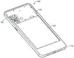
图1是本申请实施例提出的一种电子设备的结构示意图。FIG. 1 is a schematic structural diagram of an electronic device proposed in an embodiment of the present application.

图2是本申请实施例提供的一种电子设备的内部结构示意图。Fig. 2 is a schematic diagram of an internal structure of an electronic device provided by an embodiment of the present application.

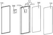
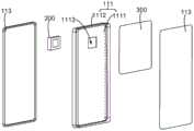
图3是本申请实施例提供的一种电子设备的部分拆分结构示意图。FIG. 3 is a schematic diagram of a partially disassembled structure of an electronic device provided by an embodiment of the present application.

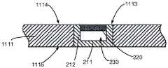
图4是图3提供的一种电子设备的剖面图。FIG. 4 is a cross-sectional view of an electronic device provided in FIG. 3 .

图5是本申请实施例提供的一种扬声器的安装结构示意图。Fig. 5 is a schematic diagram of an installation structure of a loudspeaker provided by an embodiment of the present application.

图6是本申请实施例提供的又一种扬声器的安装结构示意图。Fig. 6 is a schematic diagram of another loudspeaker installation structure provided by the embodiment of the present application.

图7是本申请实施例提供的再一种扬声器的安装结构示意图。Fig. 7 is a schematic diagram of another loudspeaker installation structure provided by the embodiment of the present application.

图8是本申请实施例提供的再又一种扬声器的安装结构示意图。Fig. 8 is a schematic diagram of another loudspeaker installation structure provided by the embodiment of the present application.

图9是本申请实施例提供的另一种电子设备的部分拆分结构示意图。FIG. 9 is a schematic diagram of a partially disassembled structure of another electronic device provided by an embodiment of the present application.

图10是图9提供的一种电子设备的剖面图。FIG. 10 is a cross-sectional view of an electronic device provided in FIG. 9 .

图11是本申请实施例提供的一种扬声器的逻辑框图。Fig. 11 is a logical block diagram of a loudspeaker provided by an embodiment of the present application.

图12是本申请实施例提供的又一种电子设备的部分拆分结构示意图。FIG. 12 is a partially disassembled structural schematic diagram of another electronic device provided by an embodiment of the present application.

图13是图12示出的一种电子设备的剖面图。FIG. 13 is a cross-sectional view of an electronic device shown in FIG. 12 .

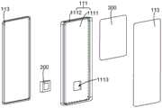
图14是本申请实施例提供的再一种电子设备的部分拆分结构示意图。FIG. 14 is a partially disassembled structural diagram of yet another electronic device provided in an embodiment of the present application.

图15是图14示出的一种电子设备的剖面图。FIG. 15 is a cross-sectional view of an electronic device shown in FIG. 14 .

具体实施方式Detailed ways

下面将结合本申请实施例中的附图,对本申请实施例中的技术方案进行清楚、完整地描述,显然,所描述的实施例仅仅是本申请一部分实施例,而不是全部的实施例。基于本申请中的实施例,本领域普通技术人员在没有作出创造性劳动前提下所获得的所有其他实施例,都属于本申请保护的范围。The following will clearly and completely describe the technical solutions in the embodiments of the application with reference to the drawings in the embodiments of the application. Apparently, the described embodiments are only some of the embodiments of the application, not all of them. Based on the embodiments in this application, all other embodiments obtained by persons of ordinary skill in the art without creative efforts fall within the protection scope of this application.

目前,相关技术中的压电膜发声结构,通常将压电膜贴装在显示屏下方,一般需要多层压电材料堆叠,驱动峰值电压也需要很高,导致总体成本很高;此外,由于压电膜具有频域阻抗特性,其在低频下的音质不佳,即使在很高的电压驱动下,也远远不及传统动圈喇叭。动圈喇叭(扬声器)通常具有一外壳,内部设置振膜,振膜的两侧分别形成前腔和后腔,前腔和后腔分别位于振膜的相背的两侧,在动圈喇叭工作时,振膜在前腔和后腔内振动,形成音频,再通过设置于外壳上的音孔出声。动圈喇叭具有价格便宜,且在中低频频段上音质稳定。At present, the piezoelectric film sounding structure in the related art usually mounts the piezoelectric film under the display screen, generally requires stacking multiple layers of piezoelectric materials, and the driving peak voltage also needs to be high, resulting in a high overall cost; in addition, due to Piezoelectric film has frequency-domain impedance characteristics, and its sound quality at low frequencies is not good. Even when driven by a high voltage, it is far inferior to traditional dynamic speakers. The moving coil speaker (speaker) usually has a shell with a diaphragm inside. The two sides of the diaphragm form a front cavity and a rear cavity respectively. The front cavity and the rear cavity are respectively located on the opposite sides of the diaphragm. At the same time, the diaphragm vibrates in the front cavity and the rear cavity to form audio, and then the sound is emitted through the sound hole on the shell. Dynamic speakers are cheap and have stable sound quality in the mid-low frequency band.

基于此,本申请的发明人提出了本申请各实施例的电子设备100,以期改善上述缺陷。以下结合附图具体描述本申请的各实施例。Based on this, the inventors of the present application propose theelectronic device 100 of various embodiments of the present application in order to improve the above defects. Various embodiments of the present application are described below in detail with reference to the accompanying drawings.

参阅图1,本实施例提供一种电子设备100,本实施例提供的电子设备100,以手机为例进行说明,请一并参阅图1以及图2,电子设备100包括壳体110、显示屏120、主板130、电池140、扬声器200(图3中示出)以及压电膜300等。主板130、电池140设置于壳体110内,主板130与电池140、扬声器200以及压电膜300电连接,以使扬声器200以及压电膜300可以从电池140获得电能并工作。电子设备100具有一长度方向X,沿该长度方向X适于用户直屏握持电子设备100。请再次参阅图1,电子设备100还可以包括前置摄像头170以及麦克风180,在一种实施方式中,前置摄像头170和麦克风180可以设置于电子设备100的沿长度方向X的两端。Referring to FIG. 1, this embodiment provides anelectronic device 100. Theelectronic device 100 provided in this embodiment is described by taking a mobile phone as an example. Please refer to FIG. 1 and FIG. 2 together. Theelectronic device 100 includes ahousing 110, adisplay screen 120, amotherboard 130, abattery 140, a speaker 200 (shown in FIG. 3 ), and apiezoelectric film 300, among others. Themain board 130 and thebattery 140 are arranged in thecasing 110 , themain board 130 is electrically connected with thebattery 140 , thespeaker 200 and thepiezoelectric film 300 , so that thespeaker 200 and thepiezoelectric film 300 can obtain electric energy from thebattery 140 and work. Theelectronic device 100 has a length direction X along which the user is suitable for holding theelectronic device 100 with a straight screen. Please refer to FIG. 1 again. Theelectronic device 100 may further include afront camera 170 and amicrophone 180 .

请参阅图3,壳体110包括中框111以及后盖113,中框111包括中板1111和边框1112,边框1112围设于中板1111的边缘,边框1112突出于中板1111,并且边框1112在中板1111的相背的两侧均突出于中板1111。后盖113装配于中板1111的一侧,且后盖113与边框1112装配固定,后盖113与中框111共同形成容纳腔102,容纳腔102内可以供设置主板130、电池140、麦克风180等各类元器件。边框1112具有相背的内表面和外表面,外表面可以外露作为电子设备100的部分外观面,内表面朝向容纳腔102,内表面和外表面大致呈相互平行的结构。Referring to FIG. 3 , thehousing 110 includes amiddle frame 111 and arear cover 113 , themiddle frame 111 includes amiddle plate 1111 and aframe 1112 , theframe 1112 surrounds the edge of themiddle plate 1111 , theframe 1112 protrudes from themiddle plate 1111 , and theframe 1112 Both opposite sides of themiddle board 1111 protrude from themiddle board 1111 . Theback cover 113 is assembled on one side of themiddle plate 1111, and theback cover 113 and theframe 1112 are assembled and fixed, and theback cover 113 and themiddle frame 111 jointly form the accommodation cavity 102, and themain board 130, thebattery 140, and themicrophone 180 can be installed in the accommodation cavity 102 And other various components. Theframe 1112 has an inner surface and an outer surface opposite to each other. The outer surface can be exposed as a part of the appearance surface of theelectronic device 100 .

中板1111为大致的板状结构,中板1111具有一长度方向,可以理解的是,中板1111的长度方向与电子设备100的长度方向X是一致的。Themiddle plate 1111 has a roughly plate-like structure, and themiddle plate 1111 has a length direction. It can be understood that the length direction of themiddle plate 1111 is consistent with the length direction X of theelectronic device 100 .

请一并结合图3和图4,中板1111具有第一表面1114和第二表面1115,第一表面1114和第二表面1115相背设置,第一表面1114朝向显示屏120,第二表面1115朝向后盖,中板1111设置有连通孔1113,连通孔1113贯穿第一表面1114以及第二表面1115,连通孔1113的轴线方向可以大致与第一表面1114以及第二表面1115相互垂直,在此不做限定。连通孔1113的开设位置可以邻近于中板1111的长度方向的一端,例如邻近于电子设备100的设置前置摄像头170的一端。且连通孔1113的开设位置与边框1112之间的间距可以是1-10mm,在此不做限定。当然,在其他的一些实施方式中,连通孔1113也可以开设于电子设备100的其他位置。连通孔1113可以是圆孔、方形孔或者其他形式的孔,在此不做限定,只需保证连通孔1113的形状结构与扬声器180的形状结构大致相互匹配即可。Please combine with FIG. 3 and FIG. 4 , themiddle plate 1111 has afirst surface 1114 and asecond surface 1115 , thefirst surface 1114 and thesecond surface 1115 are set opposite to each other, thefirst surface 1114 faces thedisplay screen 120 , and thesecond surface 1115 Towards the rear cover, themiddle plate 1111 is provided with acommunication hole 1113, thecommunication hole 1113 runs through thefirst surface 1114 and thesecond surface 1115, the axis direction of thecommunication hole 1113 may be substantially perpendicular to thefirst surface 1114 and thesecond surface 1115, here No limit. The opening position of thecommunication hole 1113 may be adjacent to one end of themiddle plate 1111 in the length direction, for example, adjacent to an end of theelectronic device 100 where thefront camera 170 is disposed. And the distance between the open position of thecommunication hole 1113 and theframe 1112 may be 1-10 mm, which is not limited here. Certainly, in some other implementation manners, thecommunication hole 1113 may also be opened in other positions of theelectronic device 100 . Thecommunication hole 1113 may be a round hole, a square hole or other types of holes, which are not limited here, and it is only necessary to ensure that the shape and structure of thecommunication hole 1113 roughly match the shape and structure of thespeaker 180 .

显示屏120装配于边框1112,且显示屏120与中板1111的第一表面1114相对,显示屏120的朝向中板1111的表面与显示屏120的第一表面1114之间形成间隙121,间隙121内填充有空气,连通孔1113与间隙121连通。间隙121的宽度过宽会导致电子设备100的厚度增大,不利于电子设备100的轻薄化;而间隙121的宽度过小,又会限制后续安装扬声器后,扬声器的工作。示例性地,间隙121的宽度例如可以是0.18mm-0.22mm,也即是第一表面1114与显示屏120之间的间距为0.18mm-0.22mm,当然,间隙121的宽度也可以是其他数值,在此不做限定。Thedisplay screen 120 is assembled on theframe 1112, and thedisplay screen 120 is opposite to thefirst surface 1114 of themiddle board 1111, and agap 121 is formed between the surface of thedisplay screen 120 facing themiddle board 1111 and thefirst surface 1114 of thedisplay screen 120, thegap 121 The interior is filled with air, and thecommunication hole 1113 communicates with thegap 121 . If the width of thegap 121 is too wide, the thickness of theelectronic device 100 will increase, which is not conducive to the thinning of theelectronic device 100; if the width of thegap 121 is too small, it will limit the work of the speaker after the speaker is installed. Exemplarily, the width of thegap 121 can be 0.18mm-0.22mm, that is, the distance between thefirst surface 1114 and thedisplay screen 120 is 0.18mm-0.22mm, of course, the width of thegap 121 can also be other values , is not limited here.

显示屏120可以采用LCD(Liquid Crystal Display,液晶显示)屏用于显示信息,LCD屏可以为TFT(Thin Film Transistor,薄膜晶体管)屏幕或IPS(In-Plane Switching,平面转换)屏幕或SLCD(Splice Liquid Crystal Display,拼接专用液晶显示)屏幕。在另一些实施例中,显示屏120可以采用OLED(Organic Light-EmittingDiode,有机电激光显示)屏用于显示信息,OLED屏可以为AMOLED(Active Matrix OrganicLight EmittingDiode,有源矩阵有机发光二极体)屏幕或Super AMOLED(Super ActiveMatrix OrganicLight Emitting Diode,超级主动驱动式有机发光二极体)屏幕或SuperAMOLED Plus(Super Active Matrix Organic Light Emitting Diode Plus,魔丽屏)屏幕,此处不再赘述。Display screen 120 can adopt LCD (Liquid Crystal Display, liquid crystal display) screen to be used for displaying information, and LCD screen can be TFT (Thin Film Transistor, thin film transistor) screen or IPS (In-Plane Switching, plane conversion) screen or SLCD (Splice Liquid Crystal Display, splicing dedicated liquid crystal display) screen. In some other embodiments, thedisplay screen 120 may use an OLED (Organic Light-Emitting Diode, organic electro-laser display) screen for displaying information, and the OLED screen may be an AMOLED (Active Matrix Organic Light Emitting Diode, active matrix organic light-emitting diode) Screen or Super AMOLED (Super ActiveMatrix Organic Light Emitting Diode, super active driving type organic light emitting diode) screen or SuperAMOLED Plus (Super Active Matrix Organic Light Emitting Diode Plus, magic screen) screen, no more details here.

电池140和主板130均设置于容纳腔102内,并承载于中板1111,且由后盖113遮盖形成保护。电池140与主板130电性连接,以控制电池140向其他功能元件供电或者获取电池140的电量等信息。Both thebattery 140 and themain board 130 are disposed in the accommodating cavity 102 , carried on themiddle board 1111 , and covered by therear cover 113 to form protection. Thebattery 140 is electrically connected to themain board 130 to control thebattery 140 to supply power to other functional components or obtain information such as the power of thebattery 140 .

请继续参阅图4,扬声器200设置于中板1111,具体而言,扬声器200包括外壳210和振膜220,振膜220设置于外壳210并从外壳210外露,即振膜220是部分开放式的,并未完全被外壳210封装。请一并参阅图4和图5,外壳210包括侧壳212和底壳211,侧壳212连接于底壳211的边缘,侧壳212和底壳211围成一腔体,振膜220安装于侧壳212并部分露出外壳210,振膜220与底壳211之间形成后腔230,后腔230可以作为振膜220工作时的一部分工作空间,振膜220在振动时可以朝向后腔230方向形变。侧壳212安装于中板1111并对连通孔1113形成密封,使得连通孔1113和间隙121形成的空间为一封闭空间,振膜220与连通孔1113的位置对应,此时由于振膜220是相对于外壳210呈开放式的,因此间隙121可以作为振膜220的前腔,当振膜220朝向间隙121方向振动时,填充于间隙121内的空气振动,带动显示屏120振动,从而发声。这种实施方式,不需要在外壳210的显示屏120一侧开孔,也不需要在显示屏120上开孔,保证了电子设备100的设置显示屏120的一侧的外观一致性。Please continue to refer to FIG. 4 , theloudspeaker 200 is arranged on themiddle plate 1111, specifically, theloudspeaker 200 includes acasing 210 and adiaphragm 220, and thediaphragm 220 is arranged on thecasing 210 and exposed from thecasing 210, that is, thediaphragm 220 is partially open , is not completely encapsulated by theshell 210 . Please refer to FIG. 4 and FIG. 5 together. Theshell 210 includes aside shell 212 and abottom shell 211. Theside shell 212 is connected to the edge of thebottom shell 211. Theside shell 212 and thebottom shell 211 form a cavity, and thediaphragm 220 is mounted on Theside shell 212 partly exposes theshell 210, and therear cavity 230 is formed between thediaphragm 220 and thebottom shell 211. Therear cavity 230 can be used as a part of the working space of thediaphragm 220 when it is working, and thediaphragm 220 can face the direction of therear cavity 230 when vibrating. deformation. Theside shell 212 is installed on themiddle plate 1111 and seals thecommunication hole 1113, so that the space formed by thecommunication hole 1113 and thegap 121 is a closed space, and the position of thediaphragm 220 corresponds to the position of thecommunication hole 1113. At this time, since thediaphragm 220 is opposite to the Since theshell 210 is open, thegap 121 can be used as the front cavity of thediaphragm 220. When thediaphragm 220 vibrates toward thegap 121, the air filled in thegap 121 vibrates, driving thedisplay screen 120 to vibrate, thereby producing sound. In this embodiment, there is no need to open holes on the side of thedisplay screen 120 of thehousing 210 , and there is no need to open holes on thedisplay screen 120 , which ensures the appearance consistency of the side of theelectronic device 100 where thedisplay screen 120 is installed.

其中,在扬声器200处于非工作状态时,请继续参阅图5,振膜220可以与第二表面1115保持平齐,此时,振膜220工作过程中,可以利用连通孔1113以及间隙121作为前腔,这种设置方式的好处在于,由于连通孔1113的孔径较小,在振膜220向前腔振动时,连通孔1113内的空气受到振动驱动,具有较大的振幅,在振动能量传递至间隙121内时,振动在整个间隙121内沿显示屏120的平面方向传播的时间更为充裕,因此带动显示屏120振动的振动能量在显示屏120的各点分布更为均匀,在显示屏120振动发声的过程中,形成的音质均衡性更佳。Wherein, when thespeaker 200 is in a non-working state, please continue to refer to FIG. 5 , thediaphragm 220 can be kept flush with thesecond surface 1115. At this time, during the working process of thediaphragm 220, thecommunication hole 1113 and thegap 121 can be used as front cavity, the benefit of this arrangement is that, due to the smaller aperture of thecommunication hole 1113, when thediaphragm 220 vibrates to the front cavity, the air in thecommunication hole 1113 is driven by the vibration and has a larger amplitude. When in thegap 121, the time for the vibration to propagate along the plane direction of thedisplay screen 120 in theentire gap 121 is more abundant, so the vibration energy that drives thedisplay screen 120 to vibrate is distributed more evenly at each point of thedisplay screen 120, and the vibration energy on thedisplay screen 120 In the process of vibrating and sounding, the sound quality formed is better balanced.

如图6所示,在扬声器200处于非工作状态时,振膜220也可以与第一表面1114保持平齐,此时,振膜220工作过程中,以及间隙121作为前腔,这种设置方式的好处在于,振膜220的振动可以直接传递至间隙121内,振动能量的损耗较小,振动在整个间隙121内沿显示屏120的平面方向传播时,振动传递至显示屏120时依然保持较大的振动能力,因此带动显示屏120振动的振动能量更大,提高响度。对于动圈扬声器200而言,其在中高频频段的响度不足,通过将振膜220设置为与第一表面1114保持平齐的形式,增大振动能量,可以提高扬声器200在中高频频段的响度。As shown in Figure 6, when thespeaker 200 is in a non-working state, thediaphragm 220 can also be kept flush with thefirst surface 1114. At this time, during the working process of thediaphragm 220, and thegap 121 is used as the front cavity, this arrangement The advantage is that the vibration of thediaphragm 220 can be directly transmitted to thegap 121, and the loss of vibration energy is relatively small. Large vibration capacity, so the vibration energy that drives thedisplay screen 120 to vibrate is greater, increasing the loudness. For thedynamic speaker 200, its loudness in the middle and high frequency bands is insufficient. By setting thediaphragm 220 in a form flush with thefirst surface 1114 and increasing the vibration energy, the loudness of thespeaker 200 in the middle and high frequency bands can be improved. .

在另一种实施方式中,参阅图7,在扬声器200处于非工作状态时,振膜220也可以位于连通孔1113内,此时扬声器200可以保证较好的响度,又可以使得显示屏120在振动发声的过程中,具有较好的音质均衡性。可以理解的是,在另外的一些实施方式中,在扬声器200处于非工作状态时,振膜220也可以位于间隙121内,在此不做具体限定。In another embodiment, referring to FIG. 7 , when thespeaker 200 is in a non-working state, thediaphragm 220 can also be located in thecommunication hole 1113. At this time, thespeaker 200 can ensure a better loudness, and thedisplay screen 120 can In the process of vibrating and sounding, it has better sound quality balance. It can be understood that, in some other implementation manners, when thespeaker 200 is in a non-working state, thediaphragm 220 may also be located in thegap 121 , which is not specifically limited here.

侧壳212可以直接通过粘接的方式设置于中板1111的第二表面1115,保证振膜220可以与连通孔1113对应即可,此时连通孔1113的孔径可以略小于侧壳212的外径,侧壳212连接第二表面1115后可以封闭连通孔1113,使得振膜220朝前腔振动时,振动能量不会向容纳腔内损耗。侧壳212还可以通过注塑方式与中板1111一体结合,这样可以较好的固定扬声器200的位置,防止在扬声器200工作过程中,因振动导致扬声器200发生移位现象。在另一种实施方式中,连通孔1113的孔径可以相比于扬声器200的尺寸设置得略大一些,侧壳212嵌入连通孔1113并固定连接于中板1111,例如通过粘接的方式与中板1111固定,还可以通过过盈卡接的方式与中板1111相对固定。此外,侧壳212与围成连通孔1113的孔壁之间可以通过胶水、泡棉等实现密封,进而使得间隙121形成一密闭的腔体,提高振动发声效果。Theside shell 212 can be directly mounted on thesecond surface 1115 of themiddle plate 1111 by bonding, so that thediaphragm 220 can correspond to thecommunication hole 1113. At this time, the diameter of thecommunication hole 1113 can be slightly smaller than the outer diameter of theside shell 212. After theside shell 212 is connected to thesecond surface 1115, thecommunication hole 1113 can be closed, so that when thediaphragm 220 vibrates toward the front cavity, the vibration energy will not be lost into the receiving cavity. Theside shell 212 can also be integrally combined with themiddle plate 1111 by injection molding, so that the position of thespeaker 200 can be better fixed and thespeaker 200 can be prevented from being displaced due to vibration during the working process of thespeaker 200 . In another embodiment, the aperture of thecommunication hole 1113 can be set slightly larger than the size of thespeaker 200, and theside shell 212 is embedded in thecommunication hole 1113 and fixedly connected to themiddle plate 1111, for example, by bonding with the middle plate. Theplate 1111 is fixed, and can also be relatively fixed with themiddle plate 1111 by way of interference clamping. In addition, glue, foam, etc. can be used to seal between theside shell 212 and the wall surrounding thecommunication hole 1113 , so that thegap 121 forms a closed cavity to improve the vibration and sound generation effect.

在又一种实施方式中,参阅图8,第二表面1115设置有安装槽1116,安装槽1116的外径可以略大于外壳210的外径,连通孔1113位于安装槽1116内,侧壳212至少部分嵌入安装槽1116内并连接于中板1111形成固定,振膜220与连通孔1113对应即可。这种实施方式的好处在于:可以使得扬声器200与显示屏120的间距缩小,一方面降低电子设备100的厚度,另一方面也可以达到提高扬声器200的响度的效果。In yet another embodiment, referring to FIG. 8, thesecond surface 1115 is provided with a mountinggroove 1116, the outer diameter of the mountinggroove 1116 may be slightly larger than the outer diameter of thehousing 210, thecommunication hole 1113 is located in the mountinggroove 1116, and theside shell 212 is at least A part is embedded in theinstallation groove 1116 and connected to themiddle plate 1111 to form a fixation, and thediaphragm 220 is only required to correspond to thecommunication hole 1113 . The advantage of this embodiment is that the distance between thespeaker 200 and thedisplay screen 120 can be reduced, on the one hand, the thickness of theelectronic device 100 can be reduced, and on the other hand, the loudness of thespeaker 200 can also be improved.

压电膜300即压电薄膜,其利用施加于压电薄膜上的交替变化的电压,使得压电薄膜22内部晶体状态发生变化,进而使压电薄膜将会产生形变,当压电薄膜伸展时,压电薄膜向上弯曲,当压电薄膜收缩时,压电薄膜向下弯曲,进而产生振动并反复推动显示屏120从而发出声音。具体到本实施例中,压电膜300在接收电信号时将电信号转换为机械振动。压电膜300设置于显示屏120的任意位置,压电膜300贴设于显示屏120的下方,当压电膜300不工作时,位于显示屏120和中板1111之间,当压电膜300振动时,可以带动显示屏120振动进而实现发声。Thepiezoelectric film 300 is a piezoelectric film, which utilizes the alternating voltage applied to the piezoelectric film to change the internal crystal state of the piezoelectric film 22, thereby causing the piezoelectric film to deform. When the piezoelectric film stretches , the piezoelectric film bends upwards, and when the piezoelectric film shrinks, the piezoelectric film bends downwards, thereby generating vibrations and repeatedly pushing thedisplay screen 120 to produce sound. Specifically in this embodiment, thepiezoelectric film 300 converts the electrical signal into mechanical vibration when receiving the electrical signal. Thepiezoelectric film 300 is arranged at any position of thedisplay screen 120, and thepiezoelectric film 300 is attached to the bottom of thedisplay screen 120. When thepiezoelectric film 300 is not working, it is located between thedisplay screen 120 and themiddle plate 1111. When the piezoelectric film When the 300 vibrates, thedisplay screen 120 can be driven to vibrate to realize sound generation.

本实施例中,请再次参阅图3和图4,扬声器设置于中板1111的长度方向的一端,压电膜300邻近于中板1111的长度方向的另一端,且压电膜300与扬声器200可以是相互错开的,压电膜300覆盖显示屏120的面积例如可以小于等于显示屏120的面积的50%,扬声器和压电膜300彼此位于电子设备100的长度方向的两端,这种设置方式,当扬声器和压电膜300工作时,两者的间距相对较远,可以在电子设备100的各个位置均可以由较好的音质。其中,扬声器200可以设置于电子设备100的顶部,压电膜300可以设置于电子设备100的底部,顶部和底部是指电子设备100的长度方向的两端,且通常在用户使用电子设备100的过程中,顶部位于上方,底部位于下方,且电子设备100的顶部还可以设置前置摄像头等零部件,即扬声器200与前置摄像头位于电子设备100的长度方向的同一端。In this embodiment, please refer to FIG. 3 and FIG. 4 again, the speaker is arranged at one end of the length direction of themiddle plate 1111, thepiezoelectric film 300 is adjacent to the other end of the length direction of themiddle plate 1111, and thepiezoelectric film 300 and thespeaker 200 It can be staggered from each other, the area covered by thepiezoelectric film 300 can be less than or equal to 50% of the area of thedisplay screen 120, for example, the speaker and thepiezoelectric film 300 are located at both ends of the length direction of theelectronic device 100, this arrangement In this way, when the loudspeaker and thepiezoelectric film 300 are working, the distance between them is relatively far, so that better sound quality can be obtained at various positions of theelectronic device 100 . Wherein, thespeaker 200 can be arranged on the top of theelectronic device 100, and thepiezoelectric film 300 can be arranged on the bottom of theelectronic device 100. During the process, the top is at the top and the bottom is at the bottom, and the top of theelectronic device 100 can also be provided with components such as a front camera, that is, thespeaker 200 and the front camera are located at the same end of theelectronic device 100 in the length direction.

为了加强显示屏120的散热,显示屏120的朝向中板1111的表面还可以设置石墨层400,石墨层400贴设于显示屏120,且位于显示屏120设置压电膜300以外的区域,在一些实施方式中,石墨层400可以与压电膜300共面设置。In order to enhance the heat dissipation of thedisplay screen 120, agraphite layer 400 can also be provided on the surface of thedisplay screen 120 facing themiddle plate 1111. In some embodiments, thegraphite layer 400 can be coplanar with thepiezoelectric film 300 .

在另一种实施方式中,参阅图9和图10,还可以完全取消石墨层400,将压电膜300的覆盖面积提高至占显示屏120的面积的90%以上,这样可以显著的提高压电膜300振动时驱动显示屏120发声的音量和音质。并且此时,扬声器200可以与压电膜300处于相对的状态,当扬声器200发声时,且当仅扬声器200一者工作时,振动能量可以传递至压电膜300上,在经过压电膜300的振动后传递至显示屏120,可以实现音质的滤过增强,降低音量提高隐私性。当然,需要说明的是,压电膜300占显示屏120的面积的比例也可以是其他数值,在此不做限定。In another embodiment, referring to FIG. 9 and FIG. 10 , thegraphite layer 400 can also be completely eliminated, and the coverage area of thepiezoelectric film 300 can be increased to more than 90% of the area of thedisplay screen 120, which can significantly increase the voltage. The volume and sound quality of the sound produced by thedisplay screen 120 when theelectric film 300 vibrates. And at this moment, thespeaker 200 can be in the opposite state with thepiezoelectric film 300, when thespeaker 200 makes a sound, and when only thespeaker 200 is working, the vibration energy can be transmitted to thepiezoelectric film 300, and after passing through thepiezoelectric film 300 After the vibration is transmitted to thedisplay screen 120, the sound quality can be filtered and enhanced, and the volume can be reduced to improve privacy. Of course, it should be noted that the ratio of thepiezoelectric film 300 to the area of thedisplay screen 120 may also be other values, which are not limited here.

本实施例中的电子设备100,不需要设置受话器,也不需要在外壳210的显示屏120一侧开孔,利用显示屏120与中板1111之间的间隙121,作为扬声器200的前腔,通过振膜220的振动带动显示屏120振动发声,既保证了电子设备100的外观的一致性,又降低了电子设备100的成本。为了进一步地提高用户在使用电子设备100进行通话等应用场景下的效果,扬声器200可以设置于电子设备100的顶部,也即是设置于中板1111的顶部,电子设备100的顶部是指电子设备100长度方向的端部,并邻近于边框。当然,在其他的一些实施方式中,扬声器200也可以设置于中板1111的其他任意位置,本实施例对此不做限定。Theelectronic device 100 in this embodiment does not need to be provided with a receiver, nor does it need to open a hole on the side of thedisplay screen 120 of thehousing 210. Thegap 121 between thedisplay screen 120 and themiddle plate 1111 is used as the front cavity of thespeaker 200. Vibration of thediaphragm 220 drives thedisplay screen 120 to vibrate and produce sound, which not only ensures the consistency of the appearance of theelectronic device 100 , but also reduces the cost of theelectronic device 100 . In order to further improve the effect of the user in application scenarios such as using theelectronic device 100 to make a call, thespeaker 200 can be arranged on the top of theelectronic device 100, that is, on the top of themiddle board 1111. The top of theelectronic device 100 refers to the 100 at the end in the length direction and adjacent to the frame. Certainly, in some other implementation manners, theloudspeaker 200 may also be disposed at any other position of themiddle board 1111 , which is not limited in this embodiment.

需要说明的是,扬声器200和压电膜300可以彼此独立的播放高频、中频或者低频的音频信号,在此不做限定。本实施例中,参阅图11,为了提高电子设备100的音质,主板130集成或者设置有控制部131、驱动电路132、第一功率放大器133和第二功率放大器134,控制部131与驱动电路132、第一功率放大器133以及第二功率放大器134电连接,控制部131通过驱动电路132控制第一功率放大器133以及第二功率放大器134工作,控制部131对音频信号进行模数转换后,通过驱动电路132将信号发送至第一功率放大器133和/或第二功率放大器134,第一功率放大器133放大后发送至扬声器200,并由扬声器200转换为音频信号,振膜220在前腔以及后腔230内振动,带动显示屏振动发声。或者经第二功率放大器134放大后发送至压电膜300,并由压电膜300振动发声。具体而言,控制部131例如可以是微控制单元、中央处理器等。驱动电路132可以包括串行总线和音频总线,控制部131电连接串行总线和音频总线,当控制部131接收数字音频信号后,通过音频总线和串行总线,经模数转换和功率放大后输出到扬声器200,扬声器200的振膜220振动,带动显示屏120振动发声。It should be noted that theloudspeaker 200 and thepiezoelectric film 300 can independently play high-frequency, medium-frequency or low-frequency audio signals, which is not limited herein. In this embodiment, referring to FIG. 11 , in order to improve the sound quality of theelectronic device 100, themain board 130 is integrated or provided with acontrol unit 131, adrive circuit 132, afirst power amplifier 133 and asecond power amplifier 134, and thecontrol unit 131 and thedrive circuit 132 , thefirst power amplifier 133 and thesecond power amplifier 134 are electrically connected, thecontrol unit 131 controls thefirst power amplifier 133 and thesecond power amplifier 134 to work through thedrive circuit 132, and after thecontrol unit 131 performs analog-to-digital conversion on the audio signal, it is driven Thecircuit 132 sends the signal to thefirst power amplifier 133 and/or thesecond power amplifier 134, thefirst power amplifier 133 amplifies and sends it to thespeaker 200, and is converted into an audio signal by thespeaker 200, thediaphragm 220 is in the front cavity and the rear cavity Vibration within 230, drives the display screen to vibrate and make sound. Or it is amplified by thesecond power amplifier 134 and sent to thepiezoelectric film 300 , and thepiezoelectric film 300 vibrates to generate sound. Specifically, thecontrol unit 131 may be, for example, a micro control unit, a central processing unit, or the like. The drivingcircuit 132 may include a serial bus and an audio bus, and thecontrol unit 131 is electrically connected to the serial bus and the audio bus. After thecontrol unit 131 receives the digital audio signal, it passes through the audio bus and the serial bus, and undergoes analog-to-digital conversion and power amplification. The output is sent to thespeaker 200, and thediaphragm 220 of thespeaker 200 vibrates, driving thedisplay screen 120 to vibrate and produce sound.

在一种应用场景中,在第一音频播放模式下,例如用户需要使用电子设备100接听电话、语音通话等,此时需要提高通话的隐私性。控制部131可以通过驱动电路132控制第一功率放大器133工作。具体而言,控制部131对音频信号进行模数转换后,通过驱动电路132将信号发送至第一功率放大器133,第一功率放大器133放大后发送至扬声器200,并由扬声器200转换为音频信号,振膜220在前腔以及后腔内振动,带动显示屏振动发声。In an application scenario, in the first audio playback mode, for example, the user needs to use theelectronic device 100 to answer calls, voice calls, etc., and at this time, the privacy of the call needs to be improved. Thecontrol unit 131 can control thefirst power amplifier 133 to work through the drivingcircuit 132 . Specifically, after thecontrol unit 131 performs analog-to-digital conversion on the audio signal, the signal is sent to thefirst power amplifier 133 through the drivingcircuit 132, and thefirst power amplifier 133 amplifies it and sends it to thespeaker 200, and thespeaker 200 converts the signal into an audio signal , thediaphragm 220 vibrates in the front cavity and the rear cavity, driving the display screen to vibrate and produce sound.

在另一种应用场景中,在第二音频播放模式下,例如用户在使用电子设备100进行外放时,控制部131可以通过驱动电路132控制第一功率放大器133以及第二功率放大器134工作。具体而言,控制部131对音频信号进行模数转换后,通过驱动电路132将中低频信号发送至第一功率放大器133,将中高频信号发送至第二功率放大器134,第一功率放大器133放大后发送至扬声器200,并由扬声器200转换为音频信号振膜220在前腔以及后腔内振动,带动显示屏振动发声。经第二功率放大器134放大后的音频信号发送至压电膜300,并由压电膜300振动,带动显示屏120振动发声。这样由扬声器200生成的中低频信号和由压电膜300生成的中高频信号在传播时叠加,覆盖全频段,使得外放音质更好。In another application scenario, in the second audio playback mode, for example, when the user uses theelectronic device 100 for playback, thecontrol unit 131 can control thefirst power amplifier 133 and thesecond power amplifier 134 to work through the drivingcircuit 132 . Specifically, after thecontrol unit 131 performs analog-to-digital conversion on the audio signal, the mid-low frequency signal is sent to thefirst power amplifier 133 through the drivingcircuit 132, and the mid-high frequency signal is sent to thesecond power amplifier 134, and thefirst power amplifier 133 amplifies After that, it is sent to thespeaker 200, and converted into an audio signal by thespeaker 200. Thediaphragm 220 vibrates in the front cavity and the rear cavity, driving the display screen to vibrate and produce sound. The audio signal amplified by thesecond power amplifier 134 is sent to thepiezoelectric film 300, and thepiezoelectric film 300 vibrates to drive thedisplay screen 120 to vibrate and produce sound. In this way, the mid-low frequency signal generated by theloudspeaker 200 and the mid-high frequency signal generated by thepiezoelectric film 300 are superimposed during transmission, covering the entire frequency range, so that the sound quality of the external playback is better.

在另一种实施方式中,请一并参阅图12和图13,扬声器200可以设置于电子设备100的底部,压电膜300可以设置于电子设备100的顶部,顶部和底部是指电子设备100的长度方向的两端,且通常在用户使用电子设备100的过程中,顶部位于上方,底部位于下方,且电子设备100的顶部还可以设置前置摄像头等零部件,即压电膜300与前置摄像头位于电子设备100的长度方向的同一端,扬声器200与前置摄像头位于电子设备100的长度方向的相对的一端。In another embodiment, please refer to FIG. 12 and FIG. 13 together. Thespeaker 200 can be arranged on the bottom of theelectronic device 100, and thepiezoelectric film 300 can be arranged on the top of theelectronic device 100. The top and the bottom refer to theelectronic device 100. The two ends of the length direction of theelectronic device 100, and usually when the user uses theelectronic device 100, the top is at the top and the bottom is at the bottom, and the top of theelectronic device 100 can also be equipped with components such as a front camera, that is, thepiezoelectric film 300 and the front The camera is located at the same end of theelectronic device 100 in the length direction, and thespeaker 200 and the front camera are located at the opposite end of theelectronic device 100 in the length direction.

此时,在一种应用场景中,在第一音频播放模式下,例如用户需要使用电子设备100接听电话、语音通话等,此时需要提高通话的隐私性。控制部131可以通过驱动电路132控制第二功率放大器134工作。具体而言,控制部131对音频信号进行模数转换后,通过驱动电路132将信号发送至第二功率放大器134,第二功率放大器134放大后发送至压电膜300,并由压电膜300转换为音频信号,压电膜300振动,带动显示屏120振动发声。At this time, in an application scenario, in the first audio playback mode, for example, the user needs to use theelectronic device 100 to answer calls, make voice calls, etc., and at this time it is necessary to improve the privacy of the call. Thecontrol unit 131 can control thesecond power amplifier 134 to work through the drivingcircuit 132 . Specifically, after thecontrol unit 131 performs analog-to-digital conversion on the audio signal, the signal is sent to thesecond power amplifier 134 through the drivingcircuit 132, and thesecond power amplifier 134 sends the signal to thepiezoelectric film 300 after being amplified, and thepiezoelectric film 300 Converted into an audio signal, thepiezoelectric film 300 vibrates, driving thedisplay screen 120 to vibrate and produce sound.

在另一种应用场景中,在第二音频播放模式下,例如用户在使用电子设备100进行外放时,控制部131可以通过驱动电路132控制第一功率放大器133以及第二功率放大器134工作。具体而言,控制部131对音频信号进行模数转换后,通过驱动电路132将中低频信号发送至第一功率放大器133,将中高频信号发送至第二功率放大器134,第一功率放大器133放大后发送至扬声器200,并由扬声器200转换为音频信号振膜220在前腔以及后腔内振动,带动显示屏振动发声。经第二功率放大器134放大后的音频信号发送至压电膜300,并由压电膜300振动,带动显示屏120振动发声。这样由扬声器200生成的中低频信号和由压电膜300生成的中高频信号在传播时叠加,覆盖全频段,使得外放音质更好。In another application scenario, in the second audio playback mode, for example, when the user uses theelectronic device 100 for playback, thecontrol unit 131 can control thefirst power amplifier 133 and thesecond power amplifier 134 to work through the drivingcircuit 132 . Specifically, after thecontrol unit 131 performs analog-to-digital conversion on the audio signal, the mid-low frequency signal is sent to thefirst power amplifier 133 through the drivingcircuit 132, and the mid-high frequency signal is sent to thesecond power amplifier 134, and thefirst power amplifier 133 amplifies After that, it is sent to thespeaker 200, and converted into an audio signal by thespeaker 200. Thediaphragm 220 vibrates in the front cavity and the rear cavity, driving the display screen to vibrate and produce sound. The audio signal amplified by thesecond power amplifier 134 is sent to thepiezoelectric film 300, and thepiezoelectric film 300 vibrates to drive thedisplay screen 120 to vibrate and produce sound. In this way, the mid-low frequency signal generated by theloudspeaker 200 and the mid-high frequency signal generated by thepiezoelectric film 300 are superimposed during transmission, covering the entire frequency range, so that the sound quality of the external playback is better.

在另一种实施方式中,请一并参阅图14和图15,扬声器200和压电膜300还可以设置于电子设备100的长度方向X的同一端,例如扬声器200和压电膜300同时位于电子设备100的顶部,此时,扬声器200和压电膜300可以相对,即压电膜300在中板1111的投影覆盖连通孔1113,当扬声器200发声时,且当仅扬声器200一者工作时,振动能量可以传递至压电膜300上,在经过压电膜300的振动后传递至显示屏120,可以实现音质的滤过增强,降低音量提高隐私性。In another embodiment, please refer to FIG. 14 and FIG. 15 together. Thespeaker 200 and thepiezoelectric film 300 can also be arranged at the same end of theelectronic device 100 in the longitudinal direction X, for example, thespeaker 200 and thepiezoelectric film 300 are located at the same time. The top of theelectronic device 100, at this time, thespeaker 200 and thepiezoelectric film 300 can be opposite, that is, the projection of thepiezoelectric film 300 on themiddle plate 1111 covers thecommunication hole 1113, when thespeaker 200 is sounding, and when only thespeaker 200 is working , the vibration energy can be transmitted to thepiezoelectric film 300, and then transmitted to thedisplay screen 120 after being vibrated by thepiezoelectric film 300, so that the sound quality can be filtered and enhanced, and the volume can be reduced to improve privacy.

请再次结合图11,为了提高电子设备100的音质,主板130集成或者设置有控制部131、驱动电路132、第一功率放大器133和第二功率放大器134,控制部131与驱动电路132、第一功率放大器133以及第二功率放大器134电连接,控制部131通过驱动电路132控制第一功率放大器133以及第二功率放大器134工作,控制部131对音频信号进行模数转换后,通过驱动电路132将信号发送至第一功率放大器133和/或第二功率放大器134,第一功率放大器133放大后发送至扬声器200,并由扬声器200转换为音频信号,振膜220在前腔以及后腔230内振动,带动显示屏振动发声。或者经第二功率放大器134放大后发送至压电膜300,并由压电膜300振动,带动显示屏120振动发声。具体而言,控制部131例如可以是是微控制单元、中央处理器等。驱动电路132可以包括串行总线和音频总线,控制部131电连接串行总线和音频总线,当控制部131接收数字音频信号后,通过音频总线和串行总线,经模数转换和功率放大后输出到扬声器200,扬声器200的振膜220振动,带动显示屏120振动发声。Please refer to FIG. 11 again. In order to improve the sound quality of theelectronic device 100, themain board 130 is integrated or provided with acontrol unit 131, adrive circuit 132, afirst power amplifier 133 and asecond power amplifier 134. Thecontrol unit 131 and thedrive circuit 132, the first Thepower amplifier 133 and thesecond power amplifier 134 are electrically connected, and thecontrol unit 131 controls the operation of thefirst power amplifier 133 and thesecond power amplifier 134 through the drivingcircuit 132. The signal is sent to thefirst power amplifier 133 and/or thesecond power amplifier 134, thefirst power amplifier 133 is amplified and sent to thespeaker 200, and is converted into an audio signal by thespeaker 200, and thediaphragm 220 vibrates in the front cavity and therear cavity 230 , to drive the display to vibrate and sound. Or it is amplified by thesecond power amplifier 134 and sent to thepiezoelectric film 300, and thepiezoelectric film 300 vibrates to drive thedisplay screen 120 to vibrate and produce sound. Specifically, thecontrol unit 131 may be, for example, a micro control unit, a central processing unit, or the like. The drivingcircuit 132 may include a serial bus and an audio bus, and thecontrol unit 131 is electrically connected to the serial bus and the audio bus. After thecontrol unit 131 receives the digital audio signal, it passes through the audio bus and the serial bus, and undergoes analog-to-digital conversion and power amplification. The output is sent to thespeaker 200, and thediaphragm 220 of thespeaker 200 vibrates, driving thedisplay screen 120 to vibrate and produce sound.

在一种应用场景中,在第一音频播放模式下,例如用户需要使用电子设备100接听电话、语音通话等,此时可以进入听筒模式,提高通话的隐私性。具体而言,控制部131可以通过驱动电路132控制第一功率放大器133以及第二功率放大器134工作。具体而言,控制部131对音频信号进行模数转换后,通过驱动电路132将中低频信号发送至第一功率放大器133,将中高频信号发送至第二功率放大器134,第一功率放大器133放大后发送至扬声器200,并由扬声器200转换为音频信号振膜220在前腔以及后腔内振动,带动显示屏振动发声。经第二功率放大器134放大后的音频信号发送至压电膜300,并由压电膜300振动,带动显示屏120振动发声。而用户使用时,电子设备100靠近耳部,因此离电子设备100相对较远的其他人很难同时听到中低频音频信号和中高频音频信号,因此隐私性更高,而用户的耳部可以同时接收到中低频的的音频信号以及中高频的音频信号,这样便可以提高电子设备100在使用时的隐私保护性。In one application scenario, in the first audio playback mode, for example, the user needs to use theelectronic device 100 to answer calls, voice calls, etc., at this time, the user can enter the handset mode to improve the privacy of the call. Specifically, thecontrol unit 131 can control thefirst power amplifier 133 and thesecond power amplifier 134 to work through the drivingcircuit 132 . Specifically, after thecontrol unit 131 performs analog-to-digital conversion on the audio signal, the mid-low frequency signal is sent to thefirst power amplifier 133 through the drivingcircuit 132, and the mid-high frequency signal is sent to thesecond power amplifier 134, and thefirst power amplifier 133 amplifies After that, it is sent to thespeaker 200, and converted into an audio signal by thespeaker 200. Thediaphragm 220 vibrates in the front cavity and the rear cavity, driving the display screen to vibrate and produce sound. The audio signal amplified by thesecond power amplifier 134 is sent to thepiezoelectric film 300, and thepiezoelectric film 300 vibrates to drive thedisplay screen 120 to vibrate and produce sound. When the user uses it, theelectronic device 100 is close to the ear, so it is difficult for other people who are relatively far away from theelectronic device 100 to hear the mid-low frequency audio signal and the mid-high frequency audio signal at the same time, so the privacy is higher, and the user's ear can At the same time, the medium and low frequency audio signals and the medium and high frequency audio signals are received, so that the privacy protection of theelectronic device 100 during use can be improved.

当用户需要在相对嘈杂的环境中使用电子设备100接听电话、语音通话时,此时需要进一步的加大振动音量,此时可以通过进入超级音量模式实现,超级音量模式可以在常规的听筒模式的基础上加大音量。此时可以通过进一步地同时增大第一功率放大器133和第二功率放大器134的放大倍数,第一功率放大器133放大后发送至扬声器200,并由扬声器200转换为音频信号振膜220在前腔以及后腔内振动,带动显示屏振动发声。经第二功率放大器134放大后的音频信号发送至压电膜300,并由压电膜300振动,带动显示屏120振动发声。用户可以通过输入控制指令,进一步提高振动强度,提高音量。例如:用户可以通过按压电子设备的“音量+”按键,触发超级音量模式。当然,也可以通过在显示屏上进行操作进入超级音量模式,在此不做限定。When the user needs to use theelectronic device 100 to answer calls or voice calls in a relatively noisy environment, it is necessary to further increase the vibration volume at this time. At this time, it can be realized by entering the super volume mode. Basically increase the volume. At this time, by further increasing the amplification factor of thefirst power amplifier 133 and thesecond power amplifier 134 at the same time, thefirst power amplifier 133 amplifies and sends it to thespeaker 200, and is converted into an audio signal by thespeaker 200. And the vibration in the rear cavity drives the display screen to vibrate and make sound. The audio signal amplified by thesecond power amplifier 134 is sent to thepiezoelectric film 300, and thepiezoelectric film 300 vibrates to drive thedisplay screen 120 to vibrate and produce sound. Users can further increase the vibration intensity and volume by inputting control commands. For example: the user can trigger the super volume mode by pressing the "volume +" button of the electronic device. Of course, it is also possible to enter the super volume mode by operating on the display screen, which is not limited here.

在一种应用场景中,在第二音频播放模式下,用户在使用电子设备100进行外放时,控制部131可以通过驱动电路132控制第一功率放大器133以及第二功率放大器134工作。具体而言,控制部131对音频信号进行模数转换后,通过驱动电路132将中低频信号发送至第一功率放大器133,将中高频信号发送至第二功率放大器134,第一功率放大器133放大后发送至扬声器200,并由扬声器200转换为音频信号振膜220在前腔以及后腔内振动,带动显示屏振动发声。经第二功率放大器134放大后的音频信号发送至压电膜300,并由压电膜300振动,带动显示屏120振动发声。这样由扬声器200生成的中低频信号和由压电膜300生成的中高频信号在传播时叠加,覆盖全频段,使得外放音质更好。In one application scenario, in the second audio playback mode, when the user uses theelectronic device 100 to play the audio, thecontrol unit 131 can control thefirst power amplifier 133 and thesecond power amplifier 134 to work through the drivingcircuit 132 . Specifically, after thecontrol unit 131 performs analog-to-digital conversion on the audio signal, the mid-low frequency signal is sent to thefirst power amplifier 133 through the drivingcircuit 132, and the mid-high frequency signal is sent to thesecond power amplifier 134, and thefirst power amplifier 133 amplifies After that, it is sent to thespeaker 200, and converted into an audio signal by thespeaker 200. Thediaphragm 220 vibrates in the front cavity and the rear cavity, driving the display screen to vibrate and produce sound. The audio signal amplified by thesecond power amplifier 134 is sent to thepiezoelectric film 300, and thepiezoelectric film 300 vibrates to drive thedisplay screen 120 to vibrate and produce sound. In this way, the mid-low frequency signal generated by theloudspeaker 200 and the mid-high frequency signal generated by thepiezoelectric film 300 are superimposed during transmission, covering the entire frequency range, so that the sound quality of the external playback is better.

当然,可以理解的是,在其他的应用场景下,扬声器200和压电膜300也可以采用其他方式进行音频播放,在此不做限定。需要说明的是,本实施例中,中低频可以是指40Hz--160Hz范围内的音频信号,中高频可以是指160Hz-2560Hz的音频信号。Of course, it can be understood that in other application scenarios, thespeaker 200 and thepiezoelectric film 300 may also use other methods to play audio, which is not limited here. It should be noted that, in this embodiment, the middle and low frequencies may refer to audio signals in the range of 40 Hz--160 Hz, and the middle and high frequencies may refer to audio signals in the range of 160 Hz-2560 Hz.

本申请中的电子设备100可以为移动电话或智能电话(例如,基于iPhone TM,基于Android TM的电话),便携式游戏设备(例如Nintendo DS TM,PlayStation Portable TM,Gameboy Advance TM,iPhone TM)、膝上型电脑、PDA、便携式互联网设备、音乐播放器以及数据存储设备,其他手持设备以及诸如手表、耳机、吊坠、耳机等,电子设备10010还可以为其他的可穿戴设备(例如,诸如电子眼镜、电子衣服、电子手镯、电子项链、电子纹身、电子设备100或智能手表的头戴式设备(HMD))。Theelectronic device 100 in the present application may be a mobile phone or a smart phone (for example, based on iPhone TM, a phone based on Android TM), a portable gaming device (for example, Nintendo DS TM, PlayStation Portable TM, Gameboy Advance TM, iPhone TM), a laptop Computers, PDAs, portable Internet devices, music players and data storage devices, other handheld devices and such as watches, earphones, pendants, earphones, etc., the electronic device 10010 can also be other wearable devices (for example, such as electronic glasses, e-clothes, e-bracelets, e-necklaces, e-tattoos,electronic devices 100 or head-mounted devices (HMD) for smart watches).

电子设备100还可以是多个电子设备100中的任何一个,多个电子设备100包括但不限于蜂窝电话、智能电话、其他无线通信设备、个人数字助理、音频播放器、其他媒体播放器、音乐记录器、录像机、照相机、其他媒体记录器、收音机、医疗设备、车辆运输仪器、计算器、可编程遥控器、寻呼机、膝上型计算机、台式计算机、打印机、上网本电脑、个人数字助理(PDA)、便携式多媒体播放器(PMP)、运动图像专家组(MPEG-1或MPEG-2)音频层3(MP3)播放器,便携式医疗设备以及数码相机及其组合。Electronic device 100 may also be any one of a plurality ofelectronic devices 100 including, but not limited to, cellular phones, smart phones, other wireless communication devices, personal digital assistants, audio players, other media players, music Recorders, Video Recorders, Cameras, Other Media Recorders, Radios, Medical Equipment, Vehicle Transportation Instruments, Calculators, Programmable Remote Controls, Pagers, Laptop Computers, Desktop Computers, Printers, Netbook Computers, Personal Digital Assistants (PDAs) , Portable Multimedia Players (PMP), Moving Picture Experts Group (MPEG-1 or MPEG-2) Audio Layer 3 (MP3) Players, Portable Medical Devices, and Digital Cameras and combinations thereof.

以上所述仅为本申请的优选实施例而已,并不用于限制本申请,对于本领域的技术人员来说,本申请可以有各种更改和变化。凡在本申请的精神和原则之内,所作的任何修改、等同替换、改进等,均应包含在本申请的保护范围之内。The above descriptions are only preferred embodiments of the present application, and are not intended to limit the present application. For those skilled in the art, there may be various modifications and changes in the present application. Any modifications, equivalent replacements, improvements, etc. made within the spirit and principles of this application shall be included within the protection scope of this application.

Claims (14)

Translated fromChinese
1.一种电子设备,其特征在于,包括:1. An electronic device, characterized in that, comprising:中框,所述中框包括中板和边框,所述边框围设于所述中板的边缘,所述中板包括相背的第一表面和第二表面,所述中板的所述第一表面设置有连通孔,所述连通孔贯穿所述第一表面以及所述第二表面;Middle frame, the middle frame includes a middle plate and a frame, the frame surrounds the edge of the middle plate, the middle plate includes a first surface and a second surface opposite to each other, the first surface of the middle plate One surface is provided with a communication hole, and the communication hole runs through the first surface and the second surface;显示屏,所述显示屏安装于所述边框,并与所述中板的第一表面相对,所述显示屏与所述第一表面之间形成间隙,所述连通孔连通所述间隙;A display screen, the display screen is installed on the frame and is opposite to the first surface of the middle plate, a gap is formed between the display screen and the first surface, and the communication hole communicates with the gap;扬声器,所述扬声器包括壳体和振膜,所述壳体设置于所述中板的所述第二表面并封闭所述连通孔,所述振膜安装于所述壳体并与所述连通孔对应,以使所述间隙作为所述扬声器的前腔;以及A loudspeaker, the loudspeaker includes a housing and a diaphragm, the housing is arranged on the second surface of the middle plate and closes the communication hole, the diaphragm is installed on the housing and communicates with the holes correspond so that the gap acts as a front cavity for the speaker; and压电膜,所述压电膜贴设于所述显示屏的朝向所述中板的表面。A piezoelectric film, the piezoelectric film is attached to the surface of the display screen facing the middle plate.2.根据权利要求1所述的电子设备,其特征在于,所述压电膜覆盖所述显示屏的面积大于等于所述显示屏的面积的80%。2. The electronic device according to claim 1, wherein the area covered by the piezoelectric film is greater than or equal to 80% of the area of the display screen.3.根据权利要求1所述的电子设备,其特征在于,所述中板具有长度方向,所述扬声器设置于所述中板的长度方向的一端,所述压电膜邻近于所述中板的长度方向的另一端。3. The electronic device according to claim 1, wherein the middle board has a longitudinal direction, the speaker is arranged at one end of the middle board in the longitudinal direction, and the piezoelectric film is adjacent to the middle board the other end of the length direction.4.根据权利要求2或3所述的电子设备,其特征在于,所述电子设备还包括控制部,所述控制部与所述扬声器以及所述压电膜电连接,所述控制部用于在第一音频播放模式下,向所述扬声器输出音频信号,所述控制部还用于在第二音频播放模式下,同时向所述扬声器以及所述压电膜输出音频信号。4. The electronic device according to claim 2 or 3, wherein the electronic device further comprises a control part, the control part is electrically connected to the speaker and the piezoelectric film, and the control part is used for In the first audio playing mode, an audio signal is output to the speaker, and the control unit is further configured to simultaneously output an audio signal to the speaker and the piezoelectric film in a second audio playing mode.5.根据权利要求1或2所述的电子设备,其特征在于,所述中板具有长度方向,所述扬声器和所述压电膜设置于所述中板的长度方向的同一端,且所述压电膜与所述扬声器相对。5. The electronic device according to claim 1 or 2, wherein the middle board has a longitudinal direction, the speaker and the piezoelectric film are arranged at the same end of the middle board in the longitudinal direction, and the The piezoelectric film is opposed to the speaker.6.根据权利要求5所述的电子设备,其特征在于,所述电子设备还包括控制部,所述控制部与所述扬声器以及所述压电膜电连接,所述控制部用于向所述扬声器输出中低频音频信号,向所述压电膜输出中高频音频信号。6. The electronic device according to claim 5, further comprising a control part, the control part is electrically connected to the speaker and the piezoelectric film, and the control part is used to provide The speaker outputs middle and low frequency audio signals, and outputs middle and high frequency audio signals to the piezoelectric film.7.根据权利要求1所述的电子设备,其特征在于,所述壳体包括侧壳和底壳,所述侧壳连接于所述底壳的边缘,所述振膜安装于所述侧壳并露出所述壳体,所述振膜与所述底壳之间形成后腔。7. The electronic device according to claim 1, wherein the housing comprises a side shell and a bottom shell, the side shell is connected to the edge of the bottom shell, and the diaphragm is mounted on the side shell And the housing is exposed, and a rear cavity is formed between the diaphragm and the bottom housing.8.根据权利要求7所述的电子设备,其特征在于,所述第二表面设置有安装槽,所述连通孔位于所述安装槽内,所述侧壳至少部分嵌入所述安装槽内并连接于所述中板。8. The electronic device according to claim 7, wherein the second surface is provided with a mounting groove, the communication hole is located in the mounting groove, the side shell is at least partially embedded in the mounting groove and connected to the midplane.9.根据权利要求7所述的电子设备,其特征在于,所述壳体通过注塑方式与所述中板结合。9 . The electronic device according to claim 7 , wherein the housing is combined with the middle plate by injection molding.10.根据权利要求7所述的电子设备,其特征在于,所述侧壳嵌入所述连通孔并固定连接于所述中板。10 . The electronic device according to claim 7 , wherein the side shell is embedded in the communication hole and fixedly connected to the middle plate. 11 .11.根据权利要求7所述的电子设备,其特征在于,所述振膜与所述第二表面平齐。11. The electronic device according to claim 7, wherein the diaphragm is flush with the second surface.12.根据权利要求7所述的电子设备,其特征在于,所述振膜位于所述连通孔内。12. The electronic device according to claim 7, wherein the diaphragm is located in the communication hole.13.根据权利要求7所述的电子设备,其特征在于,所述振膜与所述第一表面平齐。13. The electronic device according to claim 7, wherein the diaphragm is flush with the first surface.14.根据权利要求1所述的电子设备,其特征在于,所述第一表面与所述显示屏之间的间距为0.18mm-0.22mm。14. The electronic device according to claim 1, wherein the distance between the first surface and the display screen is 0.18mm-0.22mm.
CN202211419624.8A2022-11-142022-11-14 Electronic equipmentPendingCN115767331A (en)

Priority Applications (1)

Application NumberPriority DateFiling DateTitle
CN202211419624.8ACN115767331A (en)2022-11-142022-11-14 Electronic equipment

Applications Claiming Priority (1)

Application NumberPriority DateFiling DateTitle
CN202211419624.8ACN115767331A (en)2022-11-142022-11-14 Electronic equipment

Publications (1)

Publication NumberPublication Date
CN115767331Atrue CN115767331A (en)2023-03-07

Family

ID=85370213

Family Applications (1)

Application NumberTitlePriority DateFiling Date
CN202211419624.8APendingCN115767331A (en)2022-11-142022-11-14 Electronic equipment

Country Status (1)

CountryLink
CN (1)CN115767331A (en)

Cited By (1)

* Cited by examiner, † Cited by third party
Publication numberPriority datePublication dateAssigneeTitle
WO2025124360A1 (en)*2023-12-122025-06-19华为技术有限公司Wearable device and electronic device

Citations (6)

* Cited by examiner, † Cited by third party
Publication numberPriority datePublication dateAssigneeTitle
CN108650345A (en)*2018-04-252018-10-12Oppo广东移动通信有限公司Mobile terminal
US20180317020A1 (en)*2017-04-262018-11-01Tokin CorporationSpeaker and image display apparatus
CN110557705A (en)*2019-08-262019-12-10Oppo广东移动通信有限公司Electronic device
CN210157327U (en)*2019-07-262020-03-17潍坊歌尔电子有限公司Sound cavity sealing structure and small-sized sound box
CN111479193A (en)*2020-03-182020-07-31深圳传音制造有限公司Vibration sounding device and method
WO2021129263A1 (en)*2019-12-282021-07-01华为技术有限公司Loudspeaker inner core, loudspeaker module and electronic device

Patent Citations (6)

* Cited by examiner, † Cited by third party
Publication numberPriority datePublication dateAssigneeTitle
US20180317020A1 (en)*2017-04-262018-11-01Tokin CorporationSpeaker and image display apparatus
CN108650345A (en)*2018-04-252018-10-12Oppo广东移动通信有限公司Mobile terminal
CN210157327U (en)*2019-07-262020-03-17潍坊歌尔电子有限公司Sound cavity sealing structure and small-sized sound box
CN110557705A (en)*2019-08-262019-12-10Oppo广东移动通信有限公司Electronic device
WO2021129263A1 (en)*2019-12-282021-07-01华为技术有限公司Loudspeaker inner core, loudspeaker module and electronic device
CN111479193A (en)*2020-03-182020-07-31深圳传音制造有限公司Vibration sounding device and method

Cited By (1)

* Cited by examiner, † Cited by third party
Publication numberPriority datePublication dateAssigneeTitle
WO2025124360A1 (en)*2023-12-122025-06-19华为技术有限公司Wearable device and electronic device

Similar Documents

PublicationPublication DateTitle
WO2020186971A1 (en)Vibration sounding device and electronic apparatus
TWI244303B (en)Resonation chambers within a cell phone
EP1507438B1 (en)Sound reproduction device and portable terminal apparatus
WO2022002054A1 (en)Speaker assembly and electronic device
WO2022083643A1 (en)Electronic device
JP2011041241A (en)Earphone
CN110677792B (en)Electronic device and control method of electronic device
CN212278462U (en) Audio Modules and Terminals
CN113099367A (en)Loudspeaker, loudspeaker module and electronic equipment
CN112261538A (en)Sound amplifying device applied to earphone
CN214101709U (en) A sound reinforcement device for earphones
CN115967900B (en)Electronic equipment
CN115767331A (en) Electronic equipment
CN115988389A (en)Electronic device
CN115720319A (en) Electronic equipment
KR101470983B1 (en)Micro speaker
CN113542472B (en) an electronic device
CN113055791B (en)Loudspeaker inner core, loudspeaker module and electronic equipment
CN113727230A (en)Listen to device and support thereof
WO2024164657A1 (en)Acoustic output device, earphone, and super-linear multi-magnetic dual-diaphragm speaker
TWM590338U (en)speaker
WO2021000104A1 (en)Speaker box
CN115835104A (en)Electronic device
CN212278427U (en) Hearing device and its stand
CN205584489U (en) A speaker module and mobile terminal

Legal Events

DateCodeTitleDescription
PB01Publication
PB01Publication
SE01Entry into force of request for substantive examination

[8]ページ先頭

©2009-2025 Movatter.jp