CN115741655A - Labor-saving driving mechanism for redundant mechanical arm joint - Google Patents
Labor-saving driving mechanism for redundant mechanical arm jointDownload PDFInfo
- Publication number
- CN115741655A CN115741655ACN202211295679.2ACN202211295679ACN115741655ACN 115741655 ACN115741655 ACN 115741655ACN 202211295679 ACN202211295679 ACN 202211295679ACN 115741655 ACN115741655 ACN 115741655A
- Authority
- CN
- China
- Prior art keywords
- joint
- module
- driving
- labor
- saving
- Prior art date
- Legal status (The legal status is an assumption and is not a legal conclusion. Google has not performed a legal analysis and makes no representation as to the accuracy of the status listed.)
- Pending
Links
Images


Landscapes
- Manipulator (AREA)
- Transmission Devices (AREA)
Abstract
Translated fromChinese
Description
Translated fromChinese技术领域technical field
本发明涉及一种用于冗余机械臂关节的省力驱动机构,属于冗余机械臂技术领域。The invention relates to a labor-saving drive mechanism for redundant mechanical arm joints, and belongs to the technical field of redundant mechanical arms.
背景技术Background technique
随着科学技术的发展,机器人逐渐代替人类从事一些危险、繁琐的工作,较为常见的有工业机械臂,能提升效率,且在一些场合可避免对人造成危害。With the development of science and technology, robots are gradually replacing humans in some dangerous and tedious tasks. The more common ones are industrial robotic arms, which can improve efficiency and avoid harm to humans in some occasions.
常见机械臂包含单关节自由度,总自由度数目有限,同时也限制了机械臂的工作范围和灵活性。结合机械臂与仿生结构,一种冗余机械臂应运而生,采用绳索驱动关节的形式,每个关节具有两个自由度,整个驱动机构与关节部分分体布置,理论上具有无限个自由度,且运动更加灵活,工作范围更广。Common manipulators contain a single joint degree of freedom, and the total number of degrees of freedom is limited, which also limits the working range and flexibility of the manipulator. Combining the manipulator and the bionic structure, a redundant manipulator came into being. It adopts the form of rope-driven joints. Each joint has two degrees of freedom. The entire driving mechanism and the joint part are arranged separately, theoretically with infinite degrees of freedom. , and the movement is more flexible and the working range is wider.
目前,国内外针对冗余机械臂的研究尚少,国外比较有代表性的研究方为英国OCRobotics公司,国内比较有代表性的研究方有新松机器人自动化股份有限公司,主要研究高校有哈尔滨工业大学(深圳)、上海交通大学、浙江大学等。上述公司和研究机构中冗余机械臂采用的主要驱动机构形式为:驱动电机+滚珠丝杠+驱动绳索+关节。当机械臂重量及负载较大时,驱动绳索张力也较大,作用于滚珠丝杠螺母上的倾斜力矩相应增加,影响滚珠丝杠的使用寿命。At present, there are still few researches on redundant robotic arms at home and abroad. The representative foreign researcher is OCRobotics in the United Kingdom. University (Shenzhen), Shanghai Jiaotong University, Zhejiang University, etc. The main drive mechanism used by the redundant robotic arm in the above companies and research institutions is: drive motor + ball screw + drive rope + joint. When the weight and load of the mechanical arm are large, the tension of the driving rope is also large, and the tilting moment acting on the ball screw nut increases accordingly, which affects the service life of the ball screw.
发明内容Contents of the invention
本发明解决的技术问题是:克服现有技术的不足,提出一种用于冗余机械臂关节的省力驱动机构,借鉴省力动滑轮原理,可减少作用于驱动机构的负载力。The technical problem solved by the present invention is: to overcome the deficiencies of the prior art, and propose a labor-saving drive mechanism for redundant mechanical arm joints, which can reduce the load force acting on the drive mechanism by referring to the principle of labor-saving movable pulleys.
本发明解决技术的方案是:一种用于冗余机械臂关节的省力驱动机构,该省力驱动机构包括臂杆、N根驱动绳索、关节模块固定板、省力模块、驱动模块、转化模块,N大于等于3;The technical solution of the present invention is: a labor-saving drive mechanism for redundant mechanical arm joints, the labor-saving drive mechanism includes arm levers, N driving ropes, joint module fixing plates, labor-saving modules, drive modules, conversion modules, N greater than or equal to 3;
冗余机械臂关节包括两个关节座,分别记为第一关节座、第二关节座,其中第一关节座固定在关节模块固定板上,N根驱动绳索分布在冗余机械臂关节周围,每根驱动绳索一端穿过冗余机械臂关节的第一关节座,固定在第二关节座上,另一端由省力模块牵引;The joints of the redundant manipulator include two joint seats, which are respectively denoted as the first joint seat and the second joint seat. The first joint seat is fixed on the joint module fixing plate, and N driving ropes are distributed around the joints of the redundant manipulator. One end of each driving rope passes through the first joint seat of the redundant mechanical arm joint, is fixed on the second joint seat, and the other end is pulled by the labor-saving module;
驱动模块用于产生N路旋转动力,转化模块用于将N路旋转动力转换为N路直线动力;省力模块采用N路直线动力分别驱动滑轮,由滑轮带动驱动绳索移动,从而实现所需直线动力为驱动绳索拉力的一半。The drive module is used to generate N-way rotational power, and the conversion module is used to convert N-way rotational power into N-way linear power; the labor-saving module uses N-way linear power to drive the pulleys respectively, and the pulleys drive the rope to move, so as to achieve the required linear power half of the tension of the driving rope.
上述用于冗余机械臂关节的省力驱动机构还包括固定底板,关节模块固定板垂直安装于固定底板上。The above-mentioned labor-saving drive mechanism for redundant mechanical arm joints also includes a fixed base plate, and the joint module fixed plate is vertically installed on the fixed base plate.
优选地,所述驱动模块,包括N个驱动子模块和驱动电机固定装置,每个驱动子模块包括驱动电机、联轴器;Preferably, the drive module includes N drive sub-modules and a drive motor fixing device, and each drive sub-module includes a drive motor and a shaft coupling;
其中驱动电机固定装置通过螺栓联接的方式垂直固定安装在固定底板上,驱动电机壳体通过螺栓联接的方式与固定底板连接,联轴器的一端连接到驱动电机转轴上,联轴器的另一端即为驱动模块输出端,用于输出旋转动力。The drive motor fixing device is vertically fixed and installed on the fixed base plate through bolt connection, the drive motor housing is connected with the fixed base plate through bolt connection, one end of the coupling is connected to the drive motor shaft, and the other end of the coupling is connected to the fixed base plate. One end is the output end of the drive module, which is used to output the rotating power.
优选地,所述转化模块包括丝杠左固定板、丝杠右固定板和N个转化子模块,每个转化子模块包括行星滚柱丝杠、螺母块、导轨;Preferably, the conversion module includes a left screw fixing plate, a right screw fixing plate and N conversion sub-modules, each conversion sub-module includes a planetary roller screw, a nut block, and a guide rail;
丝杠左固定板通过螺栓联接的方式垂直固定到固定底板上,丝杠右固定板通过螺栓联接的方式固定到固定底板上,导轨两端分别与丝杠左固定板和丝杠右固定板固定连接,行星滚柱丝杠与导轨平行,行星滚柱丝杠的两端分别通过轴承与丝杠左固定板和丝杠右固定板连接,螺母块穿过行星滚柱丝杠、导轨,能够沿导轨移动,行星滚柱丝杠与驱动模块输出端连接,行星滚柱丝杠旋转运动驱动螺母块沿直线运动。The left fixing plate of the lead screw is vertically fixed to the fixed base plate by means of bolt connection, the right fixing plate of the lead screw is fixed to the fixed base plate by means of bolt connection, and the two ends of the guide rail are respectively fixed to the left fixing plate of the lead screw and the right fixing plate of the lead screw Connection, the planetary roller screw is parallel to the guide rail, the two ends of the planetary roller screw are respectively connected to the left fixing plate of the screw and the right fixing plate of the screw through bearings, the nut block passes through the planetary roller screw and the guide rail, and can be moved along the The guide rail moves, the planetary roller screw is connected with the output end of the drive module, and the rotation of the planetary roller screw drives the nut block to move along a straight line.
优选地,所述省力模块包括N个省力子模块,每个省力子模块包括滑轮绳索、滑轨、滑轮、绳索连接块,其中滑轮绳索的一端与螺母块连接,绕过滑轮另一端固定到丝杠右固定板,滑轨两端通过螺栓联接的方式分别与丝杠右固定板和关节模块固定板连接,滑轨上开有滑槽,滑轮和绳索连接块通过销轴串联起来,销轴的一端处于滑槽内。Preferably, the labor-saving module includes N labor-saving sub-modules, and each labor-saving sub-module includes a pulley rope, a slide rail, a pulley, and a rope connection block, wherein one end of the pulley rope is connected to a nut block, and the other end of the pulley is fixed to the wire The right fixing plate of the bar and the two ends of the slide rail are respectively connected with the right fixing plate of the lead screw and the fixing plate of the joint module through bolt connection. There is a chute on the slide rail. One end is in the chute.
优选地,所述臂杆为“H”形结构,两侧为带有通孔的平板,中间为中空圆柱体,驱动绳索依次穿过关节模块固定板、臂杆两侧平板的通孔、第一关节座、再与第二关节座连接。Preferably, the arm is in an "H" shape, with flat plates with through holes on both sides and a hollow cylinder in the middle. The driving rope passes through the joint module fixing plate, the through holes of the plates on both sides of the arm, and the second The first joint base is connected with the second joint base.
优选地,N根驱动绳索均匀分布在冗余机械臂关节周围。Preferably, the N driving cables are evenly distributed around the redundant mechanical arm joints.
本发明与现有技术相比的有益效果是:The beneficial effect of the present invention compared with prior art is:
(1)、相比应用于冗余机械臂中常见的驱动机构,本发明由于采用省力模块,减少了作用于驱动机构的负载力。(1) Compared with the common driving mechanism used in redundant mechanical arms, the present invention reduces the load force acting on the driving mechanism due to the labor-saving module.
(2)、本发明通过减少驱动机构承受的负载力,减弱了转化模块中螺母承受的倾斜力矩。(2) The present invention weakens the tilting moment borne by the nut in the conversion module by reducing the load force borne by the driving mechanism.
(3)、本发明通过减弱转化模块中螺母承受的倾斜力矩,减缓了丝杠的寿命下降速度,提高了驱动机构的使用寿命。(3) The present invention slows down the life-span decline rate of the lead screw and improves the service life of the driving mechanism by weakening the tilting moment borne by the nut in the conversion module.
(4)、本发明采用省力模块使得驱动丝杠旋转运动所需要的力减小,驱动电机的负载减小。(4) The present invention adopts a labor-saving module to reduce the force required to drive the screw to rotate and reduce the load on the drive motor.
(5)、本发明省力模块为可拆卸模块,可根据实际需求拆装,且拆装方便,拆装前后不影响冗余机械臂的使用。(5) The labor-saving module of the present invention is a detachable module, which can be disassembled and assembled according to actual needs, and is convenient for disassembly and assembly, and does not affect the use of redundant mechanical arms before and after disassembly and assembly.
附图说明Description of drawings
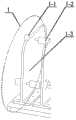
图1为本发明实施例冗余机械臂省力驱动机构方案原理图。FIG. 1 is a schematic diagram of a redundant mechanical arm labor-saving drive mechanism solution according to an embodiment of the present invention.
图2为本发明实施例驱动模块结构图;Fig. 2 is a structural diagram of a drive module according to an embodiment of the present invention;
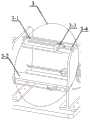
图3为本发明实施例转化模块结构图;Fig. 3 is the structural diagram of conversion module of the embodiment of the present invention;
图4为本发明实施例省力模块结构图;Fig. 4 is a structural diagram of a labor-saving module according to an embodiment of the present invention;
图5为本发明实施例关节模块结构图;Fig. 5 is a structural diagram of a joint module according to an embodiment of the present invention;
图6为本发明实施例关节结构图;Fig. 6 is a joint structural diagram of an embodiment of the present invention;
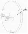
图7为本发明实施例关节座结构图;Fig. 7 is a structural diagram of the joint seat of the embodiment of the present invention;
图8为本发明实施例中心块结构图。Fig. 8 is a structural diagram of the central block of the embodiment of the present invention.
具体实施方式Detailed ways
下面结合实施例对本发明作进一步阐述。The present invention will be further elaborated below in conjunction with embodiment.
本发明提供了一种用于冗余机械臂关节的省力驱动机构,其特征在于包括臂杆、N根驱动绳索、关节模块固定板、省力模块、驱动模块、转化模块,N大于等于3;The invention provides a labor-saving drive mechanism for redundant mechanical arm joints, which is characterized in that it includes an arm rod, N driving ropes, a joint module fixing plate, a labor-saving module, a drive module, and a conversion module, and N is greater than or equal to 3;
冗余机械臂关节包括两个关节座,分别记为第一关节座、第二关节座,其中第一关节座固定在关节模块固定板上,N根驱动绳索分布在冗余机械臂关节周围,每根驱动绳索一端穿过冗余机械臂关节的第一关节座,固定在第二关节座上,另一端由省力模块牵引;The joints of the redundant manipulator include two joint seats, which are respectively denoted as the first joint seat and the second joint seat. The first joint seat is fixed on the joint module fixing plate, and N driving ropes are distributed around the joints of the redundant manipulator. One end of each driving rope passes through the first joint seat of the redundant mechanical arm joint, is fixed on the second joint seat, and the other end is pulled by the labor-saving module;
驱动模块用于产生N路旋转动力,转化模块用于将N路旋转动力转换为N路直线动力;省力模块采用N路直线动力分别驱动滑轮,由滑轮带动驱动绳索移动,从而实现所需直线动力为驱动绳索拉力的一半。上述用于冗余机械臂关节的省力驱动机构,还包括固定底板5,关节模块固定板垂直安装于固定底板5上。The drive module is used to generate N-way rotational power, and the conversion module is used to convert N-way rotational power into N-way linear power; the labor-saving module uses N-way linear power to drive the pulleys respectively, and the pulleys drive the rope to move, so as to achieve the required linear power half of the tension of the driving rope. The aforementioned labor-saving driving mechanism for redundant mechanical arm joints also includes a fixed bottom plate 5 on which the joint module fixed plate is vertically installed.
优选地,所述驱动模块1,包括N个驱动子模块和驱动电机固定装置1-3,每个驱动子模块包括驱动电机1-1、联轴器1-2;Preferably, the drive module 1 includes N drive sub-modules and a drive motor fixing device 1-3, each drive sub-module includes a drive motor 1-1 and a shaft coupling 1-2;
其中驱动电机固定装置1-3通过螺栓联接的方式垂直固定安装在固定底板5上,驱动电机1-1壳体通过螺栓联接的方式与固定底板5连接,联轴器1-2的一端连接到驱动电机转轴1-1上,联轴器1-2的另一端即为驱动模块1输出端,用于输出旋转动力。Wherein the drive motor fixing device 1-3 is vertically fixedly installed on the fixed base plate 5 by bolt connection, the drive motor 1-1 housing is connected with the fixed base plate 5 by bolt connection, and one end of the shaft coupling 1-2 is connected to On the rotating shaft 1-1 of the driving motor, the other end of the coupling 1-2 is the output end of the driving module 1 for outputting rotational power.
优选地,所述转化模块2包括丝杠左固定板、丝杠右固定板和N个转化子模块,每个转化子模块包括行星滚柱丝杠、螺母块、导轨;Preferably, the
丝杠左固定板通过螺栓联接的方式垂直固定到固定底板上,丝杠右固定板通过螺栓联接的方式固定到固定底板上,导轨两端分别与丝杠左固定板和丝杠右固定板固定连接,行星滚柱丝杠与导轨平行,行星滚柱丝杠的两端分别通过轴承与丝杠左固定板和丝杠右固定板连接,螺母块穿过行星滚柱丝杠、导轨,能够沿导轨移动,行星滚柱丝杠与驱动模块1输出端连接,行星滚柱丝杠旋转运动驱动螺母块沿直线运动。The left fixing plate of the lead screw is vertically fixed to the fixed base plate by means of bolt connection, the right fixing plate of the lead screw is fixed to the fixed base plate by means of bolt connection, and the two ends of the guide rail are respectively fixed to the left fixing plate of the lead screw and the right fixing plate of the lead screw Connection, the planetary roller screw is parallel to the guide rail, the two ends of the planetary roller screw are respectively connected to the left fixing plate of the screw and the right fixing plate of the screw through bearings, the nut block passes through the planetary roller screw and the guide rail, and can be moved along the The guide rail moves, the planetary roller screw is connected to the output end of the drive module 1, and the rotation of the planetary roller screw drives the nut block to move along a straight line.
优选地,所述省力模块包括N个省力子模块,每个省力子模块包括滑轮绳索、滑轨、滑轮、绳索连接块,其中滑轮绳索的一端与螺母块连接,绕过滑轮另一端固定到丝杠右固定板,滑轨两端通过螺栓联接的方式分别与丝杠右固定板和关节模块固定板连接,滑轨上开有滑槽,滑轮和绳索连接块通过销轴串联起来,销轴的一端处于滑槽内。Preferably, the labor-saving module includes N labor-saving sub-modules, and each labor-saving sub-module includes a pulley rope, a slide rail, a pulley, and a rope connection block, wherein one end of the pulley rope is connected to a nut block, and the other end of the pulley is fixed to the wire The right fixing plate of the bar and the two ends of the slide rail are respectively connected with the right fixing plate of the lead screw and the fixing plate of the joint module through bolt connection. There is a chute on the slide rail. One end is in the chute.
优选地,所述臂杆为“H”形结构,两侧为带有通孔的平板,中间为中空圆柱体,驱动绳索依次穿过关节模块固定板、臂杆两侧平板的通孔、第一关节座、再与第二关节座连接。Preferably, the arm is in an "H" shape, with flat plates with through holes on both sides and a hollow cylinder in the middle. The driving rope passes through the joint module fixing plate, the through holes of the plates on both sides of the arm, and the second The first joint base is connected with the second joint base.
优选地,N根驱动绳索均匀分布在冗余机械臂关节周围。Preferably, the N driving cables are evenly distributed around the redundant mechanical arm joints.
本发明减少了作用于冗余机械臂驱动机构的负载力,且基础技术较成熟,易实现。The invention reduces the load force acting on the driving mechanism of the redundant mechanical arm, and the basic technology is relatively mature and easy to realize.
实施例1:Example 1:
如图1所示,本发明某一具体实施例中,驱动机构主要由驱动模块1、转化模块2、省力模块3、关节模块4、固定底板5组成,驱动模块1提供动力,转化模块2将旋转运动转换为直线运动、省力模块3将转化模块2与关节模块4联接。As shown in Figure 1, in a specific embodiment of the present invention, the drive mechanism is mainly composed of a drive module 1, a
图2所示为驱动模块1,包括驱动电机固定装置1-3和N个驱动子模块,每个驱动子模块包括驱动电机1-1、联轴器1-2,其中,驱动电机固定装置1-3通过螺栓联接的方式固定到固定底板5上,驱动电机1-1的壳体通过螺栓联接的方式与固定底板5连接,联轴器1-2的一端连接到驱动电机1-1的转轴上,且驱动模块1中至少包含3个驱动电机1-1和3个联轴器1-2,3个驱动电机1-1和3个联轴器1-2都为120度圆周均匀分布。Fig. 2 shows drive module 1, comprises drive motor fixing device 1-3 and N drive submodules, and each drive submodule includes drive motor 1-1, shaft coupling 1-2, wherein, drive motor fixing device 1 -3 is fixed to the fixed base plate 5 by means of bolt connection, the housing of the driving motor 1-1 is connected to the fixed base plate 5 by means of bolt connection, and one end of the coupling 1-2 is connected to the rotating shaft of the drive motor 1-1 above, and the drive module 1 includes at least 3 drive motors 1-1 and 3 shaft couplings 1-2, and the 3 drive motors 1-1 and 3 shaft couplings 1-2 are evenly distributed in a 120-degree circle.
图3所示为转化模块2,转化模块2包括丝杠左固定板2-1、丝杠右固定板2-5和N个转化子模块,每个转化子模块包括行星滚柱丝杠2-2、螺母块2-3、导轨2-4,其中丝杠左固定板2-1通过螺栓联接的方式固定到固定底板5上,行星滚柱丝杠2-2的两端分别通过轴承与丝杠左固定板2-1和丝杠右固定板2-5连接,螺母块2-3中通过行星滚柱丝杠2-2、导轨2-4,并作为图4中滑轮绳索3-1的一固定端,丝杠右固定板2-5通过螺栓联接的方式固定到固定底板5上。且转化模块2中至少包含3个行星滚柱丝杠2-2、螺母块2-3和导轨2-4,3个行星滚柱丝杠2-2、螺母块2-3和导轨2-4都为120度圆周均匀分布。Figure 3 shows the
图4所示为省力模块3,省力模块3包括N个省力子模块,每个省力子模块包括滑轮绳索3-1、滑轨3-2、滑轮3-3、绳索连接块3-4,其中滑轮绳索3-1的一端与螺母块2-3连接,绕过滑轮3-3另一端固定到丝杠右固定板2-5,滑轨3-2两端通过螺栓联接的方式分别与丝杠右固定板2-5和关节模块固定板4-3连接,滑轨3-2上开有滑槽,滑轮3-3和绳索连接块3-4通过销轴串联起来,销轴的一端处于滑槽内。且省力模块3中至少包含3个滑轮绳索3-1、滑轨3-2、滑轮3-3和绳索连接块3-4,3个滑轮绳索3-1、滑轨3-2、滑轮3-3和绳索连接块3-4都为120度圆周均匀分布。Figure 4 shows the labor-saving
图5所示为关节模块4,包括臂杆4-1、驱动绳索4-2、关节模块固定板4-3、关节4-4。其中关节模块固定板4-3通过螺栓联接的方式固定到固定底板5上,臂杆4-1通过螺栓联接的方式固定到关节模块固定板4-3上,关节4-4与臂杆4-1通过螺栓联接,驱动绳索4-2一端与绳索连接块3-4连接,然后穿过关节模块固定板4-3、臂杆4-1、关节4-4上的绳孔,另一端固定到关节4-4的末端。且关节模块4中至少包含1个臂杆4-1、3根驱动绳索4-2、1个关节4-4,3根驱动绳索4-2为120度圆周均匀分布。Fig. 5 shows the
图6所示为关节4-4,包括关节座4-4-1、中心块4-4-2、铜套4-4-3,关节座4-4-1和中心块4-4-2分别如图7和图8所示。Figure 6 shows the joint 4-4, including the joint seat 4-4-1, the central block 4-4-2, the copper sleeve 4-4-3, the joint seat 4-4-1 and the central block 4-4-2 They are shown in Figure 7 and Figure 8 respectively.
关节4-4中的关节座4-4-1的数量为2,且两关节座正交分布,两关节座通过中心块4-4-2和铜套4-4-3连接,其中中心块4-4-2端面的1个轴对应关节座4-4-1的1个孔,孔与轴之间通过铜套4-4-3连接,实现轴的旋转运动。具体为:关节座4-4-1包括一个平板和两个垂直于平板一侧的支柱,支柱的端部为C型接口,中心块4-4-2为立方块,立方块的中间四个面,每个面中心向外突出一轴,相对的两个轴为一组,该组轴与关节座两个支柱上的C型接口配合连接,由两个支柱上的C型接口分别握住相对的两个轴,并且能够绕轴旋转。The number of joint seats 4-4-1 in the joint 4-4 is 2, and the two joint seats are distributed orthogonally, and the two joint seats are connected by the central block 4-4-2 and the copper sleeve 4-4-3, wherein the central block One shaft on the end face of 4-4-2 corresponds to one hole of the joint seat 4-4-1, and the hole and the shaft are connected by a copper sleeve 4-4-3 to realize the rotational movement of the shaft. Specifically: the joint seat 4-4-1 includes a flat plate and two pillars perpendicular to one side of the flat plate, the ends of the pillars are C-shaped joints, the central block 4-4-2 is a cube, and the middle four A shaft protrudes outward from the center of each face, and the opposite two shafts form a group. This group of shafts is connected with the C-shaped interface on the two pillars of the joint seat, and is held by the C-shaped interface on the two pillars. Opposite two axes, and can rotate around the axis.
工作原理如下:驱动电机1-1通过联轴器1-2带动行星滚柱丝杠2-2中的主丝杠旋转,主丝杠的旋转运动转化为螺母块2-3的直线运动,螺母块2-3的直线运动带动滑轮绳索3-1移动,使得滑轮3-3和绳索连接块3-4共同沿着滑轨3-2移动,进一步驱动驱动绳索4-2,三根驱动绳索4-2驱动关节4-4实现既定动作。在上述运动过程中,由于采用了省力模块3,使得滑轮绳索3-1受到的拉力理论上等于驱动绳索4-2中的一半拉力,最终作用到螺母块2-3上的倾斜力矩减少了一半,驱动行星滚柱丝杠2-2中主丝杠旋转所需要的力也减少了一半,达到了省力驱动的目的。The working principle is as follows: the drive motor 1-1 drives the main screw in the planetary roller screw 2-2 to rotate through the coupling 1-2, the rotational motion of the main screw is converted into the linear motion of the nut block 2-3, and the nut The linear motion of the block 2-3 drives the pulley rope 3-1 to move, so that the pulley 3-3 and the rope connection block 3-4 move together along the slide rail 3-2, further driving the driving rope 4-2, and the three driving ropes 4- 2 drives the joint 4-4 to realize the predetermined action. During the above movement, due to the use of the labor-saving
本发明虽然已以较佳实施例公开如上,但其并不是用来限定本发明,任何本领域技术人员在不脱离本发明的精神和范围内,都可以利用上述揭示的方法和技术内容对本发明技术方案做出可能的变动和修改,因此,凡是未脱离本发明技术方案的内容,依据本发明的技术实质对以上实施例所作的任何简单修改、等同变化及修饰,均属于本发明技术方案的保护范围。Although the present invention has been disclosed as above with preferred embodiments, it is not intended to limit the present invention, and any person skilled in the art can use the methods disclosed above and technical content to analyze the present invention without departing from the spirit and scope of the present invention. Possible changes and modifications are made in the technical solution. Therefore, any simple modification, equivalent change and modification made to the above embodiments according to the technical essence of the present invention, which do not depart from the content of the technical solution of the present invention, all belong to the technical solution of the present invention. protected range.
Claims (7)
Priority Applications (1)
| Application Number | Priority Date | Filing Date | Title |
|---|---|---|---|
| CN202211295679.2ACN115741655A (en) | 2022-10-21 | 2022-10-21 | Labor-saving driving mechanism for redundant mechanical arm joint |
Applications Claiming Priority (1)
| Application Number | Priority Date | Filing Date | Title |
|---|---|---|---|
| CN202211295679.2ACN115741655A (en) | 2022-10-21 | 2022-10-21 | Labor-saving driving mechanism for redundant mechanical arm joint |
Publications (1)
| Publication Number | Publication Date |
|---|---|
| CN115741655Atrue CN115741655A (en) | 2023-03-07 |
Family
ID=85352739
Family Applications (1)
| Application Number | Title | Priority Date | Filing Date |
|---|---|---|---|
| CN202211295679.2APendingCN115741655A (en) | 2022-10-21 | 2022-10-21 | Labor-saving driving mechanism for redundant mechanical arm joint |
Country Status (1)
| Country | Link |
|---|---|
| CN (1) | CN115741655A (en) |
Citations (7)
| Publication number | Priority date | Publication date | Assignee | Title |
|---|---|---|---|---|
| US3497083A (en)* | 1968-05-10 | 1970-02-24 | Us Navy | Tensor arm manipulator |
| CN101518490A (en)* | 2009-03-26 | 2009-09-02 | 上海大学 | Active partial body weight support treadmill training device and active partial body weight support treadmill training method |
| CN102744732A (en)* | 2012-06-20 | 2012-10-24 | 东莞东聚电子电讯制品有限公司 | A snake-like robotic arm |
| KR20130106970A (en)* | 2012-03-21 | 2013-10-01 | 주식회사 엔티리서치 | Human power amplification device using wire rope |
| CN104552286A (en)* | 2014-12-26 | 2015-04-29 | 上海大学 | Continuous multi-joint mechanical arm device |
| CN107363820A (en)* | 2017-06-21 | 2017-11-21 | 浙江大学 | The highly redundant flexible mechanical arm assembly of detectable joint posture |
| US20190186605A1 (en)* | 2015-10-28 | 2019-06-20 | Nsk Ltd. | Actuator |
- 2022
- 2022-10-21CNCN202211295679.2Apatent/CN115741655A/enactivePending
Patent Citations (7)
| Publication number | Priority date | Publication date | Assignee | Title |
|---|---|---|---|---|
| US3497083A (en)* | 1968-05-10 | 1970-02-24 | Us Navy | Tensor arm manipulator |
| CN101518490A (en)* | 2009-03-26 | 2009-09-02 | 上海大学 | Active partial body weight support treadmill training device and active partial body weight support treadmill training method |
| KR20130106970A (en)* | 2012-03-21 | 2013-10-01 | 주식회사 엔티리서치 | Human power amplification device using wire rope |
| CN102744732A (en)* | 2012-06-20 | 2012-10-24 | 东莞东聚电子电讯制品有限公司 | A snake-like robotic arm |
| CN104552286A (en)* | 2014-12-26 | 2015-04-29 | 上海大学 | Continuous multi-joint mechanical arm device |
| US20190186605A1 (en)* | 2015-10-28 | 2019-06-20 | Nsk Ltd. | Actuator |
| CN107363820A (en)* | 2017-06-21 | 2017-11-21 | 浙江大学 | The highly redundant flexible mechanical arm assembly of detectable joint posture |
Similar Documents
| Publication | Publication Date | Title |
|---|---|---|
| CN109955049B (en) | Vertical posture adjusting system for large-scale assembly | |
| CN105150193B (en) | A kind of super redundancy flexible mechanical arm based on closed loop line driving | |
| CN106903712B (en) | Two-degree-of-freedom collinear mechanical arm joint based on differential rope transmission | |
| CN101190527A (en) | Two degrees of freedom mobile parallel decoupling mechanism | |
| CN109352639B (en) | Underwater rope driving mechanical arm system carried by autonomous underwater vehicle | |
| CN109352627B (en) | Space three-dimensional mobile parallel manipulator | |
| CN109176491A (en) | A kind of single-degree-of-freedom module that rope drives and the multiple-degree-of-freedom mechanism using it | |
| CN107225559A (en) | A kind of four-degree-of-freedom high speed parallel robot of achievable SCARA motions | |
| CN103240737B (en) | Three-degree-of-freedom hybrid drive winding type flexible cable parallel mechanism | |
| CN104626113A (en) | Connecting rod and synchronous belt combined transmission four-degree-of-freedom robot | |
| CN106426111B (en) | The flat one turn of high-speed parallel manipulator of four branch of continuous rotary three | |
| CN109079756B (en) | Three-degree-of-freedom parallel mechanism applied to force feedback equipment | |
| CN104476567A (en) | Six-degree-of-freedom parallel mechanism with rope-driven linear joint | |
| CN110962153A (en) | An industrial palletizing mechanical gripper | |
| CN106976070A (en) | A kind of high speed shunting means of achievable three-dimensional translating and one-dimensional rotation | |
| CN116713978A (en) | Three-branch four-degree-of-freedom high-speed parallel robot with linkage sliding table connecting rod | |
| CN115741655A (en) | Labor-saving driving mechanism for redundant mechanical arm joint | |
| CN210790962U (en) | A six-degree-of-freedom vertical serial manipulator | |
| CN113733150B (en) | Lightweight collaborative robotic arm | |
| CN115946149B (en) | A rope-driven tensegrity jointed seven-degree-of-freedom humanoid robotic arm | |
| CN1701927A (en) | Flexible rope driven three and four degree of freedom decoupling parallel mechanism | |
| CN201519962U (en) | Three-dimensional translational degrees of freedom mixed-driven flexible cable parallel mechanism | |
| CN101497193B (en) | A laser processing robot mechanism | |
| CN114952908B (en) | Wire pulling out and gas-electricity hybrid power clamping mechanism based on gear rack | |
| CN110076444A (en) | A kind of two-freedom parallel connection head for Friction Stir Welding |
Legal Events
| Date | Code | Title | Description |
|---|---|---|---|
| PB01 | Publication | ||
| PB01 | Publication | ||
| SE01 | Entry into force of request for substantive examination | ||
| SE01 | Entry into force of request for substantive examination | ||
| RJ01 | Rejection of invention patent application after publication | Application publication date:20230307 | |
| RJ01 | Rejection of invention patent application after publication |