CN115738074A - Electrical stimulation device and electrical stimulation system - Google Patents
Electrical stimulation device and electrical stimulation systemDownload PDFInfo
- Publication number
- CN115738074A CN115738074ACN202111031703.7ACN202111031703ACN115738074ACN 115738074 ACN115738074 ACN 115738074ACN 202111031703 ACN202111031703 ACN 202111031703ACN 115738074 ACN115738074 ACN 115738074A
- Authority
- CN
- China
- Prior art keywords
- electrical stimulation
- signal
- frequency
- stimulation device
- circuit
- Prior art date
- Legal status (The legal status is an assumption and is not a legal conclusion. Google has not performed a legal analysis and makes no representation as to the accuracy of the status listed.)
- Pending
Links
- 230000000638stimulationEffects0.000titleclaimsabstractdescription186
- 238000012545processingMethods0.000claimsabstractdescription48
- 239000003990capacitorSubstances0.000claimsdescription33
- 235000014676Phragmites communisNutrition0.000claimsdescription8
- 230000004936stimulating effectEffects0.000abstract1
- 238000010586diagramMethods0.000description9
- 238000000034methodMethods0.000description7
- 230000005540biological transmissionEffects0.000description6
- 238000013461designMethods0.000description6
- 210000004556brainAnatomy0.000description4
- 210000005036nerveAnatomy0.000description4
- 230000001965increasing effectEffects0.000description3
- 206010020853Hypertonic bladderDiseases0.000description2
- 208000009722Overactive Urinary BladderDiseases0.000description2
- 208000003295carpal tunnel syndromeDiseases0.000description2
- 230000001939inductive effectEffects0.000description2
- 208000020629overactive bladderDiseases0.000description2
- 208000035824paresthesiaDiseases0.000description2
- 210000001428peripheral nervous systemAnatomy0.000description2
- 210000000278spinal cordAnatomy0.000description2
- 210000003594spinal gangliaAnatomy0.000description2
- 208000007101Muscle CrampDiseases0.000description1
- 230000003187abdominal effectEffects0.000description1
- 238000006243chemical reactionMethods0.000description1
- 238000011161developmentMethods0.000description1
- 201000010099diseaseDiseases0.000description1
- 208000037265diseases, disorders, signs and symptomsDiseases0.000description1
- 230000005674electromagnetic inductionEffects0.000description1
- 238000001914filtrationMethods0.000description1
- 238000002513implantationMethods0.000description1
- 238000004519manufacturing processMethods0.000description1
- 238000012986modificationMethods0.000description1
- 230000004048modificationEffects0.000description1
- 210000000578peripheral nerveAnatomy0.000description1
- 206010036596premature ejaculationDiseases0.000description1
- 206010038464renal hypertensionDiseases0.000description1
- 210000000273spinal nerve rootAnatomy0.000description1
- 230000001225therapeutic effectEffects0.000description1
- 210000002972tibial nerveAnatomy0.000description1
Images


Classifications
- A—HUMAN NECESSITIES
- A61—MEDICAL OR VETERINARY SCIENCE; HYGIENE
- A61N—ELECTROTHERAPY; MAGNETOTHERAPY; RADIATION THERAPY; ULTRASOUND THERAPY
- A61N1/00—Electrotherapy; Circuits therefor
- A61N1/18—Applying electric currents by contact electrodes
- A61N1/32—Applying electric currents by contact electrodes alternating or intermittent currents
- A61N1/36—Applying electric currents by contact electrodes alternating or intermittent currents for stimulation
- A61N1/3605—Implantable neurostimulators for stimulating central or peripheral nerve system
- A61N1/36125—Details of circuitry or electric components
- A—HUMAN NECESSITIES
- A61—MEDICAL OR VETERINARY SCIENCE; HYGIENE
- A61N—ELECTROTHERAPY; MAGNETOTHERAPY; RADIATION THERAPY; ULTRASOUND THERAPY
- A61N1/00—Electrotherapy; Circuits therefor
- A61N1/18—Applying electric currents by contact electrodes
- A61N1/32—Applying electric currents by contact electrodes alternating or intermittent currents
- A61N1/36—Applying electric currents by contact electrodes alternating or intermittent currents for stimulation
- A61N1/3605—Implantable neurostimulators for stimulating central or peripheral nerve system
- A61N1/36057—Implantable neurostimulators for stimulating central or peripheral nerve system adapted for stimulating afferent nerves
- A—HUMAN NECESSITIES
- A61—MEDICAL OR VETERINARY SCIENCE; HYGIENE
- A61N—ELECTROTHERAPY; MAGNETOTHERAPY; RADIATION THERAPY; ULTRASOUND THERAPY
- A61N1/00—Electrotherapy; Circuits therefor
- A61N1/18—Applying electric currents by contact electrodes
- A61N1/32—Applying electric currents by contact electrodes alternating or intermittent currents
- A61N1/36—Applying electric currents by contact electrodes alternating or intermittent currents for stimulation
- A61N1/3605—Implantable neurostimulators for stimulating central or peripheral nerve system
- A61N1/3606—Implantable neurostimulators for stimulating central or peripheral nerve system adapted for a particular treatment
- A—HUMAN NECESSITIES
- A61—MEDICAL OR VETERINARY SCIENCE; HYGIENE
- A61N—ELECTROTHERAPY; MAGNETOTHERAPY; RADIATION THERAPY; ULTRASOUND THERAPY
- A61N1/00—Electrotherapy; Circuits therefor
- A61N1/18—Applying electric currents by contact electrodes
- A61N1/32—Applying electric currents by contact electrodes alternating or intermittent currents
- A61N1/36—Applying electric currents by contact electrodes alternating or intermittent currents for stimulation
- A61N1/3605—Implantable neurostimulators for stimulating central or peripheral nerve system
- A61N1/36128—Control systems
- A61N1/36146—Control systems specified by the stimulation parameters
- A61N1/3615—Intensity
- A61N1/36153—Voltage
- A—HUMAN NECESSITIES
- A61—MEDICAL OR VETERINARY SCIENCE; HYGIENE
- A61N—ELECTROTHERAPY; MAGNETOTHERAPY; RADIATION THERAPY; ULTRASOUND THERAPY
- A61N1/00—Electrotherapy; Circuits therefor
- A61N1/18—Applying electric currents by contact electrodes
- A61N1/32—Applying electric currents by contact electrodes alternating or intermittent currents
- A61N1/36—Applying electric currents by contact electrodes alternating or intermittent currents for stimulation
- A61N1/3605—Implantable neurostimulators for stimulating central or peripheral nerve system
- A61N1/36128—Control systems
- A61N1/36146—Control systems specified by the stimulation parameters
- A61N1/3615—Intensity
- A61N1/36157—Current
- A—HUMAN NECESSITIES
- A61—MEDICAL OR VETERINARY SCIENCE; HYGIENE
- A61N—ELECTROTHERAPY; MAGNETOTHERAPY; RADIATION THERAPY; ULTRASOUND THERAPY
- A61N1/00—Electrotherapy; Circuits therefor
- A61N1/18—Applying electric currents by contact electrodes
- A61N1/32—Applying electric currents by contact electrodes alternating or intermittent currents
- A61N1/36—Applying electric currents by contact electrodes alternating or intermittent currents for stimulation
- A61N1/3605—Implantable neurostimulators for stimulating central or peripheral nerve system
- A61N1/36128—Control systems
- A61N1/36146—Control systems specified by the stimulation parameters
- A61N1/36167—Timing, e.g. stimulation onset
- A61N1/36171—Frequency
- A—HUMAN NECESSITIES
- A61—MEDICAL OR VETERINARY SCIENCE; HYGIENE
- A61N—ELECTROTHERAPY; MAGNETOTHERAPY; RADIATION THERAPY; ULTRASOUND THERAPY
- A61N1/00—Electrotherapy; Circuits therefor
- A61N1/18—Applying electric currents by contact electrodes
- A61N1/32—Applying electric currents by contact electrodes alternating or intermittent currents
- A61N1/36—Applying electric currents by contact electrodes alternating or intermittent currents for stimulation
- A61N1/372—Arrangements in connection with the implantation of stimulators
- A61N1/37211—Means for communicating with stimulators
- A61N1/37235—Aspects of the external programmer
- A—HUMAN NECESSITIES
- A61—MEDICAL OR VETERINARY SCIENCE; HYGIENE
- A61N—ELECTROTHERAPY; MAGNETOTHERAPY; RADIATION THERAPY; ULTRASOUND THERAPY
- A61N1/00—Electrotherapy; Circuits therefor
- A61N1/18—Applying electric currents by contact electrodes
- A61N1/32—Applying electric currents by contact electrodes alternating or intermittent currents
- A61N1/36—Applying electric currents by contact electrodes alternating or intermittent currents for stimulation
- A61N1/372—Arrangements in connection with the implantation of stimulators
- A61N1/378—Electrical supply
- A61N1/3787—Electrical supply from an external energy source
- A—HUMAN NECESSITIES
- A61—MEDICAL OR VETERINARY SCIENCE; HYGIENE
- A61N—ELECTROTHERAPY; MAGNETOTHERAPY; RADIATION THERAPY; ULTRASOUND THERAPY
- A61N1/00—Electrotherapy; Circuits therefor
- A61N1/02—Details
- A61N1/04—Electrodes
- A61N1/05—Electrodes for implantation or insertion into the body, e.g. heart electrode
- A61N1/0526—Head electrodes
- A61N1/0529—Electrodes for brain stimulation
- A—HUMAN NECESSITIES
- A61—MEDICAL OR VETERINARY SCIENCE; HYGIENE
- A61N—ELECTROTHERAPY; MAGNETOTHERAPY; RADIATION THERAPY; ULTRASOUND THERAPY
- A61N1/00—Electrotherapy; Circuits therefor
- A61N1/02—Details
- A61N1/04—Electrodes
- A61N1/05—Electrodes for implantation or insertion into the body, e.g. heart electrode
- A61N1/0551—Spinal or peripheral nerve electrodes
Landscapes
- Health & Medical Sciences (AREA)
- Radiology & Medical Imaging (AREA)
- Engineering & Computer Science (AREA)
- Biomedical Technology (AREA)
- Nuclear Medicine, Radiotherapy & Molecular Imaging (AREA)
- Life Sciences & Earth Sciences (AREA)
- Animal Behavior & Ethology (AREA)
- General Health & Medical Sciences (AREA)
- Public Health (AREA)
- Veterinary Medicine (AREA)
- Neurology (AREA)
- Neurosurgery (AREA)
- Electrotherapy Devices (AREA)
Abstract
Translated fromChinese
Description
Translated fromChinese技术领域technical field
本发明关于一种电刺激装置,特别是关于一种电刺激装置与电刺激系统。The present invention relates to an electric stimulation device, in particular to an electric stimulation device and an electric stimulation system.
背景技术Background technique
近年来,有数十种治疗性的神经电刺激装置被发展出来,并且每年至少有数万人接受电刺激装置的植入手术。由于精密制造技术的发展,医疗仪器的尺寸已微小化,并可植入人体的内部,例如,植入式电刺激装置。In recent years, dozens of therapeutic nerve electrical stimulation devices have been developed, and at least tens of thousands of people receive implantation of electrical stimulation devices every year. Due to the development of precision manufacturing technology, the size of medical instruments has been miniaturized and can be implanted inside the human body, for example, implantable electrical stimulation devices.
然而,在目前的植入式电刺激装置中,无电池的植入式电刺激器通过外部的控制器以无线供电的方式,将电能提供给植入式电刺激器进行电刺激,且外部控制器与无电池的植入式电刺激器需精准对位,否则植入式电刺激器无法接收到电能。另外,当植入式电刺激器植入的位置较深时,植入式电刺激器接收电能的效率会大幅降低。此外,植入式电刺激器容易被误感应,只要靠近相似电磁波的不特定发射源,植入式电刺激器即可受到感应进行电刺激,如此会增加使用者的困扰。因此,如何有效地改善植入式电刺激装置的设计,以降低电路设计的复杂度及减小电刺激装置的尺寸,并增加适用上的便利性成为一重要议题。However, in the current implantable electrical stimulation devices, the battery-free implantable electrical stimulator provides electric energy to the implantable electrical stimulator for electrical stimulation through an external controller in a wireless power supply mode, and the external control The implantable electrical stimulator and the battery-free implantable electrical stimulator must be accurately aligned, otherwise the implantable electrical stimulator cannot receive electrical energy. In addition, when the implantable electrical stimulator is implanted at a deeper position, the efficiency of receiving electrical energy by the implantable electrical stimulator will be greatly reduced. In addition, implantable electrical stimulators are prone to misinduction. As long as they are close to unspecified emission sources similar to electromagnetic waves, implantable electrical stimulators can be induced to perform electrical stimulation, which will increase the confusion of users. Therefore, how to effectively improve the design of the implantable electrical stimulation device to reduce the complexity of the circuit design, reduce the size of the electrical stimulation device, and increase the convenience of application has become an important issue.
发明内容Contents of the invention
本发明提供一种电刺激装置及电刺激系统,借以降低电路设计的复杂度及减小电刺激装置的尺寸,并增加适用上的便利性。The invention provides an electric stimulation device and an electric stimulation system, thereby reducing the complexity of circuit design and reducing the size of the electric stimulation device, and increasing the convenience in application.
本发明提供一种电刺激装置,包括信号接收电路与信号处理电路。信号接收电路接收并输出频率信号。信号处理电路接收整流信号,并依据频率信号,产生电刺激信号。The invention provides an electrical stimulation device, which includes a signal receiving circuit and a signal processing circuit. The signal receiving circuit receives and outputs the frequency signal. The signal processing circuit receives the rectified signal and generates an electric stimulation signal according to the frequency signal.
本发明提供一种电刺激系统,包括外部控制器与电刺激装置。外部控制器包括信号产生电路与信号发射电路。信号产生电路产生频率信号。信号发射电路接收并传送该频率信号。电刺激装置包括信号接收电路与信号处理电路。信号接收电路接收并输出频率信号。信号处理电路接收频率信号,并依据频率信号,产生电刺激信号。The invention provides an electrical stimulation system, which includes an external controller and an electrical stimulation device. The external controller includes a signal generating circuit and a signal transmitting circuit. The signal generating circuit generates a frequency signal. The signal transmitting circuit receives and transmits the frequency signal. The electrical stimulation device includes a signal receiving circuit and a signal processing circuit. The signal receiving circuit receives and outputs the frequency signal. The signal processing circuit receives the frequency signal and generates an electrical stimulation signal according to the frequency signal.
本发明所公开的电刺激装置及电刺激系统,通过信号接收电路接收并输出频率信号,信号处理电路接收频率信号,并依据频率信号,产生电刺激信号。如此一来,可以有效地降低电路设计的复杂度及减小电刺激装置的尺寸,并增加适用上的便利性。The electrical stimulation device and the electrical stimulation system disclosed in the present invention receive and output frequency signals through a signal receiving circuit, and the signal processing circuit receives the frequency signals and generates electrical stimulation signals according to the frequency signals. In this way, the complexity of circuit design and the size of the electrical stimulation device can be effectively reduced, and the convenience of application can be increased.
附图说明Description of drawings
图1为依据本发明的一实施例的电刺激系统的示意图。FIG. 1 is a schematic diagram of an electrical stimulation system according to an embodiment of the present invention.
图2为依据本发明的一实施例的电刺激装置的示意图。FIG. 2 is a schematic diagram of an electrical stimulation device according to an embodiment of the present invention.
图3为依据本发明的另一实施例的电刺激装置的示意图。FIG. 3 is a schematic diagram of an electrical stimulation device according to another embodiment of the present invention.
图4为依据本发明的一实施例的电刺激装置的电刺激信号波形图。FIG. 4 is a waveform diagram of electrical stimulation signals of an electrical stimulation device according to an embodiment of the present invention.
图5为依据本发明的另一实施例的电刺激系统的示意图。FIG. 5 is a schematic diagram of an electrical stimulation system according to another embodiment of the present invention.
图6为依据本发明的另一实施例的电刺激系统的示意图。FIG. 6 is a schematic diagram of an electrical stimulation system according to another embodiment of the present invention.
其中,附图标记说明如下:Wherein, the reference signs are explained as follows:
100,500,600:电刺激系统100, 500, 600: electrical stimulation system
110:外部控制器110: External controller
111:信号产生电路111: Signal generating circuit
112:信号发射电路112: Signal transmitting circuit
120,310,510,610:电刺激装置120, 310, 510, 610: Electrical stimulation devices
130:信号接收电路130: Signal receiving circuit
140,630:信号处理电路140, 630: Signal processing circuit
210:导线210: wire
211:一端211: one end
212:另一端212: the other end
221,222,321,322:电极221, 222, 321, 322: electrodes
620:整流电路620: rectifier circuit
520,650:保护电路520, 650: protection circuit
640:放大器640: Amplifier
C1,C2,C3,C4,C5:电容C1, C2, C3, C4, C5: capacitance
L1,L2,L3:电感L1, L2, L3: Inductance
R1,R2,R3:电阻R1, R2, R3: Resistors
Tp:脉冲周期时间Tp : Pulse cycle time
Td:持续时间Td : duration
Ts:电刺激信号周期时间Ts : electrical stimulation signal cycle time
具体实施方式Detailed ways
在以下所列举的各实施例中,将以相同的标号代表相同或相似的元件或组件。In the various embodiments listed below, the same or similar elements or components will be denoted by the same reference numerals.
图1为依据本发明的一实施例的电刺激系统的示意图。请参考图1,电刺激系统100包括外部控制器110与电刺激装置120。外部控制器110至少包括信号产生电路111与信号发射电路112。信号产生电路111用于产生频率信号。信号发射电路112耦接信号产生电路111,并用于传送频率信号。在一些实施例中,信号发射电路112可以包括线圈、天线、超音波电路或其组合,但本实施例不限于此。FIG. 1 is a schematic diagram of an electrical stimulation system according to an embodiment of the present invention. Please refer to FIG. 1 , the
在本实施例中,电刺激装置120可以是植入设备,且不具有电池。也就是说,电刺激装置120可以植入于人体的内部,并且外部控制器110可以设置于人体的外部。如此一来,本实施例的电刺激装置120不需要任何的控制单元,可以减少电路元件的使用,并降低电路设计的复杂度。在包括有控制单元的电刺激装置中,控制单元可用以执行将接收的能量进行变频、控制输出时间参数(例如脉冲宽度、脉冲速率)等。另外,外部控制器110可设置于电刺激装置120可接收到频率信号的位置,且外部控制器110不需要与电刺激装置120精准对位,可增加使用上的便利性。In this embodiment, the
电刺激装置120包括信号接收电路130与信号处理电路140。信号接收电路130接收并输出频率信号。在本实施例中,信号接收电路130可以包括线圈、天线、超音波电路或其组合,但本实施例不限于此。举例来说,信号接收电路130例如通过无线的方式接收信号发射电路112所传送的频率信号,并输出所接收的频率信号。在一些实施例中,信号发射电路112与信号接收电路130分别包括线圈时,信号发射电路112与信号接收电路130的传能方式可为电磁感应或电磁共振。在一些实施例中,信号发射电路112与信号接收电路130分别包括天线时,信号发射电路112与信号接收电路130的传能方式可为无线电波的形式。在一些实施例中,信号发射电路112包括超音波产生器,信号接收电路130包括超音波换能器(ultrasonic transducer)时,其传能方式可为超音波传能的形式。The
信号处理电路140耦接信号接收电路130。信号处理电路140接收频率信号,并依据频率信号,产生电刺激信号。举例来说,在一些实施例中,信号处理电路140可以对频率信号进行处理(例如滤波及/或匹配),以产生电刺激信号。接着,电刺激信号可以输出至导线210,使得导线210可以将电刺激信号传输至导线210的电极221或电极222对应的待刺激的目标区域,以便在该目标区域进行电刺激的操作,如图2所示。如图3所示,如图1中的信号接收电路130、与信号处理电路140皆可以封装的方式设置在电刺激装置310内,电极321及电极322设置在电刺激装置310的其中一面。在一些实施例中,信号处理电路140可以对频率信号进行处理(例如滤波及/或匹配),以产生电刺激信号,并将电刺激信号传输至电极321或电极322对应的待刺激的目标区域,以便在该目标区域进行电刺激的操作。在一些实施例中,电刺激装置120为扁状长方体,长度为3公分,宽度为1公分,高度为0.5公分。另外,图3的电刺激装置310可适用在人体组织较浅层处的神经,例如胫神经(tibial nerve)。The
进一步来说,信号处理电路140例如被动式滤波器。举例来说,信号处理电路140可以包括阻抗单元Z1、组抗单元Z2与组抗单元Z3。阻抗单元Z1具有第一端与第二端。阻抗单元Z1的第一端耦接信号接收电路130,以接收电刺激信号。组抗单元Z2具有第一端与第二端。阻抗单元Z2的第一端耦接阻抗单元Z1的第二端。阻抗单元Z2的第二端耦接接地端。组抗单元Z3具有第一端与第二端。阻抗单元Z3的第一端耦接阻抗单元Z1的第二端。阻抗单元Z3的第二端产生弦波电刺激信号。Furthermore, the
进一步来说,阻抗单元Z1可以包括电感L1与电容C1。电感L1具有第一端与第二端。电感L1的第一端作为阻抗单元Z1的第一端,并耦接信号接收电路130,以接收频率信号。电容C1具有第一端与第二端。电容C1的第一端耦接电感L1的第二端。电容C1的第二端作为阻抗单元Z1的第二端。Further, the impedance unit Z1 may include an inductor L1 and a capacitor C1. The inductor L1 has a first terminal and a second terminal. The first end of the inductor L1 serves as the first end of the impedance unit Z1 and is coupled to the
阻抗单元Z2可以包括电感L2与电容C2。电感L2具有第一端与第二端。电感L2的第一端作为阻抗单元Z2的第一端,并耦接电容C1的第二端。电感L2的第二端作为阻抗单元Z2的第二端,并耦接接地端。电容C2具有第一端与第二端。电容C2的第一端耦接电感L2的第一端。电容C2的第二端耦接电感L2的第二端。阻抗单元Z3可以包括电容C3与电感L3。电容C3具有第一端与第二端。电容C3的第一端作为阻抗单元Z3的第一端,并耦接电容C1的第二端。电感L3具有第一端与第二端。电感L3的第一端耦接电容C3的第二端。电感L3的第二端作为阻抗单元Z3的第二端,并产生电刺激信号。The impedance unit Z2 may include an inductor L2 and a capacitor C2. The inductor L2 has a first terminal and a second terminal. The first end of the inductor L2 serves as the first end of the impedance unit Z2 and is coupled to the second end of the capacitor C1. The second end of the inductor L2 serves as the second end of the impedance unit Z2 and is coupled to the ground. The capacitor C2 has a first terminal and a second terminal. A first end of the capacitor C2 is coupled to a first end of the inductor L2. The second end of the capacitor C2 is coupled to the second end of the inductor L2. The impedance unit Z3 may include a capacitor C3 and an inductor L3. The capacitor C3 has a first terminal and a second terminal. The first end of the capacitor C3 serves as the first end of the impedance unit Z3 and is coupled to the second end of the capacitor C1. The inductor L3 has a first terminal and a second terminal. A first end of the inductor L3 is coupled to a second end of the capacitor C3. The second end of the inductor L3 serves as the second end of the impedance unit Z3, and generates electrical stimulation signals.
在一些实施例中,上述电刺激信号的频率范围例如为100KHz至2000KHz的范围。进一步来说,电刺激信号的频率范围例如为200KHz至800KHz的范围。更进一步来说,电刺激信号的频率范围例如为480KHz至520KHz的范围。更进一步来说,电刺激信号的频率例如为500KHz。另外,上述电刺激信号例如为弦波信号。此外,在本实施例中,电刺激信号的频率与频率信号的频率可以相同。再者,本实施例的频率信号(即传能信号)与电刺激信号除了频率与波形相同外,频率信号与电刺激信号的振幅、脉冲频宽、脉冲重复频率也会相同,但本发明实施例不限于此。In some embodiments, the frequency range of the electrical stimulation signal is, for example, in the range of 100KHz to 2000KHz. Further, the frequency range of the electrical stimulation signal is, for example, in the range of 200KHz to 800KHz. Furthermore, the frequency range of the electrical stimulation signal is, for example, in the range of 480KHz to 520KHz. Furthermore, the frequency of the electrical stimulation signal is, for example, 500KHz. In addition, the electrical stimulation signal is, for example, a sinusoidal signal. In addition, in this embodiment, the frequency of the electrical stimulation signal and the frequency signal may be the same. Furthermore, the frequency signal (that is, the energy transmission signal) and the electrical stimulation signal in this embodiment are not only the same in frequency and waveform, but also the amplitude, pulse width, and pulse repetition frequency of the frequency signal and the electrical stimulation signal will be the same, but the implementation of the present invention Examples are not limited to this.
在一些实施例中,如图4所示,上述电刺激信号可以是脉冲射频(pulsedradio-frequency,PRF)信号,例如连续正弦波、连续三角波、或高频脉冲等,但本发明实施例不限于此。另外,当电刺激信号为脉冲交流信号时,一个脉冲周期时间(pulse cycle time)Tp包括多个脉冲信号以及至少一段休息的时间,而一个脉冲周期时间Tp为脉冲重复频率(pulserepetition frequency)的倒数。脉冲重复频率范围(也可简称为脉冲频率范围)例如介于0~1KHz,优选介于1~100Hz,而本实施例的电刺激信号的脉冲重复频率例如为2Hz。另外,一个脉冲周期时间中多个脉冲的持续时间(duration time)Td例如介于1~250毫秒(ms),优选介于为10~100ms,而本实施例的持续时间Td以25ms为例说明。在本实施例中,电刺激信号的频率为500KHz,换言之,电刺激信号周期时间Ts为约2微秒(μs)。此外,上述电刺激信号的频率即为图4的每条脉冲交流信号里的脉冲内频率(intra-pulse frequency)。再者,上述电刺激信号的电压范围可介于-25V~25V。进一步来说,上述电刺激信号的电压更可介于-20V~20V。上述电刺激信号的电流范围可介于0~60mA。进一步来说,上述电刺激信号的电流范围更可介于0~50mA。In some embodiments, as shown in FIG. 4, the above-mentioned electrical stimulation signal may be a pulsed radio-frequency (PRF) signal, such as a continuous sine wave, a continuous triangle wave, or a high-frequency pulse, etc., but embodiments of the present invention are not limited to this. In addition, when the electrical stimulation signal is a pulsed AC signal, a pulse cycle time (pulse cycle time) Tp includes multiple pulse signals and at least a period of rest, and a pulse cycle timeTp is the pulse repetition frequency (pulse cycle time) reciprocal. The pulse repetition frequency range (also referred to simply as the pulse frequency range) is, for example, 0-1 KHz, preferably 1-100 Hz, and the pulse repetition frequency of the electrical stimulation signal in this embodiment is, for example, 2 Hz. In addition, the duration (duration time) Td of multiple pulses in one pulse cycle time is for example between 1 ~ 250 milliseconds (ms), preferably between 10 ~ 100 ms, and the duration Td of this embodiment is 25 ms. Example. In this embodiment, the frequency of the electrical stimulation signal is 500 KHz, in other words, the cycle time Ts of the electrical stimulation signal is about 2 microseconds (μs). In addition, the frequency of the above electrical stimulation signal is the intra-pulse frequency (intra-pulse frequency) in each pulsed AC signal in FIG. 4 . Furthermore, the voltage range of the electrical stimulation signal can be between -25V˜25V. Furthermore, the voltage of the electrical stimulation signal can be between -20V˜20V. The current range of the electrical stimulation signal can be between 0-60mA. Furthermore, the current range of the electrical stimulation signal can be between 0-50mA.
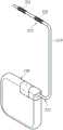
进一步来说,本实施例的外部控制器110可设置于人体的外部,且电刺激装置120可植入人体的内部。当电刺激装置120植入人体的体内时,电刺激装置120可放置在人体的皮下,且导线210的一端211与电刺激装置120连接,导线210的另一端212放置于接近待刺激的目标区域。以电刺激系统100为脊髓电刺激系统为例,至少部分导线210的该另一端212设置于硬膜外腔(epidural space)中,以就近电刺激脊髓、脊髓神经(spinal nerve)或是背根神经节(dorsal root ganglia,DRG)。电刺激装置120的信号处理电路140将电刺激信号传送至输出电极。也就是说,信号处理电路140可以通过导线210的一端211将电刺激信号传送至导线210的该另一端212上的输出电极(例如电极221或电极222),以电刺激目标区域。电刺激装置120传送出的电流会由导线210的一输出电极(例如电极221或电极222)流出,经由人体组织传导后再由另一电极流回(例如电极222或电极221)导线210。在本实施例中,电极221与电极222可以是一对电极。在一些实施例中,电极221可以为正极,且电极222可以为负极。在一些实施例中,电极221可以为负极,且电极222可以为正极。Furthermore, the
另外,电刺激的目标神经区域也可以是在脑部,以进行脑部皮质的电刺激或是深脑刺激(deep brain stimulation,DBS)或是腹部、周边神经。在一些实施例中,电刺激系统100也可用于缓解或治疗疼痛、膀胱过动症(overactive bladder,OAB)、肾性高血压、痉挛、早泄或腕隧道症候群(carpal tunnel syndrome,CTS)等疾病。在一些实施例中,电刺激的目标神经区域也可为侧隐窝(lateral recess)或周边神经系统(peripheral nervoussystem,PNS)。此外,对于电刺激的目标区域也可于单位时间中接受到较小的能量,进而确保是次阈值(subthreshold)的刺激,进而使植入电刺激系统的患者可以降低感受到不适感(paresthesia)的机会,以进行无不适感的治疗(paresthesia-free treatment)。In addition, the target nerve area of electrical stimulation can also be in the brain, so as to perform electrical stimulation of the brain cortex or deep brain stimulation (deep brain stimulation, DBS) or abdominal and peripheral nerves. In some embodiments, the
图5为依据本发明的另一实施例的电刺激系统的示意图。请参考图5,电刺激系统500包括外部控制器110与电刺激装置510。在本实施例中,外部控制器110与图1的外部控制器110相同或相似,可参考图1的实施例的说明,故在此不再赘述。FIG. 5 is a schematic diagram of an electrical stimulation system according to another embodiment of the present invention. Please refer to FIG. 5 , the
电刺激装置510包括信号接收电路130、信号处理电路140与保护电路520。在本实施例中,信号接收电路130、信号处理电路140与图1的信号接收电路130、信号处理电路140相同或相似,可参考图1的实施例,故在此不再赘述。The
保护电路520耦接信号处理电路140(例如阻抗单元Z3的第二端),且保护电路520用于决定是否输出信号处理电路140(例如阻抗单元Z3的第二端)所产生的电刺激信号。在一些实施例中,保护电路520例如为霍尔(Hall)开关或磁簧开关,但本发明实施例不限于此。举例来说,当外部控制器110设置有触发元件(例如磁铁)时,保护电路520(例如霍尔开关或磁簧开关)会感应到触发元件(例如磁铁)所产生的磁场而导通,以便输出电刺激信号。另外,当外部控制器110未设置有触发元件(例如磁铁)时,保护电路520(例如霍尔开关或磁簧开关)不会感应到触发元件而不导通,则保护电路520不会输出电刺激信号。如此一来,可以有效地避免电刺激装置510感应或接收到其他装置或发射源所产生的频率信号而有误动作(即直接进行电刺激操作)的情况发生,以增加电刺激装置510的安全性及减少使用者的困扰。The
另外,信号接收电路130、信号处理电路140保护电路520也可以封装的方式设置在如图3的电刺激装置310内,且信号处理电路140所产生的信号电路可以通过保护电路520传输至电极321或电极322对应的待刺激的目标区域,以便在该目标区域进行电刺激的操作。In addition, the
图6为依据本发明的另一实施例的电刺激系统的示意图。请参考图6,电刺激系统600包括外部控制器110与电刺激装置610。在本实施例中,外部控制器110与图1的外部控制器110相同或相似,可参考图1的实施例的说明,故在此不再赘述。FIG. 6 is a schematic diagram of an electrical stimulation system according to another embodiment of the present invention. Please refer to FIG. 6 , the
电刺激装置610包括信号接收电路130、整流电路620与信号处理电路630。在本实施例中,信号接收电路130与图1的信号接收电路130相同或相似,可参考图1的实施例,故在此不再赘述。The
整流电路620耦接信号接收电路130,接收频率信号,并对频率信号进行整流,以产生整流后的频率信号。在本实施例中,整流电路620可以是桥式整流器,例如半桥整流器或全桥整流器,但本发明实施例不限于此。另外,上述整流后的频率信号例如为方波信号。并且,此具有方波信号的整流后的频率信号可以通过信号处理电路630处理,以产生具有弦波信号的电刺激信号。在上述实施例中,电刺激信号是以方波信号为例,但本发明实施例不限于此。在一些实施例中,电刺激信号亦可为三角波、脉冲波等。The
信号处理电路630耦接整流电路620。亦即,整流电路620耦接于信号接收电路130与信号处理电路630之间。信号处理电路630接收频率信号(即整流后的频率信号),并依据频率信号,产生电刺激信号。举例来说,在一些实施例中,信号处理电路630与信号处理电路140类似,可以对频率信号进行处理(例如滤波及/或匹配),以产生电刺激信号。接着,电刺激信号可以输出至导线210,使得导线210可以将电刺激信号传输至导线210的电极221或电极222对应的待刺激的目标区域,以便在该目标区域进行电刺激的操作,如图2所示。在一些实施例中,如图3所示,如图6中的信号接收电路130、整流电路620、信号处理电路630与保护电路640皆可以封装的方式设置在电刺激装置310内,且信号处理电路630可以对频率信号进行处理(例如滤波及/或匹配),以产生电刺激信号,并通过保护电路640将电刺激信号传输至电极321或电极322对应的待刺激的目标区域,以便在该目标区域进行电刺激的操作。The
进一步来说,信号处理电路630可以是主动式滤波器。举例来说,信号处理电路630可以包括电阻R1、电阻R2、电容C4、电容C5、电阻R3与放大器640。Further, the
电阻R1具有第一端与第二端。电阻R1的第一端耦接整流电路620,以接收整流后的频率信号。电阻R2具有第一端与第二端。电阻R2的第一端耦接电阻R1的第二端。电阻R2的第二端耦接接地端。The resistor R1 has a first terminal and a second terminal. A first end of the resistor R1 is coupled to the
电容C4具有第一端与第二端。电容C4的第一端耦接电阻R1的第二端。电容C5具有第一端与第二端。电容C5的第一端耦接电容C4的第一端。电阻R3具有第一端与第二端。电阻R3的第一端耦接电容C4的第二端。电阻R3的第二端耦接电容C5的第二端。The capacitor C4 has a first terminal and a second terminal. A first terminal of the capacitor C4 is coupled to a second terminal of the resistor R1. The capacitor C5 has a first terminal and a second terminal. The first end of the capacitor C5 is coupled to the first end of the capacitor C4. The resistor R3 has a first terminal and a second terminal. A first terminal of the resistor R3 is coupled to a second terminal of the capacitor C4. The second end of the resistor R3 is coupled to the second end of the capacitor C5.
放大器640具有第一输入端、第二输入端与输出端。放大器640的第一输入端(例如正输入端)耦接接地端。放大器640的第二输入端(例如负输入端)耦接电阻R3的第二端。放大器640的输出端耦接电阻R3的第一端,并输出电刺激信号。The
在一些实施例中,上述电刺激信号的频率范围例如为100KHz至2000KHz的范围。进一步来说,电刺激信号的频率范围例如为200KHz至800KHz的范围。更进一步来说,电刺激信号的频率范围例如为480KHz至520KHz的范围。另外,上述电刺激信号例如为弦波信号。此外,在本实施例中,电刺激信号的频率与频率信号的频率可以相同。在一些实施例中,电刺激信号的频率与频率信号的频率必须相同。再者,本实施例的频率信号(即传能信号)与电刺激信号除了频率与波形相同外,频率信号与电刺激信号的振幅、脉冲频宽、脉冲重复频率也会相同,但本发明实施例不限于此。In some embodiments, the frequency range of the electrical stimulation signal is, for example, in the range of 100KHz to 2000KHz. Further, the frequency range of the electrical stimulation signal is, for example, in the range of 200KHz to 800KHz. Furthermore, the frequency range of the electrical stimulation signal is, for example, in the range of 480KHz to 520KHz. In addition, the electrical stimulation signal is, for example, a sinusoidal signal. In addition, in this embodiment, the frequency of the electrical stimulation signal and the frequency signal may be the same. In some embodiments, the frequency of the electrical stimulation signal and the frequency signal must be the same. Furthermore, the frequency signal (that is, the energy transmission signal) and the electrical stimulation signal in this embodiment are not only the same in frequency and waveform, but also the amplitude, pulse width, and pulse repetition frequency of the frequency signal and the electrical stimulation signal will be the same, but the implementation of the present invention Examples are not limited to this.
在本实施例中,电刺激装置610还包括保护电路650。保护电路650耦接信号处理电路630(例如放大器的输出端),且保护电路650用于决定是否输出信号处理电路630(例如放大器640的输出端)所产生的电刺激信号。在一些实施例中,保护电路650例如为霍尔开关或磁簧开关,但本发明实施例不限于此。举例来说,当外部控制器110设置有触发元件(例如磁铁)时,保护电路650(例如霍尔开关或磁簧开关)会感应到触发元件(例如磁铁)所产生的磁场而导通,以便输出电刺激信号。另外,当外部控制器110未设置有触发元件(例如磁铁)时,保护电路650(例如霍尔开关或磁簧开关)不会感应而不导通,则保护电路650不会输出电刺激信号。如此一来,可以有效地避免电刺激装置610感应或接收到其他装置或发射源所产生的频率信号而有误动作(即直接进行电刺激操作)的情况发生,以增加电刺激装置610的安全性及减少使用者的困扰。In this embodiment, the
综上所述,本发明所公开的电刺激装置与电刺激系统,通过信号接收电路接收并输出频率信号,信号处理电路接收频率信号,并依据频率信号,产生电刺激信号。如此一来,可以有效地降低电路设计的复杂度及减小电刺激装置的尺寸,并增加适用上的便利性。In summary, the electrical stimulation device and the electrical stimulation system disclosed in the present invention receive and output frequency signals through the signal receiving circuit, and the signal processing circuit receives the frequency signals and generates electrical stimulation signals according to the frequency signals. In this way, the complexity of circuit design and the size of the electrical stimulation device can be effectively reduced, and the convenience of application can be increased.
另外,本发明实施例的电刺激装置还包括保护电路,且保护电路可以耦接信号处理装置,以用于决定是否输出信号处理装置所产生的电刺激信号,其中电刺激信号为弦波信号。如此一来,可以有效地避免电刺激装置感应或接收到其他装置或发射源所产生的频率信号而有误动作(即直接进行电刺激操作)的情况发生,以增加电刺激装置的安全性及减少使用者的困扰。In addition, the electrical stimulation device in the embodiment of the present invention further includes a protection circuit, and the protection circuit can be coupled to the signal processing device for determining whether to output the electrical stimulation signal generated by the signal processing device, wherein the electrical stimulation signal is a sinusoidal signal. In this way, it is possible to effectively prevent the electrical stimulation device from sensing or receiving frequency signals generated by other devices or sources and cause false actions (that is, directly perform electrical stimulation operations), so as to increase the safety and security of the electrical stimulation device. Reduce user annoyance.
本发明虽以实施例公开如上,然其并非用以限定本发明的范围,任何所属技术领域中具有通常知识者,在不脱离本发明的精神和范围内,当可做些许的更动与润饰,因此本发明的保护范围当视后附的权利要求所界定者为准。Although the present invention is disclosed above with the embodiments, it is not intended to limit the scope of the present invention. Anyone with ordinary knowledge in the technical field may make some changes and modifications without departing from the spirit and scope of the present invention. , so the protection scope of the present invention shall prevail as defined by the appended claims.
Claims (24)
Translated fromChinesePriority Applications (4)
| Application Number | Priority Date | Filing Date | Title |
|---|---|---|---|
| CN202111031703.7ACN115738074A (en) | 2021-09-03 | 2021-09-03 | Electrical stimulation device and electrical stimulation system |
| US17/687,186US20230074017A1 (en) | 2021-09-03 | 2022-03-04 | Electrical stimulation device and electrical stimulation system |
| TW111130684ATW202310796A (en) | 2021-09-03 | 2022-08-16 | Electrical stimulation device and electrical stimulation system |
| EP22193177.7AEP4144410A1 (en) | 2021-09-03 | 2022-08-31 | Electrical stimulation device and electrical stimulation system |
Applications Claiming Priority (1)
| Application Number | Priority Date | Filing Date | Title |
|---|---|---|---|
| CN202111031703.7ACN115738074A (en) | 2021-09-03 | 2021-09-03 | Electrical stimulation device and electrical stimulation system |
Publications (1)
| Publication Number | Publication Date |
|---|---|
| CN115738074Atrue CN115738074A (en) | 2023-03-07 |
Family
ID=83151587
Family Applications (1)
| Application Number | Title | Priority Date | Filing Date |
|---|---|---|---|
| CN202111031703.7APendingCN115738074A (en) | 2021-09-03 | 2021-09-03 | Electrical stimulation device and electrical stimulation system |
Country Status (4)
| Country | Link |
|---|---|
| US (1) | US20230074017A1 (en) |
| EP (1) | EP4144410A1 (en) |
| CN (1) | CN115738074A (en) |
| TW (1) | TW202310796A (en) |
Families Citing this family (5)
| Publication number | Priority date | Publication date | Assignee | Title |
|---|---|---|---|---|
| US11925805B2 (en) | 2017-01-18 | 2024-03-12 | Soin Neuroscience, LLC | Tunable electrical noise signal technologies |
| US10828491B2 (en) | 2018-12-07 | 2020-11-10 | Avent, Inc. | Device and method to selectively and reversibly modulate a nervous system structure to inhibit pain |
| US11793443B2 (en) | 2022-02-01 | 2023-10-24 | Soin Neuroscience, LLC | Adjustable random electrical stimulation technologies |
| US12279871B2 (en)* | 2022-11-09 | 2025-04-22 | Soin Neuroscience, LLC | Electrode array for spatially random electrical stimulation |
| US11964155B1 (en) | 2023-07-14 | 2024-04-23 | Soin Neuroscience, LLC | Rapid frequency cycling during electrical stimulation |
Family Cites Families (8)
| Publication number | Priority date | Publication date | Assignee | Title |
|---|---|---|---|---|
| US8457757B2 (en)* | 2007-11-26 | 2013-06-04 | Micro Transponder, Inc. | Implantable transponder systems and methods |
| WO2012013360A1 (en)* | 2010-07-30 | 2012-02-02 | Md Start Sa | Implantable electrode device, in particular for sensing an intracardiac electrogram |
| WO2014089392A1 (en)* | 2012-12-07 | 2014-06-12 | Medtronic, Inc. | Minimally invasive implantable neurostimulation system |
| US9643023B2 (en)* | 2014-01-29 | 2017-05-09 | GiMer Medical Co., Ltd. | Method for monitoring power supply to implantable medical device |
| US9522270B2 (en)* | 2014-07-10 | 2016-12-20 | Micron Devices, LLC | Circuit for an implantable device |
| US10765868B2 (en)* | 2015-10-23 | 2020-09-08 | Gimer Medical Co., Ltd | Electrical stimulation device |
| US11471681B2 (en)* | 2016-01-20 | 2022-10-18 | Setpoint Medical Corporation | Batteryless implantable microstimulators |
| WO2017214638A1 (en)* | 2016-06-10 | 2017-12-14 | Williams, Jack | System for wireless recording and stimulating of bioelectric events |
- 2021
- 2021-09-03CNCN202111031703.7Apatent/CN115738074A/enactivePending
- 2022
- 2022-03-04USUS17/687,186patent/US20230074017A1/ennot_activeAbandoned
- 2022-08-16TWTW111130684Apatent/TW202310796A/enunknown
- 2022-08-31EPEP22193177.7Apatent/EP4144410A1/ennot_activeWithdrawn
Also Published As
| Publication number | Publication date |
|---|---|
| TW202310796A (en) | 2023-03-16 |
| US20230074017A1 (en) | 2023-03-09 |
| EP4144410A1 (en) | 2023-03-08 |
Similar Documents
| Publication | Publication Date | Title |
|---|---|---|
| CN115738074A (en) | Electrical stimulation device and electrical stimulation system | |
| US11497907B2 (en) | Dipolar antenna system and related methods | |
| US9468763B2 (en) | Systems and methods for electrical stimulation of sphenopalatine ganglion and other branches of cranial nerves | |
| EP3402567B1 (en) | An implantable relay module | |
| CN104096313B (en) | A kind of implantable neural electrical stimulation equipment and system | |
| US6520903B1 (en) | Multiple mode photonic stimulation device | |
| US20100010565A1 (en) | Extended range wireless muscular and neural stimulation | |
| US11413471B2 (en) | Central nerve magnetic stimulation device and healthcare or medical instrument having same | |
| JP2021510575A (en) | Radio nerve stimulator with injectable material | |
| US20130023958A1 (en) | Devices and Methods for Visually Indicating the Alignment of a Transcutaneous Energy Transfer Device Over an Implanted Medical Device | |
| US10022566B2 (en) | Apparatus, systems, and methods for current monitoring in ultrasound powered neurostimulation | |
| US20140114373A1 (en) | Intermediate Coupler to Facilitate Charging in an Implantable Medical Device System | |
| CN106924878A (en) | The implantable medical device of magnetic field and electric field charging can be used | |
| CN114377296B (en) | Non-invasive deep brain electromagnetic coupling neuromodulation device | |
| US20190054305A1 (en) | Charging-induced implant operation | |
| EP1320404A1 (en) | Acupuncture points stimulation for treating various diseases | |
| US20160158562A1 (en) | Systems and methods for neurostimulation of a peripheral nerve | |
| CN109420252B (en) | Electrical stimulation apparatus, method of generating electrical signal, and computer-readable storage medium | |
| TWI824667B (en) | Electrical stimulation device and electrical stimulation system | |
| CN105477785B (en) | Medical electronic device | |
| EP4144406A1 (en) | Closed loop control of tibial nerve stimulation and efficacy monitoring | |
| JPS6329663A (en) | Portable electric remedy apparatus | |
| JP2018511289A (en) | Spinal cord stimulation system | |
| US20250099763A1 (en) | Methods, Systems, Devices and Components for the Treatment of Stroke in a Patient with Interferential Cranial Electrical Stimulation | |
| NL2021497B1 (en) | An electrical stimulation device for body tissue |
Legal Events
| Date | Code | Title | Description |
|---|---|---|---|
| PB01 | Publication | ||
| PB01 | Publication | ||
| SE01 | Entry into force of request for substantive examination | ||
| SE01 | Entry into force of request for substantive examination |