CN115737125A - Endoscope transmission box and minimally invasive surgery robot - Google Patents
Endoscope transmission box and minimally invasive surgery robotDownload PDFInfo
- Publication number
- CN115737125A CN115737125ACN202211415657.5ACN202211415657ACN115737125ACN 115737125 ACN115737125 ACN 115737125ACN 202211415657 ACN202211415657 ACN 202211415657ACN 115737125 ACN115737125 ACN 115737125A
- Authority
- CN
- China
- Prior art keywords
- transmission
- endoscope
- groove
- wound
- helical direction
- Prior art date
- Legal status (The legal status is an assumption and is not a legal conclusion. Google has not performed a legal analysis and makes no representation as to the accuracy of the status listed.)
- Pending
Links
Images


Classifications
- A—HUMAN NECESSITIES
- A61—MEDICAL OR VETERINARY SCIENCE; HYGIENE
- A61B—DIAGNOSIS; SURGERY; IDENTIFICATION
- A61B34/00—Computer-aided surgery; Manipulators or robots specially adapted for use in surgery
- A61B34/30—Surgical robots
- A—HUMAN NECESSITIES
- A61—MEDICAL OR VETERINARY SCIENCE; HYGIENE
- A61B—DIAGNOSIS; SURGERY; IDENTIFICATION
- A61B34/00—Computer-aided surgery; Manipulators or robots specially adapted for use in surgery
- A61B34/30—Surgical robots
- A61B2034/305—Details of wrist mechanisms at distal ends of robotic arms
Landscapes
- Health & Medical Sciences (AREA)
- Surgery (AREA)
- Engineering & Computer Science (AREA)
- Life Sciences & Earth Sciences (AREA)
- Biomedical Technology (AREA)
- Robotics (AREA)
- Nuclear Medicine, Radiotherapy & Molecular Imaging (AREA)
- Heart & Thoracic Surgery (AREA)
- Medical Informatics (AREA)
- Molecular Biology (AREA)
- Animal Behavior & Ethology (AREA)
- General Health & Medical Sciences (AREA)
- Public Health (AREA)
- Veterinary Medicine (AREA)
- Endoscopes (AREA)
Abstract
Translated fromChinese
Description
Translated fromChinese本申请是于2021年8月4日提交的名称为“内窥镜传动盒及微创手术机器人”的中国专利申请202110893558.7的分案申请。This application is a divisional application of the Chinese patent application 202110893558.7 entitled "Endoscope Transmission Box and Minimally Invasive Surgical Robot" filed on August 4, 2021.
技术领域technical field
本发明涉及医疗器械技术领域,具体而言,涉及一种内窥镜传动盒及微创手术机器人。The invention relates to the technical field of medical instruments, in particular to an endoscope transmission box and a minimally invasive surgical robot.
背景技术Background technique
目前,微创手术具有创伤小、恢复速度快、有利于提高手术质量等诸多优点。但传统内窥镜手术也有诸多弊端,例如操作不便捷、操作精度低,医生容易疲劳和颤抖;随着科学技术的发展,微创手术机器人大大增加手术操作灵活性和操作精度,能够缓解医生的疲劳。微创手术机器人一般由医生控制台、手术臂系统组成,其中手术臂系统一般由多个持械臂和一个持镜臂组成,持镜臂用于夹持内窥镜,持镜臂上安装有内窥镜传动盒。At present, minimally invasive surgery has many advantages such as small trauma, fast recovery, and is conducive to improving the quality of surgery. However, traditional endoscopic surgery also has many disadvantages, such as inconvenient operation, low operation accuracy, and doctors are prone to fatigue and trembling; with the development of science and technology, minimally invasive surgical robots greatly increase the flexibility and accuracy of surgical operations, which can relieve doctors. fatigue. A minimally invasive surgical robot is generally composed of a doctor's console and an operating arm system. The operating arm system is generally composed of multiple arms and a mirror arm. The mirror arm is used to clamp the endoscope. The mirror arm is equipped with Endoscope transmission box.
现有技术中内窥镜传动盒是通过齿轮结构传动,如公告号为CN109965827B,名称为“内窥镜动力锁紧与调节机构及内窥镜持镜系统”的中国发明专利,齿轮结构制造及精度要求高,往往存在不易装配及具有转动回差的问题。In the prior art, the transmission box of the endoscope is driven by a gear structure, as the announcement number is CN109965827B, the Chinese invention patent named "Endoscope Power Locking and Adjusting Mechanism and Endoscope Mirror Holding System", the gear structure manufacturing and High precision is required, and there are often problems of difficult assembly and rotational hysteresis.
发明内容Contents of the invention
本发明提供了一种内窥镜传动盒及微创手术机器人,以解决现有技术中的内窥镜传动盒不易装配及具有转动回差的问题。The invention provides an endoscope transmission box and a minimally invasive surgical robot to solve the problems that the endoscope transmission box in the prior art is difficult to assemble and has rotational hysteresis.
为了解决上述问题,根据本发明的一个方面,本发明提供了一种内窥镜传动盒,包括:底座;执行部,可转动地设置在底座的一侧,用于执行内窥镜的旋转动作;传动部,可转动地设置在底座的另一侧,传动部上缠绕有第一拉绳和第二拉绳,第一拉绳和第二拉绳也分别缠绕在执行部上,以便传动部将驱动力传递给执行部;夹持结构,夹持结构包括可拆卸连接的第一夹持部和第二夹持部,第一夹持部和执行部连接,第一夹持部和第二夹持部之间形成用于安装内窥镜的容纳腔;第一夹持部包括第一主体和间隔设置在第一主体上的上限位槽、下限位槽;第二夹持部包括第二主体和间隔设置在第二主体上的上限位件、下限位件,上限位件卡入上限位槽内,下限位件卡入下限位槽内,第一主体和第二主体围绕形成容纳腔。In order to solve the above problems, according to one aspect of the present invention, the present invention provides an endoscope transmission box, comprising: a base; The transmission part is rotatably arranged on the other side of the base, the transmission part is wound with a first stay cord and a second stay cord, and the first stay cord and the second stay cord are respectively wound on the execution part, so that the transmission part The driving force is transmitted to the execution part; the clamping structure, the clamping structure includes a first clamping part and a second clamping part detachably connected, the first clamping part is connected to the execution part, the first clamping part and the second clamping part An accommodating cavity for installing an endoscope is formed between the clamping parts; the first clamping part includes a first main body and an upper limit groove and a lower limit groove arranged on the first main body at intervals; the second clamping part includes a second The main body and the upper limiter and the lower limiter arranged on the second body at intervals, the upper limiter snaps into the upper limiter groove, the lower limiter snaps into the lower limiter groove, and the first body and the second body surround to form an accommodating cavity.
进一步地,第一拉绳的一端沿第一螺旋方向缠绕在传动部上,第一拉绳的另一端沿第二螺旋方向缠绕在执行部上,第一螺旋方向和第二螺旋方向相反;第二拉绳的一端沿第二螺旋方向缠绕在传动部上,第二拉绳的另一端沿第一螺旋方向缠绕在执行部上。Further, one end of the first pull cord is wound on the transmission part along the first helical direction, and the other end of the first pull cord is wound on the execution part along the second helical direction, and the first helical direction is opposite to the second helical direction; One end of the second pull cord is wound on the transmission part along the second helical direction, and the other end of the second pull cord is wound on the execution part along the first helical direction.
进一步地,传动部包括:传动轴,可正转及反转地设置在底座上;第一传动轮,设置在传动轴上,第一拉绳的一端沿第一螺旋方向缠绕在第一传动轮上;第二传动轮,设置在传动轴上,第二拉绳的一端沿第二螺旋方向缠绕在第二传动轮上。Further, the transmission part includes: a transmission shaft, which can be rotated forward and reversely, and is arranged on the base; a first transmission wheel, which is arranged on the transmission shaft, and one end of the first pull rope is wound around the first transmission wheel along the first helical direction. On: the second transmission wheel is arranged on the transmission shaft, and one end of the second pull rope is wound on the second transmission wheel along the second helical direction.
进一步地,第一传动轮包括:第一套体,套设在传动轴上;第一卡套,和第一套体固定连接,第一卡套可拆卸地固定在传动轴上。Further, the first transmission wheel includes: a first sleeve sleeved on the transmission shaft; a first ferrule fixedly connected to the first sleeve, and the first ferrule is detachably fixed on the transmission shaft.
进一步地,第二传动轮包括:第二套体,套设在传动轴上;第二卡套,和第二套体固定连接,第二卡套可拆卸地固定在传动轴上,其中,第一套体和第二套体位于第一卡套和第二卡套之间。Further, the second transmission wheel includes: a second sleeve, sleeved on the transmission shaft; a second ferrule, fixedly connected to the second sleeve, and the second ferrule is detachably fixed on the transmission shaft, wherein the first The first body and the second body are located between the first ferrule and the second ferrule.
进一步地,内窥镜传动盒还包括:限位件,限位件和执行部固定连接;止挡件,设置在底座上,限位件和止挡件止挡配合,以限定执行部的转动范围。Further, the endoscope transmission box also includes: a limiter, which is fixedly connected to the execution part; a stopper, which is arranged on the base, and the limiter and the stopper stop and cooperate to limit the rotation of the execution part scope.
进一步地,限位件包括限位环和间隔设置在限位环上的两个限位块,限位环和执行部固定连接,两个限位块分别和止挡件限位配合。Further, the limiting member includes a limiting ring and two limiting blocks arranged at intervals on the limiting ring, the limiting ring is fixedly connected to the execution part, and the two limiting blocks are limitedly fitted with the stopper respectively.
进一步地,上限位槽和下限位槽沿同一方向延伸,上限位件和下限位件沿同一方向延伸;上限位槽包括相互连通的第一上深槽和上浅槽,上限位件包括上限位条和设置在上限位条上的第一上凸块,其中,上限位条的至少一部分插入上浅槽内,第一上凸块插入第一上深槽内。Further, the upper limit groove and the lower limit groove extend in the same direction, and the upper limit member and the lower limit member extend in the same direction; the upper limit groove includes a first upper deep groove and an upper shallow groove communicated with each other, and the upper limit member includes an upper limit The bar and the first upper protrusion arranged on the upper limit bar, wherein at least a part of the upper limit bar is inserted into the upper shallow groove, and the first upper protrusion is inserted into the first upper deep groove.
进一步地,下限位槽包括相互连通的下深槽和下浅槽,下限位件包括下限位条和设置在下限位条上的下凸块,其中,下限位条的至少一部分插入下浅槽内,下凸块插入下深槽内。Further, the lower limit groove includes a lower deep groove and a lower shallow groove connected to each other, and the lower limit member includes a lower limit bar and a lower protrusion provided on the lower limit bar, wherein at least a part of the lower limit bar is inserted into the lower shallow groove , the lower protrusion is inserted into the lower deep groove.
进一步地,执行部包括依次连接的转轴、连接板和偏置板,转轴可转动地设置在底座上,偏置板避让转轴的轴线,转轴的轴线穿过容纳腔,偏置板远离连接板的一端和第一夹持部连接,夹持结构和连接板之间具有避让空间;容纳腔的上端具有上开口,容纳腔的下端具有下开口,在转轴的径向方向上,容纳腔的中部区域的尺寸大于上开口、下开口的尺寸。Further, the execution part includes a rotating shaft, a connecting plate and a biasing plate connected in sequence, the rotating shaft is rotatably arranged on the base, the biasing plate avoids the axis of the rotating shaft, the axis of the rotating shaft passes through the accommodating cavity, and the biasing plate is away from the center of the connecting plate. One end is connected to the first clamping part, and there is an avoidance space between the clamping structure and the connecting plate; the upper end of the accommodating cavity has an upper opening, and the lower end of the accommodating cavity has a lower opening; in the radial direction of the rotating shaft, the middle area of the accommodating cavity The size is greater than the size of the upper opening and the lower opening.
根据本发明的另一个方面,本发明提供了一种微创手术机器人,微创手术机器人包括上述的内窥镜传动盒。According to another aspect of the present invention, the present invention provides a minimally invasive surgical robot, which includes the above-mentioned endoscope transmission box.
应用本发明的技术方案,提供了一种内窥镜传动盒,包括:底座;传动部,可转动地设置在底座上;执行部,可转动地设置在底座上;第一拉绳,第一拉绳的一端沿第一螺旋方向缠绕在传动部上,第一拉绳的另一端沿第二螺旋方向缠绕在执行部上,第一螺旋方向和第二螺旋方向相反;第二拉绳,第二拉绳的一端沿第二螺旋方向缠绕在传动部上,第二拉绳的另一端沿第一螺旋方向缠绕在执行部上;夹持结构,夹持结构包括可拆卸连接的第一夹持部和第二夹持部,第一夹持部和执行部连接,第一夹持部和第二夹持部之间形成用于安装内窥镜的容纳腔。采用该方案,第一拉绳和第二拉绳以不同螺旋方向分别缠绕在传动部和执行部上,这样传动部在转动时能够实现执行部的正转或反转,此种方式代替了现有的齿轮结构,采用拉绳的方式不需要太高的精度就可完成装配,且安装起来比较简单,并且,在装配时将两个拉绳拉紧即可实现精确传动,从而可减小或避免转动回差。而且,本方案中采用可拆卸连接的第一夹持部和第二夹持部,能够便于内窥镜的安装和拆卸,进一步提高了内窥镜传动盒的装配便利性。Applying the technical solution of the present invention, an endoscope transmission box is provided, including: a base; a transmission part, which is rotatably arranged on the base; an execution part, which is rotatably arranged on the base; One end of the pull rope is wound on the transmission part along the first helical direction, and the other end of the first pull rope is wound on the execution part along the second helical direction, and the first helical direction is opposite to the second helical direction; the second pull rope, the second helical direction One end of the second pull cord is wound on the transmission part along the second helical direction, and the other end of the second pull cord is wound on the execution part along the first helical direction; the clamping structure includes a detachably connected first clamping The first clamping part is connected to the second clamping part, the first clamping part is connected to the execution part, and an accommodating cavity for installing the endoscope is formed between the first clamping part and the second clamping part. With this solution, the first pull cord and the second pull cord are respectively wound on the transmission part and the execution part in different helical directions, so that the forward rotation or reverse rotation of the execution part can be realized when the transmission part rotates. This method replaces the existing Some gear structures can be assembled without too high precision by using the pull rope, and the installation is relatively simple, and the precise transmission can be realized by tightening the two pull ropes during assembly, thus reducing or Avoid rotational backlash. Moreover, the detachable connection of the first clamping part and the second clamping part is adopted in this solution, which can facilitate the installation and disassembly of the endoscope, and further improves the convenience of assembly of the endoscope transmission box.
附图说明Description of drawings
构成本申请的一部分的说明书附图用来提供对本发明的进一步理解,本发明的示意性实施例及其说明用于解释本发明,并不构成对本发明的不当限定。在附图中:The accompanying drawings constituting a part of the present application are used to provide a further understanding of the present invention, and the schematic embodiments and descriptions of the present invention are used to explain the present invention, and do not constitute an improper limitation of the present invention. In the attached picture:
图1示出了本发明的实施例提供的内窥镜传动盒的剖视图;Fig. 1 shows the cross-sectional view of the endoscope transmission box provided by the embodiment of the present invention;
图2示出了图1中的内窥镜传动盒的爆炸图;Figure 2 shows an exploded view of the endoscope drive box in Figure 1;
图3示出了图2中的内窥镜传动盒中的部分结构的示意图;Fig. 3 shows a schematic diagram of part of the structure in the endoscope drive box in Fig. 2;
图4示出了图3中传动部的局部放大图;Fig. 4 shows a partial enlarged view of the transmission part in Fig. 3;
图5示出了图2中的执行部和第一夹持部的结构图;Fig. 5 shows a structural diagram of the execution part and the first clamping part in Fig. 2;
图6示出了图5中上限位槽的局部放大图;Fig. 6 shows a partial enlarged view of the upper limit slot in Fig. 5;
图7示出了图5中下限位槽的局部放大图;Fig. 7 shows a partial enlarged view of the lower limiting groove in Fig. 5;
图8示出了图2中的第二夹持部的结构图;Fig. 8 shows a structural view of the second clamping part in Fig. 2;
图9示出了图2中底座的结构图;Fig. 9 shows the structural diagram of the base in Fig. 2;
图10示出了图2中固定板的结构图;Fig. 10 shows the structural diagram of fixed plate among Fig. 2;
图11示出了图2中外壳的结构图。FIG. 11 shows a structural view of the housing in FIG. 2 .
其中,上述附图包括以下附图标记:Wherein, the above-mentioned accompanying drawings include the following reference signs:
10、底座;11、底板;12、下支柱;13、凸柱;20、传动部;21、传动轴;22、第一传动轮;221、第一套体;222、第一卡套;2221、第一半环形件;2222、第二半环形件;23、第二传动轮;231、第二套体;232、第二卡套;30、执行部;31、转轴;32、连接板;33、偏置板;41、第一拉绳;42、第二拉绳;50、夹持结构;51、第一夹持部;511、第一主体;512、上限位槽;5121、第一上深槽;5122、上浅槽;5123、第二上深槽;513、下限位槽;5131、下深槽;5132、下浅槽;52、第二夹持部;521、第二主体;522、上限位件;5221、上限位条;5222、第一上凸块;5223、悬臂梁;5224、第二上凸块;523、下限位件;5231、下限位条;5232、下凸块;53、容纳腔;60、限位件;61、限位环;62、限位块;70、止挡件;80、固定板;81、顶板;82、上支柱;91、外壳;92、压杆;93、弹性件;94、连接轴。10. Base; 11. Bottom plate; 12. Lower pillar; 13. Protruding column; 20. Transmission part; 21. Transmission shaft; 22. First transmission wheel; 221. First sleeve; 222. First ferrule; 2221 , the first half ring; 2222, the second half ring; 23, the second transmission wheel; 231, the second sleeve; 232, the second ferrule; 30, the executive part; 31, the rotating shaft; 32, the connecting plate; 33. Bias plate; 41. First drawstring; 42. Second drawstring; 50. Clamping structure; 51. First clamping part; 511. First main body; 512. Upper limit slot; 5121. First Upper deep groove; 5122, upper shallow groove; 5123, second upper deep groove; 513, lower limit groove; 5131, lower deep groove; 5132, lower shallow groove; 52, second clamping part; 521, second main body; 522, upper limit piece; 5221, upper limit bar; 5222, first upper bump; 5223, cantilever beam; 5224, second upper bump; 523, lower limit piece; 5231, lower limit bar; 5232, lower bump ; Compression bar; 93, elastic member; 94, connecting shaft.
具体实施方式Detailed ways
下面将结合本发明实施例中的附图,对本发明实施例中的技术方案进行清楚、完整地描述。显然,所描述的实施例仅仅是本发明一部分实施例,而不是全部的实施例。以下对至少一个示例性实施例的描述实际上仅仅是说明性的,决不作为对本发明及其应用或使用的任何限制。基于本发明中的实施例,本领域普通技术人员在没有作出创造性劳动前提下所获得的所有其他实施例,都属于本发明保护的范围。The following will clearly and completely describe the technical solutions in the embodiments of the present invention with reference to the drawings in the embodiments of the present invention. Apparently, the described embodiments are only some of the embodiments of the present invention, but not all of them. The following description of at least one exemplary embodiment is merely illustrative in nature and in no way taken as limiting the invention, its application or uses. Based on the embodiments of the present invention, all other embodiments obtained by persons of ordinary skill in the art without creative efforts fall within the protection scope of the present invention.
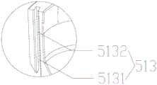
如图1至图11所示,本发明的实施例提供了一种内窥镜传动盒,包括:底座10;执行部30,可转动地设置在底座10的一侧,用于执行内窥镜的旋转动作;传动部20,可转动地设置在底座10的另一侧,传动部20上缠绕有第一拉绳41和第二拉绳42,第一拉绳41和第二拉绳42也分别缠绕在执行部30上,以便传动部20将驱动力传递给执行部30;夹持结构50,夹持结构50包括可拆卸连接的第一夹持部51和第二夹持部52,第一夹持部51和执行部30连接,第一夹持部51和第二夹持部52之间形成用于安装内窥镜的容纳腔53;第一夹持部51包括第一主体511和间隔设置在第一主体511上的上限位槽512、下限位槽513;第二夹持部52包括第二主体521和间隔设置在第二主体521上的上限位件522、下限位件523,上限位件522卡入上限位槽512内,下限位件523卡入下限位槽513内,第一主体511和第二主体521围绕形成容纳腔53。As shown in Figures 1 to 11, the embodiment of the present invention provides an endoscope transmission box, including: a base 10; The rotation action; the transmission part 20 is rotatably arranged on the other side of the base 10, and the transmission part 20 is wound with a first stay cord 41 and a second stay cord 42, and the first stay cord 41 and the second stay cord 42 are also respectively wound on the execution part 30, so that the transmission part 20 transmits the driving force to the execution part 30; the clamping structure 50, the clamping structure 50 includes a first clamping part 51 and a second clamping part 52 which are detachably connected, the second A clamping part 51 is connected to the execution part 30, and an accommodating cavity 53 for installing an endoscope is formed between the first clamping part 51 and the second clamping part 52; the first clamping part 51 includes a first main body 511 and The upper limit groove 512 and the lower limit groove 513 arranged at intervals on the first body 511; the second clamping part 52 includes a second body 521 and an upper limit member 522 and a lower limit member 523 arranged at intervals on the second body 521, The upper limiting member 522 is inserted into the upper limiting groove 512 , the lower limiting member 523 is inserted into the lower limiting groove 513 , and the first main body 511 and the second main body 521 surround and form the accommodating cavity 53 .
具体地,第一拉绳41的一端沿第一螺旋方向缠绕在传动部20上,第一拉绳41的另一端沿第二螺旋方向缠绕在执行部30上,第一螺旋方向和第二螺旋方向相反;第二拉绳42的一端沿第二螺旋方向缠绕在传动部20上,第二拉绳42的另一端沿第一螺旋方向缠绕在执行部30上。Specifically, one end of the
采用该方案,第一拉绳41和第二拉绳42以不同螺旋方向分别缠绕在传动部20和执行部30上,这样传动部20在转动时能够实现执行部的正转或反转,此种方式代替了现有的齿轮结构,采用拉绳的方式不需要太高的精度就可完成装配,且安装起来比较简单,并且,在装配时将两个拉绳拉紧即可实现精确传动,从而可减小或避免转动回差。而且,本方案中采用可拆卸连接的第一夹持部51和第二夹持部52,能够便于内窥镜的安装和拆卸,进一步提高了内窥镜传动盒的装配便利性。并且,本方案采用拉绳传动的方式,传动距离限制小,即可根据需要方便地设计传动部20和执行部30之间的距离。并且,第一夹持部51和第二夹持部52通过上限位槽512、下限位槽513和上限位件522、下限位件523卡接的方式进行连接,能够使内窥镜的安装和拆卸更加便捷。With this solution, the
其中,传动部20包括:传动轴21,可正转及反转地设置在底座10上;第一传动轮22,设置在传动轴21上,第一拉绳41的一端沿第一螺旋方向缠绕在第一传动轮22上;第二传动轮23,设置在传动轴21上,第二拉绳42的一端沿第二螺旋方向缠绕在第二传动轮23上。传动轴21在正反转时带动第一传动轮22和第二传动轮23转动,可使第一拉绳41和第二拉绳42实现不同螺旋方向的运动,从而带动执行部30转动。Wherein, the transmission part 20 includes: a
在本方案中,传动轴21与底座10之间设有轴承,可使传动轴21更稳定可靠地实现正转及反转,并且通过设置挡圈抵住轴承,使轴承不易发生脱落。In this solution, a bearing is provided between the
具体地,第一传动轮22包括:第一套体221,套设在传动轴21上;第一卡套222,和第一套体221固定连接,第一卡套222可拆卸地固定在传动轴21上。第一套体221套设在传动轴21上,便于拆卸;第一卡套222和第一套体221固定连接,便于加工和装配。Specifically, the
可选地,在本实施例中,第一套体221的外壁上具有螺旋形的凹槽,第一拉绳41的一端缠绕在凹槽内。通过设置凹槽,能够对第一拉绳41起到限位作用,使传动部20与执行部30之间的传动更加稳定可靠。第一套体221上具有限位孔,第一拉绳41的端部穿过限位孔,限位孔的设置能够固定和拉紧第一拉绳41。通过上述方案可实现精确传动,减小或避免转动回差。Optionally, in this embodiment, the outer wall of the
如图4所示,第一卡套222包括第一半环形件2221和第二半环形件2222,其中,第一半环形件2221和第一套体221为一体结构,第一半环形件2221和第二半环形件2222的凹槽相对设置以夹住传动轴21,第一半环形件2221和第二半环形件2222通过两个紧固件固定连接。采用上述设置,可以便于安装和拆卸,紧固件可选用螺栓连接,从图4中可以看出,装配完成后的第一半环形件2221和第二半环形件2222之间仍留有缝隙,可使两者连接更为紧固可靠。要实现该目的,可将第一半环形件2221和/或第二半环形件2222的环形设置得比半圆环略小。本实施例中,是将第二半环形件2222的环形设置得比半圆环略小。As shown in FIG. 4 , the
具体地,第二传动轮23包括:第二套体231,套设在传动轴21上;第二卡套232,和第二套体231固定连接,第二卡套232可拆卸地固定在传动轴21上,其中,第一套体221和第二套体231位于第一卡套222和第二卡套232之间。第二传动轮23的结构与第一传动轮22结构相同,因此,产生的效果相同,在此不再赘述。把第一套体221和第二套体231设置在第一卡套222和第二卡套232之间,可使结构更加紧凑。Specifically, the
在本实施例中,内窥镜传动盒还包括:限位件60,限位件60和执行部30固定连接;止挡件70,设置在底座10上,限位件60和止挡件70止挡配合,以限定执行部30的转动范围。通过限位件60与止挡件70的配合,能够使执行部30在一定的角度范围内转动,这样保证了拉绳仅会在一定范围内运动,防止拉绳脱出或反绕。限位件60和执行部30之间可采用过盈配合方式连接,连接紧固可靠。止挡件70与底座10可设置为一体结构,加工方便。In this embodiment, the endoscope transmission box further includes: a stopper 60, which is fixedly connected to the
具体地,限位件60包括限位环61和间隔设置在限位环61上的两个限位块62,限位环61和执行部30固定连接,两个限位块62分别和止挡件70限位配合。通过设置两个限位块62,能够在执行部30进行正转或反转运动时均可进行限位,保证工作运行时的稳定性。Specifically, the limiting member 60 includes a limiting
其中,第一主体511上具有和容纳腔53连通的第一避让孔,第二主体521上具和容纳腔53连通的有第二避让孔。设置第一避让孔和第二避让孔,可对内窥镜的摄像头等结构进行避让,避免遮挡而影响内窥镜工作。Wherein, the
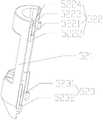
具体地,上限位槽512和下限位槽513沿同一方向延伸,上限位件522和下限位件523沿同一方向延伸;上限位槽512包括相互连通的第一上深槽5121和上浅槽5122,上限位件522包括上限位条5221和设置在上限位条5221上的第一上凸块5222,其中,上限位条5221的至少一部分插入上浅槽5122内,第一上凸块5222插入第一上深槽5121内。在进行第一夹持部51和第二夹持部52的连接时,通过第一上凸块5222和第一上深槽5121的设置能够起到限位作用,使装配更加准确。而且,由于设置有深度不同的槽,这样可通过第一上凸块5222与第一上深槽5121的侧壁的配合,在第一上深槽5121的延伸方向对第一夹持部51和第二夹持部52起到限位作用。Specifically, the upper limit groove 512 and the
进一步地,如图7和图8所示,上限位槽512还包括和上浅槽5122连通的第二上深槽5123,上浅槽5122位于第一上深槽5121和第二上深槽5123之间,上限位件522还包括悬臂梁5223和第二上凸块5224,悬臂梁5223的一端和上限位条5221连接,第二上凸块5224设置在悬臂梁5223的另一端,其中,第二上凸块5224卡入第二上深槽5123内。在第一夹持部51和第二夹持部52连接时,第一上凸块5222先与第一上深槽5121的侧壁进行配合,当第二上凸块5224碰到上浅槽5122的内壁时,由于悬臂梁5223具有弹性,从而会向靠近第二主体521的方向移动;当第二上凸块5224滑过上浅槽5122后,此时第二上凸块5224刚好能够卡在第二上深槽5123内,这样能够在轴向的上下方向均起到限位作用。具体地,第一上凸块5222设置为圆柱形结构,第一上深槽5121设置为圆柱形槽,通过第一上凸块5222和第一上深槽5121之间的配合,能够在径向起到限位作用,进一步保证了第一夹持部51和第二夹持部52连接的可靠性。Further, as shown in FIGS. 7 and 8 , the upper limit groove 512 also includes a second upper
具体地,下限位槽513包括相互连通的下深槽5131和下浅槽5132,下限位件523包括下限位条5231和设置在下限位条5231上的下凸块5232,其中,下限位条5231的至少一部分插入下浅槽5132内,下凸块5232插入下深槽5131内。通过设置下深槽5131和下浅槽5132可使下限位条5231和下凸块5232能够进行准确定位,安装更加便捷。具体地,下凸块5232设置为圆柱形结构,下深槽5131设置为圆柱形槽,通过下凸块5232和下深槽5131之间的配合,能够在径向起到限位作用,提高了第一夹持部51和第二夹持部52连接的紧固性。Specifically, the
其中,执行部30包括依次连接的转轴31、连接板32和偏置板33,转轴31可转动地设置在底座10上,偏置板33避让转轴31的轴线,转轴31的轴线穿过容纳腔53,偏置板33远离连接板32的一端和第一夹持部51连接,夹持结构50和连接板32之间具有避让空间;容纳腔53的上端具有上开口,容纳腔53的下端具有下开口,在转轴31的径向方向上,容纳腔53的中部区域的尺寸大于上开口、下开口的尺寸。避让空间可用于避让线缆等结构。将容纳腔53的上开口和下开口的尺寸设置为小于中部区域的尺寸,可对放置于容纳腔53内的内窥镜进行限位,避免内窥镜脱出。Wherein, the
如图5所示,在本实施例中,将执行部30和第一夹持部51设置为一体结构,这样可减少零件数量,便于装配。As shown in FIG. 5 , in this embodiment, the implementing
在本方案中,转轴31与底座10之间设有轴承,并且通过挡圈抵住轴承,使结构更加牢固稳定。连接板32和偏置板33的设置,使得夹持结构50的转动中心与转轴31的转动中心位于同一条直线上,如此设置,可使内窥镜的转动中心与转轴31的转动中心重合,便于内窥镜的转动控制(即仅绕着转轴31自转,不会带来其他的位置改变)。In this solution, a bearing is provided between the
具体地,转轴31上具有两个螺旋槽,两个螺旋槽的旋向相反,第一拉绳41和第二拉绳42的另一端分别缠绕在两个螺旋槽上。转轴31上还具有两个限位孔,第一拉绳41和第二拉绳42的端部分别穿过两个限位孔。螺旋槽的设置可使第一拉绳41和第二拉绳42在运行中更加稳定,限位孔可使第一拉绳41和第二拉绳42与转轴31的连接更加紧固可靠。Specifically, the rotating
在本实施例中,内窥镜传动盒还包括固定板80,固定板80和底座10连接,底座10包括底板11和设置在底板11上的下支柱12,固定板80包括顶板81和设置在顶板81上的上支柱82,其中,下支柱12和顶板81连接,上支柱82和底板11连接。下支柱12和顶板81可通过螺栓方式连接,易于拆卸;上支柱82和底板11也可采用螺栓方式连接,安装便利。通过固定板80和底座10能够可靠地对传动部20和执行部30进行支撑。In this embodiment, the endoscope drive box also includes a fixed
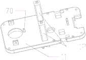
进一步地,内窥镜传动盒还包括外壳91,外壳91罩住固定板80,外壳91和底板11连接。外壳91与底板11可采用卡接方式连接,容易安装和拆卸。内窥镜传动盒还包括安装板、驱动部,驱动部设置在安装板上,驱动部与传动部20驱动连接。内窥镜传动盒还包括设置在安装板上的卡钩,卡钩和底座10卡接,从而实现安装板和底座10的连接。Further, the endoscope transmission box further includes a
如图3所示,内窥镜传动盒还包括压杆92,压杆92可转动地设置在底座10上,压杆92在转动时推动卡钩,以使卡钩和底座10脱离。内窥镜传动盒还包括弹性件93,弹性件93的一端和固定板80抵接,弹性件93的另一端和压杆92抵接。在操作时,按压压杆92,压杆92克服弹性件93的弹力后转动,从而推动卡钩移动。其中,弹性件93中设置有杆件,用于支撑弹性件93,防止脱落。As shown in FIG. 3 , the endoscope transmission box further includes a
进一步地,内窥镜传动盒还包括连接轴94,底板11上设置有凸柱13,连接轴94穿过压杆92,连接轴94的一端与凸柱13铰接,连接轴94的另一端和外壳91铰接,在按压压杆92时,通过连接轴94使压杆92转动。Further, the endoscope drive box also includes a connecting
本发明的另一实施例提供了一种微创手术机器人,微创手术机器人包括上述的内窥镜传动盒。微创手术机器人由医生控制台、手术臂系统组成,其中手术臂系统由多个持械臂和一个持镜臂组成,持镜臂上安装有内窥镜传动盒,从而移动和操作内窥镜传动盒。Another embodiment of the present invention provides a minimally invasive surgical robot, which includes the above-mentioned endoscope transmission box. The minimally invasive surgical robot is composed of a doctor's console and an operating arm system. The operating arm system is composed of multiple arms and a mirror arm. The endoscope transmission box is installed on the mirror arm to move and operate the endoscope. Transmission box.
以上所述仅为本发明的优选实施例而已,并不用于限制本发明,对于本领域的技术人员来说,本发明可以有各种更改和变化。凡在本发明的精神和原则之内,所作的任何修改、等同替换、改进等,均应包含在本发明的保护范围之内。The above descriptions are only preferred embodiments of the present invention, and are not intended to limit the present invention. For those skilled in the art, the present invention may have various modifications and changes. Any modifications, equivalent replacements, improvements, etc. made within the spirit and principles of the present invention shall be included within the protection scope of the present invention.
Claims (10)
Translated fromChinesePriority Applications (1)
| Application Number | Priority Date | Filing Date | Title |
|---|---|---|---|
| CN202211415657.5ACN115737125A (en) | 2021-08-04 | 2021-08-04 | Endoscope transmission box and minimally invasive surgery robot |
Applications Claiming Priority (2)
| Application Number | Priority Date | Filing Date | Title |
|---|---|---|---|
| CN202110893558.7ACN113693728A (en) | 2021-08-04 | 2021-08-04 | Endoscope transmission box and minimally invasive surgery robot |
| CN202211415657.5ACN115737125A (en) | 2021-08-04 | 2021-08-04 | Endoscope transmission box and minimally invasive surgery robot |
Related Parent Applications (1)
| Application Number | Title | Priority Date | Filing Date |
|---|---|---|---|
| CN202110893558.7ADivisionCN113693728A (en) | 2021-08-04 | 2021-08-04 | Endoscope transmission box and minimally invasive surgery robot |
Publications (1)
| Publication Number | Publication Date |
|---|---|
| CN115737125Atrue CN115737125A (en) | 2023-03-07 |
Family
ID=78651620
Family Applications (2)
| Application Number | Title | Priority Date | Filing Date |
|---|---|---|---|
| CN202211415657.5APendingCN115737125A (en) | 2021-08-04 | 2021-08-04 | Endoscope transmission box and minimally invasive surgery robot |
| CN202110893558.7APendingCN113693728A (en) | 2021-08-04 | 2021-08-04 | Endoscope transmission box and minimally invasive surgery robot |
Family Applications After (1)
| Application Number | Title | Priority Date | Filing Date |
|---|---|---|---|
| CN202110893558.7APendingCN113693728A (en) | 2021-08-04 | 2021-08-04 | Endoscope transmission box and minimally invasive surgery robot |
Country Status (1)
| Country | Link |
|---|---|
| CN (2) | CN115737125A (en) |
Families Citing this family (1)
| Publication number | Priority date | Publication date | Assignee | Title |
|---|---|---|---|---|
| CN115721246A (en)* | 2022-11-22 | 2023-03-03 | 杭州唯精医疗机器人有限公司 | Endoscope transmission device and surgical robot |
Citations (5)
| Publication number | Priority date | Publication date | Assignee | Title |
|---|---|---|---|---|
| JP2005013320A (en)* | 2003-06-24 | 2005-01-20 | Olympus Corp | Endoscope |
| US20100274078A1 (en)* | 2009-04-27 | 2010-10-28 | Kwang-Gi Kim | Endoscope manipulator for minimally invasive surgery |
| CN102119872A (en)* | 2011-01-10 | 2011-07-13 | 天津大学 | Compact quick-change mechanism of robot for minimally invasive surgery |
| US20120065470A1 (en)* | 2010-09-14 | 2012-03-15 | The Johns Hopkins University | Robotic system to augment endoscopes |
| CN109528304A (en)* | 2019-01-22 | 2019-03-29 | 绵阳美科电子设备有限责任公司 | Manipulate the device and its application method of endoscope |
Family Cites Families (3)
| Publication number | Priority date | Publication date | Assignee | Title |
|---|---|---|---|---|
| US9050120B2 (en)* | 2007-09-30 | 2015-06-09 | Intuitive Surgical Operations, Inc. | Apparatus and method of user interface with alternate tool mode for robotic surgical tools |
| CN107260312B (en)* | 2017-07-31 | 2023-09-19 | 成都博恩思医学机器人有限公司 | Transmission assembly, surgical instrument of surgical robot and surgical robot |
| CN108338841B (en)* | 2018-04-17 | 2021-03-23 | 成都博恩思医学机器人有限公司 | A mirror-holding robot system for laparoscopic surgery |
- 2021
- 2021-08-04CNCN202211415657.5Apatent/CN115737125A/enactivePending
- 2021-08-04CNCN202110893558.7Apatent/CN113693728A/enactivePending
Patent Citations (5)
| Publication number | Priority date | Publication date | Assignee | Title |
|---|---|---|---|---|
| JP2005013320A (en)* | 2003-06-24 | 2005-01-20 | Olympus Corp | Endoscope |
| US20100274078A1 (en)* | 2009-04-27 | 2010-10-28 | Kwang-Gi Kim | Endoscope manipulator for minimally invasive surgery |
| US20120065470A1 (en)* | 2010-09-14 | 2012-03-15 | The Johns Hopkins University | Robotic system to augment endoscopes |
| CN102119872A (en)* | 2011-01-10 | 2011-07-13 | 天津大学 | Compact quick-change mechanism of robot for minimally invasive surgery |
| CN109528304A (en)* | 2019-01-22 | 2019-03-29 | 绵阳美科电子设备有限责任公司 | Manipulate the device and its application method of endoscope |
Also Published As
| Publication number | Publication date |
|---|---|
| CN113693728A (en) | 2021-11-26 |
Similar Documents
| Publication | Publication Date | Title |
|---|---|---|
| CN215458618U (en) | Operation robot rotates coupling assembling, telecentric control mechanism and operation robot | |
| JP5245010B2 (en) | Endoscope bending operation device, endoscope | |
| CN111134850B (en) | Drive box, operation arm and surgical robot | |
| JPWO2013061690A1 (en) | Endoscope bending operation device | |
| RU2763502C2 (en) | Connecting block | |
| CN115737125A (en) | Endoscope transmission box and minimally invasive surgery robot | |
| WO2023115851A1 (en) | Disposable flexible endoscope | |
| CN112472162B (en) | Surgical instruments and surgical robots | |
| WO2023216711A1 (en) | Disposable section and reusable section of endoscope handle and endoscope | |
| CN113693729B (en) | Instrument driving box and minimally invasive surgery robot | |
| CN111685878A (en) | Bayonet structure of needle holder and needle holder control assembly | |
| CN112472161B (en) | Surgical instruments and surgical robots | |
| CN221635867U (en) | Multi-degree-of-freedom joint assembly and endoscopic instrument | |
| CN217390868U (en) | Easy-to-install instrument drive assemblies and robotic surgery systems | |
| CN117159150A (en) | Laparoscopic surgical instrument and surgical robot | |
| CN116421307A (en) | Anti-shake instrument drive assembly and robotic surgical system | |
| CN214434487U (en) | Surgical instrument, actuator and surgical robot | |
| JP4643721B2 (en) | Endoscope angle control device | |
| CN214434486U (en) | Actuating mechanism and surgical robot | |
| CN221963732U (en) | Endoscope switching device and endoscope operation robot | |
| CN114587595A (en) | Surgical instrument, actuator and surgical robot | |
| CN217390860U (en) | Anti-shake instrument drive assembly and robotic surgery system | |
| CN119606542B (en) | Wire drive device and surgical robot | |
| CN219021095U (en) | Endoscope and its handle | |
| CN217219191U (en) | Anti-shake instrument drive assembly and robotic surgery system |
Legal Events
| Date | Code | Title | Description |
|---|---|---|---|
| PB01 | Publication | ||
| PB01 | Publication | ||
| SE01 | Entry into force of request for substantive examination | ||
| SE01 | Entry into force of request for substantive examination | ||
| TA01 | Transfer of patent application right | Effective date of registration:20240815 Address after:310000, Floor 1, Building 1 and 1-4, Building 2, No. 39, Keji Avenue, Yuhang Street, Yuhang District, Hangzhou City, Zhejiang Province Applicant after:Hangzhou Weijing medical robot Co.,Ltd. Country or region after:China Address before:213023 No. g064, Changzhou Zhonglou hi tech entrepreneurship service center, No. 213, Yulong South Road, Zhonglou Economic Development Zone, Changzhou City, Jiangsu Province Applicant before:Changzhou Weijing medical robot Co.,Ltd. Country or region before:China | |
| TA01 | Transfer of patent application right | ||
| CB02 | Change of applicant information | Country or region after:China Address after:311121 Hangzhou City, Yuhang District, Yuhang Street, Keji Avenue 39, Building 1, first floor, Building 2, first to fourth floors Applicant after:Hangzhou Kangji Weijing Medical Robot Co.,Ltd. Address before:Building 1, 1st Floor, and Building 2, 1-4 Floors, No. 39 Keji Avenue, Yuhang Street, Yuhang District, Hangzhou City, Zhejiang Province Applicant before:Hangzhou Weijing medical robot Co.,Ltd. Country or region before:China | |
| CB02 | Change of applicant information |