CN115737022A - Rib retractor - Google Patents
Rib retractorDownload PDFInfo
- Publication number
- CN115737022A CN115737022ACN202211544371.7ACN202211544371ACN115737022ACN 115737022 ACN115737022 ACN 115737022ACN 202211544371 ACN202211544371 ACN 202211544371ACN 115737022 ACN115737022 ACN 115737022A
- Authority
- CN
- China
- Prior art keywords
- arm
- supporting
- baffle
- rib retractor
- plate
- Prior art date
- Legal status (The legal status is an assumption and is not a legal conclusion. Google has not performed a legal analysis and makes no representation as to the accuracy of the status listed.)
- Pending
Links
Images


Landscapes
- Surgical Instruments (AREA)
Abstract
Description
Translated fromChinese技术领域technical field
本发明涉及心胸外科手术器械技术领域,尤其涉及一种肋骨牵开器。The invention relates to the technical field of cardiothoracic surgical instruments, in particular to a rib retractor.
背景技术Background technique
肋骨是一种参与构成人体胸廓的扁骨,由肋头、肋颈、肋体等结构组成,肋骨内面近下缘处有肋沟,其间有肋间神经和血管。肋骨有着抗外力击打的作用,可以保护重要的胸廓内脏器如心、肺、大血管。当对罹患心肺疾病的患者进行开胸直视手术或对急诊患者进行紧急开胸手术探查时,临床医生为了获得良好的手术视野和足够的操作空间,依次切开皮肤、皮下组织、肌肉,暴露手术目标时,需要应用肋骨牵开器增大上下位肋骨之间的空隙,以便手术的进行。目前针对牵开肋骨扩大视野至胸腔内的器械已经十分成熟,但是对于需要暴露壁层胸膜侧的手术还没有合适的器械。The rib is a kind of flat bone that participates in the formation of the human thorax. It is composed of rib head, rib neck, rib body and other structures. There is a rib groove near the lower edge of the inner surface of the rib, and there are intercostal nerves and blood vessels in between. The ribs have the function of resisting external force and can protect important thoracic internal organs such as the heart, lungs, and great blood vessels. When performing thoracotomy on patients suffering from cardiopulmonary diseases or performing emergency thoracotomy exploration on emergency patients, in order to obtain a good surgical field of view and sufficient operating space, clinicians incise the skin, subcutaneous tissue, and muscles in sequence, exposing For the purpose of surgery, it is necessary to use a rib retractor to increase the space between the upper and lower ribs to facilitate the operation. At present, the instruments for expanding the field of view into the thoracic cavity by distracting the ribs are very mature, but there is no suitable instrument for the operation that needs to expose the parietal pleural side.
传统暴露胸腔的肋骨牵开器主要由齿条、固定臂、移动臂组成,固定臂和移动臂一端连接在齿条上,另一端伸入胸内与肋骨接触,通过手动调节移动臂与固定臂之间的距离,将上下位肋骨进行反向迁开,达到撑开上下位肋骨的目的。但是,这种肋骨牵开器仅能够在平行于胸壁平面的方向为肋骨施加两个相反的作用力,促使上下两根肋骨分离,从而暴露胸腔,而不能够在垂直与胸壁的方向作用于肋骨,上下肋骨无法形成高度落差,不能充分暴露壁层胸膜处的胸壁。The traditional rib retractor for exposing the chest is mainly composed of a rack, a fixed arm, and a movable arm. One end of the fixed arm and the movable arm is connected to the rack, and the other end extends into the chest to contact the ribs. Manually adjust the movable arm and the fixed arm. Move the upper and lower ribs in reverse to achieve the purpose of stretching the upper and lower ribs. However, this rib retractor can only apply two opposite forces to the ribs in a direction parallel to the plane of the chest wall to separate the upper and lower ribs, thereby exposing the chest cavity, but cannot act on the ribs in a direction perpendicular to the chest wall. , the upper and lower ribs cannot form a height difference, and the chest wall at the parietal pleura cannot be fully exposed.
发明内容Contents of the invention
为了解决现有技术存在的上述问题,本发明的目的在于提供一种肋骨牵开器,能够在撑开上下位肋骨的同时,也能使上下肋骨之间形成高度差,从而更充分的暴露壁层胸膜内测胸壁,方便手术医生对于内测胸壁进行手术操作。In order to solve the above-mentioned problems existing in the prior art, the object of the present invention is to provide a rib retractor, which can form a height difference between the upper and lower ribs while stretching the upper and lower ribs, thereby more fully exposing the rib retractor. The chest wall is measured inside the layer of pleura, which is convenient for the surgeon to perform operations on the inner chest wall.
为了解决上述技术问题,本发明采用的技术方案如下:一种肋骨牵开器,包括:In order to solve the above technical problems, the technical solution adopted in the present invention is as follows: a rib retractor, comprising:
支撑板;support plate;
第一撑开臂,所述第一撑开臂的一端与支撑板的一端连接且所述第一撑开臂与支撑板垂直设置;a first stretching arm, one end of the first stretching arm is connected to one end of the support plate and the first stretching arm is perpendicular to the support plate;
动组件,所述活动组件套设在支撑板上且可沿着支撑板的长度方向移动并能实现定位;A moving assembly, the moving assembly is sleeved on the support plate and can move along the length direction of the support plate and can realize positioning;
第二撑开臂,所述第二撑开臂与活动组件的内侧外壁连接,且第二撑开臂与第一撑开臂平行设置;a second spreading arm, the second spreading arm is connected to the inner outer wall of the movable component, and the second spreading arm is arranged in parallel with the first spreading arm;
第一挡板,所述第一挡板活动设置在第一撑开臂的下方;a first baffle, and the first baffle is movably arranged under the first spreading arm;
调节组件,所述调节组件的一端套设在第一撑开臂上且与第一挡板的顶部铰接,所述调节组件的另一端设置有支撑旋钮,所述支撑旋钮可沿其轴线方向移动,所述支撑旋钮的一端穿过调节组件后抵接在第一挡板上;An adjustment assembly, one end of the adjustment assembly is sleeved on the first spreader arm and hinged to the top of the first baffle, the other end of the adjustment assembly is provided with a support knob, and the support knob can move along its axis , one end of the support knob passes through the adjustment assembly and abuts against the first baffle;
第二挡板,所述第二挡板的一端套设在第二撑开臂上。The second baffle, one end of the second baffle is sheathed on the second spreading arm.
作为本发明的进一步改进,所述调节组件包括:As a further improvement of the present invention, the adjustment assembly includes:
第一铰接板,所述第一铰接板分别对称设置在第一挡板靠近第一撑开臂一侧的顶端;a first hinged plate, the first hinged plates are respectively symmetrically arranged on the top of the first baffle on the side close to the first spreader arm;
支撑座,所述支撑座的一端位于两块第一铰接板之间且与第一铰接板铰接,支撑座位于铰接端的一端横向贯穿设置有与第一撑开臂相适配的第一滑动槽,支撑座远离第一撑开臂的一端顶部贯穿设置有螺纹孔;A support seat, one end of the support seat is located between two first hinged plates and is hinged to the first hinge plate, and one end of the support seat located at the hinged end is transversely provided with a first sliding groove adapted to the first spreader arm , a threaded hole is provided through the top of the end of the support seat away from the first spreading arm;
所述支撑旋钮上设置有与螺纹孔相匹配的螺纹,所述支撑旋钮贯穿螺纹孔后抵接在第一挡板的顶端。The support knob is provided with threads matching the threaded holes, and the support knob abuts against the top of the first baffle plate after passing through the threaded holes.
作为本发明的进一步改进,所述支撑旋钮的顶端设置有旋转手柄。As a further improvement of the present invention, a rotating handle is provided at the top of the support knob.
作为本发明的进一步改进,两块所述第一铰接板以及支撑座的一端均横向开设有同轴设置的轴孔,轴孔内插入有轴销。As a further improvement of the present invention, the two first hinged plates and one end of the support seat are provided with coaxial shaft holes transversely, and shaft pins are inserted into the shaft holes.
作为本发明的进一步改进,所述支撑座远离第一撑开臂的一端顶部设置有贯穿的通孔。As a further improvement of the present invention, a through hole is provided on the top of the end of the support seat away from the first spreading arm.
作为本发明的进一步改进,所述第一挡板包括依次连接的第一牵拉端、连接端以及支撑端,所述第一铰接板设置在连接端的顶部且靠近第一牵拉端的一侧,所述支撑端的自由端向内翻折,所述第一牵拉端的自由端向外翻折,所述第一牵拉端的高度大于支撑端的高度。As a further improvement of the present invention, the first baffle includes a first pulling end, a connecting end and a supporting end connected in sequence, and the first hinge plate is arranged on the top of the connecting end and on a side close to the first pulling end, The free end of the supporting end is turned inward, the free end of the first pulling end is turned outward, and the height of the first pulling end is greater than that of the supporting end.
作为本发明的进一步改进,所述第一牵拉端的自由端向外翻折的角度为100-120度。As a further improvement of the present invention, the angle at which the free end of the first pulling end is turned outward is 100-120 degrees.
作为本发明的进一步改进,所述第二挡板包括依次连接的滑动端和第二牵拉端,所述滑动端横向贯穿设置有与第二撑开相适配的第三滑动槽,所述第二牵拉端的自由端向外翻折。As a further improvement of the present invention, the second baffle plate includes a sliding end and a second pulling end connected in sequence, and a third sliding groove adapted to the second expansion is arranged transversely through the sliding end, and the The free end of the second pulling end is turned outward.
作为本发明的进一步改进,所述滑动端与第二牵拉端之间的夹角为100-120度。As a further improvement of the present invention, the angle between the sliding end and the second pulling end is 100-120 degrees.
作为本发明的进一步改进,所述支撑板的长度方向上设置有齿条,所述活动组件包括:As a further improvement of the present invention, a rack is provided on the length direction of the support plate, and the movable assembly includes:
滑动块,所述滑动块横向贯穿设置有与支撑板相适配的第二滑动槽;A sliding block, the second sliding groove adapted to the support plate is arranged transversely through the sliding block;
转轴,所述转轴的一端贯穿滑动块的顶端后插入第二滑动槽内;A rotating shaft, one end of which passes through the top of the sliding block and is inserted into the second sliding groove;
槽轮,所述槽轮设置在第二滑动槽内与齿条啮合,且所述槽轮设置在转轴插入第二滑动槽内的一端;A sheave, the sheave is arranged in the second sliding groove to mesh with the rack, and the sheave is arranged at one end of the rotating shaft inserted into the second sliding groove;
限位手柄,所述限位手柄与转轴远离槽轮的一端连接。A limit handle, the limit handle is connected with the end of the rotating shaft away from the sheave.
作为本发明的进一步改进,还包括限制活动组件向靠近第一撑开臂方向滑动的锁止机构。As a further improvement of the present invention, it also includes a locking mechanism that restricts the movable assembly from sliding toward the direction of approaching the first spreading arm.
作为本发明的进一步改进,所述锁止机构安装在在滑动块顶端开设的凹槽内。As a further improvement of the present invention, the locking mechanism is installed in a groove provided at the top of the sliding block.
作为本发明的进一步改进,所述锁止机构包括限位板以及安装在限位板底部左右两端的限位弹簧和限位块,所述支撑板的顶端沿着支撑板的长度方向间隔设置有若干个与限位块相适配的限位槽,所述限位板沿着限位板长度方向的外侧壁与凹槽的内壁铰接,所述限位块远离限位板的一端贯穿凹槽的底部后延伸至限位槽内。As a further improvement of the present invention, the locking mechanism includes a limit plate, limit springs and limit blocks installed at the left and right ends of the bottom of the limit plate, and the top of the support plate is arranged at intervals along the length direction of the support plate. A plurality of limit slots adapted to the limit block, the outer wall of the limit plate along the length direction of the limit plate is hinged to the inner wall of the groove, and the end of the limit block away from the limit plate penetrates the groove The bottom of the back extends into the limit groove.
作为本发明的进一步改进,所述限位槽为楔形槽。As a further improvement of the present invention, the limiting groove is a wedge-shaped groove.
作为本发明的进一步改进,所述凹槽的下方且位于限位弹簧的底部开设有容纳限位弹簧的固定槽。As a further improvement of the present invention, a fixing groove for accommodating the limiting spring is provided under the groove and at the bottom of the limiting spring.
作为本发明的进一步改进,所述固定槽的高度小于限位弹簧的高度。As a further improvement of the present invention, the height of the fixing groove is smaller than the height of the limit spring.
本发明与现有技术相比,具有如下有益效果:Compared with the prior art, the present invention has the following beneficial effects:
1、本发明一种肋骨牵开器,通过活动组件调节第一撑开臂与第二撑开臂调之间的间距以及通过调节组件带动第一挡板在竖直方向上移动,从而在撑开上下位肋骨的同时,也能使上下肋骨之间形成高度差,从而更充分的暴露了壁层胸膜内测胸壁,方便了手术医生对于内测胸壁进行手术操作。1. A rib retractor of the present invention adjusts the distance between the first spreading arm and the second spreading arm through the movable component and drives the first baffle plate to move in the vertical direction through the adjusting component, so that While opening the upper and lower ribs, it can also form a height difference between the upper and lower ribs, thereby more fully exposing the inner chest wall of the parietal pleura, which is convenient for the surgeon to operate on the inner chest wall.
2、本发明一种肋骨牵开器,通过设置限制活动组件向靠近第一撑开臂方向滑动的锁止机构,从而更加稳定的暴露胸腔,从而进一步提高了整体装置在术中的稳定性。2. A rib retractor of the present invention is provided with a locking mechanism that restricts the movable component from sliding toward the first spreading arm, thereby exposing the chest cavity more stably, thereby further improving the stability of the whole device during operation.
附图说明Description of drawings
图1为本发明肋骨牵开器整体结构示意图;Fig. 1 is the overall structure schematic diagram of rib retractor of the present invention;
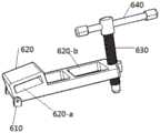
图2为本发明肋骨牵开器中调节组件结构示意图;Fig. 2 is a structural schematic diagram of the adjustment assembly in the rib retractor of the present invention;
图3为本发明肋骨牵开器中活动组件整体结构示意图;Fig. 3 is a schematic diagram of the overall structure of the movable assembly in the rib retractor of the present invention;
图4为本发明肋骨牵开器中位手柄、转轴与槽轮连接结构示意图;Fig. 4 is a schematic diagram of the connecting structure of the neutral handle, the rotating shaft and the sheave of the rib retractor of the present invention;
图5为本发明肋骨牵开器中第一挡板结构示意图;Fig. 5 is a structural schematic diagram of the first baffle plate in the rib retractor of the present invention;
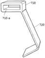
图6为本发明肋骨牵开器中第二挡板结构示意图;Fig. 6 is the structural schematic diagram of the second baffle plate in the rib retractor of the present invention;
图7为本发明肋骨牵开器整体结构俯视图;7 is a top view of the overall structure of the rib retractor of the present invention;
图8为本发明肋骨牵开器带有锁止机构的整体结构示意图;Fig. 8 is a schematic diagram of the overall structure of the rib retractor of the present invention with a locking mechanism;
图9为本发明肋骨牵开器中锁止机构结构示意图;Fig. 9 is a structural schematic diagram of the locking mechanism in the rib retractor of the present invention;
图10为本发明肋骨牵开器锁止机构与滑动块连接剖视图。Fig. 10 is a sectional view of the connection between the locking mechanism and the sliding block of the rib retractor of the present invention.
附图中:In the attached picture:
100、支撑板;110、齿条;100-a、限位槽;100, support plate; 110, rack; 100-a, limit groove;
200、第一撑开臂;200. The first stretching arm;
300、活动组件;310、滑动块;310-a、第二滑动槽;310-b、凹槽; 310-c、固定槽;320、转轴;330、槽轮;340、限位手柄;300, movable assembly; 310, sliding block; 310-a, second sliding groove; 310-b, groove; 310-c, fixed groove; 320, rotating shaft; 330, sheave; 340, limit handle;
400、第二撑开臂;400, the second stretching arm;
500、第一挡板;510、第一牵拉端;520、连接端;530、支撑端;500, the first baffle; 510, the first pulling end; 520, the connecting end; 530, the supporting end;
600、调节组件;610、第一铰接板;620、支撑座;620-a、第一滑动槽;620-b、通孔;630、支撑旋钮;600, adjustment assembly; 610, first hinge plate; 620, support seat; 620-a, first sliding groove; 620-b, through hole; 630, support knob;
700、第二挡板;710、滑动端;720、第二牵拉端;700, the second baffle; 710, the sliding end; 720, the second pulling end;
800、锁止机构;810、限位板;820、限位弹簧;830、限位块;840、按压槽;850、第二铰接板。800, locking mechanism; 810, limit plate; 820, limit spring; 830, limit block; 840, pressing groove; 850, second hinge plate.
具体实施方式Detailed ways
下面将结合本发明实施例中的附图,对本发明实施例中的技术方案进行清楚、完整地描述,显然,所描述的实施例仅仅是本发明一部分实施例,而不是全部的实施例。基于本发明中的实施例,本领域普通技术人员在没有做出创造性劳动前提下所获得的所有其他实施例,都属于本发明保护的范围。The following will clearly and completely describe the technical solutions in the embodiments of the present invention with reference to the accompanying drawings in the embodiments of the present invention. Obviously, the described embodiments are only some, not all, embodiments of the present invention. Based on the embodiments of the present invention, all other embodiments obtained by persons of ordinary skill in the art without making creative efforts belong to the protection scope of the present invention.
实施例1Example 1
图1至图7示出的是本发明一种肋骨牵开器一实施方式的结构示意图,其主体部分包括支撑板100、第一撑开臂200、活动组件300、第二撑开臂400、第一挡板500、调节组件600和第二挡板700。Figures 1 to 7 show a schematic structural view of an embodiment of a rib retractor of the present invention, the main body of which includes a
支撑板100用于活动组件300 和调节组件600的组装,支撑板100的长度方向设置有齿条110。The
第一撑开臂200一端与支撑板100的一端连接且所述第一撑开臂200与支撑板100垂直设置。作为优选,在本实施方式中,支撑板100和第一撑开臂200为一体成型的L形板材,第一撑开臂200与支撑板100一端的端部垂直连接。One end of the first spreading
活动组件300套设在支撑板100上且可沿着支撑板100的长度方向移动并能实现定位,活动组件300用来调节第二撑开臂400与第一撑开臂200之间的间距。具体的,活动组件300包括滑动块310、转轴320、槽轮330和限位手柄340。活动组件300通过滑动块310与支撑板100之间的摩擦力实现进行限位。滑动块310横向贯穿设置有与支撑板100相适配的第二滑动槽310-a,转轴320的一端贯穿滑动块310的顶端后插入第二滑动槽310-a内,槽轮330设置在第二滑动槽310-a内与齿条110啮合,且所述槽轮330设置在转轴320插入第二滑动槽310-a内的一端,限位手柄340与转轴320远离槽轮330的一端连接。在本实施方式中,当限位手柄340带动转轴320与槽轮330同步转动时,滑动块310沿着齿条110直线移动,从而同步带动第二撑开臂400与第二挡板700向着第一撑开臂200和第一挡板500的方向靠近或者远离。在术中时,通过转动限位手柄340使第二撑开臂400与第一撑开臂200相互远离,此时平行于胸壁平面的方向为肋骨施加两个相反的作用力,第二挡板700与第一挡板500将手术肋间切口牵开,促使上下两根肋骨分离,从而暴露了胸腔,提供了良好的手术视野。作为优选,在本实施方式中,限位手柄340与转轴320铰接,在使用的先将限位手柄340向下翻,使限位手柄340与支撑板100平行,再转动限位手柄340,待位置确定好后,将限位手柄340向上翻起,进行限位固定。The
第二撑开臂400用来带动第二挡板700的移动,第二撑开臂400与活动组件300的内侧外壁连接,且第二撑开臂400与第一撑开臂200平行设置。在本实施方式中,当活动组件300向远离第一撑开臂200的方向移动时,第一撑开臂200与第二撑开臂之间的间隔逐渐变大,从而将下位肋骨与上位肋骨反向牵拉。The second spreading
第一挡板500用于对上位肋骨的牵拉,活动设置在第一撑开臂200的下方。具体的,第一挡板500包括依次连接的第一牵拉端510、连接端520以及支撑端530,所述第一铰接板610设置在连接端520的顶部且靠近第一牵拉端510的一侧,支撑端530的自由端向内翻折,所述第一牵拉端510的自由端向外翻折,第一牵拉端510向外翻折的角度可以设置为100-120度, 从而提高第一挡板500对上位肋骨向上的牵拉力。第一牵拉端510的高度大于支撑端530的高度,当支撑旋钮630向下移动时,带动第一牵拉端510向上移动。在术中时,将第一牵拉端510放置于上位肋骨的一侧,将支撑端530放置在患者皮肤表面,支撑端530的纵截面整体呈J形,圆滑平顺,一方面从而使支撑端530与患者皮肤接触时不会划伤患者,也能够有效的打开上下位肋骨,同时形成上下落差,对于一些非胸腔内,而是靠近壁层胸膜的手术能够提供清晰的视野。The
调节组件600用于调节第一挡板500在垂直方向上移动,调节组件600的一端套设在第一撑开臂200上且与第一挡板500的顶部铰接,调节组件600的另一端设置有支撑旋钮630,所述支撑旋钮630可沿其轴线方向移动,所述支撑旋钮630的一端穿过调节组件600后抵接在第一挡板500上。具体的,调节组件600包括第一铰接板610、支撑座620和旋转手柄640。第一铰接板610分别对称设置在第一挡板500靠近第一撑开臂200一侧的顶端,支撑座620一端位于两块第一铰接板610之间且与第一铰接板610铰接,支撑座620位于铰接端的一端横向贯穿设置有与第一撑开臂200相适配的第一滑动槽620-a,支撑座620远离第一撑开臂200的一端顶部贯穿设置有螺纹孔,支撑旋钮630上设置有与螺纹孔相匹配的螺纹,支撑旋钮630贯穿支撑座620顶部的螺纹孔后抵接在第一挡板500的顶端,支撑旋钮630的顶端设置有旋转手柄640。当支撑旋钮630向下移动时,带动第一挡板500靠近第一撑开臂200的一端向上移动。两块所述第一铰接板610以及支撑座620的一端均横向开设有同轴设置的轴孔,轴孔内插入有轴销,使第一挡板500可以相对于支撑座620进行摆动。在使用时,第一牵拉端510与支撑端530在支撑旋钮630和支撑座620的作用下形成杠杆作用,支撑旋钮630的底端通过支撑座620抵接在连接端520的顶部,通过转动旋转手柄640使支撑旋钮630向下移动,从而带动第一牵拉端510向上移动,从而将上位肋骨向上牵拉,在垂直与胸壁的方向作用于肋骨,使上下肋骨形成高度落差,充分暴露了壁层胸膜处的胸壁。作为优选,在本实施方式中,为了减轻整体调节组件600整体的重量,在支撑座620远离第一撑开臂200的一端顶部设置有贯穿的通孔620-b。The
第二挡板700用来对下位肋骨的牵拉,第二挡板700包括依次连接的滑动端710和第二牵拉端720,滑动端710横向贯穿设置有与第二撑开臂400相适配的第三滑动槽710-a,滑动端710套设在第二撑开臂400上,并且可沿着第二撑开臂400的长度方向滑动,在术中可以随时滑动滑动端710,从而调整第二挡板700最佳的牵拉位置。第二牵拉端720的自由端设置为向外翻折,使第一牵拉端510与二牵拉端720都向外翻折实现对上下位肋骨的牵拉,第二牵拉端720翻折的角度可以设置为90度。作为优选,在本实施方式中,为了实现第二挡板700对下位肋骨向下的牵拉力,将滑动端710与第二牵拉端720之间的夹角设置为100-120度,从而实现对下位肋骨向后和向下的牵拉。The
结合图1至图7,本实施方式的一种肋骨牵开器,具体实施过程如下:With reference to Fig. 1 to Fig. 7, a rib retractor of this embodiment, the specific implementation process is as follows:
使用时,首先将第二挡板700套设在第二撑开臂400上,调节组件600套设在第一撑开臂200上,然后转动限位手柄340带动转轴320与槽轮330同步转动,从而带动滑动块310沿着齿条110向着第一撑开臂200的方向移动,从而将第二撑开臂400与第一撑开臂200靠拢待用。当需要使用牵开器时,按手术的要求,选择合适的切口部位,将已装配好的的牵开器放置于肋间切口。其中,将第二挡板700放置在下位肋骨的一侧,将第一挡板500放置在上位肋骨的一侧。转动转动限位手柄340使第二撑开臂400与第一撑开臂200相互远离,通过第二挡板700与第一挡板500将手术肋间切口牵开,此时平行于胸壁平面的方向为肋骨施加两个相反的作用力,促使上下两根肋骨分离,从而暴露胸腔。接着,通过转动旋转手柄640使支撑旋钮630向下移动,带动第一挡板500靠近第一撑开臂200的一端向上移动,从而使第一牵拉端510将上位肋骨向上牵拉,在垂直与胸壁的方向作用于肋骨,使上下肋骨形成高度落差,使本肋骨牵开器不仅能平行于胸壁平面的方向为肋骨施加两个相反的作用力,也能在垂直与胸壁的方向作用于肋骨,从而更充分的暴露壁层胸膜内测胸壁,方便了手术医生对于内测胸壁进行手术操作。When in use, first set the
实施例2Example 2
如图8至图10所示,实施例2在实施例1的基础上,为了限制活动组件300向靠近第一撑开臂200方向滑动,增加了锁止机构800。在本实施方式中,第一挡板500和第二挡板700对上下位肋骨进行牵拉的过程中,上下位肋骨也对第一挡板500和第二挡板700施加反作用力,此时滑动块310可能会出现微小的滑动现象,所以在活动组件300上设置锁止机构,从而在第一挡板500和第二挡板700对上下肋骨进行牵拉的时候进一步对活动组件300进行限位,限制第二挡板700向第一挡板500靠近,从而减少牵拉效果。滑动块310顶端开设有凹槽310-b,锁止机构800活动安装在凹槽310-b。具体的,锁止机构800包括限位板810以及安装在限位板810底部左右两端的限位弹簧820和限位块830,支撑板100的顶端沿着支撑板100的长度方向间隔设置有若干个与限位块830相适配的限位槽100-a,限位槽100-a等间距设置在支撑板100的顶端,且远离齿条110的一端设置。限位板810沿着限位板810长度方向的外侧壁通过第二铰接板850与凹槽310-b的内壁铰接,使限位板810的左右两端可以相对于铰接端上下移动。第二铰接板850设置为两块,分别对称设置在凹槽310-b的顶端,限位块830远离限位板810的一端贯穿凹槽310-b的底部后延伸至限位槽100-a内,限位块830的底端依次贯穿凹槽310-b、第二滑动槽310-a后延伸至限位槽100-a内。在使用时,当第二挡板700与第一挡板500将手术肋间切口牵开时,松开限位板810位于限位弹簧820的一端,此时限位弹簧820恢复弹性形变,在限位弹簧820的作用下,限位块830向下移动,当限位块830的底端位于限位槽100-a内时,限位槽100-a限制了限位块830向靠近第一撑开臂200方向移动,即限制了滑动块310、第二撑开臂400和第二挡板700在术中时向靠近第一撑开臂200方向的细微的滑动,从而促使两根肋骨分离,更加稳定的暴露胸腔。但应当理解,本发明的锁止机构800不限于以上所描述的具体实例,在第一挡板500和第二挡板700位置固定好之后,只要设置能够限制滑动块310向靠近第一撑开臂200方向滑动的装置即可,比如也可以设置棘轮进行锁止,以进一步提高整体装置的稳定性。作为优选,在本实施方式中,限位槽100-a设置为楔形槽,限位块830的底部设置成与楔形槽一致的楔形形状,当限位块830的底部位于楔形槽内,限位块830就不能向靠近第一撑开臂200的方向滑动。当手术结束时,按住限位板810位于限位弹簧820的一端,限位弹簧820被压缩,限位块830向上移动,从而使限位块830的底部与限位槽100-a相分离,此时滑动块310可自由在支撑板100滑动。作为优选,在本实施方式中,位于限位弹簧820的同一侧的限位板810的顶端设置有按压槽840,按压槽840内可以设置防滑纹,一方面按压槽840与医生的手指相适配,进一步提高了操作的便利性,另一方面防滑纹的设置也防止医生的手指打滑。As shown in FIGS. 8 to 10 , on the basis of Embodiment 1, Embodiment 2 adds a
作为优选,在本实施方式中,为了防止限位弹簧820在限位板810的作用下发生弹性形变时在凹槽310-b内水平方向上较大位移,所以在凹槽310-b的下方且位于限位弹簧820的底部开设有容纳限位弹簧820的固定槽310-c,定槽310-c的高度小于限位弹簧820的高度,固定槽310-c的宽度略大于限位弹簧820的宽度,使限位弹簧820的下端始终位于固定槽310-c内,进一步保证了限位弹簧820只能在竖直方向上发生弹性形变,而不会在水平方向上发生较大位移,从而进一步保证了锁止机构800的可靠性。As a preference, in this embodiment, in order to prevent the limiting
尽管已经示出和描述了本发明的实施例,对于本领域的普通技术人员而言,可以理解在不脱离本发明的原理和精神的情况下可以对这些实施例进行多种变化、修改、替换和变型,本发明的范围由所附权利要求及其等同物限定。Although the embodiments of the present invention have been shown and described, those skilled in the art can understand that various changes, modifications and substitutions can be made to these embodiments without departing from the principle and spirit of the present invention. and modifications, the scope of the invention is defined by the appended claims and their equivalents.
Claims (16)
Priority Applications (1)
| Application Number | Priority Date | Filing Date | Title |
|---|---|---|---|
| CN202211544371.7ACN115737022A (en) | 2022-12-04 | 2022-12-04 | Rib retractor |
Applications Claiming Priority (1)
| Application Number | Priority Date | Filing Date | Title |
|---|---|---|---|
| CN202211544371.7ACN115737022A (en) | 2022-12-04 | 2022-12-04 | Rib retractor |
Publications (1)
| Publication Number | Publication Date |
|---|---|
| CN115737022Atrue CN115737022A (en) | 2023-03-07 |
Family
ID=85343008
Family Applications (1)
| Application Number | Title | Priority Date | Filing Date |
|---|---|---|---|
| CN202211544371.7APendingCN115737022A (en) | 2022-12-04 | 2022-12-04 | Rib retractor |
Country Status (1)
| Country | Link |
|---|---|
| CN (1) | CN115737022A (en) |
Citations (8)
| Publication number | Priority date | Publication date | Assignee | Title |
|---|---|---|---|---|
| US4989587A (en)* | 1989-04-26 | 1991-02-05 | Farley Daniel K | Sternal retractor |
| US5025779A (en)* | 1988-08-16 | 1991-06-25 | Mogens Bugge | Device intended to be used for opening the chest during surgery |
| WO1999015081A1 (en)* | 1997-09-26 | 1999-04-01 | Alliance Medical Technologies, Inc. | Rib retractor and lifter |
| US20010041828A1 (en)* | 1997-05-02 | 2001-11-15 | Jens E. Hoekendijk | Surgical retractor |
| US20060089537A1 (en)* | 2003-05-28 | 2006-04-27 | Joachim Schoellhorn | Retractor for performing heart and thorax surgeries |
| CN2936156Y (en)* | 2007-01-29 | 2007-08-22 | 魏淮东 | Rib retractor |
| CN209172384U (en)* | 2018-09-28 | 2019-07-30 | 陆世春 | A kind of thorax surgery retractor |
| CN219613936U (en)* | 2022-12-04 | 2023-09-01 | 南京医科大学第二附属医院 | A rib retractor |
- 2022
- 2022-12-04CNCN202211544371.7Apatent/CN115737022A/enactivePending
Patent Citations (8)
| Publication number | Priority date | Publication date | Assignee | Title |
|---|---|---|---|---|
| US5025779A (en)* | 1988-08-16 | 1991-06-25 | Mogens Bugge | Device intended to be used for opening the chest during surgery |
| US4989587A (en)* | 1989-04-26 | 1991-02-05 | Farley Daniel K | Sternal retractor |
| US20010041828A1 (en)* | 1997-05-02 | 2001-11-15 | Jens E. Hoekendijk | Surgical retractor |
| WO1999015081A1 (en)* | 1997-09-26 | 1999-04-01 | Alliance Medical Technologies, Inc. | Rib retractor and lifter |
| US20060089537A1 (en)* | 2003-05-28 | 2006-04-27 | Joachim Schoellhorn | Retractor for performing heart and thorax surgeries |
| CN2936156Y (en)* | 2007-01-29 | 2007-08-22 | 魏淮东 | Rib retractor |
| CN209172384U (en)* | 2018-09-28 | 2019-07-30 | 陆世春 | A kind of thorax surgery retractor |
| CN219613936U (en)* | 2022-12-04 | 2023-09-01 | 南京医科大学第二附属医院 | A rib retractor |
Similar Documents
| Publication | Publication Date | Title |
|---|---|---|
| CN219613936U (en) | A rib retractor | |
| CN213910352U (en) | A general surgery clinical wound expansion device | |
| CN115737022A (en) | Rib retractor | |
| CN115005757A (en) | A locking and unlocking structure for a dilator | |
| CN111658032B (en) | Opening device for minimally invasive surgery | |
| CN112674817A (en) | Adjustable flap retractor for breast surgeon operation | |
| CN220530059U (en) | Endoscopic thyroid surgery retractor bracket | |
| CN220309156U (en) | Surgical spreader | |
| CN114795335B (en) | Incision opening device for minimally invasive surgery | |
| CN103598903A (en) | Dilator for minimally invasive coronary artery bypass | |
| CN222172175U (en) | An abdominal fat expansion device for use in an operating room | |
| CN208741100U (en) | Auxiliary device for arterial puncture | |
| CN208942239U (en) | A kind of Cardiac surgeon's rib cage pull device | |
| CN114366199A (en) | A medical surgical retractor | |
| CN211985535U (en) | Dilator for cardiothoracic surgery | |
| CN113349853B (en) | Thoracoscope minimally invasive surgery suturing device | |
| CN209203367U (en) | A kind of abdominal retractor device | |
| CN203576565U (en) | Minimally invasive incision dilator | |
| CN217611223U (en) | A hemostatic device for thoracic tumor surgery | |
| CN111759379A (en) | An external chest retractor | |
| CN222983175U (en) | A cold light source can expand the channel | |
| CN222444697U (en) | A head and face isolation frame for anterior cervical spine surgery | |
| CN223196097U (en) | Adjustable chest-closing-delay sternum supporting device | |
| CN216535854U (en) | Heart external nursing posture adjusting device | |
| CN220309331U (en) | PICC portable nursing frame |
Legal Events
| Date | Code | Title | Description |
|---|---|---|---|
| PB01 | Publication | ||
| PB01 | Publication | ||
| SE01 | Entry into force of request for substantive examination | ||
| SE01 | Entry into force of request for substantive examination |