CN115736391A - Wind speed auxiliary control of evaporator - Google Patents
Wind speed auxiliary control of evaporatorDownload PDFInfo
- Publication number
- CN115736391A CN115736391ACN202211723182.6ACN202211723182ACN115736391ACN 115736391 ACN115736391 ACN 115736391ACN 202211723182 ACN202211723182 ACN 202211723182ACN 115736391 ACN115736391 ACN 115736391A
- Authority
- CN
- China
- Prior art keywords
- heating element
- temperature
- evaporator
- power
- user
- Prior art date
- Legal status (The legal status is an assumption and is not a legal conclusion. Google has not performed a legal analysis and makes no representation as to the accuracy of the status listed.)
- Granted
Links
Images


Classifications
- A—HUMAN NECESSITIES
- A24—TOBACCO; CIGARS; CIGARETTES; SIMULATED SMOKING DEVICES; SMOKERS' REQUISITES
- A24F—SMOKERS' REQUISITES; MATCH BOXES; SIMULATED SMOKING DEVICES
- A24F40/00—Electrically operated smoking devices; Component parts thereof; Manufacture thereof; Maintenance or testing thereof; Charging means specially adapted therefor
- A24F40/50—Control or monitoring
- A24F40/57—Temperature control
- A—HUMAN NECESSITIES
- A24—TOBACCO; CIGARS; CIGARETTES; SIMULATED SMOKING DEVICES; SMOKERS' REQUISITES
- A24F—SMOKERS' REQUISITES; MATCH BOXES; SIMULATED SMOKING DEVICES
- A24F40/00—Electrically operated smoking devices; Component parts thereof; Manufacture thereof; Maintenance or testing thereof; Charging means specially adapted therefor
- A24F40/50—Control or monitoring
- A—HUMAN NECESSITIES
- A24—TOBACCO; CIGARS; CIGARETTES; SIMULATED SMOKING DEVICES; SMOKERS' REQUISITES
- A24F—SMOKERS' REQUISITES; MATCH BOXES; SIMULATED SMOKING DEVICES
- A24F40/00—Electrically operated smoking devices; Component parts thereof; Manufacture thereof; Maintenance or testing thereof; Charging means specially adapted therefor
- A24F40/40—Constructional details, e.g. connection of cartridges and battery parts
- A24F40/46—Shape or structure of electric heating means
- A—HUMAN NECESSITIES
- A24—TOBACCO; CIGARS; CIGARETTES; SIMULATED SMOKING DEVICES; SMOKERS' REQUISITES
- A24F—SMOKERS' REQUISITES; MATCH BOXES; SIMULATED SMOKING DEVICES
- A24F40/00—Electrically operated smoking devices; Component parts thereof; Manufacture thereof; Maintenance or testing thereof; Charging means specially adapted therefor
- A24F40/50—Control or monitoring
- A24F40/51—Arrangement of sensors
- A—HUMAN NECESSITIES
- A61—MEDICAL OR VETERINARY SCIENCE; HYGIENE
- A61M—DEVICES FOR INTRODUCING MEDIA INTO, OR ONTO, THE BODY; DEVICES FOR TRANSDUCING BODY MEDIA OR FOR TAKING MEDIA FROM THE BODY; DEVICES FOR PRODUCING OR ENDING SLEEP OR STUPOR
- A61M11/00—Sprayers or atomisers specially adapted for therapeutic purposes
- A61M11/04—Sprayers or atomisers specially adapted for therapeutic purposes operated by the vapour pressure of the liquid to be sprayed or atomised
- A61M11/041—Sprayers or atomisers specially adapted for therapeutic purposes operated by the vapour pressure of the liquid to be sprayed or atomised using heaters
- A61M11/042—Sprayers or atomisers specially adapted for therapeutic purposes operated by the vapour pressure of the liquid to be sprayed or atomised using heaters electrical
- A—HUMAN NECESSITIES
- A61—MEDICAL OR VETERINARY SCIENCE; HYGIENE
- A61M—DEVICES FOR INTRODUCING MEDIA INTO, OR ONTO, THE BODY; DEVICES FOR TRANSDUCING BODY MEDIA OR FOR TAKING MEDIA FROM THE BODY; DEVICES FOR PRODUCING OR ENDING SLEEP OR STUPOR
- A61M15/00—Inhalators
- A—HUMAN NECESSITIES
- A61—MEDICAL OR VETERINARY SCIENCE; HYGIENE
- A61M—DEVICES FOR INTRODUCING MEDIA INTO, OR ONTO, THE BODY; DEVICES FOR TRANSDUCING BODY MEDIA OR FOR TAKING MEDIA FROM THE BODY; DEVICES FOR PRODUCING OR ENDING SLEEP OR STUPOR
- A61M15/00—Inhalators
- A61M15/06—Inhaling appliances shaped like cigars, cigarettes or pipes
- H—ELECTRICITY
- H05—ELECTRIC TECHNIQUES NOT OTHERWISE PROVIDED FOR
- H05B—ELECTRIC HEATING; ELECTRIC LIGHT SOURCES NOT OTHERWISE PROVIDED FOR; CIRCUIT ARRANGEMENTS FOR ELECTRIC LIGHT SOURCES, IN GENERAL
- H05B1/00—Details of electric heating devices
- H05B1/02—Automatic switching arrangements specially adapted to apparatus ; Control of heating devices
- H05B1/0227—Applications
- H05B1/0297—Heating of fluids for non specified applications
- A—HUMAN NECESSITIES
- A24—TOBACCO; CIGARS; CIGARETTES; SIMULATED SMOKING DEVICES; SMOKERS' REQUISITES
- A24F—SMOKERS' REQUISITES; MATCH BOXES; SIMULATED SMOKING DEVICES
- A24F40/00—Electrically operated smoking devices; Component parts thereof; Manufacture thereof; Maintenance or testing thereof; Charging means specially adapted therefor
- A24F40/10—Devices using liquid inhalable precursors
- A—HUMAN NECESSITIES
- A61—MEDICAL OR VETERINARY SCIENCE; HYGIENE
- A61M—DEVICES FOR INTRODUCING MEDIA INTO, OR ONTO, THE BODY; DEVICES FOR TRANSDUCING BODY MEDIA OR FOR TAKING MEDIA FROM THE BODY; DEVICES FOR PRODUCING OR ENDING SLEEP OR STUPOR
- A61M16/00—Devices for influencing the respiratory system of patients by gas treatment, e.g. ventilators; Tracheal tubes
- A61M16/0003—Accessories therefor, e.g. sensors, vibrators, negative pressure
- A61M2016/0015—Accessories therefor, e.g. sensors, vibrators, negative pressure inhalation detectors
- A61M2016/0018—Accessories therefor, e.g. sensors, vibrators, negative pressure inhalation detectors electrical
- A61M2016/0021—Accessories therefor, e.g. sensors, vibrators, negative pressure inhalation detectors electrical with a proportional output signal, e.g. from a thermistor
- A—HUMAN NECESSITIES
- A61—MEDICAL OR VETERINARY SCIENCE; HYGIENE
- A61M—DEVICES FOR INTRODUCING MEDIA INTO, OR ONTO, THE BODY; DEVICES FOR TRANSDUCING BODY MEDIA OR FOR TAKING MEDIA FROM THE BODY; DEVICES FOR PRODUCING OR ENDING SLEEP OR STUPOR
- A61M2205/00—General characteristics of the apparatus
- A61M2205/13—General characteristics of the apparatus with means for the detection of operative contact with patient, e.g. lip sensor
- A—HUMAN NECESSITIES
- A61—MEDICAL OR VETERINARY SCIENCE; HYGIENE
- A61M—DEVICES FOR INTRODUCING MEDIA INTO, OR ONTO, THE BODY; DEVICES FOR TRANSDUCING BODY MEDIA OR FOR TAKING MEDIA FROM THE BODY; DEVICES FOR PRODUCING OR ENDING SLEEP OR STUPOR
- A61M2205/00—General characteristics of the apparatus
- A61M2205/16—General characteristics of the apparatus with back-up system in case of failure
- A—HUMAN NECESSITIES
- A61—MEDICAL OR VETERINARY SCIENCE; HYGIENE
- A61M—DEVICES FOR INTRODUCING MEDIA INTO, OR ONTO, THE BODY; DEVICES FOR TRANSDUCING BODY MEDIA OR FOR TAKING MEDIA FROM THE BODY; DEVICES FOR PRODUCING OR ENDING SLEEP OR STUPOR
- A61M2205/00—General characteristics of the apparatus
- A61M2205/17—General characteristics of the apparatus with redundant control systems
- A—HUMAN NECESSITIES
- A61—MEDICAL OR VETERINARY SCIENCE; HYGIENE
- A61M—DEVICES FOR INTRODUCING MEDIA INTO, OR ONTO, THE BODY; DEVICES FOR TRANSDUCING BODY MEDIA OR FOR TAKING MEDIA FROM THE BODY; DEVICES FOR PRODUCING OR ENDING SLEEP OR STUPOR
- A61M2205/00—General characteristics of the apparatus
- A61M2205/33—Controlling, regulating or measuring
- A61M2205/332—Force measuring means
- A—HUMAN NECESSITIES
- A61—MEDICAL OR VETERINARY SCIENCE; HYGIENE
- A61M—DEVICES FOR INTRODUCING MEDIA INTO, OR ONTO, THE BODY; DEVICES FOR TRANSDUCING BODY MEDIA OR FOR TAKING MEDIA FROM THE BODY; DEVICES FOR PRODUCING OR ENDING SLEEP OR STUPOR
- A61M2205/00—General characteristics of the apparatus
- A61M2205/33—Controlling, regulating or measuring
- A61M2205/3331—Pressure; Flow
- A—HUMAN NECESSITIES
- A61—MEDICAL OR VETERINARY SCIENCE; HYGIENE
- A61M—DEVICES FOR INTRODUCING MEDIA INTO, OR ONTO, THE BODY; DEVICES FOR TRANSDUCING BODY MEDIA OR FOR TAKING MEDIA FROM THE BODY; DEVICES FOR PRODUCING OR ENDING SLEEP OR STUPOR
- A61M2205/00—General characteristics of the apparatus
- A61M2205/33—Controlling, regulating or measuring
- A61M2205/3368—Temperature
- A—HUMAN NECESSITIES
- A61—MEDICAL OR VETERINARY SCIENCE; HYGIENE
- A61M—DEVICES FOR INTRODUCING MEDIA INTO, OR ONTO, THE BODY; DEVICES FOR TRANSDUCING BODY MEDIA OR FOR TAKING MEDIA FROM THE BODY; DEVICES FOR PRODUCING OR ENDING SLEEP OR STUPOR
- A61M2205/00—General characteristics of the apparatus
- A61M2205/36—General characteristics of the apparatus related to heating or cooling
- A61M2205/3653—General characteristics of the apparatus related to heating or cooling by Joule effect, i.e. electric resistance
- A—HUMAN NECESSITIES
- A61—MEDICAL OR VETERINARY SCIENCE; HYGIENE
- A61M—DEVICES FOR INTRODUCING MEDIA INTO, OR ONTO, THE BODY; DEVICES FOR TRANSDUCING BODY MEDIA OR FOR TAKING MEDIA FROM THE BODY; DEVICES FOR PRODUCING OR ENDING SLEEP OR STUPOR
- A61M2205/00—General characteristics of the apparatus
- A61M2205/70—General characteristics of the apparatus with testing or calibration facilities
- A61M2205/702—General characteristics of the apparatus with testing or calibration facilities automatically during use
- A—HUMAN NECESSITIES
- A61—MEDICAL OR VETERINARY SCIENCE; HYGIENE
- A61M—DEVICES FOR INTRODUCING MEDIA INTO, OR ONTO, THE BODY; DEVICES FOR TRANSDUCING BODY MEDIA OR FOR TAKING MEDIA FROM THE BODY; DEVICES FOR PRODUCING OR ENDING SLEEP OR STUPOR
- A61M2205/00—General characteristics of the apparatus
- A61M2205/82—Internal energy supply devices
- A61M2205/8206—Internal energy supply devices battery-operated
Landscapes
- Health & Medical Sciences (AREA)
- Engineering & Computer Science (AREA)
- General Health & Medical Sciences (AREA)
- Public Health (AREA)
- Anesthesiology (AREA)
- Biomedical Technology (AREA)
- Heart & Thoracic Surgery (AREA)
- Hematology (AREA)
- Life Sciences & Earth Sciences (AREA)
- Animal Behavior & Ethology (AREA)
- Veterinary Medicine (AREA)
- Pulmonology (AREA)
- Bioinformatics & Cheminformatics (AREA)
- Control Of Resistance Heating (AREA)
- Catching Or Destruction (AREA)
- Spray-Type Burners (AREA)
- Air-Conditioning For Vehicles (AREA)
- Air Conditioning Control Device (AREA)
- Control Of Combustion (AREA)
- Production Of Liquid Hydrocarbon Mixture For Refining Petroleum (AREA)
- Disinfection, Sterilisation Or Deodorisation Of Air (AREA)
Abstract
Description
Translated fromChinese本申请是于2017年8月4日提交的申请号为201780061818.6(国际申请号为PCT/US2017/045616)、发明名称为“蒸发器的风速辅助控制”的专利申请的分案申请。This application is a divisional application of the patent application with the application number 201780061818.6 (international application number PCT/US2017/045616) and the invention title "Auxiliary Control of Wind Speed of Evaporator" filed on August 4, 2017.
相关申请的交叉引用Cross References to Related Applications
本申请要求2016年8月5日提交的美国临时专利申请No.62/371,463的优先权,其公开内容通过引用整体并入本文。This application claims priority to US Provisional Patent Application No. 62/371,463, filed August 5, 2016, the disclosure of which is incorporated herein by reference in its entirety.
背景技术Background technique
近年来,电子蒸发设备,包括电子香烟、电子烟、蒸发设备等(在此称为“蒸发器”或“蒸发器装置”)已经备受欢迎。受欢迎的一个原因是蒸发器在燃烧和冒烟时比普通香烟和/或其它可吸入产品产生更少的致癌物质。In recent years, electronic vaping devices, including electronic cigarettes, electronic cigarettes, vaping devices, and the like (referred to herein as "vaporizers" or "vaporizer devices") have gained in popularity. One reason for their popularity is that vaporizers produce fewer carcinogens when burned and smoked than regular cigarettes and/or other inhalable products.
电子香烟通常是电池供电的蒸发器,其模拟吸烟的感觉,但实际上没有燃烧烟草。用户不是吸入香烟的烟雾,而是吸入通常由加热元件释放的通常称为蒸汽的气雾剂,该加热元件使可蒸发材料雾化,该可蒸发材料可以是液体溶液、固体、蜡或这些材料的组合。用户可以通过抽吸或按下按钮来激活蒸发器。有些蒸发器看起来像传统香烟,但它们有很多变型。E-cigarettes are usually battery-operated vaporizers that simulate the sensation of smoking without actually burning tobacco. Instead of inhaling cigarette smoke, the user inhales an aerosol, usually called vapor, usually released by a heating element that atomizes a vaporizable material, which can be a liquid solution, solid, wax, or The combination. Users can activate the vaporizer by taking a puff or pressing a button. Some vaporizers look like traditional cigarettes, but they come in many variations.
在当今市场上的许多电子香烟中,采用用户致动按钮或用户吮吸传感器来激活蒸发器的加热元件。在某些情况下,可能不期望手动致动机构(例如,按钮、触发器或需要用户单独的动作或输入以引起加热元件的激活的其他控制)来启动加热。例如,需要使用按钮或其他手动致动机构可以防止用户在他或她手动激活加热时以及在进行抽吸时能够容易地实现同步。此外,如果需要用户进一步的一些动作或输入(例如,第二次按下按钮等)来从蒸发模式关闭或以其他方式减少到加热元件的功率,则用户变得更可能忘记使加热器关闭,结果,加热器可能比期望的忘关更长的时间。当没有发生气流时将加热元件保持在不必要的升高加热水平可导致可蒸发材料的焦化,以及待吸入的气雾剂中更高水平的降解产物。这还可以导致用于为加热元件供电的电池或其他电源的更快速放电,使得可能在充电之间需要更少时间。In many electronic cigarettes on the market today, a user actuated button or user puff sensor is employed to activate the heating element of the vaporizer. In some cases, a manual actuation mechanism (eg, a button, trigger, or other control that requires a separate action or input by the user to cause activation of the heating element) to initiate heating may not be desired. For example, the need to use a button or other manual actuation mechanism can prevent a user from being able to easily synchronize when he or she manually activates the heat and when taking a puff. Furthermore, if some further action or input from the user is required (e.g., pressing a button a second time, etc.) to turn off or otherwise reduce power to the heating element from evaporative mode, it becomes more likely that the user will forget to turn the heater off, As a result, the heater may be left off for a longer period of time than desired. Keeping the heating element at an unnecessarily elevated heating level when no airflow is occurring can lead to coking of the vaporizable material, and higher levels of degradation products in the aerosol to be inhaled. This may also result in a more rapid discharge of the battery or other power source used to power the heating element, so that less time may be required between charges.
在蒸发器上由用户引发的吮吸激活加热的情况下(例如,由用户在蒸发器上“抽吸”或以其他方式吸入以通过蒸发器吸取空气经过加热元件),加热器可以在通常通过压力传感器等检测到与用户吸取(吸入)蒸发器的吸嘴一致的气流时激活。遗憾的是,由于常用传感器可能出现的问题,这种用户吮吸触发的激活并不总是可靠地实现。在利用加热部件的用户吮吸激活的至少一些蒸发器中,压力传感器设置成与空气路径连通。例如,麦克风传感器可以用作压力传感器。这种麦克风压力感测部件通常非常适用于蒸发装置,因为它们往往很小,非常灵敏并且相对便宜。但是,它们可能不太可靠,并且可能会随着时间而损坏。这些麦克风传感器检测精细膜的偏转并输出电容的变化。精细膜通常设计成在空气中存在声音和/或压力波的情况下振动,并因此在用户吮吸引起的负压下容易偏转。然而,这种膜通常随着重复使用而降解,并因此可能导致较不可重复的用户体验,对某些抽吸事件失去敏感性,和/或甚至完全停止工作。In cases where heating is activated by a user-induced suction on the evaporator (e.g., "puffing" or otherwise inhaling by the user on the evaporator to draw air through the evaporator past the heating element), the heater can It is activated when a sensor or the like detects an airflow coincident with the user's suction (inhalation) of the suction nozzle of the evaporator. Unfortunately, this user suck-triggered activation is not always reliably achieved due to possible problems with commonly used sensors. In at least some vaporizers activated by user sucking on the heating element, a pressure sensor is provided in communication with the air path. For example, a microphone sensor can be used as a pressure sensor. Such microphone pressure-sensing components are often well suited for evaporative devices, as they tend to be small, very sensitive, and relatively inexpensive. However, they can be unreliable and can break down over time. These microphone sensors detect the deflection of the delicate membrane and output a change in capacitance. Delicate membranes are usually designed to vibrate in the presence of sound and/or pressure waves in the air, and thus deflect easily under the negative pressure induced by the user's suction. However, such films typically degrade with repeated use, and thus may result in a less repeatable user experience, loss of sensitivity to certain pumping events, and/or even stop functioning altogether.
虽然基于麦克风的感测机构对于控制蒸发装置内的加热可以令人接受地实用,但是由于这种传感器并不被设计成在蒸发装置环境中起作用,因此这种传感器的寿命可能进一步受损。麦克风膜通常设计成在相当干净和干燥的环境中起作用。相反,蒸发器内或周围的环境可能是潮湿的,并且膜可能放置成不论何时其使用时与气雾剂、颗粒、热、水分和/或非水分液体,和/或其他复杂环境因素接触。此外,随着时间的推移,来自蒸发材料的残余物可能沉积在膜上。这种残留物可能使膜传感器饱和并且可能完全抑制膜偏转,从而使膜传感器(以及进一步,蒸发装置的加热控制)不起作用。为了缓解这些问题,蒸发器制造商已经尝试利用长和/或迂回路径将麦克风与空气路径隔离。然而,这些路径可能存在设计挑战,在于它们通常必须非常窄,以防止污染物快速到达传感器。遗憾的是,狭窄路径可能被粘性材料堵塞,这可以阻止由用户吸入或以其他方式对设备“抽吸”所赋予的负压事件由麦克风检测到。如果被蒸发的材料具有低粘度,则可能无法防止压差到达麦克风膜。然而,流体可能最终通过毛细管作用使压力传感器饱和,从而导致传感器的灵敏度降低或甚至完全丧失灵敏度。While microphone-based sensing mechanisms may be acceptably practical for controlling heating within a vaporization device, the lifetime of such sensors may be further compromised because such sensors are not designed to function in the vaporization device environment. Microphone membranes are usually designed to function in fairly clean and dry environments. Conversely, the environment in or around the evaporator may be humid, and the film may be placed in contact with aerosols, particles, heat, moisture and/or non-moisture liquids, and/or other complicating environmental factors whenever it is in use . In addition, residues from evaporated material may deposit on the film over time. Such residues may saturate the membrane sensor and may completely inhibit membrane deflection, rendering the membrane sensor (and further, the heating control of the evaporation device) useless. To alleviate these problems, vaporizer manufacturers have attempted to isolate the microphone from the air path using long and/or circuitous paths. However, these pathways can present design challenges in that they often must be very narrow to prevent contaminants from reaching the sensor quickly. Unfortunately, the narrow pathway may be blocked by viscous material, which may prevent negative pressure events imparted by a user inhaling or otherwise "puffing" the device from being detected by the microphone. If the material being evaporated has a low viscosity, it may not be possible to prevent the differential pressure from reaching the microphone membrane. However, the fluid may eventually saturate the pressure sensor through capillary action, resulting in reduced or even complete loss of sensitivity of the sensor.
发明内容Contents of the invention
当前主题的各方面涉及调节蒸发器装置内的热量。Aspects of the current subject matter relate to regulating heat within an evaporator device.
与当前主题的实施方式一致的加热控制方法涉及监测配置用于加热可蒸发材料的加热元件的一个或多个参数,并且以风速相关性利用所监测的参数,根据该风速相关性可以确定蒸发器是否空闲以及何时使用。当用户在蒸发器的吸嘴上开始吸气时,更大量空气通过加热元件。在抽吸开始时流过加热元件的空气冲涌导致相对于加热元件周围的空气停滞时产生来自加热元件的额外热量损失。在加热元件周围流动和/或流动经过加热元件的空气的这种冷却效果导致加热元件的一个或多个参数的变化。使用关于一个或多个参数的改变的信息,根据本文描述的方面,蒸发器控制能够确定用户是否已经开始和/或结束了蒸发器上的吸入事件并因此控制输送到加热元件的功率,使得加热元件在至少第一较低(例如待机)温度和第二较高(例如激活或蒸发)温度之间变化。A method of heating control consistent with an embodiment of the present subject matter involves monitoring one or more parameters of a heating element configured to heat a vaporizable material, and utilizing the monitored parameters in an air velocity dependency from which the evaporator temperature can be determined. Is it free and when to use it. When the user starts to inhale on the suction nozzle of the vaporizer, a greater volume of air is passed through the heating element. The surge of air flowing over the heating element at the start of the puff results in additional heat loss from the heating element relative to the stagnation of the air surrounding the heating element. This cooling effect of air flowing around and/or past the heating element results in a change in one or more parameters of the heating element. Using information about changes in one or more parameters, according to aspects described herein, the vaporizer control can determine whether the user has started and/or ended an inhalation event on the vaporizer and thereby control the power delivered to the heating element such that heating The element is varied between at least a first lower (eg standby) temperature and a second higher (eg activation or vaporization) temperature.
在附图和以下描述中阐述了本文描述的主题的一个或多个变型的细节。根据说明书和附图以及权利要求,本文所述主题的其他特征和优点将显而易见。尽管出于与蒸发器装置有关的说明性目的描述了当前公开的主题的某些特征,但应容易理解,这些特征并非旨在进行限制。本公开之后的权利要求旨在定义受保护主题的范围。The details of one or more variations of the subject matter described herein are set forth in the accompanying drawings and the description below. Other features and advantages of the subject matter described herein will be apparent from the description and drawings, and from the claims. While certain features of the presently disclosed subject matter have been described for illustrative purposes in relation to evaporator arrangements, it should be readily understood that these features are not intended to be limiting. The claims following this disclosure are intended to define the scope of the protected subject matter.
附图说明Description of drawings
包含在本说明书中并构成本说明书的一部分的附图示出了本文公开的主题的某些方面,并且与说明书一起帮助解释与所公开的实施方式相关联的一些原理。在附图中:The accompanying drawings, which are incorporated in and constitute a part of this specification, illustrate certain aspects of the subject matter disclosed herein and, together with the description, help explain some of the principles associated with the disclosed implementations. In the attached picture:
图1A和图1B分别示出了与当前主题的实施方式一致的与检测功率变化和温度变化用于调节蒸发器装置内的热量有关的特征;Figures 1A and 1B respectively illustrate features related to detecting power changes and temperature changes for regulating heat within an evaporator device, consistent with embodiments of the present subject matter;
图2示出了与当前主题的实施方式一致的与检测蒸发器装置的用户吸入结束有关的特征;Figure 2 illustrates features related to detecting end of user inhalation of a vaporizer device consistent with an embodiment of the current subject matter;
图3示出了与当前主题的实施方式一致的当在蒸发器装置的冷却期间检测到吸入时的温度特征;FIG. 3 illustrates temperature characteristics when inhalation is detected during cooling of the evaporator device, consistent with an embodiment of the present subject matter;
图4示出了与当前主题的实施方式一致的在蒸发器装置加热期间与检测用户吸入结束有关的温度和功率特征;Figure 4 illustrates temperature and power characteristics during vaporizer device heating in relation to detecting end of user inhalation consistent with an embodiment of the present subject matter;
图5示出了与当前主题的实施方式一致的示例性蒸发器装置的特征;Figure 5 illustrates features of an exemplary evaporator device consistent with embodiments of the current subject matter;
图6示出了与当前主题的实施方式一致的额外示例性蒸发器装置的特征;Figure 6 illustrates features of additional exemplary evaporator devices consistent with embodiments of the current subject matter;
图7示出了与当前主题的实施方式一致的另一示例性蒸发器装置的特征;Figure 7 illustrates features of another exemplary evaporator device consistent with embodiments of the current subject matter;
图8示出了与当前主题的实施方式一致的又一示例性蒸发器装置的特征;Figure 8 illustrates features of yet another exemplary evaporator device consistent with embodiments of the current subject matter;
图9示出了控制器的特征,该控制器可以适于调节与当前主题的实施方式一致的蒸发器装置内的热量;Figure 9 illustrates features of a controller that may be adapted to regulate heat within an evaporator device consistent with embodiments of the present subject matter;
图10示出了过程流程图,其说明了调节与当前主题的实施方式一致的蒸发器装置内的热量的方法的特征;以及Figure 10 shows a process flow diagram illustrating features of a method of regulating heat within an evaporator device consistent with embodiments of the present subject matter; and
图11示出了过程流程图,其说明了调节与当前主题的实施方式一致的蒸发器装置内的热量的方法的额外特征。11 shows a process flow diagram illustrating additional features of a method of regulating heat within an evaporator device consistent with embodiments of the current subject matter.
实际上,类似的附图标记表示类似的结构、特征或元件。In fact, similar reference numbers indicate similar structures, features or elements.
具体实施方式Detailed ways
当前主题的实施方式包括与从可蒸发材料产生蒸汽和控制传递到可蒸发材料的热量有关的方法和装置。术语“蒸发器”在以下描述中上位使用并且指的是蒸发器装置。与当前主题的实施方式一致的蒸发器的实例包括电子蒸发器、电子香烟、电子烟等。通常,这种蒸发器通常是便携式的,通常是手持式装置,其加热可蒸发材料以提供可吸入剂量的材料。与蒸发器一起使用的可蒸发材料可以是液体、凝胶、糊剂、固体或具有任何其他物理稠度的任何材料。Embodiments of the current subject matter include methods and apparatus related to generating vapor from vaporizable materials and controlling heat transfer to vaporizable materials. The term "evaporator" is used generically in the following description and refers to an evaporator device. Examples of vaporizers consistent with embodiments of the current subject matter include electronic vaporizers, electronic cigarettes, electronic cigarettes, and the like. Typically, such vaporizers are typically portable, often hand-held devices that heat the vaporizable material to provide an inhalable dose of the material. The vaporizable material used with the vaporizer can be a liquid, gel, paste, solid, or any material of any other physical consistency.
具有与当前主题的某些实施方式一致的特征的蒸发器包括用于控制蒸发器内的加热的加热控制机构。与当前主题的实施方式一致的加热控制机构可以提供某些优点,例如更少地受颗粒或残留物沉积的影响,而这在用于蒸发器的常规加热控制机构中通常可能发生。A vaporizer having features consistent with certain embodiments of the current subject matter includes a heating control mechanism for controlling heating within the vaporizer. A heating control mechanism consistent with embodiments of the present subject matter may provide certain advantages, such as being less susceptible to particle or residue deposition, which may typically occur in conventional heating control mechanisms for evaporators.
通常,具有与当前主题的某些实施方式一致的特征的蒸发器包括与吸嘴集成或可连接到吸嘴的装置本体、至少一个加热元件(例如,诸如电阻加热器的加热器)、控制器(例如,微控制器单元)和电源。In general, a vaporizer having features consistent with certain embodiments of the current subject matter includes a device body integrated with or connectable to a suction nozzle, at least one heating element (e.g., a heater such as a resistive heater), a controller (for example, microcontroller unit) and power supply.
加热元件可以构造成将热能传递到可蒸发材料(例如,通过传导热传递、对流热传递和辐射热传递中的一种或多种),从而加热可蒸发材料,使得可以由用户通过吸嘴吸入从可蒸发材料中逸出的蒸汽。与使用上述压力传感器(例如,具有麦克风膜)的流量传感器不同,具有与当前主题的各种可能实施方式一致的特征的蒸发器可以采用用于蒸发的加热元件和/或可选地第二加热元件或蒸发器的以其他方式受热的部件以检测抽吸(吸取和空气流动,由用户在蒸发器上进行的吮吸产生),例如以根据在一定的时间范围内是否已检测到(或未检测到)抽吸来调节供应到可蒸发材料的功率。The heating element may be configured to transfer thermal energy to the vaporizable material (e.g., by one or more of conductive heat transfer, convective heat transfer, and radiant heat transfer), thereby heating the vaporizable material such that it can be inhaled by the user through the mouthpiece Vapor escaping from vaporizable material. Unlike flow sensors using the pressure sensors described above (e.g. with microphone membranes), vaporizers having features consistent with various possible implementations of the current subject matter may employ a heating element for vaporization and/or optionally a second heating An element or otherwise heated part of the vaporizer to detect suction (suction and air flow, produced by a user's suction on the vaporizer), for example to detect (or not detect) within a certain time frame to) suction to adjust the power supplied to the vaporizable material.
加热元件可以是电阻加热元件,其还用作风速计并使可蒸发材料蒸发。因此,除了向可蒸发材料提供加热之外,电阻加热元件还可用于在空气通过加热器时感测空气流动。在一些情况下,加热元件可能经历表面温度的下降并且微控制器可以在空气流过加热元件时记录加热元件表面温度的变化。The heating element may be a resistive heating element which also acts as an anemometer and vaporizes the vaporizable material. Thus, in addition to providing heat to the vaporizable material, the resistive heating element can also be used to sense the flow of air as it passes through the heater. In some cases, the heating element may experience a drop in surface temperature and the microcontroller may record the change in surface temperature of the heating element as air flows over the heating element.
如本文所用,术语“风速计”或“风速”是指用于在空气流过风速计线材元件时测量空气流动和风速计线材元件的温度变化的系统和方法。通常,热线材风速计使用电加热到高于环境空气温度的某个温度的非常细的线材(大约几微米)。流过线材的空气冷却线材。由于大多数金属的电阻取决于金属的温度(钨是热线材的常用选择),因此可以获得线材的电阻和空气流动速度之间的关系。存在多种实现方式,并且热线材装置可以进一步分类为CCA(恒流风速计)、CVA(恒压风速计)和/或CTA(恒温风速计)。因此,这些风速计的电压输出是装置内试图按照欧姆定律(V=IR)保持特定变量(电流、电压或温度)不变的某种电路的结果。如本文所述,可以监测蒸发器内的加热元件的一个或多个参数(例如,施加的电流、施加的电压、温度、电阻、维持加热元件在给定温度下所需的功率等),并且这些参数中与某一预定图案匹配的变化可以被解释为表示已经开始和/或停止抽吸,使得加热元件所保持在的温度可以在至少两个不同的设定点之间变化。例如,当没有检测到抽吸时(并且可选地,当在一段设定的时间段内没有检测到抽吸时和/或根据一些其他标准),加热元件可以保持在第一温度,这可以在一些示例中被称为待机温度。当检测到抽吸开始时(并且可选地,在抽吸开始之后的一段时间),加热元件可以升高到第二温度,这在一些实例中可以称为蒸发或蒸发温度。本文使用的术语“加热元件的一个或多个参数”旨在表示实际加热元件本身和作为加热电路一部分的其它部件中的任一个或两者,该实际加热元件可以是功率所施加至的加热电路的部件使得加热元件的电阻使所施加的电功率转换成热量。在当前主题的一些实施方式中,那些其他部件可以包括电源或电供应源、一个或多个集成电路、电阻器、电容器、用于连接加热电路的其他部件的导电元件、微控制器或其他处理器等。As used herein, the term "anemometer" or "wind velocity" refers to systems and methods for measuring air flow and temperature changes of an anemometer wire element as air flows through the anemometer wire element. Typically, hot wire anemometers use a very thin wire (on the order of a few microns) that is electrically heated to a certain temperature above the ambient air temperature. Air flowing over the wire cools the wire. Since the resistance of most metals depends on the temperature of the metal (tungsten is a common choice for hot wire), a relationship between the resistance of the wire and the velocity of air flow can be obtained. Various implementations exist, and hot wire devices can be further classified as CCA (Constant Current Anemometer), CVA (Constant Pressure Anemometer), and/or CTA (Constant Temperature Anemometer). The voltage output of these anemometers is therefore the result of some circuitry within the device that tries to keep a particular variable (current, voltage or temperature) constant in accordance with Ohm's law (V=IR). As described herein, one or more parameters (e.g., applied current, applied voltage, temperature, resistance, power required to maintain the heating element at a given temperature, etc.) of the heating element within the vaporizer can be monitored, and A change in these parameters matching a certain predetermined pattern may be interpreted as indicating that suction has started and/or stopped such that the temperature at which the heating element is maintained may vary between at least two different set points. For example, when no puff is detected (and optionally, when no puff is detected for a set period of time and/or according to some other criteria), the heating element may be maintained at a first temperature, which may In some examples it is referred to as the standby temperature. When the onset of puffing is detected (and optionally, some time after the onset of puffing), the heating element may be raised to a second temperature, which may be referred to as an evaporation or evaporation temperature in some instances. As used herein, the term "parameter or parameters of a heating element" is intended to mean either or both the actual heating element itself and other components that are part of the heating circuit, which may be the heating circuit to which power is applied A component such that the resistance of the heating element converts applied electrical power into heat. In some embodiments of the present subject matter, those other components may include a power supply or electrical supply, one or more integrated circuits, resistors, capacitors, conductive elements for interfacing with other components of the heating circuit, a microcontroller or other processing device etc.
通过加热元件的空气流动量可与蒸发器的使用相关联。本文所述的蒸发器的加热元件可位于通过蒸发器的空气流动路径中。这可以允许准确地感测和测量空气流动以及使加热元件有效冷却。The amount of air flow through the heating element can be correlated with the use of the evaporator. The heating elements of the evaporators described herein may be located in the air flow path through the evaporator. This may allow for accurate sensing and measurement of air flow and efficient cooling of the heating element.
当蒸发器处于未使用的状态时,加热元件上的空气流动量可以忽略不计。当用户在装置吸嘴上吸入(例如抽吸)时,通过加热元件的空气流动量通常会发生显著变化。加热元件上方空气流动的变化影响维持加热元件的一定温度所需的功率量。在蒸发器开启或使用的情况下,当没有空气流动移动经过加热元件时,需要一定量的功率来维持加热元件的基本温度或待机温度,并且如果在加热元件上方持续没有空气流动增加,则维持一定温度所需的功率量达到某一稳态值。当加热元件已经保持在待机温度并且在加热元件上方有空气流动时(例如当用户在蒸发器上进行抽吸时),则经过加热元件的额外空气流动将加热元件冷却一定量。通常,与较大量空气流动相比,通过加热元件的小量气流对加热元件的影响较小。可以将该关系预编程到微控制器中。加热元件温度的变化(或下降)和/或加热元件的一些其他可测量参数的变化,例如电流消耗、电压、电阻、维持给定温度所需的功率等,可以与加热元件上方的空气流动量相关,并且可以用于辨别用户何时在蒸发器上进行抽吸。在一些实施方式中,加热元件的温度理想地是大于环境空气温度的温度(例如,使得在稳定状态下将加热元件保持在该温度需要来自电源的一些功率输送)。与当前主题的某些实施方式一致的加热控制机构利用该特征来使用已经存在于蒸发器中的部件来控制加热。该方法优于利用额外部件(例如压力传感器)的传统蒸发器,例如因为当前实施方式能够在没有额外设备的情况下检测抽吸(从而降低成本)并且不使用在暴露于蒸发器的典型环境因素时可能易于劣化或故障的传感器。When the evaporator is not in use, the amount of air flow over the heating element is negligible. When a user inhales (eg, puffs) on the device's mouthpiece, the amount of air flow through the heating element typically varies significantly. Changes in air flow over the heating element affect the amount of power required to maintain a certain temperature of the heating element. With the evaporator on or in use, a certain amount of power is required to maintain the base or standby temperature of the heating element when there is no air flow moving past the heating element, and to maintain the heating element if there is no sustained increase in air flow over the heating element The amount of power required at a certain temperature to achieve a certain steady state value. When the heating element is already held at a standby temperature and there is air flow over the heating element (such as when a user draws on the evaporator), then the additional air flow over the heating element cools the heating element by an amount. Typically, a small amount of airflow through a heating element will have less effect on the heating element than a larger amount of airflow. This relationship can be preprogrammed into the microcontroller. A change (or drop) in the temperature of the heating element and/or a change in some other measurable parameter of the heating element, such as current draw, voltage, resistance, power required to maintain a given temperature, etc., can be related to the amount of air flow over the heating element Correlation, and can be used to tell when the user is puffing on the vaporizer. In some embodiments, the temperature of the heating element is desirably a temperature greater than the ambient air temperature (eg, such that maintaining the heating element at this temperature in steady state requires some power delivery from the power supply). A heating control mechanism consistent with certain embodiments of the current subject matter takes advantage of this feature to control heating using components already present in the evaporator. This approach is superior to conventional vaporizers that utilize additional components such as pressure sensors, for example because the current implementation is able to detect draw without additional equipment (thus reducing cost) and does not use the sensors that may be prone to deterioration or failure.
根据当前主题的一些方面,当蒸发器空闲时,加热元件的温度是预设的待机温度。通常,待机温度不应热至当蒸发器处于待机模式时它可能导致可蒸发材料的蒸发或降解。待机温度也不应太低或接近环境温度,因为加热元件上方空气流动的增加不一定会导致加热元件的温度成比例或可测量的下降。在一些示例中,待机温度大约介于50摄氏度和70摄氏度之间。According to some aspects of the current subject matter, when the evaporator is idle, the temperature of the heating element is a preset standby temperature. In general, the standby temperature should not be so hot that it could cause evaporation or degradation of the vaporizable material when the evaporator is in standby mode. The standby temperature should also not be too low or close to ambient, as an increase in air flow over the heating element will not necessarily result in a proportional or measurable drop in the temperature of the heating element. In some examples, the standby temperature is approximately between 50 degrees Celsius and 70 degrees Celsius.
如上所述,与当前主题的实施方式一致的加热控制方法可以涉及监测构造用于加热可蒸发材料的加热元件的一个或多个参数并且以风速相关性利用所测量的参数,根据该风速相关性可以确定蒸发器是否空闲(例如,没有抽吸)以及何时在使用(其中在使用意味着用户在蒸发器上进行抽吸/吸入)。当用户在蒸发器的吸嘴上开始吸入时,更大量空气通过加热元件。在待机模式中,在更大量空气流动由于用户吸入而接触加热元件之前,加热元件保持在大于环境温度的某个预设温度。在抽吸开始时流动经过加热元件的空气冲涌导致相对于加热元件周围的空气停滞时来自加热元件的额外热量损失。在加热元件周围流动和/或流动经过加热元件的空气的这种冷却效果导致加热元件的一个或多个参数的变化(如上所述)。通过使用关于一个或多个参数的变化的信息,本文描述的蒸发器控制能够确定用户是否已经开始和/或结束在蒸发器上的吸入事件(例如,抽吸)并因此控制输送到加热元件的功率使得加热元件在至少第一较低(例如待机)温度和第二较高(例如激活或蒸发)温度之间变化。As noted above, heating control methods consistent with embodiments of the present subject matter may involve monitoring one or more parameters of a heating element configured to heat a vaporizable material and utilizing the measured parameters in an air velocity dependency according to which It can be determined if the vaporizer is idle (eg, not puffing) and when it is in use (where in use means the user is puffing/inhaling on the vaporizer). When the user starts to inhale on the vaporizer's suction nozzle, a greater volume of air is passed through the heating element. In standby mode, the heating element is maintained at some preset temperature greater than the ambient temperature until a greater flow of air contacts the heating element due to user inhalation. The surge of air flowing past the heating element at the start of the puff results in additional heat loss from the heating element relative to the stagnation of the air surrounding the heating element. This cooling effect of air flowing around and/or past the heating element results in a change in one or more parameters of the heating element (as described above). By using information about changes in one or more parameters, the vaporizer controls described herein are able to determine whether the user has initiated and/or ended an inhalation event (e.g., puff) on the vaporizer and thereby control the amount of air delivered to the heating element. The power is such that the heating element is varied between at least a first, lower (eg, standby) temperature and a second, higher (eg, activated or evaporating) temperature.
蒸发器可包括微控制器,其配置成接收关于加热元件的信息以确定蒸发器的状态。微控制器可以包括电路、开关和预编程算法用于响应在加热元件处检测到的信息。微控制器通常与加热元件以及电源、ON/OFF开关以及蒸发器可能包括的其他电子部件(LED显示器、声音等)电连通。The evaporator may include a microcontroller configured to receive information about the heating element to determine a state of the evaporator. The microcontroller may include circuitry, switches and pre-programmed algorithms for responding to information detected at the heating element. The microcontroller is usually in electrical communication with the heating element as well as the power supply, ON/OFF switch and other electronic components that the vaporizer may include (LED display, sound, etc.).
微控制器可以是比例积分微分控制器(PID)。PID控制器计算作为测量过程变量和期望设定点之间的差值的“误差”值。这里的一个设定点(例如,预定值)是待机温度,而第二设定点是蒸发温度。在蒸发器开启时,微控制器可以运行PID控制回路以给加热元件通电并将加热元件保持在待机温度。The microcontroller may be a proportional-integral-derivative controller (PID). A PID controller calculates an "error" value that is the difference between a measured process variable and a desired set point. Here one set point (eg, predetermined value) is the standby temperature, and the second set point is the evaporation temperature. With the evaporator on, the microcontroller can run a PID control loop to energize the heating element and keep it at standby temperature.
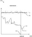
图1A是曲线图100,其示出了与当前主题的一些实施方式一致的与检测供应到蒸发器的加热元件的功率变化相关的特征。如上所述,微控制器可以被配置为当蒸发器处于ON状态并且在待机模式中处于待机温度120时周期性地测量加热元件的参数(出于简化讨论的目的而在本公开的其余部分中使用单数形式,但如上所述,可以使用多于一个参数)。所测量的参数可以可选地是在微控制器的控制下提供给加热元件以维持加热元件的恒定温度120的功率110。微控制器可以利用当加热元件处于待机温度时,恒定地需要一定已知量功率来维持待机温度的知识来预先编程。当维持加热元件的待机温度所需的功率超过预设值时,微控制器可将该差异记录为与用户在蒸发器上吸入相关(例如,抽吸130的开始)。这触发微控制器向电源发送信号,以将输入加热元件的功率增加到足以使可蒸发材料蒸发的温度。微控制器可以配置为比较在加热元件上存在温度变化时维持加热元件中的一定温度所需的功率并且仅当维持待机加热元件温度所需的功率超过预设值时增加到加热元件的功率以达到蒸发温度。该比较可以以数字方式执行,例如通过微控制器的使其执行操作(例如是接收指示施加为维持设定点温度的当前功率的输入并确定施加的当前功率是否指示抽吸已经开始)的编程,或者通过硬件执行,例如在满足某个预设条件时记录电压或其他信号的集成电路等。在一些示例中,当检测到抽吸时加热元件升高至的蒸发温度可以处于例如大约100摄氏度至大约300摄氏度的范围内。FIG. 1A is a
与当前主题的一些方面一致,可以通过检测功率函数而不是仅仅测量功率本身来建立对蒸发器的加热元件的控制。例如,表示功率变化的触发条件可以包括功率的一阶导数、功率的二阶导数或其某个组合。触发条件可以是对上述一个或多个参数的算法或数学关系。可以通过在蒸发器处于待机温度时检测提供给加热元件的功率的变化率(或一些其他算法或数学函数)来建立加热元件的控制。类似于蒸发器记录并试图维持加热元件的待机温度或蒸发温度的先前示例,微控制器可以设置为在蒸发器处于待机模式并处于待机温度时记录和读取供应给加热元件的功率的变化率。测量功率变化率可以提供更详细的用户吸入情况。通常,当用户开始在蒸发器上吸入时,穿过加热元件的空气流动迅速从零或接近零增加到某个最大量,然后随着用户停止抽吸而迅速减小,在用户停止抽吸时空气流急剧下降并变得接近零。空气流的变化可以与维持加热元件的温度所需的功率变化相关。当空气流增加时,来自加热元件的热量损失增加,并且维持待机温度所需的功率增加。这种功率变化可以遵循复杂的关系,使得可以通过监测输送功率的一个或多个导数而不仅仅是当前功率来实现对抽吸开始的改进检测。Consistent with some aspects of the current subject matter, control of the heating element of the evaporator can be established by detecting a function of power rather than just measuring power itself. For example, a trigger condition representing a change in power may include a first derivative of power, a second derivative of power, or some combination thereof. The triggering condition may be an algorithmic or mathematical relationship to one or more of the above parameters. Control of the heating element may be established by sensing the rate of change of power supplied to the heating element (or some other algorithm or mathematical function) while the evaporator is at standby temperature. Similar to the previous example where the evaporator records and attempts to maintain the standby or evaporating temperature of the heating element, the microcontroller can be set to record and read the rate of change of power supplied to the heating element while the evaporator is in standby mode and at standby temperature . Measuring the rate of power change can provide a more detailed picture of user inhalation. Typically, when a user starts to inhale on the vaporizer, the air flow across the heating element increases rapidly from zero or near zero to some maximum amount, then decreases rapidly as the user stops puffing, and the space The airflow drops sharply and becomes close to zero. Changes in air flow can be correlated to changes in power required to maintain the temperature of the heating element. As the air flow increases, the heat loss from the heating element increases and the power required to maintain the standby temperature increases. Such power changes may follow complex relationships such that improved detection of puff onset may be achieved by monitoring one or more derivatives of delivered power rather than just current power.
可以设置功率值,使得一旦超过维持给定待机温度的预设功率值,则微控制器就指示电源增加到加热元件的功率,使得加热元件达到蒸发温度。可替代地,可以应用如上所述的一个或多个(例如,一组)蒸发模式触发标准来确定抽吸是否已经开始以及是否需要增加蒸发温度,从而导致微控制器增加到加热元件的功率。在吸入结束时,空气流动下降并且从加热元件到流动空气的热损失因此减少,使得需要较少的功率来维持蒸发温度。一旦维持蒸发温度的功率下降到预设功率值,则微控制器就可以指示电源减少发送到加热元件的功率量,使得加热元件温度下降到待机温度。可替代地,可以应用如上所述的一个或多个(例如,一组)待机模式触发标准来确定抽吸是否已经结束以及是否需要降低蒸发温度,从而导致微控制器减少到加热元件的功率。The power level may be set such that once a preset level of power is exceeded to maintain a given standby temperature, the microcontroller instructs the power supply to increase power to the heating element so that the heating element reaches evaporation temperature. Alternatively, one or more (eg, a set) of evaporative mode trigger criteria as described above may be applied to determine whether puffing has started and whether the evaporative temperature needs to be increased, thereby causing the microcontroller to increase power to the heating element. At the end of the suction, the air flow drops and the heat loss from the heating element to the flowing air is thus reduced so that less power is required to maintain the evaporating temperature. Once the power to maintain the evaporating temperature drops to a preset power value, the microcontroller can instruct the power supply to reduce the amount of power sent to the heating element, causing the heating element temperature to drop to the standby temperature. Alternatively, one or more (eg, a set) of standby mode trigger criteria as described above may be applied to determine whether puffing has ended and the evaporation temperature needs to be lowered, thereby causing the microcontroller to reduce power to the heating element.
换句话说,在当前主题的功率输送监测实施方式中,微控制器能够在加热元件处于待机温度的情况下检测加热元件温度的变化并且相应地调节供应的功率以匹配设定点待机温度。一旦维持待机温度所需的功率变化显著变化(如通过实际功率值、所传递功率的一阶导数和/或所传递功率的二阶导数的某种组合匹配一种或多种蒸发模式触发标准(例如,由于用户在蒸发器上吸入)进行测量),微控制器确定正在发生抽吸并进入抽吸状态并增加到加热元件的功率,直到加热元件处于蒸发温度。在加热元件处于蒸发温度的情况下,微控制器仍能够检测加热元件温度的变化并相应地调节供应的功率以匹配设定点蒸发温度。一旦维持蒸发温度所需的功率变化显著变化(如通过实际功率值、所传递功率的一阶导数和/或所传递功率的二阶导数的某种组合匹配一种或多种(例如一组)待机模式触发标准(例如,由于用户在蒸发器上吸入)进行测量),则微控制器确定不再发生抽吸,如下面参考图2更详细地讨论。In other words, in the power delivery monitoring implementation of the present subject matter, the microcontroller is able to detect changes in the heating element temperature if the heating element is at standby temperature and adjust the supplied power accordingly to match the set point standby temperature. Once the power required to maintain standby temperature changes significantly (e.g., by some combination of actual power value, first derivative of delivered power, and/or second derivative of delivered power matching one or more evaporative mode trigger criteria ( For example, due to the user taking a puff on the vaporizer (taking a measurement), the microcontroller determines that puffing is occurring and enters puffing and increases power to the heating element until the heating element is at evaporating temperature. With the heating element at evaporating temperature, the microcontroller is still able to detect changes in the heating element temperature and adjust the power supplied accordingly to match the set point evaporating temperature. Once the power required to maintain the evaporating temperature varies significantly (such as by some combination of actual power value, first derivative of delivered power, and/or second derivative of delivered power matching one or more (e.g. a set) Standby mode triggers a criterion (measured, for example, due to a user puffing on the vaporizer) and the microcontroller determines that puffing is no longer occurring, as discussed in more detail below with reference to FIG. 2 .
与当前主题的一些方面一致,并且如图1B的曲线图150所示,可以基于维持提供给加热元件的恒定或接近恒定的功率水平170并检测温度160的变化来控制热量和加热时间。在这种情况下,恒定功率170被输送到加热元件并且监测加热元件温度160(或者,可替代地,温度随空气流动变化而变化的某个其他部件的温度)的变化。微控制器可以监测(例如,连续地,每隔几秒,以一些其他周期性等)加热元件的温度160,以确定是否需要改变蒸发器的状态。可替代地,可以监测温度函数,例如温度变化、温度的一阶和/或二阶导数。当经过加热元件的空气流动量由于用户吸入而增加时,加热元件的温度降低。一旦在没有显著空气流动量时的温度与存在吸入和在加热元件上方存在空气流动时的温度之间的温度差超过预设温度差(例如,抽吸启动130),则微控制器指示电源增加加热元件的功率以达到蒸发温度。随着电源继续向加热元件提供恒定的蒸发功率水平,当加热元件处于蒸发温度时,微控制器继续测量加热元件的温度(或温度函数)。由于加热元件上的空气流动变化,蒸发温度可能略微波动。一旦可被认为是用于蒸发的参考温度值(当蒸发期间在加热元件上几乎没有流动时)和所测量的蒸发温度之间的温度变化可以忽略不计,则微控制器可以向电源发信号以降低供应到加热元件的功率,使得实现待机温度。Consistent with aspects of the current subject matter, and as shown in
换句话说,在当前主题的温度监测实施方式中,微控制器在蒸发器处于待机模式的情况下维持对加热元件的恒定功率输送水平并且能够检测加热元件温度的变化。当实际温度、温度的一阶导数和/或温度的二阶导数的某种组合与一个或多个蒸发模式触发标准匹配时,微控制器确定正在发生抽吸并进入抽吸状态,其中到达加热元件的功率增加到足以使加热元件达到蒸发温度的第二功率水平。在加热元件处于蒸发温度的情况下,微控制器维持第二功率输送水平并且能够检测加热元件温度的变化。当实际温度、温度的一阶导数和/或温度的二阶导数的某种组合与一个或多个待机模式触发标准匹配时,微控制器确定没有发生抽吸并进入待机状态,其中到达加热元件的功率减小到足以使加热元件返回待机温度的第一功率水平。In other words, in the temperature monitoring implementation of the present subject matter, the microcontroller maintains a constant level of power delivery to the heating element while the evaporator is in standby mode and is able to detect changes in the temperature of the heating element. When some combination of actual temperature, first derivative of temperature, and/or second derivative of temperature matches one or more evaporative mode trigger criteria, the microcontroller determines that puffing is occurring and enters a puffing state, where heating is reached Power to the element is increased to a second power level sufficient to bring the heating element to the evaporation temperature. With the heating element at evaporating temperature, the microcontroller maintains the second power delivery level and is able to detect changes in the temperature of the heating element. When some combination of the actual temperature, the first derivative of temperature, and/or the second derivative of temperature matches one or more of the standby mode trigger criteria, the microcontroller determines that no draw is occurring and enters the standby state, where the heating element The power is reduced to a first power level sufficient to return the heating element to a standby temperature.
在当前主题的一些实施方式中,微控制器可以配置为在提供恒定功率的同时检测加热元件内的电阻。由于加热元件的电阻是温度的函数,因此电阻可以用作温度指示。类似地,可以测量加热元件的电阻变化(和/或一个或多个变化率的变化,例如电阻的一阶导数、二阶导数等)并且与蒸发器的不同状态(例如,待机模式或蒸发模式)相关。在当前主题的其他实施方式中,维持给定温度所需的电压或电流变化可以用作加热元件和/或暴露于空气流动的某个其他部件的功率或温度指示。可以监视这些参数和/或这些参数的一个或多个变化率(例如,一阶或二阶或其他导数)的变化,并与用于指示抽吸开始(因此需要切换到蒸发模式)和/或抽吸结束(因此需要切换到待机模式)的触发条件进行比较。In some implementations of the current subject matter, the microcontroller can be configured to detect resistance within the heating element while providing constant power. Since the resistance of a heating element is a function of temperature, the resistance can be used as an indication of temperature. Similarly, the change in resistance of the heating element (and/or change in one or more rates of change, such as the first derivative of resistance, the second derivative, etc.) ) related. In other embodiments of the current subject matter, the change in voltage or current required to maintain a given temperature may be used as an indication of power or temperature for a heating element and/or some other component exposed to air flow. Changes in these parameters and/or one or more rates of change (e.g., first or second or other derivatives) of these parameters can be monitored and used to indicate that puffing has started (and thus requires switching to vaping mode) and/or The trigger conditions for the end of puffing (and thus the need to switch to standby mode) are compared.
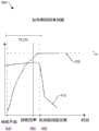
图2是表示在当前主题的功率输送监测实施方式中检测到吸入结束的曲线图200。一旦加热元件处于蒸发温度,则微控制器继续维持供应给加热元件的功率,以维持蒸发温度220(其可具有轻微的变化和/或波动),直到微控制器检测到维持加热元件的功率所需的功率量210降低到低于第二预设功率值,如图2的曲线图200所示。如同通过将一个或多个参数(可包括这些参数的一个或多个导数)与一个或多个蒸发模式触发标准相比较而检测到抽吸开始,可以通过将一个或多个参数(可以包括这些参数的一个或多个导数)与一个或多个待机模式触发标准相比较来检测抽吸结束。例如,加热元件所需功率的下降可以用作在加热元件处不需要这么多功率来维持蒸发温度的指示,这可能与加热元件上存在导致加热元件处的热损失的更少空气流动相关。当用户在蒸发器上完成或接近完成吸入(例如,抽吸230结束)时,在加热元件上产生更少空气流动。一旦维持蒸发温度所需的功率水平下降到第二预设功率水平,则微控制器可以指示电源将到达加热元件的功率降低到维持待机温度的水平。在当前主题的一些实施方式中,可以执行更复杂的分析,其不止涉及参数的当前值,例如所需的功率。例如,当某个组合(可能包括实际功率值、所输送功率的一阶导数和/或所输送功率的二阶导数中的一个或多个)匹配一个或多个待机模式触发标准(例如,由于用户在蒸发器上停止吸入)时,微控制器确定抽吸已经停止并进入待机状态,其中到达加热元件的功率减少直到加热元件处于待机温度。更复杂的分析(可能涉及所输送功率的一阶和/或二阶导数)可以更准确地表示对蒸发状态变化的检测。如上所述,可以对当前主题的恒定功率输送实施方式执行类似的分析(未示出)。FIG. 2 is a
在诸如加热元件达到其待机温度之前的冷却阶段期间进行后续抽吸(例如,在打开蒸发器之后但在加热元件达到待机温度之前开始吸入)或当微控制器使加热元件从待机温度加热到蒸发温度时的过早吸入停止的情况下,蒸发器的行为可以通过使用一个或多个蒸发模式触发标准和包括所监测参数的一个或多个导数的一个或多个蒸发模式触发标准来合意地改进。Subsequent puffing occurs during cooling phases such as before the heating element reaches its standby temperature (for example, after turning on the evaporator but before the heating element reaches the standby temperature) or when the microcontroller heats the heating element from the standby temperature to vaporization In the event of premature suction cessation at temperature, the behavior of the evaporator can be desirably improved by using one or more evaporative mode trigger criteria and one or more evaporative mode trigger criteria comprising one or more derivatives of the monitored parameters .
例如,参考图3,曲线图300示出了在冷却期间检测到吸入时的温度特征。在曲线图300中,最后一次抽吸的结束由点330表示、抽吸开始由点340表示,并且理论冷却曲线由曲线320表示。一旦功率需求下降低于某个预定值,则微控制器就检测到抽吸330的结束并且开始减少或完全关闭到达加热元件的功率,直到达到待机温度。微控制器可以测量由曲线310表示的冷却速率。在用户停止吸入的情况下,将装置送入到达加热元件的功率减少(或甚至关闭)的冷却阶段中,但是然后在再次达到待机温度之前启动后续吸入,微控制器仍然能够基于监测一个或多个导数以识别实际冷却型线比理论冷却曲线320更快来确定下一次抽吸已经开始。For example, referring to FIG. 3 ,
在另一个示例中,用户可以在打开蒸发器之后但在加热元件达到待机温度之前启动吸入。在这种情况下,微控制器可以用于检测加热元件的冷却速率。在冷却速率超过预编程值的情况下,微控制器引导电源以增加到达加热元件的功率,使得加热元件可以快速达到蒸发温度。In another example, the user may initiate the inhalation after turning on the vaporizer but before the heating element reaches a standby temperature. In this case, a microcontroller can be used to detect the cooling rate of the heating element. In the event that the cooling rate exceeds a preprogrammed value, the microcontroller directs the power supply to increase the power to the heating element so that the heating element can quickly reach the evaporation temperature.
如图4的曲线图400中所示(其中抽吸开始由点430表示、抽吸结束由点440表示,并且所检测的抽吸结束由点450表示),当加热元件正提升至蒸发温度时,用户可以在蒸发器上进行吸入的同时中途停止(440)。在那种情况下,经过加热元件的空气流动从足够高到触发和维持功率410以达到并保持蒸发温度(Tset 420)变为实际上没有空气流动通过加热元件。在一个示例中,微控制器可以允许加热元件达到蒸发温度(如果加热元件在空气流动停止之前没有达到该蒸发温度),并且类似于吸入并非突然停止时发生的情况(参见图2),一旦维持蒸发温度所需的功率量下降到预定阈值以下,则微控制器将斜坡减小发送到加热元件的功率。在其他示例中,微控制器可以用于感测功率被吸取以使加热元件达到蒸发温度或者维持蒸发温度的速率,以及立即降低功率以仅将蒸发温度保持在待机温度。在后一种情况下,在将功率降低到维持待机温度的水平之前,微控制器不必等待直到温度或功率的变化下降超过预定水平。As shown in
具有与本文描述的某些实施方式一致的特征的蒸发器可具有用于增加或减少到达加热元件的功率的快速响应时间。通常,达到待机温度的时间可少于几秒。一旦达到预定阈值功率或阈值温度变化,则达到蒸发温度的时间可以是快速的(例如,少于30秒、少于20秒、少于10秒、少于5秒、少于3秒、少于2秒、少于1秒等)A vaporizer having features consistent with certain embodiments described herein may have a fast response time for increasing or decreasing power to the heating element. Typically, the time to reach standby temperature can be less than a few seconds. Once a predetermined threshold power is reached or a threshold temperature change is reached, the time to vaporization temperature can be rapid (e.g., less than 30 seconds, less than 20 seconds, less than 10 seconds, less than 5 seconds, less than 3 seconds, less than 2 seconds, less than 1 second, etc.)
如上所述,具有与本文描述的某些实施方式一致的特征的蒸发器可包括ON/OFF开关。ON/OFF开关可以向微控制器提供蒸发器应该处于待机模式的清晰信号。在其他情况下,蒸发器可以包括加速度计,用于确定何时应该将装置置于待机模式。基于加速度计检测到的运动与参考加速度测量相比较,微控制器预测用户何时可能打算使用蒸发器。加速度计可以被编程为感测与使用蒸发器相关联的某些类型的运动,或者可以被编程用于检测指示用户打算使用蒸发器的某个运动或运动组合(例如,旋转蒸发器或其他有意运动)。As noted above, a vaporizer having features consistent with certain embodiments described herein may include an ON/OFF switch. The ON/OFF switch can provide a clear signal to the microcontroller that the evaporator should be in standby mode. In other cases, the vaporizer may include an accelerometer to determine when the device should be placed in standby mode. Based on the motion detected by the accelerometer compared to a reference acceleration measurement, the microcontroller predicts when the user may intend to use the vaporizer. The accelerometer may be programmed to sense certain types of motion associated with use of the vaporizer, or may be programmed to detect a certain motion or combination of motions that indicates the user intends to use the vaporizer (e.g., a rotary evaporator or other intentional sports).
由于使用加速度计来基于所感测的运动确定何时应将蒸发器置于待机模式可能难以将蒸发器的一般移动与希望开始使用蒸发器的用户相关联的移动区分开,因此将加速度计的存在与可替代感测机构耦合或利用可替代感测结构可能是有利的。在一些情况下,感测用户使用蒸发器的意图的额外模式可以借助电容感测、唇部感测、定时、触摸感测或其任何组合。Because using an accelerometer to determine when the vaporizer should be placed in standby mode based on sensed motion can make it difficult to distinguish general movement of the vaporizer from movement associated with a user wishing to start using the vaporizer, the presence of the accelerometer It may be advantageous to couple with or utilize alternative sensing mechanisms. In some cases, additional modes of sensing the user's intent to use the vaporizer may be by capacitive sensing, lip sensing, timing, touch sensing, or any combination thereof.
在当前主题的一些方面,电容感测机构可以结合加速度计或自身包括在蒸发器中。电容感测机构可设置在蒸发器的吸嘴中或周围。电容感测机构可用于确定用户的唇部是否正在接触吸嘴。与其他类型的皮肤接触相比,电容感测机构能够区分用户的唇部对电容感测机构的按压。当电容感测机构检测到用户唇部的存在时,其向微控制器发信号以打开蒸发器并且还将设备置于待机模式。在蒸发器包括ON/OFF开关的示例中,电容感测机构可用于辅助触发微控制器以使加热元件达到待机温度。在一些示例中,一旦电容感测机构感测到用户唇部的存在,则微控制器就可以向电源发信号以快速提供功率以加热加热元件,使得如上所述的那样采用蒸发器的风速相关感测能力。In some aspects of the current subject matter, the capacitive sensing mechanism can incorporate an accelerometer or be included in the vaporizer itself. A capacitive sensing mechanism may be provided in or around the suction nozzle of the vaporizer. A capacitive sensing mechanism may be used to determine whether the user's lips are touching the nozzle. The capacitive sensing mechanism is able to distinguish a press of the user's lips on the capacitive sensing mechanism compared to other types of skin contact. When the capacitive sensing mechanism detects the presence of the user's lips, it signals the microcontroller to turn on the vaporizer and also puts the device in standby mode. In examples where the vaporizer includes an ON/OFF switch, a capacitive sensing mechanism may be used to assist in triggering the microcontroller to bring the heating element to standby temperature. In some examples, once the capacitive sensing mechanism senses the presence of the user's lips, the microcontroller can signal the power supply to quickly provide power to heat the heating element such that the wind speed dependent evaporator is employed as described above. sensing capability.
在与当前主题的某些实施方式一致的一些方面中,当蒸发器切换到ON状态时,加热元件在待机温度下连续加热。通常,加热可以仅在蒸发器处于OFF状态时停止加热。在大多数情况下,维持待机温度所需的功率量仅为几毫瓦,并因此使蒸发器处于待机温度并不是对电源的大量消耗。In some aspects consistent with certain embodiments of the current subject matter, the heating element continues to heat at the standby temperature when the evaporator is switched to the ON state. Typically, the heating can only be turned off when the evaporator is OFF. In most cases, the amount of power required to maintain standby temperature is only a few milliwatts, and therefore keeping the evaporator at standby temperature is not a significant drain on power.
通常,加热元件可以是电阻加热元件,尽管空气流动冷却加热元件,但是电阻加热元件能够在加热元件上的空气流动与保持那个温度所需的温度和功率的变化之间产生风速相关性。加热元件可以横向于通过蒸发器的空气流放置,以便最准确地将空气流动(由于用户吸入)与维持预定温度所需的功率相关联。Typically, the heating element may be a resistive heating element which, although air flow cools the heating element, can create a wind speed dependency between the air flow over the heating element and the change in temperature and power required to maintain that temperature. The heating element can be placed transverse to the air flow through the evaporator to most accurately relate the air flow (due to user inhalation) to the power required to maintain a predetermined temperature.
图5示出了与当前主题的实施方式一致的示例性蒸发器装置500的特征。虽然蒸发器500通常包括盖子,图5示出了盖子被移除以便更好地显示蒸发器500的内部部件。蒸发器500包括设置在蒸发器500的近端端部上的吸嘴508。加热元件503也包含在蒸发器500内,其中加热元件503与微控制器505电接触。蒸发器500还包括电源504,该电源504与微控制器505和加热元件503均电连通。在该示例中,加热元件503围绕芯502缠绕,而在其他示例中,加热元件可以是适于加热可蒸发材料的其他构造。通常,加热元件503与芯502热接触或连通,并且芯502可以用含有活性化合物或物质的可蒸发流体饱和。在其他示例中,芯502仅需要与加热元件503接触,使得当加热元件503处于蒸发温度时,保持在芯502内的可蒸发材料可以蒸发。FIG. 5 illustrates features of an
蒸发器500还可包括用于保持可蒸发材料的贮存器501,如图5所示。在该示例中,芯502与贮存器501保持的液体流体连通,使得当可蒸发材料蒸发时,芯502能够通过毛细管作用和扩散将更多可蒸发材料吸取至芯502。在一些情况下,流体贮存器501可以从蒸发器500的其余部分移除,而在其他情况下,流体贮存器501可以永久地设置在蒸发器500内。在其他示例中,蒸发器可以彻底缺少包含流体的贮存器并且芯可以是一次性的并且预装有可蒸发材料。具有在所有可蒸发材料消失之后每次都可以更换的芯的优点是不存在来自每次先前蒸发剩余的残留物,这些残留物随着时间的推移可能变得有害。The
限定的气流路径507可以穿过蒸发器500定位以确保空气流横向流过加热元件503,以精确控制蒸发器500内的加热。A defined
当用户从蒸发器吸入时,空气流向用户的嘴,输送蒸发的材料或气雾剂。蒸发器通常包括用于引入空气流动的至少一个通风口。空气流动路径预定义在蒸发器内。通风口通常设置在蒸发器的远端端部处,使得当用户在蒸发器上进行吸取时,空气将进入装置并在加热元件上流动,用于提供将蒸发的材料输送给用户的方式并用于调节提供给加热元件的功率量。在一些示例中,所述至少一个通风口还可包括空气流动调节器或阀,用于控制可流到加热元件的最大空气流动量。在其他示例中,所述至少一个通风口可以进一步包括过滤器,以最小化环境颗粒进入蒸发器,从而减少外部颗粒随时间沉积在蒸发器的内表面上。When a user inhales from the vaporizer, air flows to the user's mouth, delivering vaporized material or aerosol. Evaporators typically include at least one vent for introducing air flow. Air flow paths are predefined within the evaporator. Vents are typically provided at the distal end of the vaporizer so that when the user draws on the vaporizer, air will enter the device and flow over the heating element, serving to provide a means of delivering vaporized material to the user and for Adjusts the amount of power supplied to the heating element. In some examples, the at least one vent may also include an air flow regulator or valve for controlling the maximum amount of air flow that may flow to the heating element. In other examples, the at least one vent may further include a filter to minimize entry of ambient particles into the evaporator, thereby reducing deposition of foreign particles on interior surfaces of the evaporator over time.
蒸发器可以包括通道,该通道有助于引导空气流动在加热元件上方通过装置,然后将所蒸发的材料通过吸嘴输送至用户。装置内的通道确保直接空气流动与加热元件接触。空气流动可以在加热元件上横向流动以提供空气流动和加热元件温度变化之间的精确相关性以及更有效的蒸发。The vaporizer may include channels that help direct the flow of air through the device over the heating element before delivering the vaporized material through the mouthpiece to the user. Channels within the unit ensure direct air flow in contact with the heating element. Air flow can flow across the heating element to provide precise correlation between air flow and heating element temperature variation and more efficient evaporation.
芯可以由能够吸收流体可蒸发材料的材料构成。通过自然毛细管作用和扩散,芯从含有湿润材料的贮存器中吸取流体。当可蒸发材料由于从加热元件传递的能量而蒸发并且从芯移除时,可以将更多可蒸发材料吸取至芯中直到可蒸发材料从贮存器耗尽。在一些实例中,芯由天然衍生纤维(例如棉、麻、竹子,椰子)或人造材料(例如二氧化硅纤维、陶瓷、金属网等)组成。在某些情况下,芯可仅供一次使用并且需要在所有可蒸发材料耗尽后更换。The wick may be constructed of a material capable of absorbing the fluid vaporizable material. Through natural capillary action and diffusion, the wick draws fluid from the reservoir containing the wetted material. As vaporizable material is vaporized and removed from the wick due to energy transferred from the heating element, more vaporizable material can be drawn into the wick until the vaporizable material is depleted from the reservoir. In some examples, the core is composed of naturally derived fibers (eg, cotton, hemp, bamboo, coconut) or man-made materials (eg, silica fibers, ceramics, metal mesh, etc.). In some cases, the wick may only be used once and needs to be replaced after all vaporizable material has been exhausted.
加热元件可以通过连接电路与微控制器和电源电连通。在一些情况下,蒸发器可以分成两件,其中两件中的每一件包括用于将加热元件电连接到微控制器和电源的电路的部分。当蒸发器的两个部分连接时,电路形成完整的电路并且可以将功率输送到加热元件。The heating element can be in electrical communication with the microcontroller and the power supply through the connecting circuit. In some cases, the vaporizer may be split into two pieces, where each of the two pieces includes portions of the circuitry for electrically connecting the heating element to the microcontroller and power supply. When the two parts of the evaporator are connected, the electrical circuit forms a complete circuit and power can be delivered to the heating element.
加热元件可以是电阻加热元件。加热元件可以是缠绕成具有固定直径的线圈的线材用于接收芯。加热元件可以由铂丝、钨丝或在高温下不降解或废气化的其它合适材料构成。加热元件通常能够在30摄氏度至500摄氏度的温度范围内进行加热。在蒸发器的一些示例中,用户可以从一系列蒸发温度设定蒸发温度。具有不同的蒸发温度可以是有用的,因为不同的可蒸发材料或组合物在不同温度下最佳地蒸发。可以在蒸发器上指示装置运行所处的蒸发温度(例如,不同颜色光显示)。The heating element may be a resistive heating element. The heating element may be a wire wound into a coil of fixed diameter for the receiving core. The heating element may be constructed of platinum wire, tungsten wire, or other suitable material that does not degrade or outgas at high temperatures. The heating element is generally capable of heating in the temperature range of 30 degrees Celsius to 500 degrees Celsius. In some examples of evaporators, the user can set the evaporating temperature from a range of evaporating temperatures. Having different evaporation temperatures can be useful because different vaporizable materials or compositions evaporate optimally at different temperatures. The evaporation temperature at which the device is operating can be indicated on the evaporator (eg, a different colored light display).
通常,电源可以是电池。电源可以是可充电的。蒸发器上的指示器可用于指示电池是否需要再充电以及电池何时充满电。Typically, the power source can be a battery. The power source may be rechargeable. Indicators on the vaporizer can be used to indicate if the battery needs to be recharged and when the battery is fully charged.
图6示出了与当前主题的实施方式一致的另外示例性蒸发器装置600的特征。蒸发器600可以具有第二线圈609,该第二线圈609与主加热元件603分开,如图6所示。与当前主题的实施方式一致,第二线圈609可以用作用于控制供应到加热元件603的功率的风速计。第二线圈609虽然能够加热,但不提供蒸发所需的热量;蒸发通过第一和主加热元件603提供。与蒸发器500类似,该蒸发器600通常具有三种状态:OFF状态,ON/待机状态以及ON/蒸发状态。类似于装置500,蒸发器600包括微控制器605,用于控制微控制器605、第一加热元件603、第二线圈609和电源604之间的通信、输入和输出。此外,蒸发器600可包括用于保持可蒸发流体的贮存器606、芯602以及吸嘴608。此外,存在通过蒸发器600的限定气流路径607,用于确保空气流横向流过第一加热元件603和第二线圈609用于精确控制蒸发器600内的加热。在一些情况下,空气横向流过第二线圈609可能比横向流过第一元件603更重要,原因在于在该可替代设计中,第二线圈609测量空气流动、由于空气流动导致的温度变化、以及空气流动变化率,用于控制输送到第一加热元件603的功率。如果空气流动在第二线圈609上以非横向路径行进,则检测到的流速可能存在不准确性,这可能导致确定对温度的影响的不准确性,最终可能导致输送到加热元件603的功率不足或过多。FIG. 6 illustrates features of an additional
与蒸发器500类似,当蒸发器600开启时,蒸发器600进入待机模式。微控制器604直接向加热元件603和第二线圈609发信号以加热到待机温度。在一些情况下,只有第二线圈609被加热到待机温度,而加热元件603保持在环境温度。类似地,待机温度是高于环境温度的温度,并且可以是例如50和70摄氏度范围内的任何温度。只要蒸发器600开启,微控制器604就保持加热元件603处的待机温度。微控制器604还周期性地测量维持第二线圈609处的待机温度所需的功率。Similar to the
当用户在吸嘴608上吸入时,第二线圈609上方的空气流动增加并降低第二线圈609的温度,使得需要更多功率来维持第二线圈609处的待机温度。一旦维持第二线圈609处的待机温度所需的功率超过预设功率值,则微控制器604假设用户正在吸嘴处吸入并开始加热加热元件603以使加热元件603的温度升高至蒸发温度。在加热元件603升温达蒸发温度并且加热元件603处保持蒸发温度的时间期间,第二线圈609的温度可以保持在待机温度。微控制器604继续向加热元件603发送足够功率用于维持蒸发温度,直到用于维持第二线圈609的待机温度的能量量返回到与第二线圈609上没有空气流动或具有最小空气流动相关的值。该情况对应用户在设备上结束抽吸或吸入。此时,微控制器604向电源发信号以停止向加热元件603发送功率并允许加热元件达到或待机温度或环境温度。When the user inhales on the
在一些情况下,用户可能在吸入中途突然停止吸入。在这种情况下,蒸发器可能处于两种可能的子状态。在第一种子状态下,加热元件没有达到蒸发温度,而在第二种子状态下,加热元件处于蒸发温度。在两者中,当维持第二线圈的待机温度所需的能量量下降到低于某个预设功率值时,微控制器向电源发信号停止向加热元件供电并允许加热元件冷却到或待机温度或环境温度。在其他示例中,当蒸发器从待机状态进入抽吸状态时,第二线圈的温度也可以与加热元件一起增加到蒸发温度。在后一种情况下,当维持蒸发温度的功率下降到低于预设功率值(这在几乎没有空气流过第二线圈时吸入结束的情况下发生)时,维持蒸发温度所需的功率将降低。In some cases, the user may suddenly stop the inhalation mid-inhalation. In this case, the evaporator can be in two possible sub-states. In the first seed state, the heating element has not reached the evaporation temperature, and in the second seed state, the heating element is at the evaporation temperature. In both, when the amount of energy required to maintain the standby temperature of the second coil drops below a certain preset power value, the microcontroller signals the power supply to stop power to the heating element and allow the heating element to cool down to or stand by temperature or ambient temperature. In other examples, when the evaporator enters the pumping state from the standby state, the temperature of the second coil may also be increased to the evaporating temperature together with the heating element. In the latter case, when the power to maintain the evaporating temperature drops below the preset power value (which occurs when the suction ends when almost no air flows through the second coil), the power required to maintain the evaporating temperature will decrease reduce.
在其他情况下,用户可在蒸发器处于冷却阶段时开始吸入。在这种情况下,一旦检测到加热元件温度或第二线圈温度的降低率大于预设值,则微控制器可以越过冷却阶段并切换回加热循环以将温度增大恢复到蒸发温度。In other cases, the user may initiate inhalation while the vaporizer is in the cooling phase. In this case, once it detects that the heating element temperature or the second coil temperature has decreased at a rate greater than a preset value, the microcontroller can bypass the cooling phase and switch back to the heating cycle to return the temperature increase back to the evaporation temperature.
图6中所示的蒸发器600除了增加第二线圈609之外与图5的蒸发器500类似地运行。蒸发器600的实施方式的优点在于:由于第二线圈在加热元件和可蒸发材料的下游,因此在大多数情况下,第二线圈不与可蒸发材料或由加热产生的蒸汽接触。因此,随着时间的推移,来自可蒸发材料的残留物将沉积在第二线圈线上并且不利地影响蒸发器的加热控制和功能性的可能性小得多。The
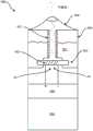
与当前主题的一些实施方式一致,蒸发器可构造成蒸发固体材料(例如松散叶类型样品)。适于蒸发固体样品的蒸发器可以具有烘箱而不是与加热元件热接触的芯或芯吸材料,该烘箱的示例在图7中以横截面图示出。蒸发器700在靠近(例如,几乎邻近或邻近)底部端部730处包括具有周围烘箱壳体713的内部烘箱701。盖子710在底部端部730处配合或以其他方式附接到外壳体714。吸嘴708在顶部端部720处配合或以其他方式附接到外壳体714。外壳体714的内部是结构壳体部件712。一个或多个内侧凹槽或通道709形成在结构壳体部件712的外侧壁和外壳体714的内侧壁之间并且沿着结构壳体部件712的外侧壁和外壳体714的内侧壁的长度延伸。内侧通道709从烘箱701延伸到吸嘴708,从而为待由用户吸入的可蒸发材料提供冷却通道。具有烘箱701的蒸发器700的变型可以适用于当前主题的一些方面。Consistent with some embodiments of the current subject matter, the vaporizer can be configured to vaporize solid material (eg, loose leaf-type samples). An evaporator suitable for evaporating solid samples may have an oven rather than a wick or wicking material in thermal contact with the heating element, an example of which is shown in cross-section in FIG. 7 . The
加热元件703与微控制器和电源电子通信。加热元件703可以是线材装置、加热板或任何其他合适的加热器,用于增加输入到烘箱701的能量以蒸发可蒸发材料。类似于具有芯构造的蒸发器,用于蒸发固体材料的蒸发器700可具有风速控制以调节加热。包含在其内的微控制器能够确定装置应处于哪种状态(例如,待机或蒸发状态)以及何时从一个状态切换到另一个状态然后返回。从一个状态到另一个状态的转换类似地基于相对于某个预设功率值周期性地测量提供给加热元件的功率(或其函数)变化。状态转换还可以基于相对于用于温度的预定方差周期性地测量温度(或其函数)波动,使得如果测量的温度偏差大于预设方差,则这表明用户正在蒸发器上进行抽吸;而如果偏差下降到或低于预设方差,则表明用户不再在蒸发器上进行吸入。在一些其他示例中,微控制器可以相对于预设变化率值周期性地对加热元件的温度或功率变化率进行采样,其中如果温度或功率变化率超过某个预设值,则用作用户在蒸发器上进行抽吸的指示;而如果温度或功率变化率下降到接近或处于零,则这用作用户停止蒸发器上的吸入的指示。The
包括与加热元件热接触的烘箱的设备(例如蒸发器700)可以配置成具有足够低的热质量,使得当用户在蒸发器上吸入时,这反而导致加热元件或表面处的温度下降。如果典型吸入对加热元件的温度影响很小或没有影响(例如,热质量太大),那么加热元件的风速调节的这种有利特征可能无法有效地用于调节加热元件的功率和加热。为了使加热元件具有低热质量,烘箱适于通过具有低热质量的加热元件有效地加热。加热元件的这些物理要求影响烘箱的尺寸和特征。A device including an oven in thermal contact with a heating element, such as
如前所述,本文描述的蒸发器可包括电容传感器,用于确定用户何时可开始在蒸发器上进行吸入。电容传感器可以位于吸嘴中和吸嘴周围,其中当用户将他或她的嘴压在电容传感器上时,微控制器指示电源向加热元件供应更多功率。电容传感器可以与风速确定用户何时开始在蒸发器上进行吸入结合使用。As previously mentioned, the vaporizers described herein may include a capacitive sensor for determining when a user may initiate inhalation on the vaporizer. Capacitive sensors may be located in and around the mouthpiece, wherein when the user presses his or her mouth against the capacitive sensor, the microcontroller instructs the power supply to supply more power to the heating element. A capacitive sensor can be used in conjunction with wind speed to determine when the user starts inhaling on the vaporizer.
在当前主题的一些实施方式中,风速确定可以由微控制器用作诊断工具来检查一个或多个其他传感器是否正确操作。例如,在具有压力传感器作为使得加热元件的加热基于检测到与用户吸取蒸发器的吸嘴一致的气流而被激活(例如,用户吮吸触发的激活)的主传感器的蒸发器中,与当前主题的实施方式一致的风速感测方法可以用作验证以确认压力传感器是否正常工作。例如,如果具有压力传感器的这种蒸发器的用户怀疑加热问题(例如,当在蒸发器上抽吸时,蒸发器不加热),则用户可以通过执行某些预定动作(例如,摇动装置、按下特定按钮或控制等)来打开诊断模式。一旦蒸发器进入诊断模式,用户就通过吸嘴进行吸入(可以通过来自装置的信号指示用户这样做(例如,控制灯打开或变成特定颜色),或者一旦用户将蒸发器进入诊断模式就可以被预先通知待采取的适当动作)。一旦进行抽吸,则微控制器确定压力传感器和风速感测方法是否都提供信号以引起加热元件的温度升高。如果正常运行,则压力传感器向微控制器发送信号指示压力传感器已检测到吸入。利用与本文描述的一些实施方式一致的风速感测方法,微控制器确定对于所监测的参数是否满足一个或多个诊断模式触发标准。所监测的参数(或多个参数)和触发标准类似于上面描述的那些。如果满足一个或多个诊断模式触发标准,则这用作用户在吸嘴上进行吸入的指示。如果压力传感器未发送信号,则这可以作为压力传感器未正常运行的指示。可以通过来自蒸发器的信号(例如,控制灯打开或变成特定警告颜色等)向用户发出警报。In some implementations of the current subject matter, the wind speed determination may be used by the microcontroller as a diagnostic tool to check that one or more other sensors are operating correctly. For example, in a vaporizer with a pressure sensor as the primary sensor such that the heating of the heating element is activated based on the detection of airflow coincident with the user sucking on the mouthpiece of the vaporizer (e.g. activation of the user sucking trigger), similar to the current subject matter A wind speed sensing method consistent with an embodiment may be used as a verification to confirm that the pressure sensor is functioning properly. For example, if a user of such a vaporizer with a pressure sensor suspects a heating problem (e.g., the vaporizer does not heat up when puffing on the vaporizer), the user can perform certain predetermined actions (e.g., shake the Press a specific button or control, etc.) to open diagnostic mode. Once the vaporizer enters diagnostic mode, the user inhales through the mouthpiece (the user may be instructed to do so by a signal from the device (for example, controlling a light to turn on or change to a specific color), or once the user puts the vaporizer into diagnostic mode advance notice of appropriate action to be taken). Once a puff is taken, the microcontroller determines whether both the pressure sensor and the wind speed sensing method are providing signals to cause an increase in the temperature of the heating element. If functioning properly, the pressure sensor sends a signal to the microcontroller indicating that the pressure sensor has detected an inhalation. Using wind speed sensing methods consistent with some embodiments described herein, the microcontroller determines whether one or more diagnostic mode trigger criteria are met for the monitored parameter. The monitored parameter (or parameters) and trigger criteria are similar to those described above. If one or more diagnostic mode trigger criteria are met, this serves as an indication that the user is inhaling on the mouthpiece. If the pressure sensor is not sending a signal, this can be an indication that the pressure sensor is not functioning properly. The user may be alerted by a signal from the vaporizer (for example, a control light turns on or changes to a specific warning color, etc.).
作为压力传感器用于用户吮吸触发激活的另一种方法,与当前主题的实施方式一致的风速感测方法可以用作压力传感器的备用。这可以通过监测加热元件的一个或多个参数并通过确定对于这些参数满足一个或多个蒸发模式触发标准来实现。可以基于预定义的时间表(例如,当蒸发器处于待机模式时每10、20或30秒)周期性地进行监测,一旦蒸发器处于待机模式则持续进行监测或者以另一个间隔进行监测。响应于确定对于这些参数满足一个或多个蒸发模式触发标准,控制器检查或测量加热元件的温度。可以在经过预定时间段之后获得和/或确定温度读数,以使加热元件有足够的时间达到蒸发温度。温度读数可以通过例如温度传感器或如上进一步所述测量加热元件的电阻来实现。如果加热元件处于适当的蒸发温度,则表明压力传感器正常运行并且感测到用户吮吸触发激活。然而,如果加热元件未处于适当的蒸发温度,则这可能是压力传感器未正常运行的指示。响应于这种确定,可以通过控制器启动备用加热操作来增加到达加热元件的功率输送,以将加热元件加热到蒸发温度。As another method for the pressure sensor to be used for user sucking trigger activation, the wind speed sensing method consistent with the embodiments of the current subject matter can be used as a backup for the pressure sensor. This may be accomplished by monitoring one or more parameters of the heating element and by determining that one or more vaporization mode trigger criteria are met for those parameters. Monitoring may be performed periodically based on a predefined schedule (eg, every 10, 20 or 30 seconds while the evaporator is in standby mode), continuously once the evaporator is in standby mode, or at another interval. In response to determining that one or more evaporative mode trigger criteria are met for these parameters, the controller checks or measures the temperature of the heating element. The temperature reading may be obtained and/or determined after a predetermined period of time has elapsed to allow sufficient time for the heating element to reach the evaporating temperature. Temperature readings may be achieved, for example, by a temperature sensor or by measuring the resistance of the heating element as described further above. If the heating element is at the proper evaporating temperature, the pressure sensor is functioning properly and the user sucking is sensed to activate the trigger. However, if the heating element is not at the proper evaporating temperature, this could be an indication that the pressure sensor is not functioning properly. In response to this determination, alternate heating operations may be initiated by the controller to increase power delivery to the heating element to heat the heating element to the evaporation temperature.
在当前主题的一些实施方式中,蒸发器可包括本体和吸嘴。这些装置中的任何一个可以配置成包括含有吸嘴和/或加热器和/或可蒸发材料源的料盒。控制器和/或电池可以单独地保持在与料盒匹配的本体内。可替代地,可以集成该装置,使得加热器与控制器和其他部件一起位于本体内。例如,在一些变型中,本体可以围绕加热元件、微控制器和电源。在一些变型中,蒸发器可包括用于从贮存器吸取出可蒸发材料的芯。蒸发器可包括至少一个通风口,用于在用户抽吸(通过吸嘴吸取)时将空气引入装置中以及加热元件和可蒸发材料上方。蒸发器可包括位于装置内的一个或多个通道,用于在加热元件和可蒸发材料上流转气流。In some embodiments of the current subject matter, a vaporizer can include a body and a suction nozzle. Any of these devices may be configured to include a cartridge containing a suction nozzle and/or a heater and/or a source of vaporizable material. The controller and/or battery may be held separately within a body that mates with the cartridge. Alternatively, the device can be integrated so that the heater is located within the body along with the controller and other components. For example, in some variations, the body may surround the heating element, microcontroller and power supply. In some variations, the vaporizer may include a wick for drawing vaporizable material from the reservoir. The vaporizer may comprise at least one vent for introducing air into the device and above the heating element and vaporizable material when the user takes a puff (drawing through the mouthpiece). The vaporizer may include one or more channels within the device for directing air flow over the heating element and vaporizable material.
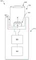
图8示出了与当前主题的实施方式一致的额外示例性蒸发器装置800的特征。蒸发器800包括配置成接收可移除料盒820的本体810。本体810包括与微控制器805电连通的电源804。料盒820包括设置在料盒820的近端端部上的吸嘴808。加热元件803包含在料盒820内。限定气流路径807位于蒸发器800的料盒820中,用于确保空气流横向流过加热元件803用于精确控制蒸发器800内的加热。在这种实施方式中,空气入口822和空气出口(吸嘴808)都位于料盒820本身上,从而通过消除料盒820和本体810之间的气流连接和连通而显著地简化了料盒接口,因此仅需要料盒820和装置本体810之间的电接触。FIG. 8 illustrates features of an additional
图9示出了控制器的特征,该控制器可以适于调节与当前主题的实施方式一致的蒸发器装置内的热量。方框图900包括微控制器910,该微控制器910耦合(例如,连通、电连通或以其他方式连接)到加热元件(例如上述加热元件503,603,609,703,803)。如上所述,微控制器910监测加热元件的功率和/或温度函数。输入可以是期望的一个或多个温度输入930(例如,期望的蒸发温度),其由用户确定和输入并且如上所述由微控制器910使用。除了用户输入,期望的温度输入可以预先建立并输入到微控制器910。Figure 9 illustrates features of a controller that may be adapted to regulate heat within an evaporator device consistent with embodiments of the present subject matter. Block diagram 900 includes
图9与当前主题的实施方式一致的示例实现了从电源920(可以是蒸发器500,600,700,800的一部分)到加热元件503,603,609,703,803的电能输送。电源920还向微控制器910提供功率。Figure 9 is an example consistent with an embodiment of the present subject matter enabling power delivery from a power source 920 (which may be part of a
参照图10,过程流程图1000示出了方法的特征,其可以可选地包括以下中的一些或全部。在1010处,监测蒸发器的加热元件的参数。在1020处,确定对于参数满足一个或多个蒸发模式触发标准。蒸发模式触发标准包括参数的值和/或参数的导数的值中的一个或多个,指示用户在吸嘴上吸入以使气流通过加热元件。在1030处,响应于与一个或多个蒸发模式触发标准相关的确定,增加向加热元件的功率输送以使加热元件加热到蒸发温度。Referring to FIG. 10 , process flow diagram 1000 illustrates features of a method, which may optionally include some or all of the following. At 1010, parameters of a heating element of the evaporator are monitored. At 1020, it is determined that one or more evaporative mode trigger criteria are met for the parameter. The vaporization mode triggering criteria include one or more of a value of a parameter and/or a value of a derivative of a parameter, instructing the user to inhale on the mouthpiece to cause airflow through the heating element. At 1030, in response to a determination related to the one or more vaporization mode trigger criteria, power delivery to the heating element is increased to heat the heating element to the vaporization temperature.
参照图11,过程流程图1100示出了方法的特征,其可以可选地包括以下中的一些或全部。在1110处,可以接收来自蒸发器的用户的诊断模式指示。在1120,确定是否从蒸发器的压力传感器接收到信号。该信号指示压力传感器检测到用户在蒸发器的吸嘴上吸入以引起空气气流。在1130处,确定对于所监测的参数是否满足一个或多个诊断模式触发标准。如果满足,这表示用户在蒸发器的吸嘴上吸入。在1150,响应于确定操作向用户提供操作指示。例如,如果没有从压力传感器接收到信号并且如果对于所监测参数满足一个或多个诊断模式触发标准,则操作指示器可以指示操作失败。如果从压力传感器接收到信号,则这是压力信号正常运行的指示,并且可以向用户提供相关联的操作指示(例如,成功操作)。例如,操作指示器可以是控制灯的形式。Referring to FIG. 11 , process flow diagram 1100 illustrates features of a method, which may optionally include some or all of the following. At 1110, a diagnostic mode indication can be received from a user of the vaporizer. At 1120, it is determined whether a signal is received from a pressure sensor of the evaporator. This signal indicates that the pressure sensor detects that the user draws on the suction nozzle of the vaporizer to cause air flow. At 1130, it is determined whether one or more diagnostic mode trigger criteria are met for the monitored parameter. If satisfied, this indicates that the user is inhaling on the mouthpiece of the vaporizer. At 1150, an operation instruction is provided to the user in response to the determination operation. For example, the operational indicator may indicate operational failure if no signal is received from the pressure sensor and if one or more diagnostic mode trigger criteria are met for the monitored parameter. If a signal is received from the pressure sensor, this is an indication that the pressure signal is functioning properly and an associated operational indication (eg, successful operation) may be provided to the user. For example, an operational indicator may be in the form of a control light.
提供以下对示例实施方式的描述以说明可能是当前主题的一部分的各种特征。它们不旨在进行限制。The following description of example implementations is provided to illustrate various features that may be a part of the current subject matter. They are not intended to be limiting.
本文描述了用于借助通过监测维持或达到电阻加热器的温度所需的功率(例如,电流、电压或两者的某种组合)来感测电阻加热器上的流动来调节蒸发器内的加热的蒸发器设备(例如,装置、系统和部件)以及方法,或者这些设备可以在所施加功率保持在预定水平时监测电阻加热器的温度。例如,本文描述的设备和方法可以将为实现目标温度而施加的绝对功率与阈值功率值进行比较,和/或可以比较施加预定功率时的温度变化率。特别地,本文所述的蒸发设备和方法可以通过监测施加到加热元件的功率使用蒸发可蒸发材料的相同加热元件(例如,电阻加热器)作为流动传感器(例如,作为风速流动传感器)。This article describes a method for regulating heating within an evaporator by monitoring the power (e.g., current, voltage, or some combination of the two) required to maintain or reach the temperature of a resistive heater by sensing flow over a resistive heater. The evaporator devices (eg, devices, systems, and components) and methods of the present invention, or these devices can monitor the temperature of a resistive heater while the applied power is maintained at a predetermined level. For example, the devices and methods described herein may compare the absolute power applied to achieve a target temperature to a threshold power value, and/or may compare the rate of temperature change when a predetermined power is applied. In particular, the vaporization apparatus and methods described herein can use the same heating element (eg, a resistive heater) that vaporizes vaporizable material as a flow sensor (eg, as an air velocity flow sensor) by monitoring the power applied to the heating element.
例如,蒸发器可包括一个或多个加热元件(电阻加热器),其用于蒸发可蒸发材料并且还可以例如使用控制器和/或其他监测电路直接监测,以监测温度和加热加热元件所需的施加功率并将施加的功率和温度与预定值(阈值)进行比较。以这种方式,如本文将更详细描述的,当用户通过蒸发器的吸嘴吸入以使空气流过加热元件时,该设备可以检测加热元件上方的气流。For example, the vaporizer may include one or more heating elements (resistive heaters) that are used to vaporize the vaporizable material and may also be directly monitored, for example, using a controller and/or other monitoring circuitry to monitor the temperature and heating elements required. The applied power and the applied power and temperature are compared with predetermined values (thresholds). In this way, as will be described in more detail herein, the device can detect airflow over the heating element when a user inhales through the vaporizer's suction nozzle to flow air over the heating element.
例如,可以自动地(通过感测用户持有装置,和/或通过感测唇部或手接触装置(包括吸嘴))或手动地(例如,通过切换控制,例如开关、按钮等)而将设备置于“开启”状态(例如,打开)。在开启状态下,设备可以将加热元件(电阻加热器)保持在预定温度,在此称为基础温度或待机温度(例如,介于40-80℃之间、介于45-75℃之间、介于50-70℃之间等)。然后,该设备可以监测所施加的功率以检测所施加的功率何时达到或超过指示来自用户的跨越加热元件吸取空气(吸入)的气流的阈值。可替代地,可以施加预定功率(基础或待机功率水平)并监测温度以确定温度何时达到或低于阈值触发温度(可以是例如介于40℃和70℃之间),从而指示用户通过设备吸取空气。如本文所使用的,术语“功率”可以指电流、电压或电流和电压的组合(例如,当前时间电压)。For example, the device can be activated automatically (by sensing that the user is holding the device, and/or by sensing lips or hands touching the device (including the nozzle)) or manually (for example, by switching controls, such as switches, buttons, etc.). The device is placed in an "on" state (eg, turned on). In the on state, the device can maintain the heating element (resistive heater) at a predetermined temperature, referred to herein as the base or standby temperature (for example, between 40-80°C, between 45-75°C, Between 50-70°C, etc.). The device may then monitor the applied power to detect when the applied power reaches or exceeds a threshold indicative of an air flow from the user drawing air across the heating element (aspiration). Alternatively, a predetermined power (base or standby power level) may be applied and the temperature monitored to determine when the temperature reaches or falls below a threshold trigger temperature (which may be, for example, between 40°C and 70°C), thereby instructing the user to pass the device suck in the air. As used herein, the term "power" may refer to current, voltage, or a combination of current and voltage (eg, current time voltage).
通常,本文描述的设备和方法被配置为与蒸发器一起操作,其中加热元件(例如,电阻加热器)的温度可以确定并用作温度反馈控制的一部分(例如,PID(比例-积分-微分)控制器)。例如,控制器(例如,PCB上的微控制器)可以配置成监测加热器的温度,使得可蒸发材料被加热到规定温度。规定温度可以是用户提供的输入。温度传感器可以与微控制器通信,以向微控制器提供输入温度用于进行温度调节。温度传感器可以是热敏电阻、热电偶、温度计或任何其他温度传感器。可替代地或另外地,加热元件(电阻加热器)的温度可以由加热元件的电阻确定(不需要单独额外的温度传感器)。在本文所述的任何变型中,可以使用加热元件(例如,电阻加热器)的电阻来代替温度,或者在其中电阻加热器的电阻是电阻加热器的温度的特征体现的变型中,可以将电阻值转换为温度。例如,可以基于电阻加热器的电特性(例如,电阻加热器(例如,“电阻加热元件”或“蒸发元件”)的电阻温度系数或TCR)来估计目标电阻。如本领域所公知的,加热器的电阻可用于计算加热器的温度(特别是与参考电阻值相比)。因此,加热元件的电阻可以是到控制器的输入,以控制温度并确定流动。在一些情况下,电阻可以由控制器(例如,微控制器)基于来自具有至少一个已知电阻的电阻器的电路的测量来确定,例如惠斯通电桥。可替代地,可以利用与加热元件接触的电阻分压器和具有已知且基本恒定的电阻的电阻器来测量加热元件的电阻。可以通过放大器放大加热元件的电阻的测量值(或与已知电阻的差值)。放大器可以是标准运算放大器或仪表放大器。放大的信号可以基本上没有噪声。在一些情况下,可以确定加热元件和电容器之间的分压器的充电时间以计算加热元件的电阻。在某些情况下,微控制器必须在电阻测量期间停用加热元件。加热元件的电阻可以是加热元件的温度的函数,使得温度可以直接由电阻测量值确定。直接从加热元件电阻测量而不是从额外温度传感器确定温度可以产生更准确的测量,因为消除了温度传感器和加热元件之间的未知接触热阻。另外,温度测量可以被直接确定并因此更快,而没有与加热元件和与加热元件接触的温度传感器之间达到平衡相关的时间滞后。In general, the devices and methods described herein are configured to operate with evaporators where the temperature of a heating element (e.g., a resistive heater) can be determined and used as part of a temperature feedback control (e.g., a PID (proportional-integral-derivative) control device). For example, a controller (eg, a microcontroller on a PCB) may be configured to monitor the temperature of the heater so that the vaporizable material is heated to a prescribed temperature. The prescribed temperature may be an input provided by a user. The temperature sensor can communicate with the microcontroller to provide an input temperature to the microcontroller for temperature regulation. The temperature sensor can be a thermistor, thermocouple, thermometer or any other temperature sensor. Alternatively or additionally, the temperature of the heating element (resistance heater) may be determined by the resistance of the heating element (no separate additional temperature sensor required). In any of the variations described herein, the resistance of the heating element (e.g., a resistive heater) can be used instead of temperature, or in variations in which the resistance of the resistive heater is characterized by the temperature of the resistive heater, the resistance Values are converted to temperatures. For example, the target resistance may be estimated based on an electrical characteristic of the resistive heater (eg, the temperature coefficient of resistance or TCR of the resistive heater (eg, "resistive heating element" or "evaporating element")). As is known in the art, the resistance of a heater can be used to calculate the temperature of the heater (especially compared to a reference resistance value). Thus, the resistance of the heating element can be an input to a controller to control temperature and determine flow. In some cases, the resistance may be determined by a controller (eg, a microcontroller) based on measurements from a circuit having at least one resistor of known resistance, such as a Wheatstone bridge. Alternatively, the resistance of the heating element may be measured using a resistive divider in contact with the heating element and a resistor having a known and substantially constant resistance. The measured value of the resistance of the heating element (or the difference from the known resistance) can be amplified by an amplifier. The amplifier can be a standard op amp or an instrumentation amplifier. The amplified signal can be substantially free of noise. In some cases, the charging time of a voltage divider between the heating element and capacitor can be determined to calculate the resistance of the heating element. In some cases, the microcontroller must deactivate the heating element during the resistance measurement. The resistance of the heating element can be a function of the temperature of the heating element such that the temperature can be determined directly from the resistance measurement. Determining the temperature directly from the heating element resistance measurement rather than from an additional temperature sensor results in a more accurate measurement because the unknown contact thermal resistance between the temperature sensor and the heating element is eliminated. In addition, the temperature measurement can be determined directly and thus faster, without the time lag associated with reaching equilibrium between the heating element and the temperature sensor in contact with the heating element.
在本文所述的设备和方法中,可以在装置开启时检测吸取(吸入),并且通过检测何时维持基础温度(或当电阻值用于控制加热器温度时,电阻加热器的基础电阻)所需的功率增加至高于功率阈值,例如,大于稳态功率的2%(例如,大于5%,大于7%,大于10%,大于12%,大于15%等)而将加热元件维持在基础温度。可以为加热器设备预先确定用于基本功率的稳态功率,或者可以根据设备的操作或其某种组合来凭经验确定稳态功率。等效地,当加热元件保持在固定(基础)功率并且温度降低至阈值以下,例如降低稳态温度的1%或更多(例如,降低2%或更多,5%或更多,7%或更多,10%或更多,15%或更多等)时,可以检测到来自设备的吸嘴的吸取。如上所述,在某些情况下,电阻(当电阻与加热元件的温度成比例时)可以代替温度更简单地使用,使得当保持在基本功率时的加热元件的电阻降低到阈值以下时可以确定吸取。In the devices and methods described herein, suction (suction) can be detected when the device is turned on and determined by detecting when the base temperature (or the base resistance of a resistive heater when the resistance value is used to control heater temperature) is maintained. The required power is increased above a power threshold, e.g., greater than 2% of steady state power (e.g., greater than 5%, greater than 7%, greater than 10%, greater than 12%, greater than 15%, etc.) to maintain the heating element at base temperature . The steady state power for the base power may be predetermined for the heater device, or the steady state power may be empirically determined from the operation of the device, or some combination thereof. Equivalently, when the heating element is held at a fixed (base) power and the temperature drops below a threshold, e.g., by 1% or more of the steady state temperature (e.g., by 2% or more, 5% or more, 7% or more, 10% or more, 15% or more, etc.), suction from the device's suction nozzle can be detected. As mentioned above, in some cases resistance (when the resistance is proportional to the temperature of the heating element) can be used more simply instead of temperature, so that when the resistance of the heating element while held at base power falls below a threshold, it can be determined that draw.
通常,本文所述的蒸发器可包括本体和吸嘴。这些装置中的任何一个可以配置成包括包含吸嘴和/或电阻加热器和/或可蒸发材料源的料盒;控制器和/或电池可以单独地保持在与料盒匹配的本体内。可替代地,该设备可以集成在一起使得电阻加热器与控制器和其他部件一起位于本体内。例如,在一些变型中,本体可以包围:加热元件、微控制器和电源。在一些变型中,蒸发器可包括芯用于从贮存器吸出可蒸发材料。蒸发器可包括至少一个通风口,用于在用户抽吸(通过吸嘴吸取)时将空气引入装置中以及引导通过加热元件和可蒸发材料上方。蒸发器可以包括位于装置内的一个或多个通道用于在加热元件(例如,电阻加热器,例如电阻线圈)和可蒸发材料上流转气流。Generally, the vaporizers described herein may include a body and a suction nozzle. Any of these devices may be configured to include a cartridge containing a suction nozzle and/or a resistive heater and/or a source of vaporizable material; the controller and/or battery may be held separately within a body that mates with the cartridge. Alternatively, the device may be integrated so that the resistive heater is located within the body along with the controller and other components. For example, in some variations, the body may enclose: a heating element, a microcontroller and a power supply. In some variations, the vaporizer may include a wick for drawing vaporizable material from the reservoir. The vaporizer may comprise at least one vent for introducing air into the device and over the heating element and vaporizable material when the user takes a puff (drawing through the mouthpiece). The vaporizer may include one or more channels within the device for circulating a gas flow over a heating element (eg, a resistive heater, such as a resistive coil) and vaporizable material.
本文描述的蒸发器中的任何一个可具有不同的状态。例如,蒸发器可以处于OFF状态,直到用户手动或自动打开(通过将蒸发器接触唇部等)。用户可以通过按下ON/OFF开关手动打开装置。一旦蒸发设备处于ON状态,则控制器(例如,设备的本体内的微控制器)可以控制电源以将功率输送到加热元件以达到基础(也称为“待机”)温度并监测所施加的功率(例如,电流,电压等),其中待机温度远低于目标可蒸发材料的蒸发温度。可替代地,设备可以配置成在加热器上施加基础(例如,待机)功率并监测加热器的温度(或电阻)。Any of the evaporators described herein may have different states. For example, the vaporizer may be in an OFF state until manually or automatically turned on by the user (by touching the vaporizer to a lip, etc.). The user can manually turn on the unit by pressing the ON/OFF switch. Once the evaporative device is ON, a controller (e.g. a microcontroller within the body of the device) can control the power supply to deliver power to the heating element to reach a base (aka "standby") temperature and monitor the power applied (eg, current, voltage, etc.), where the standby temperature is much lower than the vaporization temperature of the target vaporizable material. Alternatively, the device may be configured to apply basal (eg, standby) power to the heater and monitor the temperature (or resistance) of the heater.
例如,微控制器可以被编程为通过改变发送到加热元件的功率量来保持基础温度。当用户在蒸发设备的吸嘴上进行抽吸时,空气被吸取到蒸发器并经过加热元件,其中空气将加热元件冷却一定量。处理器可以检测到这种冷却,并且可以增加所施加的功率(通过控制回路)来维持温度或者可以在功率保持恒定时检测温度下降(例如,或者电阻的对应变化)。在第一种情况下,当控制设备以维持基础温度时,为补偿加热元件和待机温度之间的温度偏差而汲取的功率满足或超过预定功率值(阈值),控制器可以识别这可以是用户进行抽吸并且启动(触发)施加到加热元件的功率增加,使得加热元件可以达到目标蒸发温度(通常介于100和400℃之间)。当维持蒸发温度所需的功率量下降到低于第二预设功率水平时,微控制器可以启动冷却模式。For example, a microcontroller can be programmed to maintain a base temperature by varying the amount of power sent to the heating element. When a user draws on the suction nozzle of the evaporating device, air is drawn up the evaporator and past the heating element, where the air cools the heating element by a certain amount. The processor can detect this cooling and can increase the power applied (via the control loop) to maintain temperature or can detect a drop in temperature (eg, or a corresponding change in resistance) while power remains constant. In the first case, when controlling the device to maintain the base temperature, the power drawn to compensate for the temperature deviation between the heating element and the standby temperature meets or exceeds a predetermined power value (threshold), the controller can recognize that this may be a user Pumping is applied and an increase in power to the heating element is initiated (triggered) so that the heating element can reach a target evaporation temperature (typically between 100 and 400°C). When the amount of power required to maintain the evaporating temperature drops below a second preset power level, the microcontroller may activate the cooling mode.
在这些变型中的任何一个中,可以基于值(功率、温度、电阻等)的变化率或加速度(一阶或二阶导数)而不是值的大小来确定吸取。特别地,通过将所施加的能量、电阻或温度的变化率(或加速度)与阈值进行比较,即使将温度从待机温度升高到蒸发温度时,也可以检测到何时吸取。例如,如果温度从在待机模式中的静止(待机)温度升高到蒸发或加热模式下的蒸发温度时的温度变化率比阈值速率值慢,那么用户可以继续在吸嘴上吸取;可替代地,如果变化率大于或等于阈值,则用户可能已经停止抽吸,并且控制器可以将温度返回到待机值。一旦设备处于蒸发模式的温度(蒸发温度),则控制器可以将维持蒸发温度所施加的能量与第二阈值进行比较,以确定用户何时停止抽吸,使得可以将温度返回到待机水平(例如,当将温度保持在蒸发温度所需的功率下降到阈值以下时)。In any of these variations, pick-up may be determined based on the rate of change of a value (power, temperature, resistance, etc.) or acceleration (first or second derivative) rather than the magnitude of the value. In particular, by comparing the rate of change (or acceleration) of applied energy, resistance, or temperature to a threshold, it is possible to detect when suction occurs even when increasing the temperature from standby to evaporating. For example, if the rate of temperature change from a resting (standby) temperature in standby mode to an evaporating temperature in evaporating or heating mode is slower than the threshold rate value, the user may continue to draw on the nozzle; alternatively , if the rate of change is greater than or equal to the threshold, the user may have stopped puffing and the controller may return the temperature to the standby value. Once the device is at the temperature of the vaporization mode (vapor temperature), the controller can compare the energy applied to maintain the vapor temperature with a second threshold to determine when the user stops puffing so that the temperature can be returned to the standby level (e.g. , when the power required to maintain the temperature at the evaporating temperature falls below the threshold).
例如,控制器可以被编程为检测维持加热元件处的温度所需的功率的变化率或加热元件的温度变化率,并将该变化与用户何时进行抽吸与否相关联。当用户进行抽吸时,维持待机温度所需的功率变化率或温度变化率增加。当微控制器检测到高于阈值的变化率时,其可以开始使加热元件达到蒸发温度。当维持蒸发温度所需的功率或温度的变化率下降到阈值以下时,微控制器可以将其与用户停止抽吸相关联并使加热元件温度回到待机温度。For example, the controller may be programmed to detect the rate of change in power required to maintain the temperature at the heating element or the rate of temperature change of the heating element and correlate that change with when the user is taking a puff or not. As the user takes a puff, the rate of change of power or rate of temperature change required to maintain the standby temperature increases. When the microcontroller detects a rate of change above a threshold, it can start bringing the heating element up to evaporation temperature. When the power required to maintain the evaporative temperature or the rate of change in temperature drops below a threshold, the microcontroller can correlate this with the user stopping the puff and bring the heating element temperature back to the standby temperature.
如上所述,在保持供应给加热元件的功率恒定的同时允许待机温度波动时,待机状态下的流动可替代地由设备检测到。一旦用户在蒸发装置上进行抽吸,则加热元件处的温度将下降并且当温度下降到低于阈值温度值时,控制器可以识别出用户正在抽吸并且触发加热到蒸发温度。As mentioned above, flow in the standby state may alternatively be detected by the device while keeping the power supplied to the heating element constant while allowing the standby temperature to fluctuate. Once the user takes a puff on the vaping device, the temperature at the heating element will drop and when the temperature drops below a threshold temperature value, the controller can recognize that the user is puffing and trigger heating to the vaping temperature.
在本发明的一些方面,蒸发设备可包括第二线圈,其用于使通过第二线圈上方的空气流动与温度变化或功率变化相关联。在该变型中,第二线圈可以放置在主加热线圈的下游并远离产生的湿气和/或蒸汽。第二线圈与微控制器和电源电连通。In some aspects of the invention, the evaporative device may include a second coil for correlating air flow over the second coil with a change in temperature or a change in power. In this variant, the secondary coil may be placed downstream of the primary heating coil and away from the moisture and/or steam generated. The second coil is in electrical communication with the microcontroller and a power source.
本文描述的设备可包括用于蒸发固体材料的烘箱。烘箱与加热元件热接触。以与具有芯的蒸发设备中的加热元件相同的方式控制加热元件温度。The apparatus described herein may include an oven for evaporating solid materials. The oven is in thermal contact with the heating element. The heating element temperature is controlled in the same way as the heating element in an evaporating device with a wick.
本文描述的设备可包括电容感测,用于控制或帮助控制蒸发加热机构。电容感测可以被配置为感测用户的唇部是否与吸嘴接触,这可以指示用户使用蒸发设备的意图。The devices described herein may include capacitive sensing for controlling or assisting in controlling the evaporative heating mechanism. Capacitive sensing may be configured to sense whether the user's lips are in contact with the mouthpiece, which may indicate the user's intent to use the vaporizing device.
本文描述的设备可包括加速度计。加速度计可以被编程为感测某些类型的运动,这些运动可以单独使用或者与风速辅助控制结合使用以调节蒸发设备内的加热。Devices described herein may include accelerometers. Accelerometers can be programmed to sense certain types of motion which can be used alone or in combination with wind speed assist control to regulate heating within the evaporative device.
因此,本文描述了控制蒸发器的方法,包括控制具有电阻加热器的蒸发设备的方法,所述电阻加热器配置成蒸发可蒸发材料并检测用户在蒸发设备上吸入,所述方法包括:在蒸发装置开启时,通过向电阻加热器施加功率而维持电阻加热器上的基础温度;监测维持电阻加热器的基础温度所需的功率;当维持基础温度所需的功率达到或超过第一功率阈值时,将电阻加热器的温度从基础温度升高到蒸发温度;以及使与电阻加热器连通的可蒸发材料蒸发。Accordingly, described herein are methods of controlling a vaporizer, including methods of controlling a vaporization device having a resistive heater configured to vaporize a vaporizable material and detecting inhalation by a user on the vaporization device, the method comprising: maintaining a basal temperature on the resistive heater by applying power to the resistive heater when the device is turned on; monitoring the power required to maintain the basal temperature of the resistive heater; when the power required to maintain the basal temperature meets or exceeds a first power threshold , raising the temperature of the resistive heater from the base temperature to the evaporation temperature; and vaporizing the vaporizable material in communication with the resistive heater.
这些方法中的任何一种还可以包括一旦维持蒸发温度所需的功率降低到或低于第二功率阈值时,就将温度降低回基础温度。Any of these methods may also include reducing the temperature back to the base temperature once the power required to maintain the evaporating temperature decreases to or below a second power threshold.
通常,监测所需的功率可以包括监测施加到电阻加热器的电压或电流中的一个。升高温度可以包括增加施加到电阻加热器的功率。In general, monitoring the required power may include monitoring one of the voltage or current applied to the resistive heater. Raising the temperature may include increasing the power applied to the resistive heater.
这些方法中的任何一种还可以包括当施加为将电阻加热器的温度升高到蒸发温度的功率的变化率降低到变化率阈值以下时将温度降低到基础温度。Any of these methods may also include reducing the temperature to the base temperature when the rate of change of the power applied to raise the temperature of the resistive heater to the evaporation temperature decreases below a rate of change threshold.
本文描述的方法中的任何一种可以包括打开蒸发设备上的功率。例如,这些方法可以包括通过电容感测用户触摸装置自动打开到蒸发设备的功率、当加速度计装置检测到蒸发设备的移动时自动打开到蒸发设备的功率等。Any of the methods described herein can include turning on power on the evaporation device. For example, these methods may include automatically turning on power to the vaporizing device by capacitively sensing a user touching the device, automatically turning on power to the vaporizing device when the accelerometer device detects movement of the vaporizing device, and the like.
监测维持基础温度所需的功率可以包括监测功率的变化率。Monitoring the power required to maintain the basal temperature may include monitoring a rate of change of power.
本文还描述了这样设备,其中相同的结构(加热器)既用于蒸发材料又用于检测流动(例如,加热器被配置为风速计)。例如,这里描述的蒸发设备配置成使用配置成蒸发可蒸发材料的电阻加热器检测用户在蒸发设备上的吸入,该设备包括:电阻加热器;吸嘴;控制器,其配置为将电阻加热器维持在基础温度并且监视维持电阻加热器的基础温度所需的功率,控制器还配置为当维持基础温度所需的功率满足或超过第一功率阈值时将电阻加热器的温度增加至蒸发温度;可蒸发材料源,其与电阻加热器连通;以及电源,其配置为向控制器和电阻加热元件供电。Also described herein are devices where the same structure (heater) is used for both evaporating material and detecting flow (eg, the heater is configured as an anemometer). For example, the vaporization devices described herein are configured to detect inhalation by a user on the vaporization device using a resistive heater configured to vaporize a vaporizable material, the device comprising: a resistive heater; a mouthpiece; a controller configured to turn the resistive heater maintaining at a base temperature and monitoring power required to maintain the base temperature of the resistive heater, the controller is further configured to increase the temperature of the resistive heater to the evaporation temperature when the power required to maintain the base temperature meets or exceeds a first power threshold; a source of vaporizable material in communication with the resistive heater; and a power source configured to power the controller and the resistive heating element.
控制器还可以被配置为一旦维持蒸发温度所需的功率降低到或低于第二功率阈值,就将温度降低回到基础温度。控制器还可以被配置为监测施加到电阻加热器的电压或电流中的一个。The controller may also be configured to decrease the temperature back to the base temperature once the power required to maintain the evaporating temperature decreases to or below a second power threshold. The controller can also be configured to monitor one of the voltage or current applied to the resistive heater.
如上所述,这些设备中的任何一个可以包括ON/OFF开关,其中控制器被配置为当ON/OFF开关接通时保持基础温度。该设备可以包括电容传感器,该电容传感器被配置为当用户接触蒸发设备时自动打开蒸发装置并保持基础温度。可替代地或另外地,该设备可以包括加速度计,该加速度计被配置为在蒸发设备移动时自动打开蒸发设备并保持基础温度。As noted above, any of these devices may include an ON/OFF switch, wherein the controller is configured to maintain a base temperature when the ON/OFF switch is on. The device may include a capacitive sensor configured to automatically turn on the vaporizing device and maintain a base temperature when a user touches the vaporizing device. Alternatively or additionally, the device may include an accelerometer configured to automatically turn on the evaporating device and maintain the base temperature when the evaporating device is moved.
在具有基础温度的变型中,基础温度可以例如介于约50至70摄氏度之间。在具有基本功率的变型中,可以选择基本功率,使得加热器在基本功率下的正常运行温度在该温度范围之间。In variations with a base temperature, the base temperature may, for example, be between about 50 and 70 degrees Celsius. In the variant with base power, the base power can be selected such that the normal operating temperature of the heater at base power is between this temperature range.
电阻加热器可以是电阻线圈(例如,围绕芯或烘箱缠绕的线圈)。因此,在一些变型中,设备包括与电阻加热器热连通的芯。A resistive heater may be a resistive coil (eg, a coil wound around a core or oven). Thus, in some variations, the device includes a wick in thermal communication with the resistive heater.
通常,可蒸发材料源可包括用于保持可蒸发材料的贮存器(例如,罐等)。In general, the source of vaporizable material may include a reservoir (eg, tank, etc.) for holding the vaporizable material.
蒸发设备可包括用于蒸发固体可蒸发材料的烘箱,其中烘箱与电阻加热器热连通。The evaporation apparatus may include an oven for evaporating the solid vaporizable material, wherein the oven is in thermal communication with the resistive heater.
如上所述,本文描述的设备中的任何一个可包括耦合到(可重复使用的)基部的可移除料盒。例如,电阻加热器、吸嘴和可蒸发材料源可以是与电源和控制器电接触的可移除料盒的一部分。As mentioned above, any of the devices described herein may include a removable cartridge coupled to the (reusable) base. For example, the resistive heater, suction nozzle and source of vaporizable material may be part of a removable cartridge that is in electrical contact with the power source and controller.
本文还描述了这样的设备,其中第二电阻加热器与蒸发材料的电阻加热器协调使用。第二电阻加热器可以不直接接触可蒸发材料,但是可以定位在蒸发材料的(第一)电阻加热器的流动路径中。例如,蒸发设备可包括:吸嘴;空气路径,其从吸嘴延伸;空气路径中的第一电阻加热器;第二电阻加热器,其配置为测量通过空气路径的空气流动,其中第二电阻加热器位于空气路径内;控制器,其配置为维持第二电阻加热器上的基础温度并且当维持第二电阻加热器的基础温度所需的功率超过第一功率阈值时将第一电阻加热器的温度升高至蒸发温度;可蒸发材料源,其与第一电阻加热器连通;以及电源。Also described herein is an apparatus wherein a second resistive heater is used in coordination with the resistive heater for evaporating the material. The second resistive heater may not be in direct contact with the vaporizable material, but may be positioned in the flow path of the (first) resistive heater evaporating the material. For example, the vaporization device may include: a suction nozzle; an air path extending from the suction nozzle; a first resistive heater in the air path; a second resistive heater configured to measure air flow through the air path, wherein the second resistive heater a heater located within the air path; a controller configured to maintain a base temperature on the second resistive heater and turn the first resistive heater on when power required to maintain the base temperature of the second resistive heater exceeds a first power threshold a temperature raised to an evaporating temperature; a source of evaporable material in communication with the first resistive heater; and a power source.
第二电阻加热器可以是线圈(例如,电阻线圈)或其他线材元件。蒸发设备可包括与线圈连通的芯。源可包括用于保持可蒸发材料的贮存器。The second resistive heater may be a coil (eg, a resistive coil) or other wire element. The evaporation device may include a wick in communication with the coil. The source may include a reservoir for holding vaporizable material.
第一电阻加热器(例如,配置为蒸发材料)可以位于第二电阻加热器和吸嘴之间。可替代地,第二电阻加热器(其未配置为蒸发材料)可以位于第一电阻加热器和吸嘴之间。A first resistive heater (eg, configured to evaporate material) may be located between the second resistive heater and the suction nozzle. Alternatively, a second resistive heater (which is not configured to evaporate material) may be located between the first resistive heater and the suction nozzle.
如上所述,该设备可包括可移除料盒,该可移除料盒包括吸嘴和其他部件。例如,吸嘴、空气路径、第一电阻加热器、第二电阻加热器和可蒸发材料源都可以是与电源和控制器电接触的可移除料盒的一部分。As mentioned above, the device may include a removable cartridge including the nozzle and other components. For example, the suction nozzle, air path, first resistive heater, second resistive heater and source of vaporizable material may all be part of a removable cartridge in electrical contact with the power source and controller.
当特征或元件在本文中被称为“位于另一特征或元件上”时,它可以直接位于另一特征或元件上,或者也可以存在中间特征和/或元件。相反,当特征或元件被称为“直接位于另一特征或元件上”时,不存在中间特征或元件。还应该理解,当一个特征或元件被称为“连接”、“附接”或“耦合/耦接”到另一个特征或元件时,其可以直接连接、附接或耦合/耦接至另一个特征或元件或可以存在中间特征或元件。相反,当特征或元件被称为“直接连接”、“直接附接”或“直接耦合/耦接”至另一特征或元件时,不存在中间特征或元件。尽管关于一个实施例进行了描述或示出,但是如此描述或示出的特征和元件可以应用于其它实施例。本领域技术人员还将理解,对与另一特征“相邻”设置的结构或特征的引用可具有与相邻特征叠覆或位于相邻特征之下的部分。When a feature or element is referred to herein as being "on" another feature or element, it can be directly on the other feature or element, or intervening features and/or elements may also be present. In contrast, when a feature or element is referred to as being "directly on" another feature or element, there are no intervening features or elements present. It will also be understood that when a feature or element is referred to as being "connected," "attached," or "coupled/coupled" to another feature or element, it can be directly connected, attached, or coupled/coupled to the other feature or element. Features or elements or intermediate features or elements may be present. In contrast, when a feature or element is referred to as being "directly connected," "directly attached" or "directly coupled/coupled" to another feature or element, there are no intervening features or elements present. Although described or illustrated with respect to one embodiment, the features and elements so described or illustrated may apply to other embodiments. Those skilled in the art will also understand that references to a structure or feature that is disposed "adjacent" another feature may have portions that overlap or underlie the adjacent feature.
这里使用的术语仅用于描述特定实施例目的,而不是对本发明进行限制。例如,除非上下文另有明确说明否则如本文所用的单数形式“一”,“一个”和“该”旨在也包括复数形式。将进一步理解,当在本说明书中使用时,术语“包括”和/或“包含”指定所述特征、步骤、操作、元件和/或器件存在,但不排除存在或添加一个或多个其他特征、步骤、操作、元件,器件和/或其组。如本文所使用的,术语“和/或”包括相关所列项目中的一个或多个的任何和所有组合并且可以缩写为“/”。The terminology used herein is for the purpose of describing particular embodiments only and is not intended to be limiting of the invention. For example, as used herein, the singular forms "a", "an" and "the" are intended to include the plural forms as well, unless the context clearly dictates otherwise. It will be further understood that when used in this specification, the terms "comprising" and/or "comprising" specify the presence of stated features, steps, operations, elements and/or devices, but do not exclude the presence or addition of one or more other features , steps, operations, elements, devices and/or groups thereof. As used herein, the term "and/or" includes any and all combinations of one or more of the associated listed items and may be abbreviated as "/".
在以上描述和权利要求中,可能出现之后是元件或特征的联合列表的诸如“…中的至少一个”或“…中的一个或多个”的短语。术语“和/或”也可以出现在两个或更多个元件或特征的列表中。除非另外隐含地或明确地与其使用的上下文相矛盾,否则这样的短语旨在单独地表示任何列出的元件或特征,或者与任何其他列举的元件或特征组合的任何列举元件或特征。例如,短语“A和B中的至少一个”、“A和B中的一个或多个”和“A和/或B”各自旨在表示“单独A、单独B或A和B一起”。类似的解释也适用于包括三个或更多项目的列表。例如,短语“A,B和C中的至少一个”、“A,B和C中的一个或多个”、和“A,B和/或C”各自旨在表示“单独A、单独B、单独的C、A和B一起、A和C一起、B和C一起、或A和B和C一起”。在权利要求上或在权利要求中使用术语“基于”意指“至少部分地基于”,使得未被记载的特征或元件也是允许的。In the above description and claims, phrases such as "at least one of" or "one or more" followed by a joint listing of elements or features may appear. The term "and/or" may also appear in a list of two or more elements or features. Such phrases are intended to mean any listed element or feature alone or in combination with any other listed element or feature, unless otherwise implicitly or explicitly contradicted by the context of its use. For example, the phrases "at least one of A and B", "one or more of A and B", and "A and/or B" are each intended to mean "A alone, B alone, or A and B together." A similar explanation applies to lists of three or more items. For example, the phrases "at least one of A, B, and C," "one or more of A, B, and C," and "A, B, and/or C" are each intended to mean "A alone, B alone, C alone, A and B together, A and C together, B and C together, or A and B and C together". Use of the term "based on" on or in a claim means "based at least in part on" such that non-recited features or elements are also permissible.
为了易于描述,本文可以使用例如“下”,“下方”、“上”、“上方”等的空间相对术语来描述一个元件或特征与如图所示的其它元件或特征的关系。应当理解,除了图中所示的定向之外,空间相对术语旨在包括使用或操作中的装置的不同定向。例如,如果图中的装置被反转,则被描述为在其他元件或特征“下”或“下方”的元件将被“定向”在其他元件或特征“上方”。因此,示例性术语“在...之下”可以包括上方和下方两个定向。装置可以以其他方式定向(旋转90度或以其他定向),并且相应地解释本文使用的空间相对描述符。类似地,除非另有明确说明,否则本文使用术语“向上”、“向下”、“竖直”、“水平”等仅用于解释的目的。For ease of description, spatially relative terms such as "below", "below", "upper", "above" etc. may be used herein to describe the relationship of one element or feature to other elements or features as shown in the figures. It will be understood that the spatially relative terms are intended to encompass different orientations of the device in use or operation in addition to the orientation depicted in the figures. For example, if the device in the figures is turned over, elements described as "below" or "beneath" other elements or features would then be oriented "above" the other elements or features. Thus, the exemplary term "below" can encompass both an orientation of above and below. The device may be otherwise oriented (rotated 90 degrees or at other orientations) and the spatially relative descriptors used herein interpreted accordingly. Similarly, the terms "upward," "downward," "vertical," "horizontal," etc. are used herein for purposes of explanation only, unless expressly stated otherwise.
尽管这里可以使用术语“第一”和“第二”来描述各种特征/元件(包括步骤),除非上下文另有说明,否则这些特征/元件不应受这些术语的限制。这些术语可用于将一个特征/元件与另一个特征/元件区分开。因此,下面讨论的第一特征/元件可以被称为第二特征/元件,并且类似地,下面讨论的第二特征/元件可以被称为第一特征/元件而不脱离本发明的教导。Although the terms "first" and "second" may be used herein to describe various features/elements (including steps), these features/elements should not be limited by these terms unless the context dictates otherwise. These terms are used to distinguish one feature/element from another feature/element. Thus, a first feature/element discussed below could be termed a second feature/element, and, similarly, a second feature/element discussed below could be termed a first feature/element without departing from the teachings of the present invention.
如本说明书和权利要求书中所使用的,包括如实施例中所使用的并且除非另有明确说明,否则所有数字可以被读作以“约”或“近似”一词开头,即使该术语没有明确出现。当描述幅度和/或位置以指示所描述的值和/或位置在合理的预期值和/或位置范围内时,可以使用短语“约”或“近似”。例如,数值可以是所述值(或值的范围)+/-0.1%、所述值(或值的范围)+/-1%、所述值(或值的范围)+/-2%、所述值(或值的范围)+/-5%,所述值(或值的范围)+/-10%等。除非上下文另有说明,否则此处给出的任何数值还应理解为包括大约或近似该值。例如,如果公开了值“10”,则还公开了“约10”。本文引用的任何数值范围旨在包括其中包含的所有子范围。还应理解,如本领域技术人员适当理解的,当公开某值时,则“小于或等于该值”、“大于或等于该值”和值之间的可能范围也被公开。例如,如果公开值“X”,则还公开了“小于或等于X”以及“大于或等于X”(例如,其中X是数值)。还应理解,在整个申请中,数据以多种不同格式提供,并且该数据表示终止点和起始点以及数据点的任何组合的范围。例如,如果公开了特定数据点“10”和特定数据点“15”,则应理解为大于、大于或等于、小于、小于或等于、并且等于10和15以及在10和15之间也被认为是公开的。还应该理解,还公开了两个特定单元之间的每个单元。例如,如果公开了10和15,则还公开了11,12,13和14。As used in the specification and claims, including in the examples, and unless expressly stated otherwise, all numbers may be read as beginning with the word "about" or "approximately," even if the term is not clearly appear. The phrase "about" or "approximately" may be used when describing magnitude and/or location to indicate that the described value and/or location is within a reasonable expected range of value and/or location. For example, a numerical value may be +/- 0.1% of the stated value (or range of values), +/- 1% of the stated value (or range of values), +/- 2% of the stated value (or range of values), The stated value (or range of values) +/- 5%, the stated value (or range of values) +/- 10%, etc. Unless the context dictates otherwise, any numerical value given herein should also be understood to include approximately or approximately that value. For example, if the value "10" is disclosed, then "about 10" is also disclosed. Any numerical range recited herein is intended to include all subranges subsumed therein. It should also be understood that when a value is disclosed, "less than or equal to the value", "greater than or equal to the value" and possible ranges between values are also disclosed, as properly understood by those skilled in the art. For example, if the value "X" is disclosed, then "less than or equal to X" and "greater than or equal to X" are also disclosed (eg, where X is a numerical value). It should also be understood that throughout the application, data is provided in a number of different formats and that the data represents ending and starting points and ranges for any combination of data points. For example, if a specific data point "10" and a specific data point "15" are disclosed, it is understood that greater than, greater than or equal to, less than, less than or equal to, and equal to 10 and 15 and between 10 and 15 are also considered is public. It is also understood that every unit between two specific units is also disclosed. For example, if 10 and 15 are disclosed, then 11, 12, 13 and 14 are also disclosed.
尽管上文描述了各种说明性实施方式,但可在不脱离权利要求所述的本发明的范围的情况下对各种实施方式进行任何改变。例如,在替代实施方式中可以经常改变执行各种所描述的方法步骤的顺序,并且在其他替代实施方式中,可以完全跳过一个或多个方法步骤。各种装置和系统实现的可选特征可以包括在一些实施方式中而不包括在其他实施方式中。由于本发明的范围在权利要求中进行阐述,因此,提供前述描述主要是出于示例性目的并且不应被解释为限制本发明的范围。While various illustrative embodiments have been described above, any changes may be made to the various embodiments without departing from the scope of the invention as described in the claims. For example, the order of performing various described method steps may often be varied in alternative embodiments, and in other alternative embodiments, one or more method steps may be skipped entirely. Various apparatus and system-implemented optional features may be included in some embodiments but not in others. Since the scope of the invention is set forth in the claims, the foregoing description is provided for illustrative purposes only and should not be construed as limiting the scope of the invention.
本文描述的主题的一个或多个方面或特征可以在数字电子电路、集成电路、专门设计专用集成电路(ASIC)、现场可编程门阵列(FPGA)计算机硬件、固件、软件、和/或其组合中实现。这些各种方面或特征可以包括在可编程系统上可执行和/或可解释的一个或多个计算机程序中的实施方式,该可编程系统包括至少一个可编程处理器,其可以是专用的或通用的、耦合为从存储系统、至少一个输入装置和至少一个输出装置接收数据并将数据和指令发送到存储系统、至少一个输入装置和至少一个输出装置。可编程系统或计算系统可包括客户端和服务器。客户端和服务器通常彼此远离并且通常通过通信网络进行交互。客户端和服务器的关系借助在相应计算机上运行并且彼此具有客户端-服务器关系的计算机程序而产生。One or more aspects or features of the subject matter described herein can be implemented in digital electronic circuits, integrated circuits, application-specific integrated circuits (ASICs), field-programmable gate array (FPGA) computer hardware, firmware, software, and/or combinations thereof realized in. These various aspects or features may include an embodiment in one or more computer programs executable and/or interpretable on a programmable system comprising at least one programmable processor, which may be a dedicated or Commonly, coupled to receive data from and transmit data and instructions to the storage system, at least one input device, and at least one output device. A programmable system or computing system can include clients and servers. Clients and servers are typically remote from each other and typically interact through a communication network. The relationship of client and server arises by virtue of computer programs running on the respective computers and having a client-server relationship to each other.
也可以称为程序、软件、软件应用、应用、器件或代码的这些计算机程序包括用于可编程处理器的机器指令,并且可以用高级过程语言、面向对象编程语言、函数编程语言、逻辑编程语言和/或汇编/机器语言实现。如这里所使用的,术语“机器可读介质”指的是用于将机器指令和/或数据提供到可编程处理器的任何计算机程序产品、设备和/或装置,例如磁盘、光盘、存储器和可编程逻辑装置(PLD),包括接收作为机器可读信号的机器指令的机器可读介质。术语“机器可读信号”指的是用于向可编程处理器提供机器指令和/或数据的任何信号。机器可读介质可以非暂时地存储这样的机器指令,例如非瞬态固态存储器或磁性硬盘驱动器或任何等同的存储介质。机器可读介质可以替代地或附加地以瞬态方式存储这样的机器指令,例如处理器缓存或与一个或多个物理处理器核相关联的其他随机存取存储器。These computer programs, which may also be referred to as programs, software, software applications, applications, devices, or code, include machine instructions for a programmable processor and may be written in a high-level procedural language, object-oriented programming language, functional programming language, logic programming language and/or assembly/machine language implementation. As used herein, the term "machine-readable medium" refers to any computer program product, device and/or means for providing machine instructions and/or data to a programmable processor, such as a magnetic disk, optical disk, memory and A programmable logic device (PLD) includes a machine-readable medium that receives machine instructions as machine-readable signals. The term "machine-readable signal" refers to any signal used to provide machine instructions and/or data to a programmable processor. A machine-readable medium may store such machine instructions non-transitory, such as a non-transitory solid-state memory or a magnetic hard drive or any equivalent storage medium. A machine-readable medium may alternatively or additionally store such machine instructions in a transitory manner, such as a processor cache or other random access memory associated with one or more physical processor cores.
为了提供与用户的交互,可以在具有显示装置(例如用于向用户显示信息的阴极射线管(CRT)或液晶显示器(LCD)或发光二极管(LED)监视器)以及用户可以向计算机提供输入的键盘和指示装置(例如鼠标或跟踪球)的计算机上实现本文描述的主题的一个或多个方面或特征。其他类型的装置也可用于提供与用户的交互。例如,提供给用户的反馈可以是任何形式的传感反馈,例如视觉反馈、听觉反馈或触觉反馈;并且可以以任何形式接收来自用户的输入,包括但不限于声学、语音或触觉输入。其他可能的输入装置包括但不限于触摸屏或其他触敏装置,例如单点或多点电阻或电容式触控板、语音识别硬件和软件、光学扫描仪、光学指针、数字图像捕获装置和相关联的解释软件等。In order to provide interaction with the user, the computer may be provided on a computer having a display device such as a cathode ray tube (CRT) or a liquid crystal display (LCD) or a light emitting diode (LED) monitor for displaying information to the user, and the user may provide input to the computer. One or more aspects or features of the subject matter described herein are implemented on a computer with a keyboard and pointing device, such as a mouse or trackball. Other types of devices may also be used to provide interaction with the user. For example, the feedback provided to the user may be any form of sensory feedback, such as visual feedback, auditory feedback, or tactile feedback; and the input from the user may be received in any form, including but not limited to acoustic, voice, or tactile input. Other possible input devices include, but are not limited to, touch screens or other touch-sensitive devices such as single or multi-point resistive or capacitive touchpads, voice recognition hardware and software, optical scanners, optical pointers, digital image capture devices and associated interpretation software, etc.
本文包括的示例和说明通过说明而非限制的方式示出了可以实践主题的具体实施方式。如上所述,可以利用并从中导出其他实施方式,使得可以在不脱离本公开的范围的情况下进行结构和逻辑替换和改变。本发明主题的此类实施方式在本文中可单独地或共同地由术语“发明”来指代,如果事实上公开了不止一个发明,则不意图将本申请的范围自愿地限制于任何单个发明或发明构思而仅仅是为了方便。因此,尽管本文已说明和描述了特定实施方式,但经计算以实现相同目的的任何设置可替代所展示的特定实施方式。本公开旨在涵盖各种实现的任何和所有修改或变化。在阅读以上描述后,上述实施方式的组合以及本文未具体描述的其他实施方式对于本领域技术人员而言将是显而易见的。The examples and descriptions included herein show specific embodiments of the subject matter in which the subject matter may be practiced by way of illustration and not limitation. As described above, other embodiments may be utilized and derived therefrom, such that structural and logical substitutions and changes may be made without departing from the scope of this disclosure. Such embodiments of the inventive subject matter may be referred to herein, individually or collectively, by the term "invention", and if there is in fact more than one invention disclosed, it is not intended that the scope of this application be constrained voluntarily to any single invention. or inventive concept but for convenience only. Therefore, while specific embodiments have been illustrated and described herein, any arrangement that is calculated to achieve the same purpose may be substituted for the specific embodiments shown. This disclosure is intended to cover any and all adaptations or variations of various implementations. Combinations of the above embodiments, and other embodiments not specifically described herein, will be apparent to those of skill in the art upon reading the above description.
Claims (10)
Applications Claiming Priority (4)
| Application Number | Priority Date | Filing Date | Title |
|---|---|---|---|
| US201662371463P | 2016-08-05 | 2016-08-05 | |
| US62/371,463 | 2016-08-05 | ||
| CN201780061818.6ACN109789285B (en) | 2016-08-05 | 2017-08-04 | Wind speed auxiliary control of evaporator |
| PCT/US2017/045616WO2018027189A2 (en) | 2016-08-05 | 2017-08-04 | Anemometric-assisted control of a vaporizer |
Related Parent Applications (1)
| Application Number | Title | Priority Date | Filing Date |
|---|---|---|---|
| CN201780061818.6ADivisionCN109789285B (en) | 2016-08-05 | 2017-08-04 | Wind speed auxiliary control of evaporator |
Publications (2)
| Publication Number | Publication Date |
|---|---|
| CN115736391Atrue CN115736391A (en) | 2023-03-07 |
| CN115736391B CN115736391B (en) | 2025-06-20 |
Family
ID=59593248
Family Applications (4)
| Application Number | Title | Priority Date | Filing Date |
|---|---|---|---|
| CN202510729056.9APendingCN120531201A (en) | 2016-08-05 | 2017-08-04 | Evaporator air speed auxiliary control |
| CN202110940559.2AActiveCN113662278B (en) | 2016-08-05 | 2017-08-04 | Evaporator wind speed auxiliary control |
| CN201780061818.6AActiveCN109789285B (en) | 2016-08-05 | 2017-08-04 | Wind speed auxiliary control of evaporator |
| CN202211723182.6AActiveCN115736391B (en) | 2016-08-05 | 2017-08-04 | Evaporator wind speed auxiliary control |
Family Applications Before (3)
| Application Number | Title | Priority Date | Filing Date |
|---|---|---|---|
| CN202510729056.9APendingCN120531201A (en) | 2016-08-05 | 2017-08-04 | Evaporator air speed auxiliary control |
| CN202110940559.2AActiveCN113662278B (en) | 2016-08-05 | 2017-08-04 | Evaporator wind speed auxiliary control |
| CN201780061818.6AActiveCN109789285B (en) | 2016-08-05 | 2017-08-04 | Wind speed auxiliary control of evaporator |
Country Status (8)
| Country | Link |
|---|---|
| US (3) | US10729179B2 (en) |
| EP (2) | EP4233954A3 (en) |
| CN (4) | CN120531201A (en) |
| AU (3) | AU2017307602B2 (en) |
| CA (1) | CA3033086A1 (en) |
| IL (3) | IL264635B2 (en) |
| TW (3) | TWI784964B (en) |
| WO (1) | WO2018027189A2 (en) |
Families Citing this family (127)
| Publication number | Priority date | Publication date | Assignee | Title |
|---|---|---|---|---|
| US20160345631A1 (en) | 2005-07-19 | 2016-12-01 | James Monsees | Portable devices for generating an inhalable vapor |
| DE202014011260U1 (en) | 2013-12-23 | 2018-11-13 | Juul Labs Uk Holdco Limited | Systems for an evaporation device |
| US10076139B2 (en) | 2013-12-23 | 2018-09-18 | Juul Labs, Inc. | Vaporizer apparatus |
| US20160366947A1 (en) | 2013-12-23 | 2016-12-22 | James Monsees | Vaporizer apparatus |
| US10159282B2 (en) | 2013-12-23 | 2018-12-25 | Juul Labs, Inc. | Cartridge for use with a vaporizer device |
| US10058129B2 (en) | 2013-12-23 | 2018-08-28 | Juul Labs, Inc. | Vaporization device systems and methods |
| USD842536S1 (en) | 2016-07-28 | 2019-03-05 | Juul Labs, Inc. | Vaporizer cartridge |
| US10588176B2 (en) | 2014-02-28 | 2020-03-10 | Ayr Ltd. | Electronic vaporiser system |
| US11085550B2 (en) | 2014-02-28 | 2021-08-10 | Ayr Ltd. | Electronic vaporiser system |
| GB201413027D0 (en) | 2014-02-28 | 2014-09-03 | Beyond Twenty Ltd | Beyond 4 |
| US10472226B2 (en) | 2014-02-28 | 2019-11-12 | Ayr Ltd. | Electronic vaporiser system |
| US10130119B2 (en) | 2014-02-28 | 2018-11-20 | Beyond Twenty Ltd. | Electronic vaporiser system |
| US12295411B2 (en) | 2014-02-28 | 2025-05-13 | Ayr Ltd. | Electronic vaporizer system |
| CA160775S (en) | 2014-08-11 | 2015-09-29 | Ploom Inc | Electronic vaporization device with cartridge |
| MX394125B (en) | 2014-12-05 | 2025-03-24 | Juul Labs Inc | CALIBRATED DOSE CONTROL |
| CA2997119C (en) | 2015-09-01 | 2023-10-24 | Beyond Twenty Limited | Electronic vaporiser system |
| CO2018009342A2 (en) | 2016-02-11 | 2018-09-20 | Juul Labs Inc | Secure fixing cartridges for vaporizing devices |
| USD849996S1 (en) | 2016-06-16 | 2019-05-28 | Pax Labs, Inc. | Vaporizer cartridge |
| USD851830S1 (en) | 2016-06-23 | 2019-06-18 | Pax Labs, Inc. | Combined vaporizer tamp and pick tool |
| USD836541S1 (en) | 2016-06-23 | 2018-12-25 | Pax Labs, Inc. | Charging device |
| EP3272236B1 (en) | 2016-07-22 | 2021-06-16 | Fontem Holdings 1 B.V. | Electronic smoking device |
| CN120531201A (en)* | 2016-08-05 | 2025-08-26 | 尤尔实验室有限公司 | Evaporator air speed auxiliary control |
| WO2018066088A1 (en)* | 2016-10-05 | 2018-04-12 | 日本たばこ産業株式会社 | Flavor inhaler and atomizing unit |
| CN106418724A (en)* | 2016-10-28 | 2017-02-22 | 郭洪礼 | Electronic smoking apparatus |
| KR102593862B1 (en) | 2016-12-27 | 2023-10-24 | 쥴 랩스, 인크. | Thermal Wick for Electronic Vaporizers |
| US10285444B2 (en) | 2017-04-27 | 2019-05-14 | Rai Strategic Holdings, Inc. | Aerosol delivery device including a ceramic wicking element |
| TW201902372A (en)* | 2017-05-31 | 2019-01-16 | 瑞士商菲利浦莫里斯製品股份有限公司 | Heating member of aerosol generating device |
| GB201709201D0 (en)* | 2017-06-09 | 2017-07-26 | Nicoventures Holdings Ltd | Electronic aerosol provision system |
| USD887632S1 (en) | 2017-09-14 | 2020-06-16 | Pax Labs, Inc. | Vaporizer cartridge |
| UA129246C2 (en) | 2017-12-21 | 2025-02-26 | Джуул Лебз, Інк. | EVAPORATOR CONTROLS |
| GB201721646D0 (en)* | 2017-12-21 | 2018-02-07 | British American Tobacco Investments Ltd | Aerosol provision device |
| KR102706449B1 (en) | 2018-02-27 | 2024-09-12 | 쥴 랩스, 인크. | Mass Output Controlled Carburetor |
| EP3777576B1 (en)* | 2018-03-26 | 2023-12-06 | Japan Tobacco Inc. | Aerosol generation device, control method and program |
| CN118000478A (en) | 2018-03-29 | 2024-05-10 | 菲利普莫里斯生产公司 | Drop response procedure for aerosol generating device |
| GB201805234D0 (en) | 2018-03-29 | 2018-05-16 | Nicoventures Trading Ltd | Aerosol generating device |
| CN109002066B (en)* | 2018-04-13 | 2020-02-28 | 赫斯提亚深圳生物科技有限公司 | Electronic cigarette and temperature detection control method thereof |
| CN110403241B (en)* | 2018-04-28 | 2021-02-23 | 深圳御烟实业有限公司 | Aerosol-generating device and system |
| US12090267B2 (en) | 2018-05-18 | 2024-09-17 | Philip Morris Products S.A. | Aerosol-generating apparatus including self-diagnostics |
| US12029237B2 (en) | 2018-05-29 | 2024-07-09 | Pax Labs, Inc. | Identification of a cartridge for a vaporizer device |
| EP4268642A3 (en) | 2018-05-30 | 2023-12-27 | Philip Morris Products S.A. | Detection of adverse heater conditions in an electrically heated aerosol generating system |
| CN110554719A (en)* | 2018-06-01 | 2019-12-10 | 常州市派腾电子技术服务有限公司 | Control method and device of electronic cigarette |
| CN112203540B (en)* | 2018-06-21 | 2024-07-19 | 菲利普莫里斯生产公司 | Improved control of aerosol generation in aerosol generating systems |
| US10986875B2 (en) | 2018-06-25 | 2021-04-27 | Juul Labs, Inc. | Vaporizer device heater control |
| EP3813914B1 (en) | 2018-06-26 | 2023-10-25 | Juul Labs, Inc. | Vaporizer wicking elements |
| CN119632302A (en) | 2018-07-31 | 2025-03-18 | 尤尔实验室有限公司 | Cartridge-based heat-without-burn vaporizer |
| KR102184703B1 (en) | 2018-08-01 | 2020-11-30 | 주식회사 케이티앤지 | Method for controlling heater temperature and aerosol generating device thereof |
| US11413409B2 (en) | 2018-09-12 | 2022-08-16 | Juul Labs, Inc. | Vaporizer including positive temperature coefficient of resistivity (PTCR) heating element |
| WO2020064876A1 (en)* | 2018-09-28 | 2020-04-02 | Philip Morris Products S.A. | Aerosol-generating system providing preferential evaporation of nicotine |
| US10357063B1 (en)* | 2018-10-03 | 2019-07-23 | Db Innovation Inc. | Vaporization device charger |
| US10791767B2 (en) | 2018-10-12 | 2020-10-06 | Rai Strategic Holdings, Inc. | Connectors for forming electrical and mechanical connections between interchangeable units in an aerosol delivery system |
| US11678700B2 (en) | 2018-10-12 | 2023-06-20 | Rai Strategic Holdings, Inc. | Aerosol delivery device with visible indicator |
| US12232526B2 (en) | 2018-10-12 | 2025-02-25 | Rai Strategic Holdings, Inc. | Connectors for forming electrical and mechanical connections between interchangeable units in an aerosol delivery system |
| US10939702B2 (en) | 2018-10-12 | 2021-03-09 | Rai Strategic Holdings, Inc. | Connectors for forming electrical and mechanical connections between interchangeable units in an aerosol delivery system |
| US11974603B2 (en) | 2018-10-12 | 2024-05-07 | Rai Strategic Holdings, Inc. | Aerosol delivery device with visible indicator |
| US11291249B2 (en) | 2018-10-12 | 2022-04-05 | Rai Strategic Holdings, Inc. | Aerosol delivery device with visible indicator |
| US12342860B2 (en) | 2018-10-12 | 2025-07-01 | Rai Strategic Holdings, Inc. | Heater and liquid transport for an aerosol delivery system |
| US11502466B2 (en) | 2018-10-12 | 2022-11-15 | Rai Strategic Holdings, Inc. | Aerosol delivery device with improved connectivity, airflow, and aerosol paths |
| US12171261B2 (en) | 2018-10-12 | 2024-12-24 | Rai Strategic Holdings, Inc. | Vaporization system |
| SG11202103757VA (en) | 2018-10-15 | 2021-05-28 | Juul Labs Inc | Heating element |
| US12256784B2 (en) | 2018-10-17 | 2025-03-25 | Juul Labs, Inc. | Cartridge for a vaporizer device |
| GB2613472B (en) | 2018-10-19 | 2023-09-06 | Juul Labs Inc | Vaporizer power system |
| WO2020086617A1 (en) | 2018-10-22 | 2020-04-30 | Juul Labs, Inc. | Vaporizer heater and temperature sensing element |
| WO2020090374A1 (en)* | 2018-10-30 | 2020-05-07 | 日本たばこ産業株式会社 | Power supply unit of aerosol generation device, control method of power supply unit of aerosol generation device, and program for power supply unit of aerosol generation device |
| EP3876761A1 (en) | 2018-11-05 | 2021-09-15 | Juul Labs, Inc. | Cartridges for vaporizer devices |
| KR102203851B1 (en) | 2018-11-12 | 2021-01-15 | 주식회사 케이티앤지 | Aerosol generating device and method of controlling same |
| KR102306051B1 (en)* | 2018-11-16 | 2021-09-28 | 주식회사 케이티앤지 | Aerosol generating apparatus and method for controling aerosol generating apparatus |
| US11372153B2 (en) | 2018-11-19 | 2022-06-28 | Rai Strategic Holdings, Inc. | Cartridge orientation for selection of a control function in a vaporization system |
| US11592793B2 (en) | 2018-11-19 | 2023-02-28 | Rai Strategic Holdings, Inc. | Power control for an aerosol delivery device |
| US11614720B2 (en) | 2018-11-19 | 2023-03-28 | Rai Strategic Holdings, Inc. | Temperature control in an aerosol delivery device |
| US11156766B2 (en) | 2018-11-19 | 2021-10-26 | Rai Strategic Holdings, Inc. | Aerosol delivery device |
| US12066654B2 (en) | 2018-11-19 | 2024-08-20 | Rai Strategic Holdings, Inc. | Charging control for an aerosol delivery device |
| DE102018130105A1 (en)* | 2018-11-28 | 2020-05-28 | Hauni Maschinenbau Gmbh | Method and device for regulating the temperature of an evaporator for an inhaler, in particular an electronic cigarette product |
| EP3897254A1 (en)* | 2018-12-18 | 2021-10-27 | Juul Labs, Inc. | Vaporizer device |
| CN113226078B (en)* | 2018-12-21 | 2024-10-18 | 尤尔实验室有限公司 | Evaporator device |
| EP3700361A4 (en)* | 2018-12-31 | 2022-01-19 | Ysq International Pte. Ltd. | Tobacco product and method of producing the same |
| WO2020142523A1 (en)* | 2018-12-31 | 2020-07-09 | Juul Labs, Inc. | Cartridges for vaporizer devices |
| CN109393579A (en)* | 2019-01-05 | 2019-03-01 | 深圳市欣炎宝电子技术开发有限公司 | A kind of heated type aerosol temperature control method |
| CN113939203A (en)* | 2019-01-15 | 2022-01-14 | 尤尔实验室有限公司 | Evaporator device |
| WO2020154690A1 (en) | 2019-01-25 | 2020-07-30 | Juul Labs, Inc. | Vaporizer device and cartridge |
| US11253001B2 (en) | 2019-02-28 | 2022-02-22 | Juul Labs, Inc. | Vaporizer device with vaporizer cartridge |
| EP3711524A1 (en)* | 2019-03-22 | 2020-09-23 | Nerudia Limited | Smoking substitute system |
| EP3711522A1 (en)* | 2019-03-22 | 2020-09-23 | Nerudia Limited | Smoking substitute system |
| EP3711560A1 (en)* | 2019-03-22 | 2020-09-23 | Nerudia Limited | Smoking substitute system |
| CN111838755B (en)* | 2019-04-25 | 2025-07-11 | 常州市派腾电子技术服务有限公司 | Electronic cigarette and control method thereof |
| DE102019113645B4 (en) | 2019-05-22 | 2020-12-03 | Hauni Maschinenbau Gmbh | Method for controlling the evaporation of an evaporator in an inhaler |
| EP3983035B1 (en)* | 2019-06-12 | 2025-05-28 | Juul Labs, Inc. | Vaporizable material insert for vaporizer device |
| CN112075668A (en)* | 2019-06-14 | 2020-12-15 | 湖北中烟工业有限责任公司 | Heating non-combustion device, method and system for tobacco products |
| WO2020257334A1 (en)* | 2019-06-18 | 2020-12-24 | Juul Labs, Inc. | Vaporizer device with improved wick saturation |
| EP4559330A3 (en) | 2019-06-20 | 2025-08-20 | Shaheen Innovations Holding Limited | Personal ultrasonic atomizer device |
| WO2021011739A1 (en)* | 2019-07-17 | 2021-01-21 | Instrumems Inc. | Vaporizer flow detection |
| JP7614175B2 (en) | 2019-08-08 | 2025-01-15 | ジュール・ラブズ・インコーポレイテッド | Vaporizable material insert for vaporizer device |
| PL4025088T3 (en)* | 2019-09-05 | 2024-12-23 | Jt International Sa | Heating status indicator and heating method for aerosol generating device |
| US12201144B2 (en) | 2019-12-15 | 2025-01-21 | Shaheen Innovations Holding Limited | Hookah device |
| EP4292632B1 (en) | 2019-12-15 | 2025-08-27 | Shaheen Innovations Holding Limited | Ultrasonic mist inhaler |
| PL4364853T3 (en) | 2019-12-15 | 2025-05-12 | Shaheen Innovations Holding Limited | Mist inhaler devices |
| US11666713B2 (en) | 2019-12-15 | 2023-06-06 | Shaheen Innovations Holding Limited | Mist inhaler devices |
| US12121056B2 (en) | 2019-12-15 | 2024-10-22 | Shaheen Innovations Holding Limited | Hookah device |
| EP4031218A4 (en) | 2019-12-15 | 2023-06-07 | Shaheen Innovations Holding Limited | Ultrasonic mist inhaler |
| WO2021123867A1 (en) | 2019-12-15 | 2021-06-24 | Shaheen Innovations Holding Limited | Ultrasonic mist inhaler |
| US11730191B2 (en) | 2019-12-15 | 2023-08-22 | Shaheen Innovations Holding Limited | Hookah device |
| WO2021123871A1 (en) | 2019-12-15 | 2021-06-24 | Shaheen Innovations Holding Limited | Ultrasonic mist inhaler |
| US12233207B2 (en) | 2019-12-15 | 2025-02-25 | Shaheen Innovations Holding Limited | Mist inhaler devices |
| US11730193B2 (en) | 2019-12-15 | 2023-08-22 | Shaheen Innovations Holding Limited | Hookah device |
| US12213516B2 (en) | 2019-12-15 | 2025-02-04 | Shaheen Innovations Holding Limited | Ultrasonic mist inhaler |
| US11589610B2 (en) | 2019-12-15 | 2023-02-28 | Shaheen Innovations Holding Limited | Nicotine delivery device having a mist generator device and a driver device |
| US11910838B2 (en) | 2020-01-22 | 2024-02-27 | Altria Client Services Llc | Hot wire anemometer air flow measurement, puff detection and ambient temperature tracking |
| US11918050B2 (en) | 2020-01-22 | 2024-03-05 | Altria Client Services Llc | Hot wire anemometer air flow measurement, puff detection and ambient temperature tracking |
| KR102324197B1 (en)* | 2020-02-07 | 2021-11-09 | 주식회사 케이티앤지 | Aerosol generating device |
| JP6728509B1 (en)* | 2020-03-05 | 2020-07-22 | 日本たばこ産業株式会社 | Power supply unit for aerosol inhalers |
| US20230096771A1 (en)* | 2020-03-05 | 2023-03-30 | Jt International Sa | Aerosol Generation Device Providing Enhanced Vaping Experience |
| DE102020107091B4 (en)* | 2020-03-16 | 2023-01-26 | Körber Technologies Gmbh | Method for determining at least one parameter for vaporization in an inhaler, and inhaler |
| GB2597613A (en)* | 2020-04-06 | 2022-02-02 | Shaheen Innovations Holding Ltd | Mist generator device |
| EP4074200A4 (en)* | 2020-04-28 | 2023-09-13 | Japan Tobacco Inc. | Inhalation device, control method, and program |
| IL298682A (en) | 2020-06-01 | 2023-01-01 | Shaheen Innovations Holding Ltd | An infectious disease screening device |
| EP4152967A1 (en) | 2020-06-01 | 2023-03-29 | Shaheen Innovations Holding Limited | An infectious disease screening system |
| US11856986B2 (en) | 2020-10-19 | 2024-01-02 | Rai Strategic Holdings, Inc. | Customizable panel for aerosol delivery device |
| US11789476B2 (en) | 2021-01-18 | 2023-10-17 | Altria Client Services Llc | Heat-not-burn (HNB) aerosol-generating devices including intra-draw heater control, and methods of controlling a heater |
| GB202103375D0 (en)* | 2021-03-11 | 2021-04-28 | Nicoventures Trading Ltd | Aerosol provision system |
| WO2022217458A1 (en)* | 2021-04-13 | 2022-10-20 | 深圳麦克韦尔科技有限公司 | Heating control method and electronic atomization device |
| WO2023049190A1 (en)* | 2021-09-21 | 2023-03-30 | Pax Labs, Inc. | Responsive operation of a vaporizer device |
| US12144377B2 (en) | 2021-10-01 | 2024-11-19 | Rai Strategic Holdings, Inc. | Absorbent containing mouthpiece for aerosol delivery device |
| US20230188901A1 (en) | 2021-12-15 | 2023-06-15 | Shaheen Innovations Holding Limited | Apparatus for transmitting ultrasonic waves |
| CN114376274B (en)* | 2022-01-14 | 2024-01-30 | 深圳麦时科技有限公司 | Aerosol generating device and control method, control device and storage medium thereof |
| GB202205737D0 (en)* | 2022-04-20 | 2022-06-01 | Nicoventures Trading Ltd | Aerosol provision system and method |
| GB202207413D0 (en)* | 2022-05-20 | 2022-07-06 | Nicoventures Holdings Ltd | Aerosol delivery system |
| WO2023241903A1 (en)* | 2022-06-13 | 2023-12-21 | Jt International Sa | Dc capsule with preheating |
| EP4529788A1 (en)* | 2023-09-29 | 2025-04-02 | Imperial Tobacco Limited | Aerosol generating apparatus and method |
Citations (6)
| Publication number | Priority date | Publication date | Assignee | Title |
|---|---|---|---|---|
| CN1045691A (en)* | 1988-09-08 | 1990-10-03 | R.J.雷诺兹烟草公司 | Utilize the smoking article of electric energy |
| WO2005120614A1 (en)* | 2004-06-03 | 2005-12-22 | Alexza Pharmaceuticals, Inc. | Multiple dose condensation aerosol devices and methods of forming condensation aerosols |
| US20110226236A1 (en)* | 2008-10-23 | 2011-09-22 | Helmut Buchberger | Inhaler |
| US20140096781A1 (en)* | 2012-10-08 | 2014-04-10 | R. J. Reynolds Tobacco Company | Electronic smoking article and associated method |
| CN103974638A (en)* | 2011-12-30 | 2014-08-06 | 菲利普莫里斯生产公司 | Aerosol generating device with airflow detection function |
| CN204275207U (en)* | 2011-08-16 | 2015-04-22 | Pax实验室公司 | Can the device of Inhaled Aerosol for generating |
Family Cites Families (121)
| Publication number | Priority date | Publication date | Assignee | Title |
|---|---|---|---|---|
| EP0358114A3 (en) | 1988-09-08 | 1990-11-14 | R.J. Reynolds Tobacco Company | Aerosol delivery articles utilizing electrical energy |
| US4947875A (en) | 1988-09-08 | 1990-08-14 | R. J. Reynolds Tobacco Company | Flavor delivery articles utilizing electrical energy |
| US5505214A (en) | 1991-03-11 | 1996-04-09 | Philip Morris Incorporated | Electrical smoking article and method for making same |
| US6694975B2 (en) | 1996-11-21 | 2004-02-24 | Aradigm Corporation | Temperature controlling device for aerosol drug delivery |
| CA2443306C (en) | 1997-06-17 | 2005-11-22 | Fisher & Paykel Limited | Respiratory humidification system |
| US6501052B2 (en) | 2000-12-22 | 2002-12-31 | Chrysalis Technologies Incorporated | Aerosol generator having multiple heating zones and methods of use thereof |
| TWI239251B (en) | 2001-07-31 | 2005-09-11 | Chrysalis Tech Inc | Method and apparatus for generating a volatilized liquid |
| AU2003222642A1 (en)* | 2002-05-10 | 2003-11-11 | Chrysalis Technologies Incorporated | Aerosol generator for drug formulation and methods of generating aerosol |
| JP4869927B2 (en) | 2003-08-04 | 2012-02-08 | アレックザ ファーマシューティカルズ, インコーポレイテッド | Substrates and preparation methods and uses for drug delivery devices |
| US20050098447A1 (en)* | 2003-11-12 | 2005-05-12 | Broy Stephen H. | Gas sensor with controller, and system and method for employing same |
| US7167776B2 (en) | 2004-09-02 | 2007-01-23 | Philip Morris Usa Inc. | Method and system for controlling a vapor generator |
| US20160345631A1 (en) | 2005-07-19 | 2016-12-01 | James Monsees | Portable devices for generating an inhalable vapor |
| US7186958B1 (en) | 2005-09-01 | 2007-03-06 | Zhao Wei, Llc | Inhaler |
| US8961492B2 (en) | 2009-02-12 | 2015-02-24 | Incube Labs, Llc | System and method for controlling the iontophoretic delivery of therapeutic agents based on user inhalation |
| EP2253233A1 (en)* | 2009-05-21 | 2010-11-24 | Philip Morris Products S.A. | An electrically heated smoking system |
| US9974908B2 (en)* | 2009-07-22 | 2018-05-22 | Koninklijke Philips N.V. | Fall detectors and a method of detecting falls |
| CN102470225B (en) | 2009-07-22 | 2014-03-05 | 皇家飞利浦电子股份有限公司 | Nebulizer |
| EP2525856A1 (en) | 2010-01-20 | 2012-11-28 | Koninklijke Philips Electronics N.V. | Flow sensor and aerosol delivery device |
| AU2013237685B2 (en) | 2010-04-30 | 2017-02-02 | Fontem Holdings 4 B.V. | Electronic smoking device |
| US9439455B2 (en) | 2010-04-30 | 2016-09-13 | Fontem Holdings 4 B.V. | Electronic smoking device |
| US9999250B2 (en) | 2010-05-15 | 2018-06-19 | Rai Strategic Holdings, Inc. | Vaporizer related systems, methods, and apparatus |
| US9743691B2 (en) | 2010-05-15 | 2017-08-29 | Rai Strategic Holdings, Inc. | Vaporizer configuration, control, and reporting |
| EP2460423A1 (en)* | 2010-12-03 | 2012-06-06 | Philip Morris Products S.A. | An electrically heated aerosol generating system having improved heater control |
| US8739788B2 (en) | 2010-12-17 | 2014-06-03 | Vaporfection International, Inc. | Vaporizer heating assembly and method of regulating a temperature within the vaporizer heating assembly |
| EP2468117A1 (en) | 2010-12-24 | 2012-06-27 | Philip Morris Products S.A. | An aerosol generating system having means for determining depletion of a liquid substrate |
| EP2468118A1 (en) | 2010-12-24 | 2012-06-27 | Philip Morris Products S.A. | An aerosol generating system with means for disabling a consumable |
| EP2468116A1 (en) | 2010-12-24 | 2012-06-27 | Philip Morris Products S.A. | An aerosol generating system having means for handling consumption of a liquid substrate |
| MX356624B (en) | 2011-03-09 | 2018-06-06 | Chong Corp | Medicant delivery system. |
| US9399110B2 (en) | 2011-03-09 | 2016-07-26 | Chong Corporation | Medicant delivery system |
| TWI546023B (en)* | 2011-10-27 | 2016-08-21 | 菲利浦莫里斯製品股份有限公司 | Electrically operated aerosol generating system with aerosol production control |
| CN103889258B (en)* | 2011-10-27 | 2019-06-21 | 菲利普莫里斯生产公司 | Aerosol generation system with improved aerosol generation |
| EP2787951B1 (en) | 2011-12-08 | 2016-03-16 | Novo Nordisk Health Care AG | Medical device having integrated sequence control |
| BR112014012734B1 (en) | 2011-12-30 | 2021-03-02 | Philip Morris Products S.A. | aerosol generation system and method for providing aerosol delivery data to an end user |
| US9089721B1 (en)* | 2012-03-22 | 2015-07-28 | The Boeing Company | Oxygen generating system |
| US8844526B2 (en)* | 2012-03-30 | 2014-09-30 | Covidien Lp | Methods and systems for triggering with unknown base flow |
| US9814262B2 (en) | 2012-07-11 | 2017-11-14 | Sis Resources, Ltd. | Hot-wire control for an electronic cigarette |
| PL3002657T3 (en) | 2012-09-11 | 2017-07-31 | Philip Morris Products S.A. | Device and method for controlling an electrical heater to limit temperature |
| US9854841B2 (en)* | 2012-10-08 | 2018-01-02 | Rai Strategic Holdings, Inc. | Electronic smoking article and associated method |
| TWI608805B (en) | 2012-12-28 | 2017-12-21 | 菲利浦莫里斯製品股份有限公司 | Heated aerosol-generating device and method for generating aerosol with consistent properties |
| US10779570B2 (en) | 2013-01-30 | 2020-09-22 | Philip Morris Products S.A. | Aerosol from tobacco |
| US10031183B2 (en) | 2013-03-07 | 2018-07-24 | Rai Strategic Holdings, Inc. | Spent cartridge detection method and system for an electronic smoking article |
| US9609893B2 (en)* | 2013-03-15 | 2017-04-04 | Rai Strategic Holdings, Inc. | Cartridge and control body of an aerosol delivery device including anti-rotation mechanism and related method |
| US20140261488A1 (en)* | 2013-03-15 | 2014-09-18 | Altria Client Services Inc. | Electronic smoking article |
| CN105263345A (en)* | 2013-05-06 | 2016-01-20 | 派克斯实验公司 | Nicotine salt formulations for aerosol devices and methods thereof |
| US20140338685A1 (en) | 2013-05-20 | 2014-11-20 | Sis Resources, Ltd. | Burning prediction and communications for an electronic cigarette |
| GB2518598B (en)* | 2013-08-30 | 2016-06-01 | Nicoventures Holdings Ltd | Apparatus with battery power control |
| CN203455642U (en)* | 2013-09-25 | 2014-02-26 | 向智勇 | Multi-sensor control circuit |
| GB2519101A (en) | 2013-10-09 | 2015-04-15 | Nicoventures Holdings Ltd | Electronic vapour provision system |
| US20150122274A1 (en) | 2013-11-06 | 2015-05-07 | Sis Resources, Ltd. | Electronic cigarette overheating protection |
| CN106102811B (en) | 2013-11-21 | 2020-03-10 | 方特慕控股第四私人有限公司 | Apparatus, method and system for recording smoking data |
| GB201320834D0 (en) | 2013-11-26 | 2014-01-08 | Guise Andrew | Pulmonary delivery devices |
| GB2522727B (en) | 2013-11-26 | 2017-01-25 | Purity Health Pharma Ltd | Pulmonary delivery devices |
| CN203643774U (en) | 2013-12-13 | 2014-06-11 | 深圳市合元科技有限公司 | e-cigarette |
| WO2015107552A1 (en) | 2014-01-17 | 2015-07-23 | Godfrey Phillips India Limited | Device and method of vaporizing a liquid material |
| WO2015107551A2 (en) | 2014-01-17 | 2015-07-23 | Godfrey Phillips India Limited | Lithium ion battery for electronic devices |
| KR20240042543A (en)* | 2014-02-10 | 2024-04-02 | 필립모리스 프로덕츠 에스.에이. | An aerosol-generating system having a fluid-permeable heater assembly |
| KR102515717B1 (en) | 2014-02-10 | 2023-03-30 | 필립모리스 프로덕츠 에스.에이. | An aerosol-generating system having a fluid-permeable heater assembly |
| US10015990B2 (en) | 2014-02-10 | 2018-07-10 | Phillip Morris Products S.A. | Aerosol-generating system comprising a device and a cartridge, in which the device ensures electrical contact with the cartridge |
| US9833019B2 (en) | 2014-02-13 | 2017-12-05 | Rai Strategic Holdings, Inc. | Method for assembling a cartridge for a smoking article |
| US10472226B2 (en) | 2014-02-28 | 2019-11-12 | Ayr Ltd. | Electronic vaporiser system |
| PT3125706T (en)* | 2014-03-31 | 2018-10-18 | Philip Morris Products Sa | Electrically heated aerosol-generating system |
| US9877510B2 (en)* | 2014-04-04 | 2018-01-30 | Rai Strategic Holdings, Inc. | Sensor for an aerosol delivery device |
| PL3133942T3 (en) | 2014-04-23 | 2019-10-31 | Fontem Holdings 1 Bv | Electronic cigarette with coil-less atomizer |
| US11147316B2 (en) | 2014-04-30 | 2021-10-19 | Philip Morris Products S.A. | Aerosol generating device with battery indication |
| US20150320114A1 (en) | 2014-05-12 | 2015-11-12 | Hao Wu | Touch control electronic cigarette |
| ES2927908T3 (en) | 2014-05-13 | 2022-11-11 | Fontem Holdings 4 Bv | Inductive charging system for electronic cigarette batteries |
| EP3142505B1 (en) | 2014-05-13 | 2019-01-02 | Fontem Holdings 4 B.V. | Method, system and device for controlling charging of batteries in electronic cigarettes |
| CN107087390A (en) | 2014-05-13 | 2017-08-22 | 富特姆4有限公司 | Electronic smoking devices and data exchange applications |
| WO2015192084A1 (en)* | 2014-06-14 | 2015-12-17 | Evolv, Llc | Electronic vaporizer having temperature sensing and limit |
| CN104116138B (en)* | 2014-06-24 | 2017-10-10 | 深圳麦克韦尔股份有限公司 | Electronic cigarette and its control method |
| CN204070537U (en)* | 2014-06-30 | 2015-01-07 | 惠州市吉瑞科技有限公司 | A kind of control circuit and electronic cigarette |
| GB201412600D0 (en) | 2014-07-16 | 2014-08-27 | Strutt Benjamin J And Bititsios Stergios And Cane Michael R | Inhalation device with a touch or proximity sensitive user interface which controls the device functionality when specific gestures are performed by the user |
| GB2528711B (en) | 2014-07-29 | 2019-02-20 | Nicoventures Holdings Ltd | E-cigarette and re-charging pack |
| WO2016019546A1 (en)* | 2014-08-07 | 2016-02-11 | 惠州市吉瑞科技有限公司 | Electronic cigarette |
| CN111449299B (en) | 2014-08-22 | 2024-02-13 | 富特姆投资有限公司 | Method, system and apparatus for controlling a heating element |
| GB2529629B (en)* | 2014-08-26 | 2021-05-12 | Nicoventures Trading Ltd | Electronic aerosol provision system |
| US20160081393A1 (en) | 2014-09-24 | 2016-03-24 | Alvin Black | Personal vaping device |
| WO2016058189A1 (en) | 2014-10-17 | 2016-04-21 | 惠州市吉瑞科技有限公司 | Battery assembly and charging control method thereof, and electronic cigarette |
| CN104323428B (en)* | 2014-10-24 | 2017-10-17 | 林光榕 | Temperature control electronic cigarette and its temprature control method |
| KR102745597B1 (en) | 2014-12-15 | 2024-12-23 | 필립모리스 프로덕츠 에스.에이. | An aerosol-generating system suing the venturi effect to deliver substrate to a heating element |
| GB201423318D0 (en) | 2014-12-29 | 2015-02-11 | British American Tobacco Co | Cartridge for use with apparatus for heating smokable material |
| GB201423315D0 (en) | 2014-12-29 | 2015-02-11 | British American Tobacco Co | Apparatus for heating smokable material |
| CN104720119A (en)* | 2015-02-06 | 2015-06-24 | 董金明 | Automatic constant-temperature electronic cigarette and control method thereof |
| CN106413444A (en) | 2015-03-18 | 2017-02-15 | 惠州市吉瑞科技有限公司 | Method for heating heating wire of electronic cigarette vaporizer and electronic cigarette |
| US10179215B2 (en)* | 2015-03-19 | 2019-01-15 | Altria Client Services Llc | Vaporizer for vaporizing a constituent of a plant material |
| CN104824851A (en)* | 2015-04-10 | 2015-08-12 | 矽翔微机电系统(上海)有限公司 | Electronic atomizer, atomization control method and physical sign data monitoring system |
| EP3533351B1 (en) | 2015-04-15 | 2020-11-18 | Philip Morris Products S.a.s. | Device and method for controlling an electrical heater to limit temperature according to desired temperature profile over time |
| CN204695034U (en)* | 2015-04-21 | 2015-10-07 | 惠州市吉瑞科技有限公司深圳分公司 | A kind of atomizer control circuit of electronic cigarette, electronic cigarette and atomizer thereof |
| US10671031B2 (en) | 2015-04-22 | 2020-06-02 | Altria Client Services Llc | Body gesture control system for button-less vaping |
| WO2016172921A1 (en) | 2015-04-30 | 2016-11-03 | 惠州市吉瑞科技有限公司深圳分公司 | Electronic cigarette and temperature control method for heating element thereof |
| CN107846974B (en) | 2015-05-04 | 2021-03-09 | 富特姆控股第一有限公司 | Electronic cigarette liquid guiding structure, coil-less heating element and power management unit |
| EP3283149B1 (en) | 2015-06-10 | 2023-08-02 | Evolv, LLC | Electronic vaporizer having reduced particle size |
| US10362803B2 (en) | 2015-06-10 | 2019-07-30 | Evolv, Llc | Electronic vaporizer having reduced particle size |
| WO2016198417A1 (en) | 2015-06-12 | 2016-12-15 | Philip Morris Products S.A. | Cartridge for aerosol-generating system |
| CN104902595B (en) | 2015-06-15 | 2017-05-03 | 深圳葆威道科技有限公司 | Temperature control system for electronic cigarette heat-generating body |
| US20160370335A1 (en) | 2015-06-16 | 2016-12-22 | Lunatech, Llc | Vapor Device For Security Screening |
| CN106307614A (en) | 2015-06-17 | 2017-01-11 | 深圳市新宜康科技有限公司 | Electronic cigarette atomization temperature control method and circuit and electronic cigarette atomization core with controllable temperature |
| GB2540135B (en) | 2015-07-01 | 2021-03-03 | Nicoventures Holdings Ltd | Electronic aerosol provision system |
| US10039325B2 (en) | 2015-07-22 | 2018-08-07 | Lunatech, Llc | Electronic vapor device for simulating a traditional smoking implement |
| US9888724B2 (en) | 2015-07-22 | 2018-02-13 | Lunatech, Llc | Electronic vapor device with integrated audio |
| US9888725B2 (en) | 2015-07-28 | 2018-02-13 | Lunatech, Llc | Inhalation puff counter gauge and display system |
| KR102659808B1 (en) | 2015-08-07 | 2024-04-23 | 필립모리스 프로덕츠 에스.에이. | Aerosol generation system with enhanced airflow management |
| MX2018001418A (en) | 2015-08-07 | 2018-04-13 | Philip Morris Products Sa | An aerosol-generating system with enhanced airflow management. |
| US20170042230A1 (en) | 2015-08-10 | 2017-02-16 | Lunatech, Llc | Intuitive Interface For Electronic Vaporizing Device |
| US20170046738A1 (en) | 2015-08-10 | 2017-02-16 | Lunatech, Llc | System And Method For Providing An E-Vapor Club |
| US20170042231A1 (en) | 2015-08-11 | 2017-02-16 | Lunatech, Llc | Demonstrative interface for electronic vaporizing device |
| GB201517086D0 (en) | 2015-09-28 | 2015-11-11 | Nicoventures Holdings Ltd | Electronic vapour provision system |
| MX2018004861A (en) | 2015-11-02 | 2018-08-01 | Philip Morris Products Sa | AEROSOL GENERATOR SYSTEM THAT INCLUDES A VIBRATORY ELEMENT. |
| US10165799B2 (en)* | 2015-11-17 | 2019-01-01 | Altria Client Services Llc | Aerosol-generating system with self-activated electric heater |
| WO2017108429A1 (en) | 2015-12-22 | 2017-06-29 | Philip Morris Products S.A. | Aerosol-generating system with pump |
| JP7123793B2 (en) | 2015-12-22 | 2022-08-23 | フィリップ・モーリス・プロダクツ・ソシエテ・アノニム | Aerosol generation system with motor |
| CN120586220A (en) | 2016-01-11 | 2025-09-05 | Syqe医药有限公司 | Personal evaporation device |
| CO2018009342A2 (en)* | 2016-02-11 | 2018-09-20 | Juul Labs Inc | Secure fixing cartridges for vaporizing devices |
| WO2017139646A1 (en) | 2016-02-12 | 2017-08-17 | Mark Anton | Programmable electronic inhalation device |
| US10278423B2 (en) | 2016-03-11 | 2019-05-07 | Altria Client Services Llc | E-vaping device cartridge with internal conductive element |
| IL297612B2 (en) | 2016-05-25 | 2024-06-01 | Juul Labs Inc | Control of an electronic evaporation device |
| US10791760B2 (en)* | 2016-07-29 | 2020-10-06 | Altria Client Services Llc | Aerosol-generating system including a cartridge containing a gel |
| CN120531201A (en)* | 2016-08-05 | 2025-08-26 | 尤尔实验室有限公司 | Evaporator air speed auxiliary control |
| US20180056015A1 (en) | 2016-08-30 | 2018-03-01 | Max Shwadchuck | Dual vaporizer |
| CN110536617B (en) | 2017-05-03 | 2022-11-15 | 菲利普莫里斯生产公司 | System and method for temperature control in an electrically heated aerosol-generating device |
| KR102504842B1 (en)* | 2020-12-31 | 2023-02-28 | 주식회사 케이티앤지 | Aerosol generating device and operation method thereof |
- 2017
- 2017-08-04CNCN202510729056.9Apatent/CN120531201A/enactivePending
- 2017-08-04CNCN202110940559.2Apatent/CN113662278B/enactiveActive
- 2017-08-04CACA3033086Apatent/CA3033086A1/enactivePending
- 2017-08-04USUS15/669,768patent/US10729179B2/enactiveActive
- 2017-08-04EPEP23180394.1Apatent/EP4233954A3/enactivePending
- 2017-08-04ILIL264635Apatent/IL264635B2/enunknown
- 2017-08-04AUAU2017307602Apatent/AU2017307602B2/enactiveActive
- 2017-08-04CNCN201780061818.6Apatent/CN109789285B/enactiveActive
- 2017-08-04EPEP17751972.5Apatent/EP3493869B1/enactiveActive
- 2017-08-04CNCN202211723182.6Apatent/CN115736391B/enactiveActive
- 2017-08-04WOPCT/US2017/045616patent/WO2018027189A2/ennot_activeCeased
- 2017-08-07TWTW106126615Apatent/TWI784964B/enactive
- 2017-08-07TWTW113121423Apatent/TW202437945A/enunknown
- 2017-08-07TWTW111141883Apatent/TWI848423B/enactive
- 2017-12-21USUS15/851,509patent/US10779574B2/enactiveActive
- 2020
- 2020-07-28USUS16/940,977patent/US12193513B2/enactiveActive
- 2023
- 2023-07-06AUAU2023204367Apatent/AU2023204367B2/enactiveActive
- 2023-10-29ILIL308092Apatent/IL308092B2/enunknown
- 2025
- 2025-04-30ILIL320622Apatent/IL320622A/enunknown
- 2025-06-03AUAU2025204147Apatent/AU2025204147A1/enactivePending
Patent Citations (6)
| Publication number | Priority date | Publication date | Assignee | Title |
|---|---|---|---|---|
| CN1045691A (en)* | 1988-09-08 | 1990-10-03 | R.J.雷诺兹烟草公司 | Utilize the smoking article of electric energy |
| WO2005120614A1 (en)* | 2004-06-03 | 2005-12-22 | Alexza Pharmaceuticals, Inc. | Multiple dose condensation aerosol devices and methods of forming condensation aerosols |
| US20110226236A1 (en)* | 2008-10-23 | 2011-09-22 | Helmut Buchberger | Inhaler |
| CN204275207U (en)* | 2011-08-16 | 2015-04-22 | Pax实验室公司 | Can the device of Inhaled Aerosol for generating |
| CN103974638A (en)* | 2011-12-30 | 2014-08-06 | 菲利普莫里斯生产公司 | Aerosol generating device with airflow detection function |
| US20140096781A1 (en)* | 2012-10-08 | 2014-04-10 | R. J. Reynolds Tobacco Company | Electronic smoking article and associated method |
Also Published As
Similar Documents
| Publication | Publication Date | Title |
|---|---|---|
| CN109789285B (en) | Wind speed auxiliary control of evaporator | |
| US12004269B2 (en) | Vaporization device with lip sensing | |
| CN114599242A (en) | Electronic cigarette device with heater control | |
| TW202103591A (en) | Mass flow meter for an electronic cigarette | |
| HK40010077B (en) | Anemometric-assisted control of a vaporizer | |
| HK40010077A (en) | Anemometric-assisted control of a vaporizer | |
| JP7713591B2 (en) | Aerosol generating system and control method | |
| JP2025507507A (en) | Aerosol generating device | |
| CN120769712A (en) | Aerosol generating system, control method, and non-transitory storage medium |
Legal Events
| Date | Code | Title | Description |
|---|---|---|---|
| PB01 | Publication | ||
| PB01 | Publication | ||
| SE01 | Entry into force of request for substantive examination | ||
| SE01 | Entry into force of request for substantive examination | ||
| GR01 | Patent grant | ||
| GR01 | Patent grant |