CN115733381A - Electrosurgical generator with dynamically improved inverter - Google Patents
Electrosurgical generator with dynamically improved inverterDownload PDFInfo
- Publication number
- CN115733381A CN115733381ACN202211027722.7ACN202211027722ACN115733381ACN 115733381 ACN115733381 ACN 115733381ACN 202211027722 ACN202211027722 ACN 202211027722ACN 115733381 ACN115733381 ACN 115733381A
- Authority
- CN
- China
- Prior art keywords
- voltage
- inverter
- group
- hvc
- inverter units
- Prior art date
- Legal status (The legal status is an assumption and is not a legal conclusion. Google has not performed a legal analysis and makes no representation as to the accuracy of the status listed.)
- Pending
Links
Images


Classifications
- A—HUMAN NECESSITIES
- A61—MEDICAL OR VETERINARY SCIENCE; HYGIENE
- A61B—DIAGNOSIS; SURGERY; IDENTIFICATION
- A61B18/00—Surgical instruments, devices or methods for transferring non-mechanical forms of energy to or from the body
- A61B18/04—Surgical instruments, devices or methods for transferring non-mechanical forms of energy to or from the body by heating
- A61B18/12—Surgical instruments, devices or methods for transferring non-mechanical forms of energy to or from the body by heating by passing a current through the tissue to be heated, e.g. high-frequency current
- A61B18/1206—Generators therefor
- H—ELECTRICITY
- H02—GENERATION; CONVERSION OR DISTRIBUTION OF ELECTRIC POWER
- H02M—APPARATUS FOR CONVERSION BETWEEN AC AND AC, BETWEEN AC AND DC, OR BETWEEN DC AND DC, AND FOR USE WITH MAINS OR SIMILAR POWER SUPPLY SYSTEMS; CONVERSION OF DC OR AC INPUT POWER INTO SURGE OUTPUT POWER; CONTROL OR REGULATION THEREOF
- H02M7/00—Conversion of AC power input into DC power output; Conversion of DC power input into AC power output
- H02M7/42—Conversion of DC power input into AC power output without possibility of reversal
- H02M7/44—Conversion of DC power input into AC power output without possibility of reversal by static converters
- H02M7/48—Conversion of DC power input into AC power output without possibility of reversal by static converters using discharge tubes with control electrode or semiconductor devices with control electrode
- H02M7/483—Converters with outputs that each can have more than two voltages levels
- H—ELECTRICITY
- H02—GENERATION; CONVERSION OR DISTRIBUTION OF ELECTRIC POWER
- H02M—APPARATUS FOR CONVERSION BETWEEN AC AND AC, BETWEEN AC AND DC, OR BETWEEN DC AND DC, AND FOR USE WITH MAINS OR SIMILAR POWER SUPPLY SYSTEMS; CONVERSION OF DC OR AC INPUT POWER INTO SURGE OUTPUT POWER; CONTROL OR REGULATION THEREOF
- H02M7/00—Conversion of AC power input into DC power output; Conversion of DC power input into AC power output
- H02M7/42—Conversion of DC power input into AC power output without possibility of reversal
- H02M7/44—Conversion of DC power input into AC power output without possibility of reversal by static converters
- H02M7/48—Conversion of DC power input into AC power output without possibility of reversal by static converters using discharge tubes with control electrode or semiconductor devices with control electrode
- H02M7/53—Conversion of DC power input into AC power output without possibility of reversal by static converters using discharge tubes with control electrode or semiconductor devices with control electrode using devices of a triode or transistor type requiring continuous application of a control signal
- H02M7/537—Conversion of DC power input into AC power output without possibility of reversal by static converters using discharge tubes with control electrode or semiconductor devices with control electrode using devices of a triode or transistor type requiring continuous application of a control signal using semiconductor devices only, e.g. single switched pulse inverters
- H02M7/5387—Conversion of DC power input into AC power output without possibility of reversal by static converters using discharge tubes with control electrode or semiconductor devices with control electrode using devices of a triode or transistor type requiring continuous application of a control signal using semiconductor devices only, e.g. single switched pulse inverters in a bridge configuration
- H02M7/53871—Conversion of DC power input into AC power output without possibility of reversal by static converters using discharge tubes with control electrode or semiconductor devices with control electrode using devices of a triode or transistor type requiring continuous application of a control signal using semiconductor devices only, e.g. single switched pulse inverters in a bridge configuration with automatic control of output voltage or current
- A—HUMAN NECESSITIES
- A61—MEDICAL OR VETERINARY SCIENCE; HYGIENE
- A61B—DIAGNOSIS; SURGERY; IDENTIFICATION
- A61B18/00—Surgical instruments, devices or methods for transferring non-mechanical forms of energy to or from the body
- A61B2018/00571—Surgical instruments, devices or methods for transferring non-mechanical forms of energy to or from the body for achieving a particular surgical effect
- A61B2018/00607—Coagulation and cutting with the same instrument
- A—HUMAN NECESSITIES
- A61—MEDICAL OR VETERINARY SCIENCE; HYGIENE
- A61B—DIAGNOSIS; SURGERY; IDENTIFICATION
- A61B18/00—Surgical instruments, devices or methods for transferring non-mechanical forms of energy to or from the body
- A61B2018/00636—Sensing and controlling the application of energy
- A61B2018/00696—Controlled or regulated parameters
- A61B2018/00767—Voltage
- A—HUMAN NECESSITIES
- A61—MEDICAL OR VETERINARY SCIENCE; HYGIENE
- A61B—DIAGNOSIS; SURGERY; IDENTIFICATION
- A61B18/00—Surgical instruments, devices or methods for transferring non-mechanical forms of energy to or from the body
- A61B18/04—Surgical instruments, devices or methods for transferring non-mechanical forms of energy to or from the body by heating
- A61B18/12—Surgical instruments, devices or methods for transferring non-mechanical forms of energy to or from the body by heating by passing a current through the tissue to be heated, e.g. high-frequency current
- A61B18/1206—Generators therefor
- A61B2018/1273—Generators therefor including multiple generators in one device
Landscapes
- Engineering & Computer Science (AREA)
- Health & Medical Sciences (AREA)
- Life Sciences & Earth Sciences (AREA)
- Surgery (AREA)
- Power Engineering (AREA)
- Medical Informatics (AREA)
- Molecular Biology (AREA)
- Nuclear Medicine, Radiotherapy & Molecular Imaging (AREA)
- Physics & Mathematics (AREA)
- Biomedical Technology (AREA)
- Heart & Thoracic Surgery (AREA)
- Plasma & Fusion (AREA)
- Otolaryngology (AREA)
- Animal Behavior & Ethology (AREA)
- General Health & Medical Sciences (AREA)
- Public Health (AREA)
- Veterinary Medicine (AREA)
- Inverter Devices (AREA)
- Surgical Instruments (AREA)
Abstract
Translated fromChinese
Description
Translated fromChinese技术领域technical field
本发明涉及一种电外科发生器,该电外科发生器被构造用于向电外科器械输出高频交流电压。它包括直流电压源和由直流电压源供电并产生高频交流电压的高压逆变器,该高频交流电压被施加到用于连接电外科器械的输出端。The invention relates to an electrosurgical generator which is designed to output a high-frequency alternating voltage to an electrosurgical instrument. It consists of a DC voltage source and a high voltage inverter powered by the DC voltage source and generating a high frequency AC voltage which is applied to an output terminal for connection of an electrosurgical instrument.
背景技术Background technique
在电外科手术中,高频交流电尤其用于切割或切断组织以及在热切除术(所谓的电手术刀)的意义上去除身体组织。功能原理是基于加热要切割的组织。一个优点是通过关闭受影响的血管(凝血)能够在切割的同时停止出血。为此需要相当大的功率,频率从200kHz或更高到4000kHz,通常在400kHz左右。在这样的频率下,身体组织表现得像欧姆电阻。但是,电阻率很大程度上取决于组织的类型,因此肌肉、脂肪或骨骼的电阻率相差很大,高达1000倍。这意味着电手术刀在操作过程中的负载阻抗取决于待切割的组织可能会迅速而显著地发生变化,直至几乎短路。这对电外科发生器及其高压电源提出了特殊和独特的要求。特别是需要快速电压调节,适用于几千伏范围内的高压和通常在200kHz和高达4MHz之间的宽范围内的高频。In electrosurgery, high-frequency alternating current is used in particular for cutting or severing tissue and for removing body tissue in the sense of thermal ablation (so-called electrosurgical scalpel). The functional principle is based on heating the tissue to be cut. One advantage is the ability to stop bleeding while cutting by closing the affected blood vessel (coagulation). A considerable amount of power is required for this, with frequencies ranging from 200kHz or higher up to 4000kHz, usually around 400kHz. At such frequencies, body tissue behaves like an ohmic resistor. However, the electrical resistivity depends largely on the type of tissue, so the electrical resistivity of muscle, fat or bone can vary by a factor of up to 1000. This means that the load impedance of the electric scalpel during operation may change rapidly and dramatically, up to a near short circuit, depending on the tissue to be cut. This places special and unique demands on electrosurgical generators and their high voltage power supplies. In particular fast voltage regulation is required for high voltages in the range of several thousand volts and high frequencies in a wide range typically between 200kHz and up to 4MHz.
根据组织和产生的阻抗,电流在很短的时间内以高度动态的方式在几毫安到几安培之间变化。输出交流电压波形能够是连续的正弦波形,或者能够在高达约20kHz的调制频率下以高达10的波峰因数进行调制。Depending on the tissue and the resulting impedance, the current varies between milliamperes and amperes in a highly dynamic manner over a short period of time. The output AC voltage waveform can be a continuous sinusoidal waveform, or can be modulated with a crest factor of up to 10 at a modulation frequency of up to about 20 kHz.
传统的电外科发生器通常是根据单端高压转换器的原理构造的。它们有一个逆变器,用于为电外科器械供电,该逆变器由具有不同电压的主电源提供整流电流。这要求直流电压源能够根据所提供的直流电压进行调节。逆变器通常设计为带有LC谐振电路的自由运行单端发生器(例如:EP 2514380B1)。这种设计已经在实践中证明了自己,但也有缺点。一方面,由于高损耗,效率低。此外,谐振电路中会出现较大的无功电流,这需要更大尺寸的组件,也会降低低功率时的效率。此外,输出频率与负载相关,波峰因数也是如此,这对重度调制模式不利。输出电压的调节相对较慢,因此对负载阻抗变化的适应性较差。Conventional electrosurgical generators are usually constructed on the principle of single-ended high-voltage converters. They have an inverter for powering electrosurgical instruments, which is supplied with rectified current from a mains power supply with a different voltage. This requires the DC voltage source to be able to adjust to the supplied DC voltage. Inverters are usually designed as free-running single-ended generators with an LC resonant circuit (eg: EP 2514380B1). This design has proven itself in practice, but it also has drawbacks. On the one hand, the efficiency is low due to high losses. In addition, large reactive currents will occur in the resonant circuit, which requires larger size components and also reduces efficiency at low power. Also, the output frequency is load dependent, as is the crest factor, which is not good for heavily modulated modes. Regulation of the output voltage is relatively slow and therefore less adaptable to changes in load impedance.
为了更好地满足这些独特的要求,申请人开发了一种以前未发表的用于使用多电平逆变器的电外科发生器的新颖概念。这能够改进用于电外科器械的交流电压的受控生成和输出。不再需要复杂的电压可变直流电源,而是通过多电平逆变器直接控制交流电压的电平(以及频率和波形)。然而,动态范围是有限的,尤其是在较小的输出交流电压幅度的情况下。可实现的调制指数随着输出电压的降低而降低。这不仅限制了提供调制波形(称为模式)的能力,而且还可能降低生成的交流电压的波形。To better meet these unique requirements, applicants developed a previously unpublished novel concept for an electrosurgical generator using a multilevel inverter. This enables improved controlled generation and output of AC voltage for electrosurgical instruments. A complex voltage-variable DC power supply is no longer required, but the level (as well as frequency and waveform) of the AC voltage is directly controlled by a multilevel inverter. However, the dynamic range is limited, especially at small output AC voltage amplitudes. The achievable modulation index decreases as the output voltage decreases. Not only does this limit the ability to provide a modulated waveform (called a pattern), but it can also degrade the waveform of the generated AC voltage.
这能够通过使逆变器的直流电源电平可变来解决。然而,因此失去了恒定电压供应的优势和相关的直流电压供应的简化。This can be solved by making the DC power level of the inverter variable. However, the advantages of the constant voltage supply and the associated simplification of the direct voltage supply are thus lost.
发明内容Contents of the invention
本发明的目的在于,提供一种电外科发生器,该电外科发生器提供更高的动态范围,而不必依赖具有能变化的电压高度的直流电压源。It is an object of the present invention to provide an electrosurgical generator which offers a higher dynamic range without having to rely on a direct voltage source with a variable voltage level.
根据本发明的解决方案在于本发明的特征。有利的改进方案是本发明的主题。The solution according to the invention is what characterizes the invention. Advantageous developments are the subject of the present invention.
在一种电外科发生器中,设计用于向电外科器械输送高频交流电压,包括直流电压源和用于高压的逆变器,该逆变器由直流电压源供电并产生具有可变的电压和频率的高频交流电压,并施加到至电外科器械的接口的输出端,根据本发明提出,逆变器设计为多电平逆变器,多电平逆变器由用于要输出的电压的参考信号控制并具有至少两组串联的逆变器单元,其中,每组提供不同的直流电压,并且其中,由这些组输出的电压相加后在输出端输出。In an electrosurgical generator designed to deliver high-frequency alternating voltage to electrosurgical instruments, comprising a direct voltage source and an inverter for high voltage, the inverter is powered by the direct voltage source and produces a variable Voltage and frequency of high-frequency AC voltage, and applied to the output end of the interface of the electrosurgical instrument, according to the present invention, the inverter is designed as a multi-level inverter, and the multi-level inverter is used to output The reference signal of the voltage is controlled and has at least two groups of inverter units connected in series, wherein each group provides a different DC voltage, and wherein the voltages output by these groups are summed and output at the output terminal.
本发明的核心是基于使用具有不同直流电压源供电的逆变器单元的思想。这提供了以下优点:利用相同数量的逆变器单元能够设置显著更多数量的电压等级(与利用相同数量的利用相同的直流电源源供电的逆变器单元相比),因此利用相同数量的逆变器单元获得了一种更好的输出电压波形,这也与更好的动态特性相结合。The core of the invention is based on the idea of using inverter units powered by different DC voltage sources. This offers the advantage that with the same number of inverter units a significantly greater number of voltage levels can be set (compared to with the same number of inverter units powered from the same DC power source), thus utilizing the same number of inverter units The converter unit obtains a better output voltage waveform, which is also combined with better dynamic characteristics.
通过将其分成这至少两组,本发明结合了两个看似矛盾的优点,即,一方面,通过切换以较低的电压供电的组(LVC)的逆变器单元,能够以较高的速度微调甚至很小的电压或电压差,另一方面,通过切换以较高的电压(HVC)供电的组的逆变器单元来实现快速和大的电压等级。因此,本发明提供了一种双通道结构,能够说,具有在其中布置有以较高的电压供电的组(HVC)的逆变器单元的重载通道,以及具有在其中布置有以较低的电压供电的逆变器单元的动态通道。通过在电压等级方面更频繁和更精细地切换以低电压(LVC)供电的组的逆变器单元,还能够在低电压下实现更精细的分辨率,同时通过切换以较高的电压供电的组(HVC)的逆变器单元电压也能够快速地设定大电压和/或大电压等级。因此,不仅相关于时间上的变化,而且相关于电压摆幅和电压电平方面都实现了动态的改进。因此,根据本发明的装置也适用于产生调制电压信号,这对于电外科发生器中的所谓模式尤其重要。By dividing it into these at least two groups, the invention combines two seemingly contradictory advantages, namely, on the one hand, by switching the inverter units of the group (LVC) powered at a lower voltage, it is possible to Speed fine-tuning even small voltages or voltage differences, on the other hand, fast and large voltage levels are achieved by switching the inverter units of the group powered by the higher voltage (HVC). Thus, the invention provides a dual-channel structure, so to speak, with a heavy-duty channel in which is arranged the inverter unit of the bank powered at the higher voltage (HVC), and with a bank in which the inverter unit at the lower voltage is arranged. The dynamic channel of the inverter unit powered by the voltage. It is also possible to achieve a finer resolution at low voltages by switching the inverter units of groups powered by low voltage (LVC) more frequently and finer in terms of voltage level, while at the same time by switching The inverter unit voltage of the group (HVC) is also able to quickly set the high voltage and/or high voltage level. Thus, dynamic improvements are achieved not only with respect to changes in time, but also with respect to voltage swings and voltage levels. Therefore, the device according to the invention is also suitable for generating modulated voltage signals, which is especially important for so-called modes in electrosurgical generators.
逆变器单元优选地被分成至少两组,其中,第一组(LVC)被供应有比另外的第二组(HVC)更低的直流电压。在这个意义上,第一组包括用于低电压的逆变器单元,而第二组包括用于高电压的逆变器单元。这使得能够通过相应地致动用于高电压的逆变器单元(HVC)来快速设置高电压。另一方面,用于低电压(LVC)的逆变器单元的优势在于,由于其较低的电源电压,用于低电压(LVC)的逆变器单元的切换损耗非常低,因此它们能够被用于高电压(HVC)的逆变器单元更好地承受频繁的切换或者在此也产生较低的切换损耗。例如,如果用于低电压(LVC)的逆变器单元的电压仅为具有高电压的逆变器单元的四分之一(例如,LVC为12V而HVC为48V),则用于低电压(LVC)的逆变器单元的切换损耗仅为用于高电压(HVC)的逆变器单元的切换损耗的十六分之一。因此,用于低电压(LVC)的逆变器单元不仅特别适用于微调要输出的电压,而且还能够非常快速地完成。-不言而喻,也能够提供更多组,优选地为这些组的逆变器单元提供更多不同的直流电压。The inverter units are preferably divided into at least two groups, wherein a first group (LVC) is supplied with a lower DC voltage than the other second group (HVC). In this sense, the first group includes inverter units for low voltages and the second group includes inverter units for high voltages. This enables the high voltage to be set quickly by correspondingly actuating the inverter unit (HVC) for the high voltage. On the other hand, the advantage of inverter units for low voltage (LVC) is that the switching losses of inverter units for low voltage (LVC) are very low due to their lower supply voltage, so they can be Inverter units for high voltage (HVC) are better subjected to frequent switching or also generate lower switching losses here. For example, if the voltage of the inverter unit for low voltage (LVC) is only one-fourth that of the inverter unit with high voltage (for example, LVC is 12V and HVC is 48V), then for low voltage ( The switching loss of the inverter unit for LVC) is only one sixteenth of that of the inverter unit for high voltage (HVC). Therefore, inverter units for low voltage (LVC) are not only particularly suitable for fine-tuning the voltage to be output, but can also be done very quickly. - It goes without saying that more groups can also be provided, preferably with more different DC voltages for the inverter units of these groups.
这些组优选地包括第一组,其逆变器单元被供应有比另外的第二组的逆变器单元(HVC)更低的直流电压(LVC)。These groups preferably comprise a first group whose inverter units are supplied with a lower DC voltage (LVC) than the inverter units (HVC) of a further second group.
一些使用的术语解释如下:Some terms used are explained below:
在电外科发生器领域中,“高频”被理解为是指通常在200kHz至4000kHz范围内的频率。可选地,在有利的实施例中,也能够覆盖超声波范围。超声波范围是指20kHz和200kHz之间的频率范围。In the field of electrosurgical generators, "high frequency" is understood to mean frequencies generally in the range 200 kHz to 4000 kHz. Optionally, in an advantageous embodiment, the ultrasonic range can also be covered. The ultrasonic range refers to the frequency range between 20kHz and 200kHz.
“高压”通常理解为最高10kV,优选最高5000V的电压。"High voltage" is generally understood to be a voltage of up to 10 kV, preferably up to 5000 V.
电外科发生器提供的功率通常在1到500瓦之间,其中,负载阻抗变化很大,相应地,输出电压和功率输出变化也同样广泛而迅速。Electrosurgical generators typically deliver power between 1 and 500 watts, where the load impedance varies widely and, accordingly, the output voltage and power output vary equally widely and rapidly.
“不同的”直流电压被理解为具有不同电压幅度的直流电压;从这个意义上说,简单的极性反转不是另一个直流电压。A "different" DC voltage is understood as a DC voltage with a different voltage magnitude; in this sense a simple reversal of polarity is not another DC voltage.
在当前情况下,术语接通/连通或断开/关断同义地用于逆变器单元,以将由逆变器单元输出的电压增加一级或将其减小一级。In the present case, the terms on/on or off/off are used synonymously for the inverter unit to increase or decrease the voltage output by the inverter unit by one step.
优选地,逆变器单元设计成双极的并且设计成输出至少三种不同的输出电压,即正、负和零。以这种方式,能够通过简单的手段实现电压级数量的增加以及交流电压的对称双极生成。此外,通过“反转逆变器单元的极性”,即通过将输出电压从正切换到负或反之亦然,其中,在相应的逆变器单元的输出电压从正变为负(或反之亦然)时,则能够一次将电压提升两个级别。Preferably, the inverter unit is designed to be bipolar and to output at least three different output voltages, namely positive, negative and zero. In this way, an increase in the number of voltage stages and a symmetrical bipolar generation of the alternating voltage can be achieved by simple means. Furthermore, by "reversing the polarity of the inverter unit", i.e. by switching the output voltage from positive to negative or vice versa, wherein the output voltage at the corresponding inverter unit changes from positive to negative (or vice versa and vice versa), the voltage can be boosted two levels at a time.
有利地,进一步提出,在由高电压(HVC)的单个的逆变器单元生成的电压的绝对值与由低电压(LVC)的单个的逆变器单元生成的电压的绝对值之间存在固定的比例。这能够有利地通过将两组逆变器单元的的直流电压相互关联地设计来实现。特别有利的是,由用于高电压(HVC)的逆变器单元的直流电压源通过比例电压转换器生成用于具有低电压(LVC)的逆变器单元的电压供应。一方面,通过这种方式只需要一个真正的直流电压源。另一方面,以这种方式实现了用于高电压(HVC)的逆变器单元的直流电压与直流电压以及低电压的逆变器单元(LVC)的电压输出之间的固定比例。在此特别优选的是,用于两组逆变器单元的直流电压源之间的比例是整数电压倍数。以这种方式,串联连接的多个低电压(LVC)的逆变器单元,即对应于电压倍数的数量,精确地产生高电压(HVC)的逆变器单元的电压电平。这使得能够在电压变化时切换一个高电压(HVC)的逆变器单元(可能连接到其他低电压(LVC)的逆变器单元)而不是几个具有低电压(LVC)的逆变器单元,因此数量较少切换过程也能够管理更大的电压等级。如果电压的整数倍至少是四倍,则证明是有用的。Advantageously, it is further provided that there is a constant between the absolute value of the voltage generated by the high voltage (HVC) individual inverter unit and the absolute value of the voltage generated by the low voltage (LVC) individual inverter unit proportion. This can advantageously be achieved by designing the DC voltages of the two groups of inverter units in a correlated manner. It is particularly advantageous if the voltage supply for the inverter unit with the low voltage (LVC) is generated from a DC voltage source for the inverter unit with the high voltage (HVC) via a proportional voltage converter. On the one hand, only a real DC voltage source is required in this way. On the other hand, a fixed ratio between the DC voltage for the high-voltage (HVC) inverter unit and the DC voltage and the voltage output of the low-voltage inverter unit (LVC) is achieved in this way. It is particularly preferred here if the ratio between the DC voltage sources for the two groups of inverter units is an integer voltage multiple. In this way, a number of low-voltage (LVC) inverter units connected in series, ie a number corresponding to a voltage multiple, produces exactly the voltage level of the high-voltage (HVC) inverter unit. This makes it possible to switch one high voltage (HVC) inverter unit (possibly connected to other low voltage (LVC) inverter units) instead of several low voltage (LVC) inverter units when the voltage changes , so fewer switching processes are able to manage larger voltage levels. It proves useful if the integer multiple of the voltage is at least four times.
有利地,为了驱控两组的逆变器单元而提供调制器,其被设计为,借助于选择地通过多个低电压(LVC)的逆变器单元的致动来代替高电压(HVC)的逆变器单元的致动来降低高电压(HVC)的逆变器单元的切换频率。本发明在此利用这样的知识,即高电压(HVC)的逆变器单元的切换对于它们来说是明显更大的负载(与较低电源-LVC的逆变器单元上的负载相比),并且这导致切换损耗显著大于切换低电压(LVC)的逆变器单元时。令人惊讶的是,当通过切换四个低电压(LVC)的逆变器单元(每个12V)而不是切换一个高电压(HVC)的逆变器单元来实现相同的电压(例如48V)时也是如此。乍一看似乎矛盾的关系是基于这样的知识,由于切换损耗与逆变器单元的直流电源电压电平之间的二次关系,切换高电压(HVC)的逆变器单元会导致不成比例的损耗,这是由能够减少切换较大数量(即根据电压倍数)的低电压(LVC)的逆变器单元。Advantageously, a modulator is provided for driving two groups of inverter units, which is designed to replace the high voltage (HVC) by actuating selectively through a plurality of low voltage (LVC) inverter units The actuation of the inverter unit to reduce the switching frequency of the high voltage (HVC) inverter unit. The invention here utilizes the knowledge that the switching of inverter units of high voltage (HVC) is a significantly greater load for them (compared to the load on inverter units of lower power-LVC) , and this results in switching losses significantly greater than when switching low-voltage (LVC) inverter units. Surprisingly, when the same voltage (e.g. 48V) is achieved by switching four low voltage (LVC) inverter units (12V each) instead of switching one high voltage (HVC) inverter unit is also like this. The seemingly contradictory relationship at first glance is based on the knowledge that switching high voltage (HVC) inverter units results in a disproportionate Losses, which are reduced by the ability to switch a larger number (ie in terms of voltage multiples) of low voltage (LVC) inverter units.
该调制器优选地与等级调节器共同作用,在该等级调节器上施加参考信号并且该等级调节器被设计为将参考信号转换成施加到调制器的电压等级信号。以这种方式,实现了参考信号的可重现和确定的离散化,该参考信号用于控制多电平逆变器的逆变器单元并指定所产生的交流电压的至少一个电压电平(通常还指定波形)。原则上,对于每个电压等级,能够清楚地确定要连接多少个高电压(HVC)的逆变器单元和低电压(LVC)的逆变器单元。例如,要切换的高电压(HVC)的逆变器单元的数量对应于电压电平除以单个高电压(HVC)的逆变器单元的标称电压的整数部分,余数确定用于微调的低电压(LVC)的逆变器单元。The modulator preferably cooperates with a level regulator on which the reference signal is applied and which is designed to convert the reference signal into a voltage level signal applied to the modulator. In this way, a reproducible and deterministic discretization of the reference signal used to control the inverter units of the multilevel inverter and specify at least one voltage level ( Usually also specifies the waveform). In principle, for each voltage class it can be clearly determined how many high-voltage (HVC) and low-voltage (LVC) inverter units are to be connected. For example, the number of high voltage (HVC) inverter units to be switched corresponds to the voltage level divided by the integer part of the nominal voltage of a single high voltage (HVC) inverter unit, the remainder determines the low voltage (LVC) inverter unit.
如果调制器被进一步设计为基于至少一个可预设的参数来改变要切换的高电压(HVC)的逆变器单元的数量并且确定要切换的低电压(LVC)的逆变器单元的另外的数量以及以反向地切换它们以进行补偿,则是有利的。根据本发明的这个特别有利的方面,对于给定要输出的电压,一方面用于高电压的待接通的逆变器单元的数量并且而另一方面用于低电压的逆变器单元的数量不是严格预定的,而是选择性地变化。使用调制器时,对要切换的高电压的逆变器单元的数量(在给定电压下)产生了故意的模糊性,这也会改变要切换的低电压的逆变器单元的数量。对于在将电压信号输出到要切换的多个高电压或低电压逆变器单元上时的这种变化,本发明提供了调制器,其改变高电压和低电压的逆变器单元的由严格确定的额定电压的转换得出的数量。这种改变也能够看作是相应数量的偏差。调制器会扭曲高电压(HVC)的逆变器单元和低电压(LVC)的逆变器单元的由严格确定的划分获得的数量。因此,它也能够被描述为确定性分区的计划扭曲者。If the modulator is further designed to vary the number of high voltage (HVC) inverter units to be switched and to determine the additional number of low voltage (LVC) inverter units to be switched based on at least one presettable parameter amount and to switch them inversely to compensate, is advantageous. According to this particularly advantageous aspect of the invention, for a given voltage to be output, on the one hand the number of inverter units to be switched on for the high voltage and on the other hand the number of inverter units for the low voltage The quantity is not strictly predetermined, but varies selectively. When using a modulator, an intentional ambiguity is created as to the number of high voltage inverter units to be switched (at a given voltage), which also changes the number of low voltage inverter units to be switched. For such changes in outputting voltage signals to multiple high-voltage or low-voltage inverter units to be switched, the present invention provides modulators that vary the strict Determine the quantity derived from the conversion of the rated voltage. This change can also be regarded as a deviation of the corresponding amount. The modulator distorts the number of inverter units of high voltage (HVC) and inverter units of low voltage (LVC) obtained by a strictly determined division. Therefore, it can also be described as a plan twister for deterministic partitioning.
由这种变化导致的模糊性与将额定电压信号通常转换为典型的数字控制信号是不同的,其具有许多优点:The ambiguity caused by this variation is different from the usual conversion of a nominal voltage signal into a typical digital control signal, which has many advantages:
通过切换高电压(HVC)的逆变器单元,能够快速实现较大的电压跳变,而低电压(LVC)的逆变器单元可用于精细适应由参考信号确定的曲线形状。精确匹配需要频繁切换逆变器单元,尽管切换低电压(LVC)的逆变器单元通常就足够了,并且它们的运行导致的切换损耗很小。调制器能够降低切换高电压(HVC)的逆变器单元的频率,这在切换损耗方面要复杂得多。这方面的一个实例是基于模式的切换规则,即一旦HVC单元开启,它就会尽可能长时间地保持开启状态。因此能够以有效的方式降低切换损耗,由此能够提高切换速度并且因此总体上能够提高动态性。能够理解,调制器的变化自由度在此增加,存在的冗余的逆变器单元越多,特别是低电压(LVC)的逆变器单元。这些存在的越多,在电压变化的情况下,能够延迟或避免高电压(HVC)的逆变器单元的切换时间越长。因此,提供低电压(LVC)的冗余逆变器单元是有利的,即超过由高电压与低电压之比确定的电压。By switching high-voltage (HVC) inverter units, large voltage jumps can be realized quickly, while low-voltage (LVC) inverter units can be used to finely adapt to the shape of the curve determined by the reference signal. Precise matching requires frequent switching of the inverter units, although switching low-voltage (LVC) inverter units is usually sufficient and their operation causes little switching loss. Modulators are able to reduce the frequency at which inverter units switch high voltage (HVC), which is much more complicated in terms of switching losses. An example of this is a mode-based switching rule whereby once an HVC unit is switched on, it remains on for as long as possible. Switching losses can thus be reduced in an efficient manner, as a result of which the switching speed can be increased and thus overall the dynamics can be increased. It can be understood that the freedom of variation of the modulator increases here the more redundant inverter units, in particular low voltage (LVC) inverter units, are present. The more of these there are, the longer it is possible to delay or avoid the switching time of the high voltage (HVC) inverter unit in case of voltage variations. Therefore, it is advantageous to provide redundant inverter units of low voltage (LVC), ie beyond a voltage determined by the ratio of high voltage to low voltage.
例如,如果高电压(HVC)的逆变器单元的电压是48V,而低电压(LVC)的逆变器单元的电压是12V,则不是接通高电压(HVC)逆变器单元之一,而是相同的能够通过接通四个低电压(LVC)的逆变器单元来提高电压。如果电压升高甚至60V,如果至少有一个冗余(第五个)低电压(LVC)的逆变器单元可用,并且能够为此目的而接通,则也能够避免高电压(HVC)的逆变器单元切换。相反,这相应地适用于负电压。-此外,这也能够相应地适用于电压降低而不是电压升高的情况。例如,如果输出72V的电压并且为此接通一个高电压(HVC)的逆变器单元和两个低电压(LVC)的逆变器单元,则切换(即关闭已经开启的)高电压(HVC)的逆变器单元能够通过关闭两个接通的低电压(LVC)的逆变器单元并以12V的负电压运行第三个逆变器单元来避免,这会导致所需的总电压降低无需切换高电压(HVC)的逆变器单元(具有更高的切换损耗)即可获得36V的电压。这也适用于电压逐步降低36V的情况。每次电压电平变化时,调制器都会决定是通过切换LVC还是通过切换HVC(在本例中为三个LVC)来进行更改。For example, if the voltage of the high voltage (HVC) inverter unit is 48V and the voltage of the low voltage (LVC) inverter unit is 12V, instead of switching on one of the high voltage (HVC) inverter units, Rather the same is able to boost the voltage by switching on four low voltage (LVC) inverter units. If the voltage rises even to 60V, the inversion of the high voltage (HVC) can also be avoided if at least one redundant (fifth) low voltage (LVC) inverter unit is available and can be switched on for this purpose. Converter unit switching. Instead, this applies correspondingly for negative voltages. - Furthermore, this can also be applied correspondingly to the case of a voltage reduction instead of a voltage increase. For example, if a voltage of 72V is output and one high voltage (HVC) inverter unit and two low voltage (LVC) inverter units are switched on for this, switching (ie switching off the already switched on) high voltage (HVC) ) inverter units can be avoided by switching off two switched-on low-voltage (LVC) inverter units and running the third inverter unit at a negative voltage of 12V, which results in a reduction in the total voltage required 36V can be obtained without switching high voltage (HVC) inverter units (with higher switching losses). This also applies when the voltage is stepped down by 36V. Every time the voltage level changes, the modulator decides whether to make the change by toggling an LVC or by toggling an HVC (in this case, three LVCs).
有利地进一步提出,调制器通过释放信号被致动,并且提供变化检测器,该变化检测器被设计用于检测参考信号的变化并将释放信号施加到调制器。因此,调制器不需要在参考信号不变时执行任何切换,但这些仅在参考信号发生变化时才会发生。后者被变化检测器识别。其与调制器共同作用,当检测到变化时,它会向调制器施加一个释放信号。以这种方式,调制器的活动被降低到参考信号发生变化的那些情况。然而,替代地或附加地,能够提出,变化检测器监测由等级调节器产生的(电压)等级信号。调制器的活动因此减少到当参考信号的变化使得它也导致(电压)等级信号的变化时的这种情况。It is advantageously further provided that the modulator is actuated by the release signal and that a change detector is provided which is designed to detect a change of the reference signal and to apply the release signal to the modulator. Therefore, the modulator does not need to perform any switching when the reference signal does not change, but these only happen when the reference signal changes. The latter is recognized by the change detector. It works in conjunction with the modulator, and when a change is detected, it applies a release signal to the modulator. In this way, the activity of the modulator is reduced to those cases where the reference signal changes. Alternatively or additionally, however, it can be provided that the change detector monitors the (voltage) level signal generated by the level regulator. The activity of the modulator is thus reduced to the case when a change in the reference signal is such that it also causes a change in the (voltage) level signal.
有利地,逆变器单元各自在输出侧具有电位去耦。在这里,本发明利用了这样一个事实,即根据定义,交流电压存在于逆变器单元的输出侧,因此能够以不太复杂的方式使用简单且廉价的变压器(与隔离的单个直流电压源相比,如输入侧所要求的那样)以实现由逆变器单元最终输出的电压的可靠的电位隔离。Advantageously, the inverter units each have potential decoupling on the output side. Here, the invention takes advantage of the fact that, by definition, the AC voltage is present on the output side of the inverter unit, thus enabling the use of simple and inexpensive transformers (compared to an isolated single DC voltage source) in a less complex manner. ratio, as required on the input side) to achieve a reliable galvanic isolation of the voltage finally output by the inverter unit.
优选地,进一步提出,可预定的参数包括高电压(HVC)的逆变器单元的切换频率,并且调制器被设计为使该切换频率最小化。还能够考虑到,由于逆变器单元(HVC)的电压较高,由开关引起的功率损耗会不成比例地增大。甚至存在二次关系,因此与切换电压比为4比1的低电压(LVC)的逆变器单元相比,切换其中一个高电压(HVC)的逆变器单元会导致16倍的开关功率损耗,例如在48V至12V时的情况。通过降低高电压(HVC)的逆变器单元的切换频率,能够显著降低总功耗。有利地提出,可预定的参数包括逆变器单元的功率损耗的量度,并且调制器被设计为使由高电压(HVC)的逆变器单元的致动引起的功率损耗适应于由低电压(LVC)的逆变器单元的致动引起的功率损耗。这不仅有利于提高效率,而且在逆变器单元中的开关元件的散热方面也带来了显著的好处。Preferably, it is further provided that the predeterminable parameters comprise the switching frequency of the inverter unit of the high voltage (HVC), and that the modulator is designed to minimize this switching frequency. It can also be taken into account that due to the higher voltage of the inverter unit (HVC), the power losses caused by the switching are disproportionately increased. There is even a quadratic relationship, so switching one of the high voltage (HVC) inverter units results in 16 times the switching power loss compared to switching a low voltage (LVC) inverter unit with a voltage ratio of 4 to 1 , such as the case at 48V to 12V. By reducing the switching frequency of the high voltage (HVC) inverter units, the overall power consumption can be significantly reduced. It is advantageously provided that the predeterminable parameters comprise a measure of the power loss of the inverter unit, and that the modulator is designed to adapt the power loss caused by the actuation of the inverter unit at high voltage (HVC) to that caused by the actuation of the inverter unit at low voltage ( The power loss caused by the actuation of the inverter unit of the LVC). This not only benefits efficiency, but also brings significant benefits in terms of heat dissipation of the switching elements in the inverter unit.
有利地进一步提出,在调制器中实现了用于电压变化的至少两个备选切换规则,这两个规则都导致相同的电压变化但切换不同数量的HVC。当电压发生变化时,调制器能够从这些切换规则中进行选择。通过指定这些切换规则,调制器的相应行为能够通过切换规则进行编程。例如,对于12V的电压增加,两个这样的替代切换规则的实例是“a)”和“b)”,根据切换规则a),低电压(LVC)的逆变器单元的输出值为增加了12V的级别,并且高电压(HVC)的逆变器单元没有变化;或者根据切换规则b)将低电压(LVC)的逆变器单元发出的电压降低三个级别,总共36V,同时高电压(HVC)的逆变器单元的输出电压增加一级,即48V-因此,这意味着所需的12V增加。切换规则b)显然更复杂,因为切换其中一个高电压(HVC)的逆变器单元导致明显高于切换规则a)的切换损耗。为了实现这一点,切换规则优选地以这样的方式实施,即当电压根据可选切换规则之一增加时,高电压(HVC)的逆变器单元的数量保持相同并且逆变器中的一个高电压(HVC)的逆变器单元被接通(切换规则a),或者根据替代切换规则中的另一个(切换规则b),切换的高电压(HVC)的逆变器单元的数量增加一个,并且多个低电压(LVC)的逆变器单元反向地切换,该多个逆变器单元减少1对应于电压倍数。这适用于与可从低电压(LVC)的逆变器单元输出的电压等级相对应的电压增加一级。对于具有几个这样的等级的较大电压变化,切换规则中实施的方案相应地适用。It is advantageously further provided that at least two alternative switching rules for the voltage change are implemented in the modulator, both rules resulting in the same voltage change but switching different numbers of HVCs. The modulator is able to choose from these switching rules when the voltage changes. By specifying these switching rules, the corresponding behavior of the modulator can be programmed through the switching rules. For example, for a voltage increase of 12V, two examples of such alternative switching rules are "a)" and "b)", according to switching rule a), the output value of the inverter unit of the low voltage (LVC) is increased 12V level, and the high voltage (HVC) inverter unit does not change; or according to the switching rule b) reduce the voltage issued by the low voltage (LVC) inverter unit by three levels, a total of 36V, while the high voltage ( HVC) the output voltage of the inverter unit is increased by one stage, i.e. 48V - so this means the required 12V increase. Switching rule b) is clearly more complex, since switching one of the high voltage (HVC) inverter units results in significantly higher switching losses than switching rule a). To achieve this, the switching rules are preferably implemented in such a way that when the voltage is increased according to one of the selectable switching rules, the number of inverter units for high voltage (HVC) remains the same and one of the inverters is high the inverter units of the high voltage (HVC) are switched on (switching rule a), or according to another of the alternative switching rules (switching rule b), the number of switched high voltage (HVC) inverter units is increased by one, And a plurality of low-voltage (LVC) inverter units are reversely switched, the plurality of inverter units being reduced by 1 corresponding to a voltage multiple. This applies to a voltage increase of one stage corresponding to a voltage level outputtable from a low voltage (LVC) inverter unit. For larger voltage changes with several such levels, the scheme implemented in the switching rules applies accordingly.
相反,这适用于电压降低的情况。优选地提出,根据备选的切换规则之一,高电压(HVC)的逆变器单元的数量保持不变并且低电压(LVC)的逆变器单元之一被关断,或者根据另一个在可替换的切换规则中,切换的高电压(HVC)的逆变器单元的数量减少了一个,并且多个低电压(LVC)的逆变器单元反向地切换,所述多个对应于电压倍数减一。如上面关于电压上升已经解释的,这相应地适用于具有多个等级的较大电压变化。Instead, this applies to voltage reductions. It is preferably provided that, according to one of the alternative switching rules, the number of high-voltage (HVC) inverter units is kept constant and one of the low-voltage (LVC) inverter units is switched off, or according to another at In an alternative switching rule, the number of switched high-voltage (HVC) inverter units is reduced by one, and a plurality of low-voltage (LVC) inverter units are switched inversely, the number corresponding to the voltage Multiplier minus one. As already explained above with regard to the voltage rise, this applies correspondingly to larger voltage changes with multiple levels.
切换范围被有利地分配切换规则,切换范围优选地对于输出电压的正极性和负极性是不同的。因此能够考虑逆变器输出电压的极性。切换范围定义了切换规则的取值范围。有利的是,当输出电压为正时,应尽可能长时间地延迟高电压(HVC)的逆变器单元的增加。在输出电压为负值的情况下,它缓慢地向零增加,对于高电压(HVC)的逆变器单元,尽快切换到增加是有意义的,可能会考虑到滞后。另一方面,如果输出电压为负值,离零更远,则应尽可能长时间地延迟切换并切换低电压(LVC)的逆变器单元。这确保了一旦电压再次接近零,高电压(HVC)的逆变器单元会尽快再次关闭。因此,能够有效地抵消高电压(HVC)的逆变器单元的变压器饱和的风险。Switching ranges are advantageously assigned switching rules, which switching ranges are preferably different for positive and negative polarity of the output voltage. The polarity of the inverter output voltage can thus be taken into account. The switching range defines the value range of the switching rule. Advantageously, when the output voltage is positive, the increase of the inverter unit of the high voltage (HVC) should be delayed as long as possible. In case of negative output voltage it slowly increases towards zero, for high voltage (HVC) inverter units it makes sense to switch to increase as soon as possible, possibly taking hysteresis into account. On the other hand, if the output voltage is negative, farther from zero, you should delay switching as long as possible and switch the low voltage (LVC) inverter unit. This ensures that the high voltage (HVC) inverter units are switched off again as soon as possible once the voltage approaches zero again. Thus, the risk of transformer saturation of the high voltage (HVC) inverter unit can be effectively counteracted.
优选地,可选地提供滞后,以避免在小的电压变化的情况下不必要地频繁地接通和断开高电压(HVC)的逆变器单元。当电压升高和降低之间存在多次变化时,阻止高电压(HVC)的逆变器单元的切换特别有用,如果电压升高或降低超过高电压(HVC)的逆变器单元的电压值,则优选地阻止高电压(HVC)的逆变器单元的切换,其中,优选地切换附加的低电压(LVC)的逆变器单元。Preferably, a hysteresis is optionally provided to avoid unnecessarily frequent switching on and off of the high voltage (HVC) inverter unit in case of small voltage changes. Blocking the switching of the high voltage (HVC) inverter unit is especially useful when there are multiple changes between the voltage increase and decrease, if the voltage increase or decrease exceeds the voltage value of the high voltage (HVC) inverter unit , the switching of the high-voltage (HVC) inverter unit is preferably prevented, wherein an additional low-voltage (LVC) inverter unit is preferably switched.
有利地,切换范围的界限在运行期间是动态变化的,优选地取决于高电压(HVC)和低电压(LVC)的逆变器单元的状态参量,特别是它们各自的接通时间、磁通量和/或温度。这样,能够考虑逆变器单元及其组件的运行状态。例如,能够监测逆变器单元中的磁通量,特别是为了避免逆变器单元饱和。这能够通过选择用于传递正电压的切换状态使其与用于传递负电压的切换状态一样长的方式来完成。这样能够达到平衡。这对于高电压(HVC)的逆变器单元尤其重要,因为根据定义,它们被提供较高的电压并且(应该)不太频繁地切换,这增加了负载不均匀的风险。Advantageously, the limits of the switching range are dynamically changed during operation, preferably depending on the state parameters of the high-voltage (HVC) and low-voltage (LVC) inverter units, in particular their respective on-time, magnetic flux and and/or temperature. In this way, the operating state of the inverter unit and its components can be taken into account. For example, the magnetic flux in the inverter unit can be monitored, in particular to avoid saturation of the inverter unit. This can be done in such a way that the switching states for delivering positive voltages are chosen to be as long as the switching states for delivering negative voltages. This can achieve balance. This is especially important for high voltage (HVC) inverter units, since by definition they are supplied with higher voltage and (should) switch less frequently, which increases the risk of uneven load.
可选地,能够提供监控单元,该监控单元被设计为确定和存储高电压(HVC)的逆变器单元和/或低电压(LVC)的逆变器单元中的磁通量。以这种方式,能够监测各个逆变器单元中的磁通量并且能够通过优选地以相反的电压极性切换它们直到磁通量再次平衡来避免逆变器单元的饱和。有利地,能够提供补偿单元,该补偿单元与监控单元共同作用并且被设计成当电压从高电压(HVC)的逆变器单元或低电压(LVC)的逆变器单元的电压增加时,它首先切换那些磁通量低的,当电压降低时,磁通量高的先切换。通过这种方式,能够有效地进行补偿,从而能够有效地防止单个逆变器单元的过载和相关的故障风险。Optionally, a monitoring unit can be provided which is designed to determine and store the magnetic flux in the high-voltage (HVC) inverter unit and/or in the low-voltage (LVC) inverter unit. In this way, the magnetic flux in the individual inverter units can be monitored and saturation of the inverter units can be avoided by switching them preferably in opposite voltage polarity until the magnetic flux is balanced again. Advantageously, a compensation unit can be provided which cooperates with the monitoring unit and is designed such that it Those with low flux are switched first, and as the voltage decreases, the ones with high flux are switched first. In this way, compensation can be effectively performed so that overloading of individual inverter units and the associated risk of failure can be effectively prevented.
为此目的,能够有利地设置用于高电压(HVC)的逆变器单元或低电压(LVC)的逆变器单元的接通时间监视器,其确定HVC和LVC的正电压输出或负电压输出的持续时间并且当超过相应的可预设极限值时,相应的逆变器单元(HVC或LVC)关闭。这样,能够有效地控制和限制各个逆变器单元的停留时间。如果其中一个逆变器单元和特别相关的高电压(HVC)的逆变器单元的接通时间过长,则它不会被使用,而是切换到开路和另一个负载较小的高电压(HVC)的逆变器单元被致动。For this purpose, an on-time monitor for a high voltage (HVC) inverter unit or a low voltage (LVC) inverter unit can advantageously be provided, which determines the positive or negative voltage output of HVC and LVC The duration of the output and when the corresponding preset limit value is exceeded, the corresponding inverter unit (HVC or LVC) is switched off. In this way, the residence time of each inverter unit can be effectively controlled and limited. If one of the inverter units and especially the associated high voltage (HVC) inverter unit is switched on for too long, it is not used but switches to an open circuit and the other high voltage ( HVC) inverter unit is activated.
优选地为多电平逆变器提供控制信号发生器,该控制信号发生器被设计为产生用于控制多电平逆变器的参考信号,该参考信号是用于由电外科发生器输送的交流电压的模式,特别是关于幅度、频率、波形和/或脉冲占空比,曲线形状优选地是可自由选择的。通过这样的参考信号,能够对多电平逆变器的要产生的电压和电压曲线进行精确的规范。这能够对电压输出的幅度和曲线形状进行积极控制。The multilevel inverter is preferably provided with a control signal generator designed to generate a reference signal for controlling the multilevel inverter, which reference signal is intended to be delivered by the electrosurgical generator The pattern of the alternating voltage, in particular with regard to amplitude, frequency, waveform and/or pulse duty cycle, curve shape is preferably freely selectable. By means of such a reference signal, the voltage to be generated and the voltage curve of the multilevel inverter can be precisely specified. This enables active control over the magnitude and curve shape of the voltage output.
有利地提供峰值检测器,参考信号被施加到该峰值检测器,并且该峰值检测器以其输出作用于调制器,特别是减少或防止高电压(HVC)的逆变器单元的切换。有利地,这以这样的方式完成,即关于未来预期的多电平逆变器的输出电压的值的信息可与参考信号一起获得。这种面向未来的信息信号能够通过峰值检测器进行评估,并用于改进对逆变器单元的控制。例如,如果某个时间点的参考信号显示电压升高已基本完成,正弦波在达到最大值后很快就会消退,那么对于升高电压的最后步骤,峰值检测器考虑到即将发生的电压降能够阻止另外的高电压(HVC)的逆变器单元的接通。相反,能够致动另一个低电压(LVC)(要切换的低损耗)逆变器单元。这样做的优点是,在即将达到最大值之前,能够有效地避免不必要的切换操作,尤其是高电压(HVC)的逆变器单元的切换操作。相反,一个可用的(冗余)低电压(LVC)的逆变器单元用于达到峰值电压。A peak detector is advantageously provided, to which the reference signal is applied and whose output acts on the modulator, in particular to reduce or prevent switching of the high voltage (HVC) inverter unit. Advantageously, this is done in such a way that information about the value of the output voltage of the multilevel inverter expected in the future is available together with the reference signal. This future-proof information signal can be evaluated by a peak detector and used to improve the control of the inverter unit. For example, if the reference signal at a certain point in time shows that the voltage increase is almost complete, and the sine wave dies shortly after reaching its maximum value, then for the final step of raising the voltage, the peak detector takes into account the impending voltage drop Switching on of further high-voltage (HVC) inverter units can be prevented. Instead, another low voltage (LVC) (low loss to switch) inverter unit can be activated. This has the advantage that unnecessary switching operations, especially switching operations of high voltage (HVC) inverter units, can be effectively avoided before the maximum value is reached. Instead, an available (redundant) low voltage (LVC) inverter unit is used to achieve the peak voltage.
附图说明Description of drawings
下面示例性地参考有利实施方式更详细地解释本发明。图中示出:The invention is explained in more detail below by way of example with reference to advantageous embodiments. The figure shows:
图1示出了根据实施例的具有连接的电外科器械的电外科发生器的示意图;Figure 1 shows a schematic diagram of an electrosurgical generator with connected electrosurgical instruments according to an embodiment;
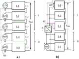
图2a、图2b示出了根据图1的具有级联逆变器单元的电外科发生器的多电平逆变器的实施例的框图;Figures 2a, 2b show a block diagram of an embodiment of a multilevel inverter of an electrosurgical generator with cascaded inverter units according to Figure 1;
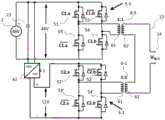
图3示出了逆变器单元中的两个逆变器单元的示意性电路图;Fig. 3 shows a schematic circuit diagram of two inverter units in the inverter unit;
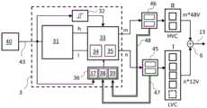
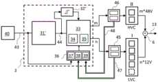
图4a、图4b示出了具有用于驱控高电压和低电压的逆变器单元的调制器的选择器的实例的框图;Figures 4a, 4b show block diagrams of examples of selectors with modulators for driving high voltage and low voltage inverter units;
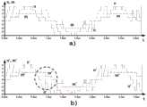
图5示出了根据电压等级切换高电压和低电压的逆变器单元以转换参考信号的简化实例;Fig. 5 shows a simplified example of switching the inverter units of high voltage and low voltage according to the voltage level to convert the reference signal;
图6示出了用于切换高电压和低电压的逆变器单元以转换参考信号的另一个更复杂的实例;Figure 6 shows another more complex example of an inverter unit for switching high voltage and low voltage to convert the reference signal;
图7示出了根据输出电压的极性和参考信号的上升或下降的调制器的切换规则的表格;Fig. 7 shows a table of switching rules of the modulator according to the polarity of the output voltage and the rising or falling of the reference signal;
图8示出了具有作为图7的变体方案的调制器的可变切换规则的表格;和Figure 8 shows a table with variable switching rules for modulators as a variant of Figure 7; and
图9a、图9b示出了高电压和低电压的逆变器单元的示例性切换曲线,分别考虑和不考虑逆变器单元中的磁饱和。Figures 9a, 9b show exemplary switching curves of inverter units for high and low voltage, with and without considering magnetic saturation in the inverter units, respectively.
具体实施方式Detailed ways
根据本发明实施例的电外科发生器在图1中示出。由附图标记1整体表示的电外科发生器包括外壳11,外壳设置有用于电外科器械16的输出接口14,在所示实施例中,这是电手术刀。它通过高压连接电缆的连接插头15连接到电外科发生器1的输出接口14。能够使用功率控制器12来改变电外科器械16的功率输出。An electrosurgical generator according to an embodiment of the present invention is shown in FIG. 1 . The electrosurgical generator, generally indicated by the
为了对电外科发生器1进行能量供应而配备有直流电压源2,该直流电压源能够通过电源连接电缆(未示出)连接到公共电网并由其供电。直流电压源2在所示的实施例中是电源。其包括一个整流器并向一个直流电压中间电路20馈送直流电压,该直流电压的电平优选是固定的,例如为48伏。然而,不应该排除直流电压电平在0和大约400伏之间可变,由此直流电压的绝对电平能够特别取决于设定的功率、电外科器械16的类型和/或其负载阻抗,这又取决于所处理组织的类型。然而,内部电源不是必需的,因此直流电压供应也能够通过外部电源实现,或者提供直接直流馈电,例如车辆中的24伏或固定应用中的48伏。For supplying the
逆变器由直流电压中间电路20馈电,该逆变器从所供给的直流电压中产生具有在200kHz和4MHz之间的范围内的预定频率的高频交流电压。逆变器被设计为多电平逆变器4,如下面将更详细地解释。多电平逆变器4生成的高频交流电压的频率和波形由逆变器控制器41基于控制信号发生器40(见图4)生成的参考信号43来指定。多电平逆变器4产生的高频交流电压通过输出线13、用于将输出电压升压到几千伏的输出变压器7和低通滤波器8路由,并由隔直电容器17防止不需要的直流分量在用于电外科器械16的连接的输出接头14处输出。此外,由多电平逆变器4产生和输出的高压的电压和电流通过组合电压和电流传感器18测量并且测量信号被馈送到处理单元19,该处理单元存储关于输出电压、电流和施加功率的相应数据作为反馈施加到电外科发生器1的操作控制器10,该操作控制器又与控制信号发生器40通信。电源控制器12还连接到操作控制器10。操作控制器10还被设计成设置各种所谓的模式,这些模式通常是存储的电压/时间曲线。提供选择开关12'供用户选择模式。操作控制器10还与控制信号发生器40一起工作,控制信号发生器40被设计为产生用于输出交流电压的参考信号43,特别是关于幅度、频率、曲线形状和脉冲占空比,并输出传送到逆变器控制器41。An inverter is fed by a DC voltage
多电平逆变器4包括多个串联的逆变器单元5,这些逆变器单元由逆变器控制器41控制。逆变器单元5分为两组I和II,它们分组馈送不同电平的直流电压。第一个标记为“组I”,包括低电压(LVC)的逆变器单元,即图2实例中的三个逆变器单元5-1、5-2到5-3。它们由具有低直流电压的直流电压源供电,在实例中为12V。此外,形成了一组高电压(HVC)的逆变器单元,称为“组II”,在所示实例中在图2中,两个逆变器单元5-4、5-5提供更高的直流电压,在实例中为48V。两组I和II输出的电压使用变压器6相加(见图4a、图4b)。还提供了选择器3,其确定要控制的逆变器单元5,特别是要控制的高电压(HVC)组II的逆变器单元的数量“m”和待设定的低电压(LVC)组I的逆变器单元数量“n”。The
现在参考图2a。在那里所示的实施例中,具有特定直流电压的直流电压源连接到每个逆变器单元5的输入端(在图的左侧显示)。由此,各个逆变器单元5产生交流电压,该交流电压在各个逆变器单元5的输出端(在图中右侧示出)作为交流电压被输出。逆变器单元的数量不受限制并且是任意的。逆变器单元5在图2a中以“5-1”、“5-2”至“5-5”的名称连续编号,其中,数量5是示例性的并且能够提供的任何数量的至少两个逆变器单元。施加到各个逆变器单元5的输入端的直流电压可选地通过导轨50在电势方面耦合。因此,各个逆变器单元5的输出端处的交流电压输出被称为“V_1”、“V_2”到“V_5”。通过串联逆变器单元5,它们的输出电压相加,使得总输出电压为:Reference is now made to Figure 2a. In the embodiment shown there, a DC voltage source with a specific DC voltage is connected to the input of each inverter unit 5 (shown on the left side of the figure). As a result, the individual inverter units 5 generate an AC voltage, which is output as an AC voltage at the output of the individual inverter unit 5 (shown on the right in the figure). The number of inverter units is not limited and is arbitrary. The inverter units 5 are numbered consecutively in FIG. 2a with the designations "5-1", "5-2" to "5-5", wherein the number 5 is exemplary and any number of at least two can be provided. inverter unit. The DC voltage applied to the input of the individual inverter units 5 is optionally coupled in terms of potential via a

与仅具有一个直流电压源的简单设计相比,根据本发明增加了关于直流电压源的复杂性,因为现在需要多个(在实例中:两个)而不是仅一个。但电压等级的数量显著增加,从只有一个直流电压源的11个电压等级到超过两倍的23个电压等级。以这种方式能够达到的电压等级的数量遵循以下公式Compared to a simple design with only one DC voltage source, according to the invention there is an increased complexity with respect to the DC voltage source, since now several (in the example: two) are required instead of just one. But the number of voltage levels has increased significantly, from 11 voltage levels with only one DC voltage source to more than double that of 23 voltage levels. The number of voltage levels that can be achieved in this way follows the formula
2*(mHVc*r+nLVc)+12*(mHVc*r+nLVc)+1
其中,mHVc表示具有较高直流电压的逆变器单元的数量(在上面的实例中m=2),nLVc表示具有较低直流电压的逆变器单元的数量(在上面的实例中n=3),r表示较高与较低的直流电压之比(在上面的例子中r=4)。where mHVc represents the number of inverter units with higher DC voltage (m=2 in the above example), nLVc represents the number of inverter units with lower DC voltage (n=3 in the above example ), r represents the ratio of higher to lower DC voltage (r=4 in the above example).
两个直流电压源不需要在电位上相互隔离,但它们能够共享一个共同的参考电位,如图2a中通过导轨50实现的那样。这也使得能够使用较高的直流电压,例如,中间电路20的直流电压,能够通过直流电压转换器42,特别是直流/直流降压转换器,产生较低的直流电压。在本实例中,它将被设计用于具有4:1降压比的比例电源,如图2b所示。这种比例式电源配置的一个优点是,较高直流电压的变化或波动会以比例形式反映在较低直流电压中,从而保持相对等级。这意味着,例如,输出电压能够通过两种不同的方式增加12V:通常是通过接通另一个12V逆变器单元或通过接通一个48V逆变器单元并断开三个12V逆变器单元。The two DC voltage sources do not need to be electrically isolated from each other, but they can share a common reference potential, as implemented by the
各个逆变器单元5的结构及其相互作用在根据图3的示意性电路图中作为实例示出。总共有两个逆变器单元5-1和5-5在此以级联布置示出,以便还示出它们具有不同幅度的直流电压的供应。电源电压Vin为48V的公共直流电压源2显示在图的左边缘。将稳压电容器23分配给它,因此,两个逆变器单元5-3和5-4被供给直流电压。下面首先参考逆变器单元5-5的电路,它被提供48V电压。提供了四个功率开关,它们充当电流阀并布置在H桥电路中。功率开关是半导体功率开关,例如设计为IGBT、MOS-FET、GaN-FET。功率开关51、53串联形成第一支路,功率半导体52、54也串联形成第二支路。两条支路的中点引出并连接到第一变压器6-5的初级绕组61的两端。变压器6-5还具有次级绕组62,变压比为1:1(应注意,也能够提供不同的变压比,特别是为了实现预放大,例如通过变压1:2)的比例。输送线13连接到次级绕组62并通向电外科发生器1的输出接头14(可能通过未在图3中示出的低通滤波器8和输出变压器7,见图1)。The structure of the individual inverter units 5 and their interaction is shown as an example in the schematic circuit diagram according to FIG. 3 . A total of two inverter units 5 - 1 and 5 - 5 are shown here in a cascaded arrangement in order to also show their supply of DC voltages of different magnitudes. A common
第一支路的两个功率开关51、53由公共信号C1.a控制,该信号以反相形式馈送到功率开关53。相应地,第二支路的两个功率开关52、54也由公共信号C1.b驱动,该信号以反相形式馈送到功率开关52。信号C1.a和C1.b由逆变器控制器41以本身已知的方式产生。这意味着当有来自C1.a的高电平信号时,电源开关51接通并且功率开关53截止,即,第一功率支路是正电位,施加到变压器6-1的初级绕组61的上端子。相应地,在第二功率支路中,当C2.b有HIGH信号时,电源开关54接通,而电源开关52截止。第二功率支路因此将负电位施加到初级绕组61的下端子。对于来自C1.a或C1.b的LOW信号,则相反,即,初级绕组61上的极性反转。因此,交流电压由逆变器单元5-1产生并施加到变压器6-1的初级绕组61。The two
第二逆变器单元5-1具有相同的结构,但是通过比例直流电压转换器42从直流电压源2馈电,这将输入电压降低到四分之一。它因此输出12伏的直流电压,第二逆变器单元5-1以与第一逆变器单元5-5相同的方式被供应。因此,在图中,相同的附图标记用于类似的元件。它由逆变器控制器41产生的控制信号C2.a和C2.b驱动,例如通过本身已知的脉宽调制(PWM),以对应于上述的方式。因此,它在其输出端还输出施加到第二变压器6-1的初级绕组61的交流电压。根据直流电压转换器42的设计,两个逆变器单元5-1和5-5电连接。这意味着由逆变器单元5-1和5-5直接输出的交流电压不能容易地相加,因为它们在电位方面是相互关联的。然而,由于该输出交流电压被馈送到变压器6-1和6-5,因此变压器6-1和6-5输出的交流电压各自是无电位的,并且能够很容易地加在一起以形成公共输出电压,其施加到输出线13上。然而,如果逆变器单元5-1和5-5通过直流电压转换器的适当设计在电位方面去耦,则输出的交流电压也能够通过串联连接而直接相加而无需这些变压器。The second inverter unit 5-1 has the same structure, but is fed from the
以这种方式(以及由其他逆变器单元5-2至5-4)产生和相加的总电压通过输出线13输出,低通滤波器8布置在输出线13的端部。例如,它能够设计为一个包含电感和电容的二阶滤波器。应该注意,变压器6-1到6-n的杂散电感也对低通滤波器的电感有贡献,并且如果需要,能够至少部分地替代它。低通滤波器8被调谐为使得由于多电平逆变器4的逆变器单元5中的功率开关的切换频率而产生的交流电压中的干扰被滤除。低通滤波器8的输出被施加到输出变压器7的初级绕组,其提供连接到次级绕组的输出接头14的电流隔离。还提供了隔直电容器17。其用作防止直流分量被输出到手术器械16的安全元件。The total voltage generated and added in this way (and by the other inverter units 5-2 to 5-4) is output via the
控制信号发生器40产生用于激活多电平逆变器4的参考信号43,特别是基于操作控制器10的规范。这是通常为正弦且具有特定频率和幅度的交流电压信号。现在参考图4a、图4b。参考信号43被施加到选择器3,该选择器由此确定要驱动的逆变器单元5的数量和类型(HVC或LVC),并进而分解成组I的低电压(LVC)的逆变器单元和组II的高电压(HVC)的逆变器单元。为此,选择器3包括等级调节器31和调制器33。等级调节器31被设计为将通常连续的参考信号43转换成电压等级信号。这是指示电压等级数量的离散信号,通常以等级表示,其幅度由组I的低电压(LVC)的逆变器单元的电压产生,在本实例中以12V的等级表示。图6a示出了连续参考信号43和由其形成的等级信号,以12V的等级表示。阶梯曲线示出了电压等级信号并且因此形成了由连续曲线表示的参考信号43的离散化。The
此外,等级调节器31已经能够临时划分其中哪些比例归属于组I的低电压(LVC)的逆变器单元和归属于组II的高电压(HVC)的逆变器单元。例如,在如图4a所示的实施例中,这能够通过最小化达到根据参考信号43的电压所需的逆变器单元的基本数量来完成。这种拆分能够包括两个信号,信号“h”信号用于组II的待接通的高电压(HVC)的逆变器单元的基本数量,以及信号“l”用于组I的待接通的低电压(LVC)的逆变器单元的基本数量。这尤其能够是纯粹的数字划分,例如,84V的电压产生恰好由来自组II的一个高电压(HVC)的逆变器单元和来自组I的三个低电压(LVC)的逆变器单元来控制。Furthermore, the
然而,这些基本数量“h”和“l”不直接用于控制,而是通过调制器33来改变。调制器33旨在降低根据组II的高电压(HVC)的逆变器单元的切换频率。或者,为此切换根据组I的低电压(LVC)的逆变器单元。这将在下面更详细地描述。通过调制器33的划分获得的用于组I的待切换的低电压(LVC)的逆变器单元的数量“n”和用于从组II的待切换高电压(HVC)的逆变器单元的数量“m”根据本发明是不同的并且不是唯一的。However, these basic quantities "h" and "l" are not directly used for control, but are varied by
用于组I的待切换的低电压(LVC)的逆变器单元的由此变化的数量“n”和用于从组II的待切换高电压(HVC)的逆变器单元的变化的数量“m”作为输出信号从调制器33输出,并施加到用于组I的低电压(LVC)的逆变器单元和用于组II的高电压(HVC)的逆变器单元的子控制器45、46。它们以本身已知的方式控制组I中的各个逆变器单元LVC和组II中的HVC。子控制器45、46检测组I的低电压(LVC)的逆变器单元或组II的高电压(HVC)的逆变器单元的各个逆变器单元5的切换数据。其包括占空比、切换操作次数的计数器以及通过各个逆变器单元5及其变压器6的磁通量。它们通过数据线47、48将相应的状态数据传输到调制器33和/或其上游的适配模块36。The thus varied number "n" of inverter units for the low voltage (LVC) to be switched of group I and the varied number of inverter units for the high voltage (HVC) to be switched from group II "m" is output as an output signal from the
调制器33不必连续工作。当电压等级信号或参考值43发生变化时,如果调制器被致动并将电压等级信号分成要待接通的低电压(LVC)的逆变器单元和高电压(HVC)的逆变器单元的数量可能就足够了。为此目的,可选地提供变化检测器32,其监测参考信号43并在存在变化时致动调制器33。
在另一个实施例中,如图4b所示,等级调节器31'的设计不同,因此它只输出离散的参考信号(等级信号)44。由此,调制器33直接确定待切换的高电压(HVC)的逆变器单元的数量“m”和待切换的低电压(LVC)的逆变器单元的数量“n”。这将使用一个简化的例子来解释:等级调节器31'从参考信号43产生离散的等级信号44。调制器33被设计成将等级信号44与等级信号的最后一个先前值进行比较。比较能够显示有增加、减少或恒定。这由变化检测器32'检测。数字“m”和“n”的值仅在增加或减少的情况下进行调整,即仅当与前一个等级信号相比发生变化时。这是使用切换规则来完成的,如下面参考图7和图8中所示的实例进一步解释的。In another embodiment, as shown in FIG. 4 b , the
高电压(HVC)的逆变器单元产生的电压实例如图5中的虚线所示,零线附近的实线是低电压(LVC)的逆变器单元产生的电压。它们一起产生所需的正弦曲线,如量化正弦曲线所示。能够看出,组II中的两个高电压(HVC)的逆变器单元中的每一个只需要每半周期切换一次,并且通过频繁切换低电压(LVC)的逆变器单元来实现进一步的调整。在这里,组I的LVC既增加电压(例如,在从0到0.25μs时间段的起始时),又通过补偿性的反向切换来降低电压,以减少逆变器单元发出的暂时过高的HVC电压(例如,在0.25μs到0.65μs和0.87μs到0.98μs的时间段中)。这样,能够避免高电压(HVC)的逆变器单的切换操作,从而减少它们的数量,也能够减少HVC单元的切换引起的相当大的开关功率损耗。An example of the voltage generated by the high voltage (HVC) inverter unit is shown by the dotted line in Figure 5, and the solid line near the neutral line is the voltage generated by the low voltage (LVC) inverter unit. Together they produce the desired sinusoid, as shown by the quantized sinusoid. It can be seen that each of the two high voltage (HVC) inverter units in group II only needs to be switched once every half cycle, and a further improvement is achieved by frequently switching the low voltage (LVC) inverter units. Adjustment. Here, the LVC of Group I both increases the voltage (for example, at the beginning of the time period from 0 to 0.25 μs) and decreases the voltage by compensating reverse switching to reduce the transient overvoltage emitted by the inverter unit The HVC voltage (for example, in the period of 0.25 μs to 0.65 μs and 0.87 μs to 0.98 μs). In this way, switching operations of high voltage (HVC) inverter cells can be avoided, thereby reducing their number, and also the considerable switching power losses caused by switching of HVC cells can be reduced.
图6b示出了更多逆变器单元的更复杂实例。在此获得的用于组II的待接通的高电压(HVC)的逆变器单元的数量的值“m”由虚线表示,并且用于组I的带接通的低电压(LVC)的逆变器单元的数量表示以实心等级线“n”的形式示出。标有“m”的线的曲线清楚地表明高电压(HVC)的逆变器单元的切换活动显著降低,特别是在参考信号的幅度最大值和过零区域。通过优先考虑低电压(LVC)的逆变器单元的切换活动,能够保护具有较高切换损耗的高电压(HVC)的逆变器单元。Figure 6b shows a more complex example with more inverter units. The value "m" obtained here for the number of inverter units of the high voltage (HVC) to be switched on of group II is indicated by the dotted line, and for the low voltage (LVC) of group I with switched on The number of inverter units is shown in the form of a solid graded line "n". The curve of the line marked with "m" clearly shows that the switching activity of the high voltage (HVC) inverter unit is significantly reduced, especially in the region of the amplitude maximum and zero crossing of the reference signal. By prioritizing the switching activity of low voltage (LVC) inverter units, high voltage (HVC) inverter units with higher switching losses can be protected.
为了实现这一点,在调制器33中实施切换规则34。切换规则基于组II中的两个高电压(HVC)的逆变器单元和组I中的4个低电压(LVC)的逆变器单元的示例性配置,如图4a、图4b中所示。使用变化检测器32,逆变器单元的切换状态仅在参考信号43也变化时才变化。在上升的情况下,切换规则34提供了两种可能的选择:To achieve this, a switching
a)在不改变高电压(HVC)的逆变器单元的情况下,将低电压(LVC)的逆变器单元的电压输出增加1个等级(对应于12V);或者a) increase the voltage output of the low voltage (LVC) inverter unit by 1 step (corresponding to 12V) without changing the high voltage (HVC) inverter unit; or
b)将低电压(LVC)的逆变器单元的电压输出降低3个等级(对应于-36V),将高电压(HVC)的逆变器单元的电压输出提高1个等级(+48V)。b) Reduce the voltage output of the low voltage (LVC) inverter unit by 3 levels (corresponding to -36V), and increase the voltage output of the high voltage (HVC) inverter unit by 1 level (+48V).
两种备选方案a)、b)导致一个等级的相同的电压变化,即+12V。备选方案b)需要切换高电压(HVC)的逆变器单元之一,这是由于与四倍的二次关系与低电压(LVC)的逆变器单元之一相比,电源电压上的切换损耗增加了16倍。此外,低电压(LVC)的逆变器单元有三种切换操作。因此,备选方案b)意味着能量损失比切换规则34的备选方案a)高19倍。Both alternatives a), b) result in the same voltage change of one level, ie +12V. Alternative b) requires switching one of the inverter units of the high voltage (HVC), due to the quadratic relationship with four times compared with one of the inverter units of the low voltage (LVC), the Switching losses are increased by a factor of 16. In addition, the low voltage (LVC) inverter unit has three switching operations. Alternative b) therefore implies an energy loss that is 19 times higher than alternative a) of the switching
图7所示的切换规则34考虑了这些关系。现在参考与电压上升情况有关的左栏。其中,包括a)和b)两种选择。输入参数是输出电压的极性和组I的低电压(LVC)的逆变器单元提供的电压,以LVC的电压等级表示。在这种情况下,“1”代表+12V的输出电压,“4”代表+48V的输出电压,相应地,“-4”代表-48V的输出电压。调制器33现在状态为输出电压的正极性,其电压等级在组I的-4和3之间(对应于-48V到+36V),应用切换规则a),也就是说,I组LVC逆变器单元输出的电压输出增加12V。然而,如果电压等级4已经存在于组I中,则使用替代的切换规则b),其中,组II中的HVC逆变器被切换升高一个等级,导致增加48V,并且组I的LVC逆变器单元被补偿性地向下切换三个等级,对应于-36V,最终导致所需的12V增加。如果输出电压的极性为负,则从-4到-1的相应适配的切换范围适用于切换规则的备选方案a)并且0到4适用于备选方案b)。电压下降情况下的相应切换规则如图7的右栏所示。备选方案a)和b)也适用于此,但其具有从图7中能够看出的适配区域。The switching rules 34 shown in Figure 7 take these relationships into account. Reference is now made to the left column relating to voltage rise conditions. Among them, two options a) and b) are included. The input parameters are the polarity of the output voltage and the voltage supplied by the inverter units of the low voltage (LVC) of group I, expressed in the voltage class of LVC. In this case, "1" represents an output voltage of +12V, "4" represents an output voltage of +48V, and correspondingly, "-4" represents an output voltage of -48V. The
调制器33还能够包括滞后模块35。它旨在检测组II的高电压(HVC)的逆变器单元的切换频率,并在过度切换活动的情况下最大限度地减少其切换操作。为此,滞后模块35例如以这样的方式作用于切换规则34,使得范围限制以这样的方式改变,使得备选方案b)变得更稀少。The
切换规则34及其切换范围能够通过适配模块36来适配,特别是取决于多电平逆变器4及其逆变器单元5的运行条件。适配模块36包括带有补偿单元38的监控单元。它检测组I和II的各个逆变器单元中的磁通量并因此作用于切换规则34的切换范围。结果,能够动态地改变切换规则34的切换范围。如果通过高电压(HVC)的逆变器单元的总磁通量过高,则切换范围会改变,以便这些单元稍后接通并更快断开。为此,能够改变参数B和D,如根据图8的修改的切换规则34所示。相反,如果磁通量太低,则能够使用参数A和C更改切换范围,从而使高电压(HVC)的逆变器单元更早接通,稍后才再次断开。这样,能够平衡磁通量并避免饱和。The switching rules 34 and their switching ranges can be adapted by means of an
此外,适配模块36包括可选的接通时间监视器39。其分别记录了低电压(LVC)和高电压(HVC)的逆变器单元的正电压或负电压输出的持续时间。如果超出某些预设限制,则能够以类似于上述磁饱和的方式动态调整切换范围。然而,也能够提出,相应的高负载逆变器单元被断开一段时间。Furthermore,
具有动态改变的切换范围的适配模块36的效果在图9a和图9b中示出。作为起点,图9a示出了根据切换规则34的切换行为,其中,切换范围不变,如图7所示。如果补偿单元38识别出通过根据组II的高电压(HVC)的逆变器单元的磁通量太低,则适配模块36将参数C移动例如值3。然后这导致对应的根据修改后的切换规则改变切换范围,如图9b所示,参数C=3。这意味着高电压(HVC)的逆变器单元一旦接通,将保持更长的接通时间,即延迟关闭,如线m'所示。这对接通没有影响(这能够通过更改参数A来完成)。低电压(LVC)的逆变器单元的切换活动相应改变,如线n'所示。因此,高电压(HVC)的逆变器单元的接通和断开行为是不对称的,以至于它们在很久以后才会断开。因此,它们的接通时间更长,从而增加了它们的磁通量。因此,动态地改变切换规则34的切换范围实现了增加高电压(HVC)的逆变器单元中的磁通量的期望目标。The effect of the
还提供了可选的峰值检测器37。参考信号43被施加到它。它被设计为检测参考信号43中信号峰值的出现,例如当幅度达到其最大值时。如果检测到这种情况,则峰值检测器37能够作用于调制器33,使得根据切换规则34本身到期的高电压(HVC)的逆变器单元的切换被阻止,并且取而代之的是切换剩余的低电压(LVC)的逆变器单元,以达到最后的电压等级。组I中的这种可选冗余LVC逆变器单元在图4中以虚线示出。以这种方式,人们能够利用这一事实,由于参考信号43,幅度最大值是已知的并且能够容易地获得。峰值检测器37检测到这一点并作用于调制器33以阻止或至少最小化在幅度最大值附近的高电压(HVC)的逆变器单元5的切换。An
Claims (19)
Translated fromChineseApplications Claiming Priority (2)
| Application Number | Priority Date | Filing Date | Title |
|---|---|---|---|
| US202163237395P | 2021-08-26 | 2021-08-26 | |
| US63/237,395 | 2021-08-26 |
Publications (1)
| Publication Number | Publication Date |
|---|---|
| CN115733381Atrue CN115733381A (en) | 2023-03-03 |
Family
ID=83081980
Family Applications (1)
| Application Number | Title | Priority Date | Filing Date |
|---|---|---|---|
| CN202211027722.7APendingCN115733381A (en) | 2021-08-26 | 2022-08-25 | Electrosurgical generator with dynamically improved inverter |
Country Status (6)
| Country | Link |
|---|---|
| US (1) | US20230067224A1 (en) |
| EP (2) | EP4424257A3 (en) |
| JP (1) | JP7465921B2 (en) |
| CN (1) | CN115733381A (en) |
| DE (1) | DE102021122284A1 (en) |
| ES (1) | ES2995167T3 (en) |
Families Citing this family (2)
| Publication number | Priority date | Publication date | Assignee | Title |
|---|---|---|---|---|
| DE102022116328B3 (en)* | 2022-06-29 | 2023-09-07 | Olympus Winter & Ibe Gmbh | Electrosurgical generator with improved inverter control and method of operation |
| EP4437987A1 (en) | 2023-03-29 | 2024-10-02 | Olympus Winter & Ibe GmbH | Electrosurgical generator |
Family Cites Families (10)
| Publication number | Priority date | Publication date | Assignee | Title |
|---|---|---|---|---|
| JP4735188B2 (en)* | 2005-10-25 | 2011-07-27 | 三菱電機株式会社 | Power converter |
| JP5374336B2 (en)* | 2009-12-01 | 2013-12-25 | 三菱電機株式会社 | Power converter |
| EP2514380B1 (en) | 2011-04-21 | 2013-10-02 | Erbe Elektromedizin GmbH | Electrical surgical device with improved cutting |
| US9941813B2 (en)* | 2013-03-14 | 2018-04-10 | Solaredge Technologies Ltd. | High frequency multi-level inverter |
| DE102013005277B3 (en)* | 2013-03-26 | 2014-07-03 | Platinum Gmbh | Inverter circuit for use as multi-level inverter for converting DC voltage into AC voltage, has several switching devices for selectively connecting or disconnecting potentials of intermediate circuit to output of inverter circuit |
| US10898256B2 (en)* | 2015-06-30 | 2021-01-26 | Ethicon Llc | Surgical system with user adaptable techniques based on tissue impedance |
| US9839470B2 (en)* | 2015-06-30 | 2017-12-12 | Covidien Lp | Electrosurgical generator for minimizing neuromuscular stimulation |
| US10582962B2 (en)* | 2016-01-23 | 2020-03-10 | Covidien Lp | System and method for harmonic control of dual-output generators |
| WO2017152181A1 (en)* | 2016-03-04 | 2017-09-08 | Qatar Foundation For Education, Science And Community Development | Cascaded packed u-cell multilevel inverter |
| US10869712B2 (en) | 2016-05-02 | 2020-12-22 | Covidien Lp | System and method for high frequency leakage reduction through selective harmonic elimination in electrosurgical generators |
- 2021
- 2021-08-27DEDE102021122284.2Apatent/DE102021122284A1/ennot_activeWithdrawn
- 2022
- 2022-08-22USUS17/892,611patent/US20230067224A1/enactivePending
- 2022-08-25CNCN202211027722.7Apatent/CN115733381A/enactivePending
- 2022-08-25JPJP2022134148Apatent/JP7465921B2/enactiveActive
- 2022-08-26ESES22192317Tpatent/ES2995167T3/enactiveActive
- 2022-08-26EPEP24189146.4Apatent/EP4424257A3/enactivePending
- 2022-08-26EPEP22192317.0Apatent/EP4140427B1/enactiveActive
Also Published As
| Publication number | Publication date |
|---|---|
| DE102021122284A1 (en) | 2023-03-02 |
| EP4424257A2 (en) | 2024-09-04 |
| JP7465921B2 (en) | 2024-04-11 |
| EP4424257A3 (en) | 2024-11-06 |
| US20230067224A1 (en) | 2023-03-02 |
| EP4140427A1 (en) | 2023-03-01 |
| EP4140427B1 (en) | 2024-07-24 |
| JP2023033230A (en) | 2023-03-09 |
| ES2995167T3 (en) | 2025-02-07 |
Similar Documents
| Publication | Publication Date | Title |
|---|---|---|
| US9168083B2 (en) | HR surgical generator | |
| US6031737A (en) | AC-DC power supply | |
| US8817509B2 (en) | High frequency power supply device | |
| US6031746A (en) | Switching amplifier for generating continuous arbitrary waveforms for magnetic resonance imaging coils | |
| JPH0851790A (en) | Control circuit for inductive load | |
| CN1123952C (en) | Circuit for blocking a semiconductor switching device on overcurrent | |
| RU2482978C2 (en) | Railway vehicle drive motor control circuit | |
| EP2469699A2 (en) | Electrosurgical generator controller for regulation of electrosurgical generator output power | |
| US5942884A (en) | Electronic transformer/regulator | |
| CN115733381A (en) | Electrosurgical generator with dynamically improved inverter | |
| TWI872466B (en) | High power generator and method of supplying high power pulses | |
| CN115721405A (en) | Electrosurgical generator with multilevel inverter for high frequency and high voltage | |
| TWI872465B (en) | High power generator and method of supplying high power pulses | |
| TWI873555B (en) | High power generator and method of supplying high power pulses | |
| TWI873553B (en) | High power generator and method of supplying high power pulses | |
| TWI873556B (en) | High power generator and method of supplying high power pulses | |
| JP2004350354A (en) | Inverter power supply | |
| US20210028690A1 (en) | Half-Bridge Having Power Semiconductors | |
| CN101242144B (en) | A method of controlling a DC-DC converter | |
| KR101113956B1 (en) | Power converter capable multi-mode output and constant power control for medical devices | |
| KR20100069038A (en) | Electric discharge machine | |
| TWI873554B (en) | High power generator and method of supplying high power pulses | |
| CN115671557A (en) | Radio frequency signal generating circuit and electronic equipment | |
| KR20210035886A (en) | Voltage converter | |
| CN113366746A (en) | HV/MV/LV DC/DC converter |
Legal Events
| Date | Code | Title | Description |
|---|---|---|---|
| PB01 | Publication | ||
| PB01 | Publication | ||
| SE01 | Entry into force of request for substantive examination | ||
| SE01 | Entry into force of request for substantive examination |