CN115715080A - Data center heat pipe composite air conditioning system and operation method thereof - Google Patents
Data center heat pipe composite air conditioning system and operation method thereofDownload PDFInfo
- Publication number
- CN115715080A CN115715080ACN202211524290.0ACN202211524290ACN115715080ACN 115715080 ACN115715080 ACN 115715080ACN 202211524290 ACN202211524290 ACN 202211524290ACN 115715080 ACN115715080 ACN 115715080A
- Authority
- CN
- China
- Prior art keywords
- heat
- heat pipe
- output end
- module
- control valve
- Prior art date
- Legal status (The legal status is an assumption and is not a legal conclusion. Google has not performed a legal analysis and makes no representation as to the accuracy of the status listed.)
- Granted
Links
Images


Classifications
- Y—GENERAL TAGGING OF NEW TECHNOLOGICAL DEVELOPMENTS; GENERAL TAGGING OF CROSS-SECTIONAL TECHNOLOGIES SPANNING OVER SEVERAL SECTIONS OF THE IPC; TECHNICAL SUBJECTS COVERED BY FORMER USPC CROSS-REFERENCE ART COLLECTIONS [XRACs] AND DIGESTS
- Y02—TECHNOLOGIES OR APPLICATIONS FOR MITIGATION OR ADAPTATION AGAINST CLIMATE CHANGE
- Y02B—CLIMATE CHANGE MITIGATION TECHNOLOGIES RELATED TO BUILDINGS, e.g. HOUSING, HOUSE APPLIANCES OR RELATED END-USER APPLICATIONS
- Y02B30/00—Energy efficient heating, ventilation or air conditioning [HVAC]
- Y02B30/56—Heat recovery units
Landscapes
- Compression-Type Refrigeration Machines With Reversible Cycles (AREA)
- Devices That Are Associated With Refrigeration Equipment (AREA)
Abstract
Description
Translated fromChinese技术领域technical field
本发明涉及制冷与空调技术领域,特别是一种数据中心热管复合空调系统及其运行方法。The invention relates to the technical field of refrigeration and air conditioning, in particular to a data center heat pipe composite air conditioning system and an operating method thereof.
背景技术Background technique
随着互联网数据中心(IDC)的快速增长,其处理的数据呈几何倍数级增长,数据中心装载的大量大功率电子设备在不间断的运行过程中将产生大量热量,对数据中心进行降温的制冷系统消耗了巨大的电力能源。据统计IDC空调制冷系统的能耗约占数据中心总能耗的30%~50%,这已经影响到数据中心的运行成本等,降低冷却设备的能耗成为迫切需要。With the rapid growth of the Internet Data Center (IDC), the data it processes increases geometrically, and a large number of high-power electronic equipment loaded in the data center will generate a lot of heat during uninterrupted operation, cooling the data center. The system consumes a huge amount of electrical energy. According to statistics, the energy consumption of IDC air-conditioning and refrigeration systems accounts for about 30% to 50% of the total energy consumption of the data center, which has already affected the operating costs of the data center, and it is urgent to reduce the energy consumption of cooling equipment.
现有的数据中心的制冷系统和方法包括采用室外的自然散热模块或与备用室外散热模块共同实现散热,例如中国专利CN114599199A中公开的一种数据中心的制冷系统;以及采用机房外部空气单向流动和内循环散热制冷结合方式实现灵活制冷,例如中国专利CN114126322A中公开的一种制冷系统与数据中心;以及采用自然冷却装置、风机盘管、机械制冷设备等的组合控制进行高性能的制冷,例如中国专利CN115023094A中公开的一种数据中心增程式制冷系统及数据中心。上述现有技术虽然都提高了制冷效率,然而其对自然冷源的利用率仍不高,且对于数据中心低品位余热的回收率不高导致能耗仍较高;数据中心采用的机柜多是地板送风方式,机柜内气温随所处位置高度升高而增加,从而导致机柜内冷气流分布不均匀,使得散热高电子设备容易发生故障。因此,如何设计高效且热量回收率高的空调系统是目前仍需解决的问题。Existing refrigeration systems and methods for data centers include using outdoor natural heat dissipation modules or jointly realizing heat dissipation with a spare outdoor heat dissipation module, such as a data center refrigeration system disclosed in Chinese patent CN114599199A; Combined with internal circulation heat dissipation and refrigeration to achieve flexible refrigeration, such as a refrigeration system and data center disclosed in Chinese patent CN114126322A; and the combination control of natural cooling devices, fan coils, mechanical refrigeration equipment, etc. A data center extended-range refrigeration system and a data center disclosed in Chinese patent CN115023094A. Although the above-mentioned existing technologies have improved the cooling efficiency, the utilization rate of the natural cold source is still not high, and the recovery rate of the low-grade waste heat in the data center is not high, resulting in high energy consumption; most of the cabinets used in the data center are In the floor air supply mode, the air temperature in the cabinet increases with the height of the location, resulting in uneven distribution of cold air in the cabinet, making electronic equipment with high heat dissipation prone to failure. Therefore, how to design an air-conditioning system with high efficiency and high heat recovery rate is still a problem to be solved.
发明内容Contents of the invention
本发明的目的是克服现有技术的上述不足而提供一种数据中心热管复合空调系统及其运行方法。The object of the present invention is to overcome the above shortcomings of the prior art and provide a data center heat pipe composite air conditioning system and its operating method.
本发明的技术方案是:数据中心热管复合空调系统,包括热管模块、机械冷却模块、备用制冷模块及余热回收模块。The technical solution of the present invention is: a data center heat pipe composite air conditioning system, including a heat pipe module, a mechanical cooling module, a standby refrigeration module and a waste heat recovery module.
所述热管模块包括机柜内的第一热管蒸发器、第二热管蒸发器、第三热管蒸发器、第一节流装置、第二节流装置、第三节流装置和机柜外的氟泵、第一储液器;第一热管蒸发器、第二热管蒸发器和第三热管蒸发器输入端分别与第一节流装置、第二节流装置、第三节流装置输出端连接,第一节流装置、第二节流装置、第三节流装置输入端均与氟泵输出端连接,氟泵输入端与第一储液器输出端连接。The heat pipe module includes a first heat pipe evaporator, a second heat pipe evaporator, a third heat pipe evaporator, a first throttling device, a second throttling device, a third throttling device and a fluorine pump outside the cabinet, The first liquid reservoir; the input ends of the first heat pipe evaporator, the second heat pipe evaporator and the third heat pipe evaporator are respectively connected to the output ends of the first throttling device, the second throttling device, and the third throttling device, and the first The input ends of the throttling device, the second throttling device, and the third throttling device are all connected to the output end of the fluorine pump, and the input end of the fluorine pump is connected to the output end of the first liquid reservoir.
所述机械冷却模块包括单向阀、气液分离器、压缩机、冷凝器、第二储液器、第四节流装置、第一电磁阀、第一循环泵、风冷冷水机组、第二循环泵、第一带流量控制的止回阀和第二带流量控制的止回阀;单向阀输出端与气液分离器输入端连接,气液分离器输出端与压缩机输入端连接,压缩机输出端与冷凝器第一输入端连接,冷凝器第一输出端与第二储液器输入端连接,第二储液器输出端与第四节流装置输入端连接,第四节流装置输出端与第一电磁阀输入端连接;冷凝器第二输出端依次与第一带流量控制止回阀、第二带流量控制的止回阀和第一循环泵的输入端连接,第一循环泵输出端与风冷式冷水机组输入端连接,风冷式冷水机组输出端与第二循环泵输入端连接,第二循环泵输出端与与冷凝器第二输入端连接。The mechanical cooling module includes a one-way valve, a gas-liquid separator, a compressor, a condenser, a second liquid reservoir, a fourth throttling device, a first solenoid valve, a first circulating pump, an air-cooled chiller, a second circulation pump, the first check valve with flow control and the second check valve with flow control; the output end of the check valve is connected to the input end of the gas-liquid separator, and the output end of the gas-liquid separator is connected to the input end of the compressor. The output end of the compressor is connected to the first input end of the condenser, the first output end of the condenser is connected to the input end of the second accumulator, the output end of the second liquid accumulator is connected to the input end of the fourth throttling device, and the fourth throttling device The output end of the device is connected to the input end of the first solenoid valve; the second output end of the condenser is connected to the first check valve with flow control, the second check valve with flow control and the input end of the first circulation pump in turn, and the first The output end of the circulating pump is connected to the input end of the air-cooled chiller, the output end of the air-cooled chiller is connected to the input end of the second circulating pump, and the output end of the second circulating pump is connected to the second input end of the condenser.
所述余热回收模块包括第一控制阀、第二控制阀、供热端、第三控制阀、第四控制阀、板式换热器和蓄热装置;第一控制阀输出端与供热端输入端连接,供热端输出端与第二控制阀输入端连接;第三控制阀输出端经过板式换热器与第四控制阀输入端连接。The waste heat recovery module includes a first control valve, a second control valve, a heat supply end, a third control valve, a fourth control valve, a plate heat exchanger and a heat storage device; the output end of the first control valve and the input end of the heat supply end The output end of the heat supply end is connected to the input end of the second control valve; the output end of the third control valve is connected to the input end of the fourth control valve through a plate heat exchanger.
所述备用制冷模块包括备用蒸发器、第五节流装置、第二电磁阀和第三电磁阀;备用蒸发器输入端与第五节流装置输出端连接,第五节流装置输入端与第二电磁阀输出端连接,备用蒸发器输出端与第三电磁阀输入端连接。The standby refrigeration module includes a standby evaporator, a fifth throttling device, a second solenoid valve, and a third solenoid valve; the input end of the spare evaporator is connected to the output end of the fifth throttling device, and the input end of the fifth throttling device is connected to the output end of the fifth throttling device. The output ends of the second electromagnetic valve are connected, and the output end of the standby evaporator is connected with the input end of the third electromagnetic valve.
所述三流体换热器包括同心的内管、外管和竖直固定在外管外圆周面上的翅片,内管内的空间形成第一工质通道,内管和外管之间的通道形成第二工质通道。The three-fluid heat exchanger includes a concentric inner tube, an outer tube and fins vertically fixed on the outer circumferential surface of the outer tube, the space in the inner tube forms the first working medium channel, and the channel between the inner tube and the outer tube forms Second working medium channel.
所述热管模块与三流体换热器的第二工质通道连接,机械冷却模块与三流体换热器的第一工质通道连接,备用制冷模块、余热回收模块均与机械冷却模块连接。The heat pipe module is connected to the second working medium channel of the three-fluid heat exchanger, the mechanical cooling module is connected to the first working medium channel of the three-fluid heat exchanger, and the standby refrigeration module and waste heat recovery module are both connected to the mechanical cooling module.
本发明进一步的技术方案是:所述热管模块中第一热管蒸发器、第二热管蒸发器和第三热管蒸发器输出端均与三流体换热器第二工质通道的输入端连接,热管模块中第一储液器输入端与三流体换热器第二工质通道输出端连接;机械冷却模块中单向阀输入端与三流体换热器第一工质通道输出端连接,机械冷却模块中第一电磁阀输出端与三流体换热器第一工质通道输入端连接;余热回收模块中第一控制阀输入端与冷凝器第二输出端连接,第二控制阀输出端与第一带流量控制的止回阀输出端连接,第三控制阀输入端与第一带流量控制的止回阀输出端连接,第四控制阀输出端与第二带流量控制的止回阀输出端连接;备用制冷模块中第二电磁阀输入端与机械冷却模块中第四节流装置输出端连接,备用制冷模块中第三电磁阀输出端与机械冷却模块中单向阀输出端连接。A further technical solution of the present invention is: the output ends of the first heat pipe evaporator, the second heat pipe evaporator and the third heat pipe evaporator in the heat pipe module are all connected to the input end of the second working medium channel of the three-fluid heat exchanger, and the heat pipe The input end of the first liquid reservoir in the module is connected to the output end of the second working medium channel of the three-fluid heat exchanger; the input end of the check valve in the mechanical cooling module is connected to the output end of the first working medium channel of the three-fluid heat exchanger, and the mechanical cooling The output end of the first solenoid valve in the module is connected to the input end of the first working fluid channel of the three-fluid heat exchanger; the input end of the first control valve in the waste heat recovery module is connected to the second output end of the condenser, and the output end of the second control valve is connected to the second output end of the condenser. The output end of the check valve with flow control is connected, the input end of the third control valve is connected with the output end of the first check valve with flow control, the output end of the fourth control valve is connected with the output end of the second check valve with flow control Connection; the input end of the second solenoid valve in the standby refrigeration module is connected to the output end of the fourth throttling device in the mechanical cooling module, and the output end of the third electromagnetic valve in the standby refrigeration module is connected to the output end of the one-way valve in the mechanical cooling module.
本发明再进一步的技术方案是:所述第一热管蒸发器、第二热管蒸发器和第三热管蒸发器按照自上而下的顺序固定安装在机柜内,机械冷却模块与三流体换热器均安装于数据中心室外。A further technical solution of the present invention is: the first heat pipe evaporator, the second heat pipe evaporator and the third heat pipe evaporator are fixedly installed in the cabinet in order from top to bottom, and the mechanical cooling module and the three-fluid heat exchanger All are installed outside the data center.
本发明更进一步的技术方案是:所述第一控制阀、第二控制阀、供热端形成供热端余热回收,第三控制阀、第四控制阀、板式换热器和蓄热装置形成蓄热余热回收。A further technical solution of the present invention is: the first control valve, the second control valve, and the heat supply end form heat supply end waste heat recovery, and the third control valve, fourth control valve, plate heat exchanger, and heat storage device form Heat storage waste heat recovery.
本发明更进一步的技术方案是:所述第一工质通道为机械制冷所用制冷剂流动通道,机械制冷所用制冷剂为R134a;第二工质通道为热管自然冷却所用制冷剂流动通道,热管自然冷却所用制冷剂为二氧化碳。A further technical solution of the present invention is: the first working medium channel is a refrigerant flow channel for mechanical refrigeration, and the refrigerant used for mechanical refrigeration is R134a; the second working medium channel is a refrigerant flow channel for natural cooling of heat pipes, and the heat pipes are naturally The refrigerant used for cooling is carbon dioxide.
本发明提供的另一技术方案是:前述数据中心热管复合空调系统的运行方法,根据室外环境温度选择散热制冷模式,包括,Another technical solution provided by the present invention is: the operation method of the heat pipe composite air conditioning system of the aforementioned data center, which selects the heat dissipation and cooling mode according to the outdoor ambient temperature, including:
A、若室外环境温度小于12℃,启动第一热管蒸发器、第二热管蒸发器、第三热管蒸发器、氟泵以及三流体换热器,热管模块与三流体换热器的第二工质通道连通形成自然冷却制冷回路,制冷剂在三流体换热器第二工质通道内与翅片圆周的冷空气进行换热冷凝,三流体换热器的第二工质通道内冷凝后的制冷剂从其出口依次经过第一储液器、氟泵,再氟泵输出端分别流向第一节流装置、第二节流装置、第三节流装置,在氟泵的作用下流至第一热管蒸发器、第二热管蒸发器、第三热管蒸发器的输出端吸收数据中心的热量,换热后的制冷剂通过三流体换热器输入端回流至第二工质通道,依次循环。A. If the outdoor ambient temperature is lower than 12°C, start the first heat pipe evaporator, the second heat pipe evaporator, the third heat pipe evaporator, the fluorine pump and the three-fluid heat exchanger, the heat pipe module and the second working of the three-fluid heat exchanger The refrigerant channels are connected to form a natural cooling refrigeration circuit. The refrigerant exchanges heat and condenses with the cold air around the fins in the second working medium channel of the three-fluid heat exchanger. After condensation in the second working medium channel of the three-fluid heat exchanger, From its outlet, the refrigerant passes through the first liquid accumulator, the fluorine pump, and then flows to the first throttling device, the second throttling device, and the third throttling device at the output end of the fluorine pump, and flows to the first throttling device under the action of the fluorine pump. The output ends of the heat pipe evaporator, the second heat pipe evaporator, and the third heat pipe evaporator absorb the heat of the data center, and the refrigerant after heat exchange flows back to the second working medium channel through the input end of the three-fluid heat exchanger, and circulates in sequence.
B、若室外环境温度大于12℃且小于40℃,进一步开启单向阀、第一电磁阀,并启动气液分离器、压缩机、冷凝器,第一循环泵、风冷冷水机组、第二循环泵、第一带流量控制的止回阀和第二带流量控制的止回阀;热管模块与三流体换热器的第二工质通道连通形成自然冷却回路,机械冷却模块与三流体换热器的第一工质通道连通形成机械制冷回路,第一工质通道内的制冷剂通过单向阀、气液分离器、压缩机、冷凝器、第二储液器、第四节流装置和第一电磁阀进行循环,并在三流体换热器中第一工质通道内的制冷剂和第二工质通道内的制冷剂进行换热;同时,通过第一循环泵、风冷冷水机组、第二循环泵、第一带流量控制的止回阀、第二带流量控制的止回阀和冷凝器调节第一工质通道内的制冷剂冷凝。B. If the outdoor ambient temperature is greater than 12°C and less than 40°C, further open the one-way valve, the first solenoid valve, and start the gas-liquid separator, compressor, condenser, first circulation pump, air-cooled chiller, second Circulation pump, the first check valve with flow control and the second check valve with flow control; the heat pipe module communicates with the second working medium channel of the three-fluid heat exchanger to form a natural cooling circuit, and the mechanical cooling module communicates with the three-fluid heat exchanger The first working medium channel of the heater is connected to form a mechanical refrigeration circuit, and the refrigerant in the first working medium channel passes through a one-way valve, a gas-liquid separator, a compressor, a condenser, a second liquid receiver, and a fourth throttling device Circulate with the first solenoid valve, and exchange heat between the refrigerant in the first working medium channel and the refrigerant in the second working medium channel in the three-fluid heat exchanger; at the same time, through the first circulating pump, air-cooled cold water The unit, the second circulating pump, the first check valve with flow control, the second check valve with flow control and the condenser regulate the condensation of the refrigerant in the first working medium passage.
C、若室外环境温度大于40℃,或者第一热管蒸发器、第二热管蒸发器或第三热管蒸发器的温度大于23℃,进一步开启备用蒸发器、第二电磁阀和第三电磁阀,温度低于23℃的蒸发器热管模块、机械冷却模块与备用制冷模块形成回路,即备用蒸发器输出端依次与第三电磁阀、气液分离器、压缩机、冷凝器、第二储液器、第四节流装置输入端连接,第四节流装置输出端依次与第二电磁阀、第五节流装置、备用蒸发器输入端连接,通过冷凝器实现对备用蒸发器的换热。C. If the outdoor ambient temperature is greater than 40°C, or the temperature of the first heat pipe evaporator, the second heat pipe evaporator or the third heat pipe evaporator is greater than 23°C, further open the standby evaporator, the second solenoid valve and the third solenoid valve, The heat pipe module of the evaporator with a temperature lower than 23°C, the mechanical cooling module and the standby refrigeration module form a circuit, that is, the output end of the standby evaporator is sequentially connected with the third solenoid valve, gas-liquid separator, compressor, condenser, and second liquid receiver , the input end of the fourth throttling device is connected, the output end of the fourth throttling device is connected with the second electromagnetic valve, the fifth throttling device, and the input end of the standby evaporator in turn, and the heat exchange of the standby evaporator is realized through the condenser.
本发明进一步的技术方案是:还包括,D、在开启机械冷却模块时,采用如下三种方式之一进行余热的回收,The further technical solution of the present invention is: it also includes, D, when opening the mechanical cooling module, adopting one of the following three ways to recover waste heat,
第一种:进一步开启第一控制阀、第二控制阀,调节第一带流量控制的止回阀通过第一控制阀由冷凝器中输出端输出的水流入供热端内的流量,将热量传递至供热端实现供热。The first type: further open the first control valve and the second control valve, adjust the flow rate of the water output from the output end of the condenser through the first control valve through the first control valve, and transfer the heat to the heating end. Transfer to the heat supply end to realize heat supply.
第二种:进一步开启第三控制阀、第四控制阀,调节第二带流量控制的止回阀通过第三控制阀由冷凝器中输出端输出的水流入蓄热装置内的流量,将热量传递至蓄热装置完成蓄热。The second type: further open the third control valve and the fourth control valve, adjust the flow rate of the second check valve with flow control through the third control valve from the output end of the condenser into the heat storage device, and transfer the heat Transfer to heat storage device to complete heat storage.
第三种:开启第一控制阀、第二控制阀、第三控制阀、第四控制阀,分别调节第一带流量控制的止回阀、第二带流量控制的止回阀通过第一控制阀、第三控制阀由冷凝器中输出端输出的温度较高的水流入供热端和蓄热装置内的流量,将热量传递至供热端和蓄热装置。The third method: open the first control valve, the second control valve, the third control valve, and the fourth control valve, respectively adjust the first check valve with flow control and the second check valve with flow control through the first control valve and the third control valve are used to transfer heat to the heat supply end and the heat storage device through the flow of water with a higher temperature output from the output end of the condenser into the heat supply end and the heat storage device.
本发明与现有技术相比具有如下特点:Compared with the prior art, the present invention has the following characteristics:
1、本发明提供的热管复合空调系统采用热管技术、复叠式制冷技术、蒸发压缩制冷技术,根据数据中心室内外温差和数据中心热负荷进行制冷剂流量分配及模式切换,并且复叠式制冷技术的增设拓宽了热管冷却机柜的运行温区,解决了热管在数据中心内外环境温度相差不大时不能较好发挥作用的问题,更好地利用了室外的自然冷源。1. The heat pipe composite air conditioning system provided by the present invention adopts heat pipe technology, cascade refrigeration technology, and evaporative compression refrigeration technology, and performs refrigerant flow distribution and mode switching according to the indoor and outdoor temperature difference of the data center and the heat load of the data center, and cascade refrigeration The addition of technology broadens the operating temperature range of heat pipe cooling cabinets, solves the problem that heat pipes cannot function well when the ambient temperature difference between the inside and outside of the data center is not large, and makes better use of outdoor natural cold sources.
2、本发明提供的热管复合空调系统设置余热回收模块来吸收数据中心设备产生的低品位余热,且在三流体换热器中相变传热比液相、气相换热器的换热效果更好,吸收的低品位余热更多,所需换热器面积更小。2. The heat pipe composite air conditioning system provided by the present invention is equipped with a waste heat recovery module to absorb the low-grade waste heat generated by the data center equipment, and the heat transfer effect of phase change in the three-fluid heat exchanger is better than that of the liquid phase and gas phase heat exchangers Well, more low-grade waste heat is absorbed and less heat exchanger area is required.
3、本发明提供的热管复合空调系统采用三分路热管蒸发器并联方式对机柜进行冷却,通过调节制冷剂在三分路热管蒸发器中的流量,能够调节机柜上中下各部分的制冷效果,从而减少温度差异,遏制机柜内局部过热现象出现。3. The heat pipe composite air conditioning system provided by the present invention uses three-way heat pipe evaporators in parallel to cool the cabinet, and by adjusting the flow of refrigerant in the three-way heat pipe evaporator, the cooling effect of the upper, middle and lower parts of the cabinet can be adjusted , thereby reducing temperature differences and curbing local overheating in the cabinet.
以下结合附图和具体实施方式对本发明的详细结构作进一步描述。The detailed structure of the present invention will be further described below in conjunction with the accompanying drawings and specific embodiments.
附图说明Description of drawings
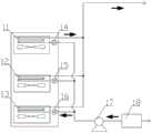
图1为热管复合空调系统结构连接图;Figure 1 is a structural connection diagram of the heat pipe composite air conditioning system;
图2为热管自然冷却模块结构图;Figure 2 is a structural diagram of the heat pipe natural cooling module;
图3为机械冷却模块结构图;Figure 3 is a structural diagram of the mechanical cooling module;
图4(a)、(b)为余热回收模块的供热端和蓄热结构图;Figure 4 (a), (b) is the heat supply end and heat storage structure diagram of the waste heat recovery module;
图5为备用制冷模块结构图;Figure 5 is a structural diagram of the standby refrigeration module;
图6为三流体换热器结构图;Fig. 6 is a structural diagram of a three-fluid heat exchanger;
图7为数据中心热管复合空调系统的运行方式流程图。Fig. 7 is a flow chart of the operation mode of the data center heat pipe composite air conditioning system.
具体实施方式Detailed ways
实施例一,如图1-6所示,数据中心热管复合空调系统,包括热管模块1、机械冷却模块2、余热回收模块3、备用制冷模块4和三流体换热器5。Embodiment 1, as shown in Figures 1-6 , a data center heat pipe composite air conditioning system includes a heat pipe module 1 , a mechanical cooling module 2 , a waste heat recovery module 3 , a backup refrigeration module 4 and a three-fluid heat exchanger 5 .
所述热管模块1包括机柜内的第一热管蒸发器11、第二热管蒸发器12、第三热管蒸发器13、第一节流装置14、第二节流装置15、第三节流装置16和机柜外的氟泵17、第一储液器18。The heat pipe module 1 includes a first
第一热管蒸发器11、第二热管蒸发器12和第三热管蒸发器13按照自上而下的顺序固定安装在机柜内,第一热管蒸发器11、第二热管蒸发器12和第三热管蒸发器13输入端分别与第一节流装置14、第二节流装置15、第三节流装置16输出端连接,第一节流装置14、第二节流装置15、第三节流装置16输入端均与氟泵7输出端连接,氟泵17输入端与第一储液器18输出端连接。The first
所述机械冷却模块2包括单向阀21、气液分离器22、压缩机23、冷凝器24、第二储液器25、第四节流装置26、第一电磁阀27、第一循环泵28、风冷冷水机组29、第二循环泵210、第一带流量控制的止回阀211和第二带流量控制的止回阀212。The mechanical cooling module 2 includes a one-
单向阀21输出端与气液分离器22输入端连接,气液分离器22输出端与压缩机23输入端连接,压缩机23输出端与冷凝器24第一输入端连接,冷凝器24第一输出端与第二储液器25输入端连接,第二储液器25输出端与第四节流装置26输入端连接,第四节流装置26输出端与第一电磁阀27输入端连接;冷凝器24第二输出端依次与第一带流量控制止回阀211、第二带流量控制的止回阀212和第一循环泵28输入端连接,第一循环泵28输出端与风冷式冷水机组29输入端连接,风冷式冷水机组29输出端与第二循环泵210输入端连接,第二循环泵210输出端与与冷凝器24第二输入端连接。The output end of the one-
所述余热回收模块3包括第一控制阀31、第二控制阀32、供热端33、第三控制阀34、第四控制阀35、板式换热器36和蓄热装置37。其中第一控制阀31、第二控制阀32、供热端33形成供热端余热回收,第三控制阀34、第四控制阀35、板式换热器36和蓄热装置37形成蓄热余热回收。The waste heat recovery module 3 includes a
第一控制阀31输出端与供热端33输入端连接,经过用户供暖后,供热端33输出端与第二控制阀32输入端连接;第三控制阀34输出端经过板式换热器36然后与第四控制阀35输入端连接,板式换热器36与蓄热装置37连接以实现板式换热器36和蓄热装置37之间的换热。The output end of the
所述备用制冷模块4包括备用蒸发器41、第五节流装置42、第二电磁阀43和第三电磁阀44。The standby refrigeration module 4 includes a
备用蒸发器41输入端与第五节流装置42输出端连接,第五节流装置42输入端与第二电磁阀43输出端连接,备用蒸发器41输出端与第三电磁阀44输入端连接。The input end of the
所述三流体换热器5包括同心的内管51、外管52和竖直固定在外管外圆周面上的翅片53,内管51内的空间形成第一工质通道,为机械制冷所用制冷剂流动通道;内管51和外管52之间的通道形成第二工质通道,为热管自然冷却所用制冷剂流动通道,翅片53之间的间隔能够使得空气在其间流动,以带走外管52内的热量。The three-fluid heat exchanger 5 includes a concentric
机械制冷所用制冷剂选择对设备承压要求不高且环保的制冷剂,例如R134a等,由于这类制冷剂对冷凝器等设备承压能力要求较二氧化碳对设备要求低,所以机械制冷回路的采用的设备制造成本相对较低。热管自然冷却所用制冷剂选择二氧化碳(CO2),CO2对臭氧层无破坏作用,具有更好的传热特性,且安全无毒,不可燃,不爆炸,即使出现泄漏,数据中心不会有太大损失,而且CO2热管所需要驱动温差较小,能够更加充分地利用自然冷源。Refrigerants used in mechanical refrigeration are environmentally friendly refrigerants that do not require high pressure on equipment, such as R134a, etc. Since this type of refrigerant has lower requirements on the pressure bearing capacity of condensers and other equipment than carbon dioxide on equipment, the use of mechanical refrigeration circuits The manufacturing cost of the equipment is relatively low. The refrigerant used for natural cooling of the heat pipe is carbon dioxide (CO2 ). CO2 has no damage to the ozone layer, has better heat transfer characteristics, is safe, non-toxic, non-flammable, and does not explode. Even if there is a leak, the data center will not have too much damage Large loss, and the CO2 heat pipe needs to drive a smaller temperature difference, which can make full use of the natural cold source.
所述机械冷却模块2和三流体换热器5安装于数据中心室外。The mechanical cooling module 2 and the three-fluid heat exchanger 5 are installed outside the data center.
所述热管模块1中第一热管蒸发器11、第二热管蒸发器12和第三热管蒸发器13输出端均与三流体换热器5第二工质通道的入端连接,热管模块1中第一储液器18输入端与三流体换热器5第二工质通道输出端连接;机械冷却模块2中单向阀21输入端与三流体换热器5第一工质通道输出端连接,机械冷却模块2中第一电磁阀27输出端与三流体换热器5第一工质通道输入端连接;余热回收模块3中第一控制阀31输入端与冷凝器24第二输出端连接,第二控制阀32输出端与第一带流量控制的止回阀211输出端连接,第三控制阀34输入端与第一带流量控制的止回阀211输出端连接,第四控制阀35输出端与第二带流量控制的止回阀212输出端连接;备用制冷模块4中第二电磁阀43输入端与机械冷却模块2中第四节流装置26输出端连接,备用制冷模块4中第三电磁阀44输出端与机械冷却模块2中单向阀21输出端连接。The output ends of the first heat pipe evaporator 11, the second heat pipe evaporator 12 and the third heat pipe evaporator 13 in the heat pipe module 1 are all connected to the input end of the second working medium channel of the three-fluid heat exchanger 5, and the heat pipe module 1 The input end of the first liquid reservoir 18 is connected to the output end of the second working medium channel of the three-fluid heat exchanger 5; the input end of the check valve 21 in the mechanical cooling module 2 is connected to the output end of the first working medium channel of the three-fluid heat exchanger 5 , the output end of the first solenoid valve 27 in the mechanical cooling module 2 is connected to the input end of the first working medium channel of the three-fluid heat exchanger 5; the input end of the first control valve 31 in the waste heat recovery module 3 is connected to the second output end of the condenser 24 , the output end of the second control valve 32 is connected to the output end of the first check valve 211 with flow control, the input end of the third control valve 34 is connected to the output end of the first check valve 211 with flow control, and the fourth control valve 35 The output end is connected to the output end of the second check valve 212 with flow control; the input end of the second electromagnetic valve 43 in the standby refrigeration module 4 is connected to the output end of the fourth throttling device 26 in the mechanical cooling module 2; The output end of the third solenoid valve 44 is connected with the output end of the one-way valve 21 in the mechanical cooling module 2 .
实施例二,如图7所示,实施例一所述的数据中心热管复合空调系统的运行方法,根据室外环境温度选择散热制冷模式,包括如下情形:Embodiment 2, as shown in FIG. 7 , the operation method of the data center heat pipe composite air-conditioning system described in Embodiment 1 selects the heat dissipation and cooling mode according to the outdoor ambient temperature, including the following situations:
A、若室外环境温度小于12℃,启动第一热管蒸发器11、第二热管蒸发器12、第三热管蒸发器13、氟泵17以及三流体换热器5,热管模块1与三流体换热器5的第二工质通道连通形成自然冷却制冷回路,制冷剂在三流体换热器5第二工质通道内与翅片53周围的冷空气进行换热冷凝,三流体换热器5的第二工质通道内冷凝后的制冷剂从其出口依次经过第一储液器18、氟泵17,由氟泵17输出端分别流向第一节流装置14、第二节流装置15、第三节流装置16,在氟泵7的作用下流至第一热管蒸发器1、第二热管蒸发器2、第三热管蒸发器3的输出端吸收数据中心的热量,换热后的制冷剂通过三流体换热器5输入端回流至第二工质通道,依次循环,实现数据中心的自然冷却。A. If the outdoor ambient temperature is lower than 12°C, start the first
其中,第一热管蒸发器11、第二热管蒸发器12、第三热管蒸发器13均设有与其相连接的第一节流装置14、第二节流装置15、第三节流装置16,能够单独对每一个热管蒸发器进行制冷剂流量的调节,同时,控制系统对风机转速进行调节,使得数据中心机柜进风口处沿高度方向温度更加均匀,减少冷热气流掺混,遏制局部过热现象出现。Wherein, the first
B、若室外环境温度大于12℃且小于40℃,进一步开启单向阀21、第一电磁阀27,并启动气液分离器22、压缩机23、冷凝器24,第一循环泵28、风冷冷水机组29、第二循环泵210、第一带流量控制的止回阀211和第二带流量控制的止回阀212。热管模块1与三流体换热器5的第二工质通道连通形成自然冷却回路,机械冷却模块2与三流体换热器5的第一工质通道连通形成机械制冷回路,第二工质通道内的制冷剂实现数据中心的自然冷却散热制冷,此时室外环境温度较高,三流体换热器5翅片53周围的冷空气无法实现数据中心的完全冷却,因此,机械制冷回路对第二工质通道内的制冷剂进行进一步的冷凝:第一工质通道内的制冷剂通过单向阀21、气液分离器22、压缩机23、冷凝器24、第二储液器25、第四节流装置26和第一电磁阀27进行循环,并在三流体换热器5中第一工质通道内的制冷剂和第二工质通道内的制冷剂进行换热以提高数据中心的冷却效果。同时,通过第一循环泵28、风冷冷水机组29、第二循环泵210、第一带流量控制的止回阀211、第二带流量控制的止回阀212和冷凝器24调节第一工质通道内的制冷剂的冷凝效果。B. If the outdoor ambient temperature is greater than 12°C and less than 40°C, further open the
C、若室外环境温度大于40℃,或第一热管蒸发器11、第二热管蒸发器12或第三热管蒸发器13的温度大于23℃,进一步开启备用蒸发器41、第二电磁阀43和第三电磁阀44,温度低于23℃的蒸发器热管模块1、机械冷却模块2与备用制冷模块4形成回路,即备用蒸发器41输出端依次与第三电磁阀44、气液分离器22、压缩机23、冷凝器24、第二储液器25、第四节流装置26输入端连接,第四节流装置26输出端依次与第二电磁阀43、第五节流装置42、备用蒸发器41输入端连接,通过冷凝器24实现对备用蒸发器41的换热,进而实现数据中心的备用散热制冷。C. If the outdoor ambient temperature is greater than 40°C, or the temperature of the first
实施例三,实施例三所述的数据中心热管复合空调系统的运行方法与实施例二的运行方法基本类似,其不同之处在于,还包括:Embodiment 3, the operation method of the data center heat pipe composite air conditioning system described in Embodiment 3 is basically similar to the operation method of Embodiment 2, the difference is that it also includes:
D、采用如下三种方式之一进行余热的回收,第一种:进一步开启第一控制阀31、第二控制阀32,调节第一带流量控制的止回阀211通过第一控制阀31由冷凝器24中输出端输出的温度较高的水流入供热端33内的流量,将热量传递至供热端33实现供热;D. Use one of the following three methods to recover waste heat. The first method: further open the
第二种:进一步开启第三控制阀34、第四控制阀35,调节第二带流量控制的止回阀212通过第三控制阀34由冷凝器24中输出端输出的温度较高的水流入蓄热装置37内的流量,将热量传递至蓄热装置37完成蓄热;The second type: further open the
第三种开启第一控制阀31、第二控制阀32、第三控制阀34、第四控制阀35,分别调节第一带流量控制的止回阀211、第二带流量控制的止回阀212通过第一控制阀31、第三控制阀34由冷凝器24中输出端输出的温度较高的水流入供热端33和蓄热装置37内的流量,将热量传递至供热端33和蓄热装置37,供热端33、蓄热装置37收集的热能根据实际的需要进行再利用,从而实现了余热的回收。The third is to open the
通过上述供热端33和蓄热装置37来对热量进行回收利用,在保证数据中心正常运行的同时,能够进一步提高数据中心能源的利用率,降低能耗。The heat is recovered and utilized through the
Claims (7)
Priority Applications (1)
| Application Number | Priority Date | Filing Date | Title |
|---|---|---|---|
| CN202211524290.0ACN115715080B (en) | 2022-12-01 | 2022-12-01 | Data center heat pipe composite air conditioning system and operation method thereof |
Applications Claiming Priority (1)
| Application Number | Priority Date | Filing Date | Title |
|---|---|---|---|
| CN202211524290.0ACN115715080B (en) | 2022-12-01 | 2022-12-01 | Data center heat pipe composite air conditioning system and operation method thereof |
Publications (2)
| Publication Number | Publication Date |
|---|---|
| CN115715080Atrue CN115715080A (en) | 2023-02-24 |
| CN115715080B CN115715080B (en) | 2025-05-27 |
Family
ID=85235412
Family Applications (1)
| Application Number | Title | Priority Date | Filing Date |
|---|---|---|---|
| CN202211524290.0AActiveCN115715080B (en) | 2022-12-01 | 2022-12-01 | Data center heat pipe composite air conditioning system and operation method thereof |
Country Status (1)
| Country | Link |
|---|---|
| CN (1) | CN115715080B (en) |
Citations (19)
| Publication number | Priority date | Publication date | Assignee | Title |
|---|---|---|---|---|
| CN102538100A (en)* | 2012-02-17 | 2012-07-04 | 合肥工业大学 | Heat pipe composite air conditioning unit for machine room and control method of heat pipe composite air conditioning unit |
| CN102607120A (en)* | 2012-03-27 | 2012-07-25 | 北京工业大学 | Liquid pump driving heat pipe device for cascade mechanical refrigerating and operation method |
| CN105650838A (en)* | 2016-02-24 | 2016-06-08 | 深圳市共济科技有限公司 | Energy-saving control system for data center |
| CN106051969A (en)* | 2016-05-23 | 2016-10-26 | 合肥工业大学 | Control method of combined type air-conditioning system with natural cooling function |
| CN107014016A (en)* | 2017-04-20 | 2017-08-04 | 广东申菱环境系统股份有限公司 | A kind of fluorine pump natural cooling evaporating type condensing cooling-water machine and its control method |
| CN107289670A (en)* | 2017-06-22 | 2017-10-24 | 江苏科技大学 | A kind of Ship Waste Heat cascade utilization formula air-conditioning device and method of work |
| WO2018000601A1 (en)* | 2016-06-29 | 2018-01-04 | 北京丰联奥睿科技有限公司 | Multi-branch heat pipe/heat pump composite system |
| CN109282338A (en)* | 2018-10-16 | 2019-01-29 | 中国科学院理化技术研究所 | Data center waste heat recovery system |
| CN111422027A (en)* | 2020-03-25 | 2020-07-17 | 安徽沃博源科技有限公司 | Vehicle thermal management system and control method thereof |
| CN212390642U (en)* | 2020-06-08 | 2021-01-22 | 青岛科润工业设备有限公司 | Overlapping refrigerating system and overlapping refrigerating system |
| CN113124584A (en)* | 2019-12-30 | 2021-07-16 | 阿里巴巴集团控股有限公司 | Refrigeration system, control method and data center |
| CN113891634A (en)* | 2021-10-26 | 2022-01-04 | 苏州英维克温控技术有限公司 | Cold station unit, integrated cold station system and control method thereof and related equipment |
| CN114126322A (en)* | 2020-08-27 | 2022-03-01 | 华为云计算技术有限公司 | Refrigeration Systems and Data Centers |
| CN114484937A (en)* | 2022-02-25 | 2022-05-13 | 苏州浪潮智能科技有限公司 | Data center waste heat recovery cooling and heating system |
| WO2022110745A1 (en)* | 2020-11-30 | 2022-06-02 | 华为数字能源技术有限公司 | Heat dissipation system, heat management apparatus, and working method thereof |
| WO2022110744A1 (en)* | 2020-11-26 | 2022-06-02 | 华为数字能源技术有限公司 | Data center device |
| CN114599199A (en)* | 2021-12-28 | 2022-06-07 | 北京百度网讯科技有限公司 | Cooling systems for data centers |
| CN114801659A (en)* | 2022-04-22 | 2022-07-29 | 中国科学技术大学 | Self-enthalpy-increasing heat pump mode and thermal management system of modularized pure electric vehicle |
| CN115023094A (en)* | 2021-03-03 | 2022-09-06 | 河北秦淮数据有限公司 | A data center extended program refrigeration system and data center |
- 2022
- 2022-12-01CNCN202211524290.0Apatent/CN115715080B/enactiveActive
Patent Citations (19)
| Publication number | Priority date | Publication date | Assignee | Title |
|---|---|---|---|---|
| CN102538100A (en)* | 2012-02-17 | 2012-07-04 | 合肥工业大学 | Heat pipe composite air conditioning unit for machine room and control method of heat pipe composite air conditioning unit |
| CN102607120A (en)* | 2012-03-27 | 2012-07-25 | 北京工业大学 | Liquid pump driving heat pipe device for cascade mechanical refrigerating and operation method |
| CN105650838A (en)* | 2016-02-24 | 2016-06-08 | 深圳市共济科技有限公司 | Energy-saving control system for data center |
| CN106051969A (en)* | 2016-05-23 | 2016-10-26 | 合肥工业大学 | Control method of combined type air-conditioning system with natural cooling function |
| WO2018000601A1 (en)* | 2016-06-29 | 2018-01-04 | 北京丰联奥睿科技有限公司 | Multi-branch heat pipe/heat pump composite system |
| CN107014016A (en)* | 2017-04-20 | 2017-08-04 | 广东申菱环境系统股份有限公司 | A kind of fluorine pump natural cooling evaporating type condensing cooling-water machine and its control method |
| CN107289670A (en)* | 2017-06-22 | 2017-10-24 | 江苏科技大学 | A kind of Ship Waste Heat cascade utilization formula air-conditioning device and method of work |
| CN109282338A (en)* | 2018-10-16 | 2019-01-29 | 中国科学院理化技术研究所 | Data center waste heat recovery system |
| CN113124584A (en)* | 2019-12-30 | 2021-07-16 | 阿里巴巴集团控股有限公司 | Refrigeration system, control method and data center |
| CN111422027A (en)* | 2020-03-25 | 2020-07-17 | 安徽沃博源科技有限公司 | Vehicle thermal management system and control method thereof |
| CN212390642U (en)* | 2020-06-08 | 2021-01-22 | 青岛科润工业设备有限公司 | Overlapping refrigerating system and overlapping refrigerating system |
| CN114126322A (en)* | 2020-08-27 | 2022-03-01 | 华为云计算技术有限公司 | Refrigeration Systems and Data Centers |
| WO2022110744A1 (en)* | 2020-11-26 | 2022-06-02 | 华为数字能源技术有限公司 | Data center device |
| WO2022110745A1 (en)* | 2020-11-30 | 2022-06-02 | 华为数字能源技术有限公司 | Heat dissipation system, heat management apparatus, and working method thereof |
| CN115023094A (en)* | 2021-03-03 | 2022-09-06 | 河北秦淮数据有限公司 | A data center extended program refrigeration system and data center |
| CN113891634A (en)* | 2021-10-26 | 2022-01-04 | 苏州英维克温控技术有限公司 | Cold station unit, integrated cold station system and control method thereof and related equipment |
| CN114599199A (en)* | 2021-12-28 | 2022-06-07 | 北京百度网讯科技有限公司 | Cooling systems for data centers |
| CN114484937A (en)* | 2022-02-25 | 2022-05-13 | 苏州浪潮智能科技有限公司 | Data center waste heat recovery cooling and heating system |
| CN114801659A (en)* | 2022-04-22 | 2022-07-29 | 中国科学技术大学 | Self-enthalpy-increasing heat pump mode and thermal management system of modularized pure electric vehicle |
Non-Patent Citations (1)
| Title |
|---|
| 白凯洋;马国远;周峰;张双;马跃征;: "全年用泵驱动回路热管及机械制冷复合冷却系统的性能特性", 暖通空调, no. 09, 15 September 2016 (2016-09-15)* |
Also Published As
| Publication number | Publication date |
|---|---|
| CN115715080B (en) | 2025-05-27 |
Similar Documents
| Publication | Publication Date | Title |
|---|---|---|
| CN105180490B (en) | Integrated natural cooling machine room air conditioning system | |
| CN102538100B (en) | Heat pipe compound type air conditioner unit for machine room and control method thereof | |
| CN101701737B (en) | Heat-pump-driven solution dehumidifying air-conditioning device | |
| US20180042140A1 (en) | Server rack heat sink system with combination of liquid cooling device and auxiliary heat sink device | |
| CN104896641B (en) | A kind of double evaporators dynamic ice cold storage system | |
| CN215062980U (en) | Cold and hot combined supply air conditioning system | |
| CN112236022A (en) | A kind of energy-saving cooling system for data center and its realization method | |
| CN114828597A (en) | Disaster recovery data center cooling system based on natural cooling and server level cooling | |
| CN114811997A (en) | A new type of cooling device | |
| CN210892235U (en) | Natural cooling multi-connected refrigerating system with built-in gravity heat pipe | |
| CN215121657U (en) | Water-cooling heat pipe dual-mode machine room air conditioner | |
| KR101272021B1 (en) | Two stage heat pump cooling and heating apparatus | |
| CN202304077U (en) | Air-cooling heat pump unit | |
| CN109869942B (en) | A flat tube casing type heat recovery type heat pump air conditioning system and its working method | |
| CN111102761B (en) | A heat pump-based two-phase fluid circuit temperature control system | |
| CN112954969A (en) | Compact power device heat dissipation system and working method | |
| CN219838412U (en) | Direct heat pump type heat management integrated module and system | |
| JP5240040B2 (en) | Refrigeration equipment | |
| CN217520081U (en) | Refrigerating system and temperature adjusting equipment | |
| CN213687346U (en) | Evaporation cold and hot pump unit | |
| CN115715080A (en) | Data center heat pipe composite air conditioning system and operation method thereof | |
| CN116605005A (en) | A thermal management system for a vehicle and a vehicle | |
| CN115127251A (en) | Multifunctional cold and heat combined supply system and method | |
| CN108332323A (en) | A kind of flat tube plate-fin heat source tower heat pump air-conditioning system and its working method | |
| CN210892240U (en) | Air conditioning system for recovering heat |
Legal Events
| Date | Code | Title | Description |
|---|---|---|---|
| PB01 | Publication | ||
| PB01 | Publication | ||
| SE01 | Entry into force of request for substantive examination | ||
| SE01 | Entry into force of request for substantive examination | ||
| GR01 | Patent grant | ||
| GR01 | Patent grant |