CN115702036A - Contactor module and contactor panel including contactor module - Google Patents
Contactor module and contactor panel including contactor moduleDownload PDFInfo
- Publication number
- CN115702036A CN115702036ACN202180043796.7ACN202180043796ACN115702036ACN 115702036 ACN115702036 ACN 115702036ACN 202180043796 ACN202180043796 ACN 202180043796ACN 115702036 ACN115702036 ACN 115702036A
- Authority
- CN
- China
- Prior art keywords
- contactor
- panel
- membrane
- module
- array
- Prior art date
- Legal status (The legal status is an assumption and is not a legal conclusion. Google has not performed a legal analysis and makes no representation as to the accuracy of the status listed.)
- Pending
Links
Images


Classifications
- B—PERFORMING OPERATIONS; TRANSPORTING
- B01—PHYSICAL OR CHEMICAL PROCESSES OR APPARATUS IN GENERAL
- B01D—SEPARATION
- B01D63/00—Apparatus in general for separation processes using semi-permeable membranes
- B01D63/02—Hollow fibre modules
- B01D63/04—Hollow fibre modules comprising multiple hollow fibre assemblies
- B01D63/043—Hollow fibre modules comprising multiple hollow fibre assemblies with separate tube sheets
- B—PERFORMING OPERATIONS; TRANSPORTING
- B01—PHYSICAL OR CHEMICAL PROCESSES OR APPARATUS IN GENERAL
- B01D—SEPARATION
- B01D63/00—Apparatus in general for separation processes using semi-permeable membranes
- B01D63/02—Hollow fibre modules
- B01D63/021—Manufacturing thereof
- B01D63/0232—Manufacturing thereof using hollow fibers mats as precursor, e.g. wound or pleated mats
- B—PERFORMING OPERATIONS; TRANSPORTING
- B01—PHYSICAL OR CHEMICAL PROCESSES OR APPARATUS IN GENERAL
- B01D—SEPARATION
- B01D63/00—Apparatus in general for separation processes using semi-permeable membranes
- B01D63/14—Pleat-type membrane modules
- B—PERFORMING OPERATIONS; TRANSPORTING
- B01—PHYSICAL OR CHEMICAL PROCESSES OR APPARATUS IN GENERAL
- B01D—SEPARATION
- B01D2313/00—Details relating to membrane modules or apparatus
- B01D2313/06—External membrane module supporting or fixing means
- B—PERFORMING OPERATIONS; TRANSPORTING
- B01—PHYSICAL OR CHEMICAL PROCESSES OR APPARATUS IN GENERAL
- B01D—SEPARATION
- B01D2313/00—Details relating to membrane modules or apparatus
- B01D2313/14—Specific spacers
- B—PERFORMING OPERATIONS; TRANSPORTING
- B01—PHYSICAL OR CHEMICAL PROCESSES OR APPARATUS IN GENERAL
- B01D—SEPARATION
- B01D2313/00—Details relating to membrane modules or apparatus
- B01D2313/54—Modularity of membrane module elements
- B—PERFORMING OPERATIONS; TRANSPORTING
- B01—PHYSICAL OR CHEMICAL PROCESSES OR APPARATUS IN GENERAL
- B01D—SEPARATION
- B01D2315/00—Details relating to the membrane module operation
- B01D2315/22—Membrane contactor
- B—PERFORMING OPERATIONS; TRANSPORTING
- B01—PHYSICAL OR CHEMICAL PROCESSES OR APPARATUS IN GENERAL
- B01D—SEPARATION
- B01D53/00—Separation of gases or vapours; Recovering vapours of volatile solvents from gases; Chemical or biological purification of waste gases, e.g. engine exhaust gases, smoke, fumes, flue gases, aerosols
- B01D53/26—Drying gases or vapours
- B01D53/268—Drying gases or vapours by diffusion
- F—MECHANICAL ENGINEERING; LIGHTING; HEATING; WEAPONS; BLASTING
- F24—HEATING; RANGES; VENTILATING
- F24F—AIR-CONDITIONING; AIR-HUMIDIFICATION; VENTILATION; USE OF AIR CURRENTS FOR SCREENING
- F24F6/00—Air-humidification, e.g. cooling by humidification
- F24F6/02—Air-humidification, e.g. cooling by humidification by evaporation of water in the air
- F24F6/04—Air-humidification, e.g. cooling by humidification by evaporation of water in the air using stationary unheated wet elements
Landscapes
- Chemical & Material Sciences (AREA)
- Chemical Kinetics & Catalysis (AREA)
- Engineering & Computer Science (AREA)
- Analytical Chemistry (AREA)
- General Chemical & Material Sciences (AREA)
- Oil, Petroleum & Natural Gas (AREA)
- Manufacturing & Machinery (AREA)
- Separation Using Semi-Permeable Membranes (AREA)
Abstract
Description
Translated fromChinese技术领域technical field
本公开涉及一种接触器面板。更具体地,本公开涉及一种与接触器面板相关联的接触器模块。The present disclosure relates to a contactor panel. More specifically, the present disclosure relates to a contactor module associated with a contactor panel.
背景技术Background technique
接触器通常用于处理流体以改变流体的质量含量或热含量。因此,接触器可用于蒸发冷却系统、加热系统、加湿系统、除湿系统等。接触器可用于使两种不混溶的流体相(诸如气体/气体、液体/液体、气体/液体)彼此接触,以引起从一种流体到另一种流体的质量传递或热传递。Contactors are commonly used to process fluids to change the mass content or heat content of the fluid. Therefore, the contactor can be used in evaporative cooling systems, heating systems, humidification systems, dehumidification systems, etc. Contactors can be used to bring two immiscible fluid phases (such as gas/gas, liquid/liquid, gas/liquid) into contact with each other to cause mass transfer or heat transfer from one fluid to the other.
此类接触器通常包括安装在框架构件中的接触器介质。常规接触器包括润湿的纤维素介质或膜阵列,诸如在美国专利号9,541,302(下文称为‘302专利)中解释的。‘302专利描述了具有多根中空纤维的平板接触器的使用,该中空纤维实现一种流体与另一种流体的分离和/或从一种流体到另一种流体的传递的功能。Such contactors typically include a contactor media mounted in frame members. Conventional contactors include wetted cellulose media or membrane arrays, such as explained in U.S. Patent No. 9,541,302 (hereinafter the '302 patent). The '302 patent describes the use of a flat panel contactor having a plurality of hollow fibers that perform the function of separation of one fluid from another and/or transfer from one fluid to another.
发明内容Contents of the invention
在大规模应用中,由于空间限制和/或维修更换问题,单个大接触器的使用可能是不可行的。此外,在一些情况下,可以使用多个接触器来实现大规模应用的要求。此外,一些应用可能需要在较小的空间内安装接触器,同时要求接触器的效率高。此类应用可能需要基于空间的可用性和期望的接触器效率将接触器布置成复杂的布置。可能存在这样的情况:其中与多个接触器一起工作可能涉及更长时间的质量传递或热传递、效率限制和其他实施挑战,特别是对于涉及接触器的复杂布置的应用。因此,期望以可提供提高的效率并涉及接触器的更简单结构的方式来配置接触器介质。In large-scale applications, the use of a single large contactor may not be feasible due to space constraints and/or repair replacement issues. In addition, in some cases, multiple contactors can be used to meet the requirements of large-scale applications. Additionally, some applications may require the contactor to fit in a small space while requiring high contactor efficiency. Such applications may require the contactors to be arranged in complex arrangements based on space availability and desired contactor efficiency. There may be situations where working with multiple contactors may involve longer periods of mass or heat transfer, efficiency limitations, and other implementation challenges, especially for applications involving complex arrangements of contactors. Accordingly, it is desirable to configure the contactor media in a manner that provides increased efficiency and involves a simpler structure of the contactor.
本公开的一些实施方案涉及一种用于接触器面板的接触器模块。该接触器模块包括框架构件。该接触器模块还包括联接到该框架构件的接触器介质。该接触器介质限定第一侧和第二侧。该接触器介质包括至少一个第一膜阵列,该至少一个第一膜阵列包括沿第一纤维轴线延伸的多根第一中空纤维。该至少一个第一膜阵列限定第一轴线,该第一轴线大致垂直于该第一纤维轴线并且沿该至少一个第一膜阵列延伸。该接触器模块还包括至少一个第二膜阵列,该至少一个第二膜阵列包括沿第二纤维轴线延伸的多根第二中空纤维。该至少一个第二膜阵列限定第二轴线,该第二轴线大致垂直于该第二纤维轴线并且沿该至少一个第二膜阵列延伸。该至少一个第一膜阵列和该至少一个第二膜阵列被设置成使得在该至少一个第一膜阵列的该第一轴线与该至少一个第二膜阵列的该第二轴线之间限定有第一倾斜角。该第一倾斜角大于零度并且小于180度。Some embodiments of the present disclosure relate to a contactor module for a contactor panel. The contactor module includes a frame member. The contactor module also includes a contactor media coupled to the frame member. The contactor media defines a first side and a second side. The contactor media includes at least one first membrane array including a plurality of first hollow fibers extending along a first fiber axis. The at least one first membrane array defines a first axis that is generally perpendicular to the first fiber axis and extends along the at least one first membrane array. The contactor module also includes at least one second membrane array including a plurality of second hollow fibers extending along a second fiber axis. The at least one second membrane array defines a second axis that is generally perpendicular to the second fiber axis and extends along the at least one second membrane array. The at least one first membrane array and the at least one second membrane array are arranged such that a second axis is defined between the first axis of the at least one first membrane array and the second axis of the at least one second membrane array. an inclination angle. The first tilt angle is greater than zero degrees and less than 180 degrees.
本公开的一些实施方案涉及一种与接触器系统相关联的接触器面板。该接触器面板包括第一集管,该第一集管包括至少一个第一孔口,该至少一个第一孔口允许将第一流体引入该第一集管。该接触器面板还包括第二集管,该第二集管包括至少一个第二孔口,该至少一个第二孔口允许该第一流体从该第二集管流出。接触器面板还包括在该第一集管和该第二集管之间延伸的接触器模块。该接触器模块包括框架构件。该接触器模块还包括联接到该框架构件的接触器介质。该接触器介质限定第一侧和第二侧。该接触器介质包括至少一个第一膜阵列,该至少一个第一膜阵列包括沿第一纤维轴线延伸的多根第一中空纤维。该至少一个第一膜阵列限定第一轴线,该第一轴线大致垂直于该第一纤维轴线并且沿该至少一个第一膜阵列延伸。该接触器介质还包括至少一个第二膜阵列,该至少一个第二膜阵列包括沿第二纤维轴线延伸的多根第二中空纤维。该至少一个第二膜阵列限定第二轴线,该第二轴线大致垂直于该第二纤维轴线并且沿该至少一个第二膜阵列延伸。该至少一个第一膜阵列和该至少一个第二膜阵列被设置成使得在该至少一个第一膜阵列的该第一轴线与该至少一个第二膜阵列的该第二轴线之间限定有第一倾斜角。该第一倾斜角大于零度并且小于180度。Some embodiments of the present disclosure relate to a contactor panel associated with a contactor system. The contactor panel includes a first header including at least one first orifice that allows a first fluid to be introduced into the first header. The contactor panel also includes a second header including at least one second orifice that allows the first fluid to flow out of the second header. The contactor panel also includes a contactor module extending between the first header and the second header. The contactor module includes a frame member. The contactor module also includes a contactor media coupled to the frame member. The contactor media defines a first side and a second side. The contactor media includes at least one first membrane array including a plurality of first hollow fibers extending along a first fiber axis. The at least one first membrane array defines a first axis that is generally perpendicular to the first fiber axis and extends along the at least one first membrane array. The contactor media also includes at least one second membrane array including a plurality of second hollow fibers extending along a second fiber axis. The at least one second membrane array defines a second axis that is generally perpendicular to the second fiber axis and extends along the at least one second membrane array. The at least one first membrane array and the at least one second membrane array are arranged such that a second axis is defined between the first axis of the at least one first membrane array and the second axis of the at least one second membrane array. an inclination angle. The first tilt angle is greater than zero degrees and less than 180 degrees.
本公开的一些实施方案涉及一种用于接触器面板的接触器模块。该接触器模块包括框架构件。该接触器模块还包括联接到该框架构件的接触器介质。该接触器介质限定第一侧和第二侧。该接触器介质包括至少一个第一膜阵列,该至少一个第一膜阵列包括沿第一纤维轴线延伸的多根第一中空纤维。该至少一个第一膜阵列限定第一轴线,该第一轴线大致垂直于该第一纤维轴线并且沿该至少一个第一膜阵列延伸。每根第一中空纤维限定适于接收第一流体的第一内腔和适于接触第二流体的第一外表面。该接触器介质还包括至少一个第二膜阵列,该至少一个第二膜阵列包括沿第二纤维轴线延伸的多根第二中空纤维。该至少一个第二膜阵列限定第二轴线,该第二轴线大致垂直于该第二纤维轴线并且沿该至少一个第二膜阵列延伸。每根第二中空纤维限定适于接收该第一流体的第二内腔和适于接触该第二流体的第二外表面。该至少一个第一膜阵列和该至少一个第二膜阵列被设置成使得在该至少一个第一膜阵列的该第一轴线与该至少一个第二膜阵列的该第二轴线之间限定有第一倾斜角。该第一倾斜角大于零度并且小于180度。Some embodiments of the present disclosure relate to a contactor module for a contactor panel. The contactor module includes a frame member. The contactor module also includes a contactor media coupled to the frame member. The contactor media defines a first side and a second side. The contactor media includes at least one first membrane array including a plurality of first hollow fibers extending along a first fiber axis. The at least one first membrane array defines a first axis that is generally perpendicular to the first fiber axis and extends along the at least one first membrane array. Each first hollow fiber defines a first lumen adapted to receive a first fluid and a first outer surface adapted to contact a second fluid. The contactor media also includes at least one second membrane array including a plurality of second hollow fibers extending along a second fiber axis. The at least one second membrane array defines a second axis that is generally perpendicular to the second fiber axis and extends along the at least one second membrane array. Each second hollow fiber defines a second lumen adapted to receive the first fluid and a second outer surface adapted to contact the second fluid. The at least one first membrane array and the at least one second membrane array are arranged such that a second axis is defined between the first axis of the at least one first membrane array and the second axis of the at least one second membrane array. an inclination angle. The first tilt angle is greater than zero degrees and less than 180 degrees.
附图说明Description of drawings
在这些附图中,类似的符号表示类似的元件。为了容易地识别对任何特定元件或动作的讨论,参考标号中的一个或多个最高有效数位可指首先引入该元件的附图标号。In the drawings, like symbols indicate like elements. To readily identify a discussion of any particular element or act, one or more of the most significant digits in a reference number may refer to the figure number that first introduces that element.
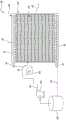
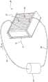
图1示出了根据本文讨论的一些实施方案的接触器系统的示意图。Figure 1 shows a schematic diagram of a contactor system according to some embodiments discussed herein.
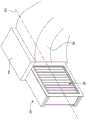
图2示出了根据本文讨论的一些实施方案的与图1的接触器系统相关联的接触器面板的透视图。2 illustrates a perspective view of a contactor panel associated with the contactor system of FIG. 1 , according to some embodiments discussed herein.
图3A示出了根据本文的本公开的一些实施方案的与图2的接触器面板相关联的接触器模块的剖视透视图。3A illustrates a cutaway perspective view of a contactor module associated with the contactor panel of FIG. 2 , according to some embodiments of the disclosure herein.
图3B示出了根据本文的本公开的一些实施方案的接触器介质和邻近该接触器介质设置的分离器结构。Figure 3B illustrates a contactor media and a separator structure disposed adjacent to the contactor media, according to some embodiments of the disclosure herein.
图3C示出了根据本文的本公开的一些实施方案的接触器介质,该接触器介质包括彼此相邻设置的一对连续膜阵列。Figure 3C illustrates a contactor media comprising a pair of continuous membrane arrays disposed adjacent to each other, according to some embodiments of the disclosure herein.
图4示出了根据本文讨论的一些实施方案的与图3A的接触器模块相关联的膜阵列的示意图。4 shows a schematic diagram of a membrane array associated with the contactor module of FIG. 3A, according to some embodiments discussed herein.
图5A示出了根据本文讨论的一些实施方案的编织与图3A的接触器模块相关联的多根中空纤维的第一技术。Figure 5A illustrates a first technique for weaving a plurality of hollow fibers associated with the contactor module of Figure 3A, according to some embodiments discussed herein.
图5B示出了根据本文讨论的一些实施方案的编织与图3A的接触器模块相关联的多根中空纤维的第二技术。Figure 5B illustrates a second technique for weaving a plurality of hollow fibers associated with the contactor module of Figure 3A, according to some embodiments discussed herein.
图6示出了根据本文讨论的一些实施方案的图2的接触器面板的剖视图。Figure 6 illustrates a cross-sectional view of the contactor panel of Figure 2, according to some embodiments discussed herein.
图7A示出了根据本文讨论的一些实施方案的与图3A的接触器模块相关联的第一膜阵列的一部分。Figure 7A illustrates a portion of a first membrane array associated with the contactor module of Figure 3A, according to some embodiments discussed herein.
图7B示出了根据本文讨论的一些实施方案的与图3A的接触器模块相关联的第二膜阵列的一部分。Figure 7B illustrates a portion of a second membrane array associated with the contactor module of Figure 3A, according to some embodiments discussed herein.
图8A和图8B示出了根据本文讨论的一些实施方案的用于接收图2的接触器面板的管道。8A and 8B illustrate conduits for receiving the contactor panel of FIG. 2, according to some embodiments discussed herein.
图8C和图8D示出了根据本文的本公开的一些实施方案的以不同取向安装的图2的接触器面板。8C and 8D illustrate the contactor panel of FIG. 2 installed in different orientations according to some embodiments of the disclosure herein.
图9示出了根据本文讨论的一些实施方案的与图1的接触器系统相关联的接触器面板的组件。FIG. 9 illustrates components of a contactor panel associated with the contactor system of FIG. 1 , according to some embodiments discussed herein.
图10示出了根据本文讨论的一些实施方案的与接触器系统相关联的示例性接触器面板布置。Figure 10 illustrates an example contactor panel arrangement associated with a contactor system, according to some embodiments discussed herein.
图11、图12和图13示出了根据本文讨论的一些实施方案的与图1的接触器系统相关联的接触器介质的各种设计。11, 12, and 13 illustrate various designs of contactor media associated with the contactor system of FIG. 1, according to some embodiments discussed herein.
具体实施方式Detailed ways
在以下描述中,参考形成其一部分的附图,并且其中通过图示的方式示出了各种实施方案。应当理解,在不脱离本公开的范围或实质的情况下,能够设想并作出其他实施方案。因此,以下具体实施方式不应被视为具有限制意义。In the following description, reference is made to the accompanying drawings which form a part hereof, and in which are shown by way of illustration various embodiments. It is to be understood that other embodiments can be conceived and made without departing from the scope or spirit of the present disclosure. Therefore, the following detailed description should not be considered as limiting.
在本公开的上下文中,术语“第一”和“第二”用作标识符。因此,此类术语不应理解为对本公开的限制。在本公开的实施方案的全文中,术语“第一”和“第二”在与特征部或元件结合使用时可互换。In the context of this disclosure, the terms "first" and "second" are used as identifiers. Accordingly, such terms should not be construed as limiting the present disclosure. Throughout the disclosed embodiments, the terms "first" and "second" are interchangeable when used in connection with a feature or element.
本公开一般涉及一种包括接触器模块的接触器面板。该接触器面板可用于空气处理、通风或管道系统中的流体之间的质量传递或热传递。该接触器模块包括具有若干中空纤维的接触器介质。第一流体流过每根中空纤维,而第二流体接触每根中空纤维的外表面。本公开的教导涉及具有可增加第二流体的表面接触面积的改进设计的接触器介质的使用。此外,对于给定尺寸的接触器面板,该接触器介质的布置增加了中空纤维的总数。本文所述的接触器面板可以提供高接触表面积与体积比,这又可转化为紧凑的占地面积和系统尺寸,并且还可提高接触器系统的效率。The present disclosure generally relates to a contactor panel including a contactor module. This contactor panel can be used for mass transfer or heat transfer between fluids in air handling, ventilation or ductwork. The contactor module includes a contactor media with hollow fibers. A first fluid flows through each hollow fiber and a second fluid contacts the outer surface of each hollow fiber. The teachings of the present disclosure relate to the use of contactor media with improved designs that increase the surface contact area of the second fluid. Furthermore, this arrangement of contactor media increases the total number of hollow fibers for a given size of contactor panel. The contactor panels described herein can provide a high contact surface area to volume ratio, which in turn translates into a compact footprint and system size, and can also increase the efficiency of the contactor system.
另外,在本公开中描述的接触器面板的各种实施方案可与空气管道、通风空气管道、回风口(回风口空气格栅)、通风口、扩散器、过滤器外壳、空气处理设备相关联。空气处理设备可包括加热、通风和空调(HVAC)设备;加热、通风、空调和制冷(HVACR或HVAC&R)设备;加热、空调和制冷(HACR)设备;强制通风设备;能量回收通风(ERV)设备;空调(AC)设备;制冷设备;空气处理器等。Additionally, various embodiments of the contactor panels described in this disclosure may be associated with air ducts, ventilation air ducts, return air vents (return air grilles), vents, diffusers, filter housings, air handling equipment . Air handling equipment may include heating, ventilation, and air conditioning (HVAC) equipment; heating, ventilation, air conditioning, and refrigeration (HVACR or HVAC&R) equipment; heating, air conditioning, and refrigeration (HACR) equipment; forced ventilation equipment; energy recovery ventilation (ERV) equipment ; Air conditioning (AC) equipment; refrigeration equipment; air handlers, etc.
图1示出了根据本公开的实施方案的接触器系统100的示意图。本文所述的接触器系统100可以实施为蒸发冷却系统、加热系统、加湿系统和/或除湿系统。在例示的实施方案中,接触器系统100被实施为闭环系统。接触器系统100包括接触器面板106。另外,接触系统100的操作独立于接触器面板106的取向,因为流过接触器面板106的第一流体不会由于重力而滴落。更具体地,接触器系统100包括朝向接触器面板106的部件引导第一流体,并且可不需要将贮存器/分配器定位在一定高度处。FIG. 1 shows a schematic diagram of a
接触器系统100包括罐102。罐102被实施为用于将第一流体容纳在其中的贮存器或容器。在一些示例中,第一流体可基于接触器系统100的应用而被预冷或预热。因此,罐102可以与冷却模块(未示出)或加热模块(未示出)流体连通,以便预冷或预热第一流体。在一个示例中,第一流体是液体和气体中的至少一种。另外,第一流体可包括液体、气体、吹扫气体、空气、强制空气、真空或它们的组合。液体可包括例如冷和/或吸收性液体、盐溶液、热和/或加湿液体或液体干燥剂。第一流体的类型可基于接触器系统100的应用而变化。当接触器系统100被实施为蒸发冷却系统时,罐102将水或空气容纳在其中。此外,当接触器系统100被实施为除湿系统时,罐102将液体干燥剂或空气容纳在其中。
接触器系统100还包括泵104。泵104被设置在第一流体导管105中,该第一流体导管在罐102和接触器面板106之间提供流体连通。泵104对第一流体加压以将加压后的第一流体引入接触器面板106。在一些示例中,泵104可被设计成将第一流体加压到不高于5磅/平方英寸的压力。泵104可进一步允许朝向接触器面板106引导的第一流体的流速变化。第一流体的流速可基于接触器系统100的大小或其应用而变化。在一些示例中,流速可大约等于0.5加仑/分钟(GPM)至1GPM。在其他示例中,第一流体可基于应用的类型以较高流速流动。通过接触器面板106的第一流体流由第一流体流“F1”示出。第一流体经由第一流体导管105从罐102流向接触器面板106。此外,第二流体导管107提供罐102和接触器面板106之间的流体连通。第一流体经由第二流体导管107从接触器面板106流向罐102。在其他实施方案中,接触器系统100可被设计成使得第一流体由于重力而滴落穿过接触器面板106,但不限制本公开的范围。The
此外,接触器系统100包括鼓风机组件108。鼓风机组件108朝向接触器面板106引导第二流体。鼓风机单元108可允许第二流体被推动或拉动穿过接触器面板106。在一个示例性实施方案中,通过接触器面板106的第二流体的流动方向(由图1中的第二流体流“F2”示出)横向于第一流体通过的流动方向。在一些实施方案中,第二流体的流动方向可以是与通过接触器面板106的第一流体的流动方向“平行流动”(相同方向)或“反向流动”(相反方向),如图1中的第一流体流“F1”所示。在一个示例中,第二流体是液体和气体中的至少一种。第二流体可包括液体、气体、吹扫气体、空气、强制空气、真空或它们的组合。液体可包括例如冷和/或吸收性液体、盐溶液、热和/或加湿液体或液体干燥剂。第二流体的类型可基于接触器系统100的应用而变化。在一些示例中,过滤器(未示出)可以定位在接触器面板106的上游,以允许在第二流体接触接触器面板106的接触器模块120之前过滤第二流体。Additionally, the
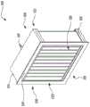
参见图2,示出了与接触器系统100相关联的接触器面板106的透视图。接触器面板106限定前端110和后端112。接触器面板106包括第一集管114,该第一集管包括至少一个第一孔口116,该至少一个第一孔口允许将第一流体引入第一集管114。罐102(参见图1)与第一集管114流体连通。第一集管114适于接收来自罐102的第一流体。更具体地,罐102经由第一流体导管105(参见图1)和第一孔口116与第一集管114流体连通。第一集管114被实施为入口集管。在例示的示例中,第一集管114包括设置为靠近接触器面板106的后端112的单个第一孔口116。另选地,第一集管114可包括一对第一孔口116。第一孔口116相对于第一集管114居中设置并且从第一集管114向外突出。此外,第一集管114通常是立方体形状。Referring to FIG. 2 , a perspective view of the
接触器面板106还包括第二集管118,该第二集管包括至少一个第二孔口117(在图6中示出),该至少一个第二孔口允许第一流体从第二集管118流出。此外,罐102与第二集管118流体连通。第二集管118适于朝向罐102引导第一流体。更具体地,罐102经由第二流体导管107和第二孔口117与第二集管118流体连通。第二集管118被实施为出口集管。在例示的示例中,第二集管118包括设置为靠近接触器面板106的后端112的单个第二孔口117。另选地,第二集管118可包括一对第二孔口117。第二孔口117相对于第二集管118居中设置并且从第二集管118向外突出。此外,第二集管118通常是立方体形状。The
如图所示,接触器系统100包括接触器模块120。接触器模块120在第一集管114和第二集管118之间延伸。接触器模块120包括框架构件122。框架构件122限定设置在接触器面板106的前端110处的框架部分124。参考图3A,接触器模块120还包括联接到框架构件122的接触器介质126。更具体地,接触器介质126由框架构件122支撑。在一个示例中,接触器介质126用作蒸发冷却介质。在另一个示例中,接触器介质126用作除湿介质。接触器介质126限定第一侧128和第二侧130。As shown, the
此外,接触器介质126包括至少一个第一膜阵列132和至少一个第二膜阵列148。该至少一个第一膜阵列132和该至少一个第二膜阵列148类似于美国专利9,541,302(下文称为‘302专利)中描述的中空纤维膜阵列。应当注意,对应于该至少一个第一膜阵列132和该至少一个第二膜阵列148的设计、材料和制造的细节类似于‘302专利中描述的中空纤维膜阵列的设计、材料和制造。Furthermore, the
接触器介质126限定轴线139。接触器介质126包括至少一个第一膜阵列132,该至少一个第一膜阵列包括沿第一纤维轴线136(在图7A中示出)延伸的多根第一中空纤维134(在图7A中示出)。该至少一个第一膜阵列132限定第一轴线133,该第一轴线大致垂直于第一纤维轴线136并沿该至少一个第一膜阵列132延伸。此外,第一中空纤维134在下文中可互换地称为中空纤维134。每根第一中空纤维134限定适于接收第一流体的第一内腔138(在图7A中示出)和适于接触第二流体的第一外表面140(在图7A中示出)。每根第一中空纤维134的壁142(在图7A中示出)将第一内腔138和第一外表面140分开。每根第一中空纤维134限定第一端144(在图7A中示出)和第二端146(在图7A中示出)。第一端144和第二端146被实施为开口端。The
接触器介质126还包括至少一个第二膜阵列148,该至少一个第二膜阵列包括沿第二纤维轴线152(在图7B中示出)延伸的多根第二中空纤维150(在图7B中示出)。该至少一个第二膜阵列148限定第二轴线154,该第二轴线大致垂直于第二纤维轴线152并沿该至少一个第二膜阵列148延伸。此外,第二中空纤维150在下文中可互换地称为中空纤维150。每根第二中空纤维150限定适于接收第一流体的第二内腔156(在图7B中示出)和适于接触第二流体的第二外表面158(在图7B中示出)。每根第二中空纤维150的壁143(在图7B中示出)将第二内腔156和第二外表面158分开。每根第二中空纤维150限定第一端160和第二端162。第一端160和第二端162被实施为开口端。The
此外,该至少一个第一膜阵列132和该至少一个第二膜阵列148被设置成使得在该至少一个第一膜阵列132的第一轴线133与该至少一个第二膜阵列148的第二轴线154之间限定有第一倾斜角“A1”。第一倾斜角“A1”大于零度并且小于180度。在一些实施方案中,第一倾斜角“A1”介于2度和175度之间。此外,在一个示例中,该至少一个第一膜阵列132靠近接触器介质126的第一侧128与该至少一个第二膜阵列148连接,并且该至少一个第一膜阵列132靠近接触器介质126的第二侧130与该至少一个第二膜阵列148间隔开。在另一个示例中,该至少一个第一膜阵列132靠近接触器介质126的第二侧130与该至少一个第二膜阵列148连接,并且该至少一个第一膜阵列132靠近接触器介质126的第一侧128与该至少一个第二膜阵列148间隔开。In addition, the at least one
在一个实施方案中,接触器介质126可包括单个第一膜阵列132和相对于该单个第一膜阵列132成角度地设置的单个第二膜阵列148。然而,在例示的实施方案中,接触器介质126包括多个第一膜阵列132和多个第二膜阵列148。更具体地,接触器介质126是限定该多个第一膜阵列132和该多个第二膜阵列148的连续膜阵列135。此外,接触器介质126包括交替设置的第一膜阵列132和第二膜阵列148。该多个第一膜阵列132基本上彼此平行。此外,该多个第二膜阵列148基本上彼此平行。如接触器介质126的一部分的放大视图所示,第一膜阵列132和相邻设置的第二膜阵列148的接合处包括中空纤维134、150以形成连续膜阵列135。In one embodiment, the
此外,每个第一膜阵列132和相邻设置的第二膜阵列148之间的第一倾斜角“A1”可基于第一膜阵列132的总数、第二膜阵列148的总数、接触器模块120的尺寸等而变化。应当注意,在附图中示出的第一膜阵列132的总数和第二膜阵列148的总数本质上是示例性的,并且第一膜阵列132的实际数量和第二膜阵列148的实际数量可以根据应用需求而变化。In addition, the first inclination angle “A1” between each
此外,接触器介质126限定包括该第一膜阵列132和该第二膜阵列148的多个第一对阵列137。对于每个第一对阵列137,该第一膜阵列132靠近接触器介质126的第一侧128与相邻第二膜阵列148连接,并且每个第一膜阵列132靠近接触器介质126的第二侧130与相邻第二膜阵列148间隔开。此外,接触器介质126限定包括该第一膜阵列132和该第二膜阵列148的多个第二对阵列149。对于每个第二对阵列149,该第一膜阵列132靠近接触器介质126的第二侧130与相邻第二膜阵列148连接,并且该第一膜阵列132靠近接触器介质126的第一侧128与相邻第二膜阵列148间隔开。本文限定的第一膜阵列132和第二膜阵列148的布置可以增加可用体积的接触表面积。此外,较高的接触表面积与体积比可转化为紧凑的系统尺寸。Furthermore, the
使用所述接触器介质126可能造成一些独特的机械挑战,这些机械挑战包括但不限于:第一,防止接触器介质126展开、解开或散开,以及第二,抵抗由第二流体流“F2”引起的负载的要求。接触器介质126两端的压降产生的压差在负载作用于接触器面板106的压力区域时产生负载。The use of the
这些挑战可以通过引入用于结构支撑的第一装置164和第二装置166来解决。更具体地,接触器模块120包括设置为靠近接触器介质126的第一侧128的用于结构支撑的多个第一装置164和设置为靠近接触器介质126的第二侧130的用于结构支撑的多个第二装置166。此外,用于结构支撑的第一装置164和用于结构支撑的第二装置166中的每一者包括杆构件和张紧构件中的至少一种。在一个实施方案中,用于结构支承的第一装置164和用于结构支承的第二装置166被实施为杆构件。更具体地,用于结构支撑的第一装置164和用于结构支撑的第二装置166是杆构件,被实施为刚性制品,包括但不限于棒、板、柱、支柱、双头螺柱、桩、杆、加强件、肋和肋结构、梁、弹簧、拉条、圆柱、框架和导杆。在其他实施方案中,用于结构支撑的第一装置164和用于结构支撑的第二装置166可包括张紧构件,但没有任何限制。更具体地,用于结构支撑的第一装置164和用于结构支撑的第二装置166是张紧构件,被实施为通常柔性的制品,包括但不限于金属丝、细绳、细丝、缆线、带、线、线条、纱、张力弹簧和系带。These challenges can be addressed by introducing
用于结构支撑的第一装置164和用于结构支撑的第二装置166在本文中被实施为在第一集管114和第二集管118之间延伸的杆状部件(参见图2)。接触器介质126围绕用于结构支撑的第一装置164和用于结构支撑的第二装置166中的每一者以缠绕、折叠和打褶中的至少一种方式设置。更具体地,连续膜阵列135可以围绕用于结构支撑的装置164和用于结构支撑的装置中的每一者以V形布置缠绕、折叠或打褶。应当注意,连续膜阵列135沿轴线139缠绕、折叠或打褶。在例示的示例中,连续膜阵列135沿轴线139围绕用于结构支撑的装置164和用于结构支撑的第二装置166打褶。此外,用于结构支撑的第一装置164和用于结构支撑的第二装置166中的每一者可以防止接触器介质126展开、解开或散开。The first means for
该至少一个第一膜阵列132和该至少一个第二膜阵列148中的每一者是微孔的疏水中空纤维膜阵列。更具体地,每个第一膜阵列132和每个第二膜阵列148被实施为微孔的疏水中空纤维膜阵列。由于第一膜阵列132和第二膜阵列148的疏水性质,膜阵列132、148充当惰性载体以允许气相和液相之间直接接触但不会分散。此外,在第一流体和第二流体之间形成屏障。可使用干拉伸工艺制造膜阵列132、148。每个第一膜阵列132和每个第二膜阵列148可由一种或多种聚合物诸如聚烯烃(PO)、聚丙烯(PP)、聚甲基戊烯(PMP)、聚(4-甲基-1-戊烯)等制成。此外,每个第一膜阵列132和每个第二膜阵列148的中空纤维134、150的孔径可以在0.01微米和0.05微米之间。在具体示例中,每个第一膜阵列132和每个第二膜阵列148的中空纤维134、150的孔径可以小于0.04微米。因此,可防止诸如军团菌和/或溶解的矿物进入第二流体,这可降低表面积垢发生的可能性。Each of the at least one
现在参考图3B,示出了与接触器模块120相关联的接触器介质126的一部分。在该实施方案中,接触器模块120可包括邻近接触器介质126设置的至少一个分离器结构302。该至少一个分离器结构302的形状类似于接触器介质126的形状。因此,分离器结构302包括大致V形结构。分离器结构302被设计成使得接触器介质126可以在第一侧128(参见图3A)或第二侧130(参见图3B)处接收分离器结构302。在例示的示例中,分离器结构302包括桁架型分离器。应当注意,本文所示的分离器结构302的形状和设计本质上是示例性的,并且分离器结构302的形状和设计可根据应用需求而变化。在一个示例中,分离器结构302由非织造材料制成。在一些示例中,分离器结构302可由与流经接触器模块120的第二流体相容的金属或塑料制成。在例示的示例中,分离器结构302包括格栅结构,该格栅结构具有多个水平杆构件和多个竖直杆构件。然而,分离器结构302可包括其他设计。例如,分离器结构302可包括蜂窝结构、具有多个通孔的金属片或聚合物片等,但没有任何限制。Referring now to FIG. 3B , a portion of the
分离器结构302为接触器介质126提供支撑,并且可以防止接触器介质126弯曲、展开、解开或散开。分离器结构302减少了中空纤维134、150的偏转,并且为接触器介质126提供抵抗由第二流体施加的压力的结构稳定性。此外,结合分离器结构302可增加接触器模块120的总厚度。增加接触器模块120的厚度可增加流经接触器模块120的第二流体的暴露时间,并且可使接触器模块120两端的压降减小,这进而可以改进接触器模块120的有效性。
图3C示出了本公开的另一个实施方案。在该实施方案中,接触器介质126包括至少两个彼此相邻设置的连续膜阵列304、306。如图所示,接触器介质126包括一对连续膜阵列304、306。然而,应当注意,连续膜阵列304、306的总数可根据应用需求而变化。每个连续膜阵列304、306类似于关于图3A描述的连续膜阵列135。此外,在例示的实施方案中,第一分离器结构308定位在第一连续膜阵列304和第二连续膜阵列306之间。第一分离器结构308类似于关于图3B描述的分离器结构302。Figure 3C illustrates another embodiment of the present disclosure. In this embodiment, the
第一分离器结构308的形状对应于第一连续膜阵列304和第二连续膜阵列306的形状,使得第一分离器结构308可以被接收在第一连续膜阵列304和第二连续膜阵列306之间。此外,与关于图3B解释的分离器结构302类似的第二分离器结构310邻近第一连续膜阵列304设置。第二分离器结构310的形状类似于第一连续膜阵列304的形状。此外,每个分离器结构308、310包括大致V形结构。The shape of the
应当注意,结合多个连续膜阵列304、306和多个分离器结构308、310可增加接触器介质126的总厚度。增加接触器介质126的厚度可增加流经接触器模块120的第二流体的暴露时间,并且可使接触器模块120两端的压降减小,这进而可以改进接触器模块120的有效性。It should be noted that combining multiple
图4示出了关于图3A描述的膜阵列132、148的放大视图。第一膜阵列132和第二膜阵列148包括类似的设计并由类似的材料制成。为此,现在将结合图4一起解释第一膜阵列132和第二膜阵列148的构造。应当注意,本文所示的膜阵列132、148的布置本质上是示例性的。该至少一个第一膜阵列132和该至少一个第二膜阵列148中的每一者包括至少一个膜层167、169。该至少一个膜层167、169包括多根中空纤维134、150。在例示的实施方案中,该至少一个第一膜阵列132和该至少一个第二膜阵列148中的每一者包括彼此相邻设置的多个膜层167、169。更具体地,每个第一膜阵列132和每个第二膜阵列148包括彼此相邻设置的多个膜层167、169。膜层167、169可以沿深度“D1”、“D2”折叠、打褶或缠绕以形成连续膜阵列135(参见图3A)。深度“D1”基本上等于深度“D2”。在例示的实施方案中,每个膜阵列132、148包括六十个膜层,但没有任何限制。在另一个实施方案中,根据应用需求,每个膜阵列132、148可包括二十个膜层或四十个膜层。此外,每个膜层167、169包括八根中空纤维134、150。可以设想,膜层167、169的总数和中空纤维134、150的总数可以根据应用需求而变化。膜层167、169和中空纤维134、150的数量可取决于接触器面板106的期望效率。应当注意,在一些示例中,可通过增加膜层167、169和中空纤维134、150来增加接触器面板106的效率。FIG. 4 shows an enlarged view of the
此外,多根中空纤维134、150被编织以形成关于图3A说明的接触器介质126。更具体地,第一膜阵列132、150的中空纤维134和第二膜阵列148的中空纤维134被编织以形成连续膜阵列135(参见图3A)。第一膜阵列132和第二膜阵列148被编织成可提供高接触表面积与体积比的高效阵列。在一个示例中,如图5A所示,可以使用多根直线502编织中空纤维134、150以形成接触器介质126(参见图3A)。更具体地,可使用直线编织垫技术来编织中空纤维134、150。在另一个示例中,如图5B所示,通过交叉细丝504来编织中空纤维134、150以形成接触器介质126(参见图3A)。更具体地,可使用交叉缠绕垫技术来编织中空纤维134、150。此外,在一些示例中,膜阵列132、148可一起偏斜。细丝502、504可以由与中空纤维134、150的材料类似的材料制成。在一个示例中,细丝502、504可由PP制成。可决定细丝502、504的材料,使得细丝502、504与第二流体相容。In addition, a plurality of
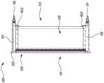
图6示出了图3A的接触器模块120的截面侧视图。如本文所示,为了将接触器模块120与第一集管114和第二集管118联接,使用灌封材料602围绕第一中空纤维134的外径灌封密封每根第一中空纤维134(参见图7A)的第一端144和第二端146(参见图7A)。此外,使用灌封材料602围绕第二中空纤维150(参见图7B)的外径灌封密封每根第二中空纤维150的第一端160和第二端162(参见图7B)。可通过灌封方法(诸如重力灌封方法、模制灌封方法、离心灌封方法等)将各端144、146、160、162嵌入树脂中。灌封材料602可包括环氧树脂、热塑性塑料、聚氨酯等。灌封材料可将每根第一中空纤维134和每根第二中空纤维150密封到第一集管114和第二集管118。应当注意,灌封密封各端144、146、160、162,使得每个第一内腔138和每个第二内腔156分别与第一集管114和第二集管118流体连通。FIG. 6 shows a cross-sectional side view of the
现在参考图7A和图7B,每根第一中空纤维134(参见图7A)限定第一内腔138(参见图7A),并且每根第二中空纤维150(参见图7B)限定第二内腔156(参见图7B)。第一流体适于流过每根第一中空纤维134的第一内腔138和每根第二中空纤维150的第二内腔156。更具体地,由第一集管114(参见图2和图6)朝向每根第一中空纤维134的第一内腔138和每根第二中空纤维150的第二内腔156引导从罐102(参见图1)接收的第一流体。第一流体流过第一内腔138和第二内腔156并被引入第二集管118(参见图2和图6)。第二集管118继而朝向罐102引导第一流体。Referring now to FIGS. 7A and 7B , each first hollow fiber 134 (see FIG. 7A ) defines a first lumen 138 (see FIG. 7A ), and each second hollow fiber 150 (see FIG. 7B ) defines a second lumen. 156 (see Figure 7B). The first fluid is adapted to flow through the
此外,每根第一中空纤维134限定第一外表面140(参见图7A),并且每根第二中空纤维150限定第二外表面158(参见图7B)。第二流体适于接触每根第一中空纤维134的第一外表面140和每根第二中空纤维150的第二外表面158。此外,鼓风机组件108(参见图1)适于朝向每根第一中空纤维134的第一外表面140和每根第二中空纤维150的第二外表面158引导第二流体。Furthermore, each first
此外,与通常包括平膜阵列或润湿纤维素介质的常规接触器介质相比,基于接触表面积的增加,布置成本文所述的V形布置的接触器介质126可提供提高的效率。在一些示例中,接触器介质126可提供为常规接触器介质提供的接触表面积的约4倍至8倍的接触表面积。由于较高的接触表面积与体积比,紧凑的接触器介质126可用于不同的应用。Furthermore,
此外,当接触器面板106(参见图1)与蒸发冷却系统相关联时,第一流体(例如水)流过第一内腔138和第二内腔156,并且第二流体(例如热空气和干空气)流过第一外表面140和第二外表面158。中空纤维134、150的材料可限制第一流体通过壁142、143。因此,只有水蒸气可以通过蒸发从第一内腔138和第二内腔156流向第一外表面140和第二外表面158。此外,当只有水蒸气穿过膜阵列132、148时,可消除对雾捕获屏的需求。Additionally, when contactor panel 106 (see FIG. 1 ) is associated with an evaporative cooling system, a first fluid (eg, water) flows through first and second
应当注意,可以确定中空纤维134、150的孔的尺寸,使得孔可以阻挡细菌和/或其他溶解的矿物进入第二流体。因此,接触器模块120可用于过滤液体、液体除泡等。每根第一中空纤维134和每根第二中空纤维150的壁142、143可分别用作惰性介质,该惰性介质可使第一流体和第二流体直接接触而不分散。此外,释放的第二流体可以是冷湿空气。此外,当接触器面板106用于蒸发冷却系统中时,同时发生热传递和质量传递。应当注意,液相与气相之间的质量传递由气相的压力控制。It should be noted that the pores of the
此外,当接触器面板106与除湿系统相关联时,第一流体可以是液体干燥剂并且第二流体可以是热湿空气。第二流体与流过每根第一中空纤维134的第一内腔138和每根第二中空纤维150的第二内腔156的第一流体接触。基于第二流体在接触器介质126上的流动,第二流体的湿度基于第一流体和第二流体之间的质量传递而降低。释放的第二流体可以是热干空气。此外,当接触器面板106用于除湿系统中时,仅发生质量传递。Additionally, when the
此外,如图8A和图8B所示,管道168适于接收接触器面板106。管道168可以与接触器系统100相关联(参见图1)。管道168限定纵向轴线172。接触器面板106定位在管道168的外壳构件170内。外壳构件170可接收单个接触器面板106或一对接触器面板106。应当注意,接触器面板106相对于管道168的取向可基于应用需求而变化。更具体地,当接触器系统100被实施为闭环系统时,接触器面板120可以以从图8A至图8D明显看出的各种取向安装。在一个示例中,如图8A所示,接触器面板106定位在外壳构件170内,使得每根第一中空纤维134(参见图7A)的第一纤维轴线136(参见图7A)和每根第二中空纤维150(参见图7B)的第二纤维轴线152(参见图7B)基本上垂直于由管道168限定的纵向轴线172。在另一示例中,如图8B所示,接触器面板106定位在外壳构件170内,使得每根第一中空纤维134(参见图7A)的第一纤维轴线136(参见图7A)和每根第二中空纤维150(参见图7B)的第二纤维轴线152(参见图7B)基本上平行于由管道168限定的纵向轴线172。Additionally, as shown in FIGS. 8A and 8B ,
现在参考图8C,接触器面板106也可水平设置。在此类示例中,来自罐102的第一流体可被加压并且经由第一流体导管105朝向接触器面板120引导。第一流体经由第二流体导管107返回到罐102。通过接触器面板106的第一流体流由第一流体流“F1”示出。此外,第二流体可流经接触器面板106。第二流体流由第二流体流“F2”示出。因此,本文所述的接触器面板106可用于在竖直空间可用性方面具有限制的应用或基于接收接触器面板106的管道168(参见图8A和图8B)的形状、尺寸和方向需要以特定取向安装接触器面板106的应用。Referring now to FIG. 8C, the
如图8D所示,接触器面板106可以以角度取向设置。在此类示例中,来自罐102的第一流体可被加压并且经由第一流体导管105朝向接触器面板106引导。第一流体经由第二流体导管107返回到罐102。通过接触器面板的第一流体流由第一流体流“F1”示出。此外,第二流体可流经接触器面板106。第二流体流由第二流体流“F2”示出。因此,本文所述的接触器面板106可用于基于接收接触器面板106的管道168(参见图8A和图8B)的形状、尺寸和方向需要以特定取向安装接触器面板106的应用。As shown in Figure 8D, the
图9示出了本公开的另一个实施方案。在该实施方案中,接触器系统900包括多个接触器面板906的组件902。接触器面板906在设计和构造上与参考图1至图8B说明的接触器系统100相关联的接触器面板106(参见图2)相似。组件902可用多个接触器面板906代替单个大接触器面板。组件902包括接触器面板906的两个阵列908。每个阵列908各自包括四个接触器面板906。然而,阵列908和每个阵列908中的接触器面板906的数量可基于应用需求而变化。此外,每个接触器面板906包括类似于与接触器系统100相关联的第一孔口116的第一孔口916(参见图2)和类似于与接触器系统100相关联的第二孔口117(参见图6)的第二孔口(未示出)。此外,每个阵列908包括类似于与接触器系统100相关联的第一流体导管105(参见图1)的第一流体导管910。第一流体导管910与第一孔口916流体联接。此外,每个阵列908包括类似于与接触器系统100相关联的第二流体导管107(参见图1)的第二流体导管912。第二流体导管912与第二孔口流体联接。第一流体导管910和第二流体导管912可以与类似于与接触器系统100相关联的罐102(参见图1)的罐(未示出)流体连通。代替单个大接触器面板的多个接触器面板906的组件902可以展示出改进的效率,允许更容易地替换和维护、方便地储存/处理接触器面板906、降低替换成本和/或等等。Figure 9 illustrates another embodiment of the present disclosure. In this embodiment, a
图10示出了与接触器系统100类似的接触器系统1000的另一个实施方案。在该实施方案中,接触器系统1000包括接触器面板布置1002。更具体地,接触器系统1000包括限定第一面板轴线1008的至少一个第一接触器面板1004和限定第二面板轴线1010的至少一个第二接触器面板1006。第一面板轴线1008和第二面板轴线1010可以被实施为由相应接触器面板1004、1006的框架构件(未示出)限定的纵向轴线。该至少一个第一接触器面板1004包括第一膜阵列1012,并且该至少一个第二接触器面板1006包括第二膜阵列1014。此外,第一膜阵列1012和第二膜阵列1014中的每一者类似于‘302专利中描述的中空纤维膜阵列。该至少一个第一接触器面板1004和该至少一个第二接触器面板1006被设置成使得在第一面板轴线1008与第二面板轴线1010之间限定有第二倾斜角“A2”。第二倾斜角“A2”大于零度并且小于180度。在一些实施方案中,第二倾斜角“A2”介于2度和175度之间。FIG. 10 shows another embodiment of a
在例示的示例中,接触器系统1000包括多个第一接触器面板1004,使得每个第一接触器面板1004限定第一面板轴线1008。多个第一接触器面板1004基本上彼此平行。此外,接触器系统1000包括多个第二接触器面板1006,使得每个第二接触器面板1006限定第二面板轴线1010。多个第二接触器面板1006基本上彼此平行。此外,每个第一接触器面板1004邻近相应的第二接触器面板1006设置,使得在它们之间限定有第二倾斜角“A2”。更具体地,接触器面板布置1002包括以V形方式布置的接触器面板1004、1006,使得每个第一接触器面板1004相对于相邻的第二接触器面板1006成角度地设置。In the illustrated example,
第一接触器面板1004和第二接触器面板1006中的每一者还分别包括第一孔口1016、1018和允许第一流体引入和流出的第二孔口(未示出)。第一孔口1016、1018和第二孔口可经由流体导管(未示出)与类似于图1的罐102的罐(未示出)流体连通。本文所述的第一接触器面板1004和第二接触器面板1006的布置可通过增加第二流体与第一膜阵列1012和第二膜阵列1014之间的表面接触面积来提高接触器系统1000的有效性。Each of the
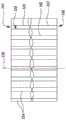
图11、图12和图13示出了本公开的各种实施方案。如图11所示,示出了接触器介质1102。接触器介质1102可以与图1和图2的接触器模块106相关联。接触器介质1102包括与关于图3A描述的连续膜阵列135类似的连续膜阵列1104。连续膜阵列1104包括多个第一膜阵列1106和多个第二膜阵列1108。第一膜阵列1106和第二膜阵列1108的材料类似于关于图3A至图7B描述的第一膜阵列132和第二膜阵列148的材料。如图所示,每个第一膜阵列1106在接合处1110与相邻设置的第二膜阵列1108连接。Figures 11, 12 and 13 illustrate various embodiments of the present disclosure. As shown in Figure 11, a
此外,第一膜阵列1106限定第一轴线1112,并且第二膜阵列1108限定第二轴线1114。在例示的示例中,在第一轴线1112和第二轴线1114之间限定第三倾斜角“A3”。第三倾斜角“A3”大于零度并且小于180度。在一些实施方案中,第三倾斜角“A3”介于2度和175度之间。如图所示,每个第一膜阵列1106和相邻设置的第二膜阵列1108在与接合处1110相对的一端会聚,使得在它们之间限定空间1116。然而,如图所示,在第一膜阵列1106和第二膜阵列1108之间限定的空间1116是最小的,使得每组第一膜阵列1106和第二膜阵列1108基本上是滴状的。Furthermore, the
参考图12,示出了接触器介质1202。接触器介质1202可以与图1和图2的接触器模块106相关联。接触器介质1202包括与关于图3A描述的连续膜阵列135类似的连续膜阵列1204。连续膜阵列1204包括多个第一膜阵列1206和多个第二膜阵列1208。第一膜阵列1206和第二膜阵列1208的材料类似于关于图3A至图7B描述的第一膜阵列132和第二膜阵列148的材料。如图所示,每个第一膜阵列1206在接合处1210与相邻设置的第二膜阵列1208连接。Referring to Figure 12, a
此外,第一膜阵列1206限定第一轴线1212,并且第二膜阵列1208限定第二轴线1214。在例示的示例中,在第一轴线1212和第二轴线1214之间限定第三倾斜角“A3”。第三倾斜角“A3”大于零度并且小于180度。在一些实施方案中,第三倾斜角“A3”介于2度和175度之间。如图所示,每个第一膜阵列1206和相邻设置的第二膜阵列1208在与接合处1210相对的一端会聚,使得在它们之间限定空间1216。应当注意,空间1216大于限定在第一膜阵列1106和第二膜阵列1108(参见图11)之间的空间1116(参见图11)。此外,应当注意,连续膜阵列1204被设计为使得在第一轴线1212和第二轴线1214之间限定的第三倾斜角“A3”小于在第一膜阵列1106的第一轴线1112(参见图11)和第二膜阵列1108的第二轴线1114(参见图11)之间限定的第三倾斜角“A3”。Furthermore,
图13示出接触器介质1302的又一种设计。接触器介质1302可以与图1和图2的接触器模块106相关联。在该实施方案中,接触器介质1302包括与关于图3A描述的连续膜阵列135类似的连续膜阵列1304。连续膜阵列1304包括多个第一膜阵列1306和多个第二膜阵列1308。第一膜阵列1306和第二膜阵列1308的材料类似于关于图3A至图7B描述的第一膜阵列132和第二膜阵列148的材料。如图所示,每个第一膜阵列1306在接合处1310处与相邻设置的第二膜阵列1308连接。在例示的示例中,第一膜阵列1306基本上平行于第二膜阵列1308。如图所示,第一膜阵列1306限定第一轴线1312,并且第二膜阵列1308限定基本上平行于第一轴线1312的第二轴线1314。FIG. 13 shows yet another design of the
当用于蒸发冷却系统中时,由于水蒸气效率高,本文中描述的接触器面板106、906和接触器面板布置1002可能需要减少的水量用于其操作。此外,可以在对接触器系统的设计进行最小改变的情况下在现有接触器系统中对本文所述的接触器面板106、906进行改装。此外,接触器面板106、906和接触器面板布置1002可以互换地用于不同的应用,例如加湿或除湿。应当注意,与本文所述的接触器系统100、900相关联的接触器面板106、906和与本文所述的接触器系统1000相关联的接触器面板布置1002可用于大规模应用中,例如数据中心中。例如,接触器面板106、906和接触器面板布置1002可以与用于冷却数据中心、安装有电子设备的其他房间、商业应用等的蒸发冷却系统相关联。此外,接触器面板106、906和接触器面板布置1002可用于加热、冷却、加湿和/或除湿的各种应用,但不限制本公开的范围。此外,接触器面板106、906和接触器面板布置1002可在紧凑的占地面积中提供改进的冷却性能。When used in an evaporative cooling system, the
本发明的各种实施方案已进行描述。这些实施方案以及其他实施方案均在以下权利要求书的范围内。Various embodiments of the invention have been described. These and other implementations are within the scope of the following claims.
Claims (98)
Applications Claiming Priority (3)
| Application Number | Priority Date | Filing Date | Title |
|---|---|---|---|
| US202063041417P | 2020-06-19 | 2020-06-19 | |
| US63/041,417 | 2020-06-19 | ||
| PCT/IB2021/054327WO2021255546A1 (en) | 2020-06-19 | 2021-05-19 | Contactor module and contactor panel including contactor module |
Publications (1)
| Publication Number | Publication Date |
|---|---|
| CN115702036Atrue CN115702036A (en) | 2023-02-14 |
Family
ID=79268581
Family Applications (1)
| Application Number | Title | Priority Date | Filing Date |
|---|---|---|---|
| CN202180043796.7APendingCN115702036A (en) | 2020-06-19 | 2021-05-19 | Contactor module and contactor panel including contactor module |
Country Status (5)
| Country | Link |
|---|---|
| US (1) | US20230182081A1 (en) |
| EP (1) | EP4168161A4 (en) |
| JP (1) | JP2023531419A (en) |
| CN (1) | CN115702036A (en) |
| WO (1) | WO2021255546A1 (en) |
Families Citing this family (1)
| Publication number | Priority date | Publication date | Assignee | Title |
|---|---|---|---|---|
| CA3165879A1 (en)* | 2021-06-28 | 2022-12-28 | Ingenia Technologies Inc. | Desiccant assembly, system provided with such an assembly, kit for assembling the same, and corresponding methods of manufacturing, assembling and operating associated thereto |
Citations (10)
| Publication number | Priority date | Publication date | Assignee | Title |
|---|---|---|---|---|
| US4911846A (en)* | 1988-05-27 | 1990-03-27 | Kuraray Co., Ltd. | Fluid treating apparatus and method of using it |
| US5104535A (en)* | 1990-08-17 | 1992-04-14 | Zenon Environmental, Inc. | Frameless array of hollow fiber membranes and module containing a stack of arrays |
| US5480553A (en)* | 1992-02-12 | 1996-01-02 | Mitsubishi Rayon Co., Ltd. | Hollow fiber membrane module |
| US5747138A (en)* | 1995-11-30 | 1998-05-05 | Minnesota Mining And Manufacturing Company | Multilayer hollow-fiber body and method of making |
| JP2004101161A (en)* | 2001-12-21 | 2004-04-02 | Mitsubishi Heavy Ind Ltd | Humidifier |
| CN101479024A (en)* | 2006-06-26 | 2009-07-08 | 住友电工超效能高分子股份有限公司 | Filter device |
| CN101888892A (en)* | 2007-12-06 | 2010-11-17 | 日东电工株式会社 | air filter |
| US20130146518A1 (en)* | 2011-12-09 | 2013-06-13 | Daniel Eumine SUK | Hollow fiber membrane module with miniskeins in miniheaders having a zig-zag configuration |
| CN103635250A (en)* | 2011-06-03 | 2014-03-12 | 塞尔格有限责任公司 | Flat panel contactor and method |
| CN106422791A (en)* | 2016-08-31 | 2017-02-22 | 成都美富特膜科技有限公司 | Membrane filtration unit and membrane assembly |
Family Cites Families (12)
| Publication number | Priority date | Publication date | Assignee | Title |
|---|---|---|---|---|
| JPS5634322B2 (en)* | 1973-12-11 | 1981-08-10 | ||
| US5236665A (en)* | 1988-10-20 | 1993-08-17 | Baxter International Inc. | Hollow fiber treatment apparatus and membrane oxygenator |
| US5041220A (en)* | 1990-01-09 | 1991-08-20 | Minntech Corporation | Hollow fiber filter cartridge for a standarized housing |
| US5248424A (en)* | 1990-08-17 | 1993-09-28 | Zenon Environmental Inc. | Frameless array of hollow fiber membranes and method of maintaining clean fiber surfaces while filtering a substrate to withdraw a permeate |
| DE59709659D1 (en)* | 1996-02-01 | 2003-05-08 | Mat Adsorption Technologies Gm | Device and method for the substance-specific treatment of fluids |
| US6485538B1 (en)* | 1999-03-31 | 2002-11-26 | Yugen Caisha Infinity Kenkyusho | Air-conditioning air filter |
| EP2143479B1 (en)* | 2000-12-18 | 2013-10-16 | Mitsubishi Rayon Co., Ltd. | Hollow fiber membrane module |
| US7323033B2 (en)* | 2004-04-30 | 2008-01-29 | Lucent Technologies Inc. | Nanostructured surfaces having variable permeability |
| CN101820980B (en)* | 2007-05-14 | 2013-08-28 | 三菱丽阳株式会社 | Membrane filter unit |
| DE102011107980B4 (en)* | 2011-07-18 | 2017-11-02 | Fresenius Medical Care Deutschland Gmbh | Filter module, process for producing a hollow fiber membrane bundle, disposable and blood treatment device |
| US10107232B2 (en)* | 2012-09-28 | 2018-10-23 | Asahi Kasei Chemicals Corporation | Method for driving internal combustion engine, and air supply device |
| US11767992B2 (en)* | 2021-02-09 | 2023-09-26 | Tyco Fire & Security Gmbh | Membrane-contactor-based air conditioner |
- 2021
- 2021-05-19JPJP2022577449Apatent/JP2023531419A/enactivePending
- 2021-05-19USUS17/925,110patent/US20230182081A1/enactivePending
- 2021-05-19CNCN202180043796.7Apatent/CN115702036A/enactivePending
- 2021-05-19EPEP21825872.1Apatent/EP4168161A4/enactivePending
- 2021-05-19WOPCT/IB2021/054327patent/WO2021255546A1/ennot_activeCeased
Patent Citations (10)
| Publication number | Priority date | Publication date | Assignee | Title |
|---|---|---|---|---|
| US4911846A (en)* | 1988-05-27 | 1990-03-27 | Kuraray Co., Ltd. | Fluid treating apparatus and method of using it |
| US5104535A (en)* | 1990-08-17 | 1992-04-14 | Zenon Environmental, Inc. | Frameless array of hollow fiber membranes and module containing a stack of arrays |
| US5480553A (en)* | 1992-02-12 | 1996-01-02 | Mitsubishi Rayon Co., Ltd. | Hollow fiber membrane module |
| US5747138A (en)* | 1995-11-30 | 1998-05-05 | Minnesota Mining And Manufacturing Company | Multilayer hollow-fiber body and method of making |
| JP2004101161A (en)* | 2001-12-21 | 2004-04-02 | Mitsubishi Heavy Ind Ltd | Humidifier |
| CN101479024A (en)* | 2006-06-26 | 2009-07-08 | 住友电工超效能高分子股份有限公司 | Filter device |
| CN101888892A (en)* | 2007-12-06 | 2010-11-17 | 日东电工株式会社 | air filter |
| CN103635250A (en)* | 2011-06-03 | 2014-03-12 | 塞尔格有限责任公司 | Flat panel contactor and method |
| US20130146518A1 (en)* | 2011-12-09 | 2013-06-13 | Daniel Eumine SUK | Hollow fiber membrane module with miniskeins in miniheaders having a zig-zag configuration |
| CN106422791A (en)* | 2016-08-31 | 2017-02-22 | 成都美富特膜科技有限公司 | Membrane filtration unit and membrane assembly |
Also Published As
| Publication number | Publication date |
|---|---|
| US20230182081A1 (en) | 2023-06-15 |
| JP2023531419A (en) | 2023-07-24 |
| WO2021255546A1 (en) | 2021-12-23 |
| EP4168161A1 (en) | 2023-04-26 |
| EP4168161A4 (en) | 2024-05-29 |
Similar Documents
| Publication | Publication Date | Title |
|---|---|---|
| EP2795225B1 (en) | Counter-flow energy recovery ventilator (erv) core | |
| JP2014522307A (en) | Flat panel contactor and method for producing and using the same | |
| KR102703523B1 (en) | Humidifying apparatus | |
| CA3203033A1 (en) | Tubular membrane heat exchanger | |
| WO2012170887A2 (en) | Heat and mass exchangers having extruded plates | |
| CN115702036A (en) | Contactor module and contactor panel including contactor module | |
| US20170205090A1 (en) | Air-conditioner module and use thereof | |
| JP2003097831A (en) | Gas-liquid separation element, gas-liquid separator and gas-liquid separation unit | |
| TW202411592A (en) | Cylindrical and diamond-shaped evaporative coolers using hollow fibers | |
| JP7717093B2 (en) | Contactor system and method of operating a contactor system - Patents.com | |
| KR101754274B1 (en) | Energy-saving type Dehumidifying membrane module | |
| KR20240023656A (en) | Membrane assemblies for membrane energy exchangers | |
| EP2777799B1 (en) | Membrane contactor for dehumidification systems | |
| CN117940730A (en) | Cylindrical and diamond evaporative coolers using hollow fibers | |
| KR20250123275A (en) | Dehumidifying device | |
| KR20250122752A (en) | Dehumidifying device | |
| CA2856625C (en) | Counter-flow energy recovery ventilator (erv) core | |
| JPWO2021255546A5 (en) | ||
| JPWO2021245477A5 (en) |
Legal Events
| Date | Code | Title | Description |
|---|---|---|---|
| PB01 | Publication | ||
| PB01 | Publication | ||
| SE01 | Entry into force of request for substantive examination | ||
| SE01 | Entry into force of request for substantive examination |