CN115701719A - Earbuds and Headphone Devices - Google Patents
Earbuds and Headphone DevicesDownload PDFInfo
- Publication number
- CN115701719A CN115701719ACN202110880690.4ACN202110880690ACN115701719ACN 115701719 ACN115701719 ACN 115701719ACN 202110880690 ACN202110880690 ACN 202110880690ACN 115701719 ACN115701719 ACN 115701719A
- Authority
- CN
- China
- Prior art keywords
- inner tube
- tube portion
- earplug
- section
- segment
- Prior art date
- Legal status (The legal status is an assumption and is not a legal conclusion. Google has not performed a legal analysis and makes no representation as to the accuracy of the status listed.)
- Pending
Links
Images


Landscapes
- Headphones And Earphones (AREA)
Abstract
Description
Translated fromChinese技术领域technical field
本案涉及一种扬声装置及其配件,尤其涉及一种耳机装置及其耳塞。This case involves a speaker device and its accessories, especially an earphone device and its earplugs.
背景技术Background technique
许多入耳式的耳机配备有对应的耳塞,耳塞套设于耳机以让使用者更稳固地配戴耳机,然而,为了降低配使用者戴耳机及耳塞时所产生的异物感,耳塞常使用柔软的材质或是使用厚度较薄的耳塞,此两种做法都会降低耳机及耳塞配戴时的气密性及支撑性。Many in-ear earphones are equipped with corresponding earplugs. The earplugs are set on the earphones to allow the user to wear the earphones more firmly. The material or the use of thinner earplugs, both of which will reduce the airtightness and support of the earphones and earplugs when worn.
发明内容Contents of the invention
根据本案的实施例,耳机装置包括耳机及耳塞。耳塞包括本案内管部及本案外缘部。内管部具有相对的本案第一端及本案第二端,第一端适于连接于耳机。内管部包括本案弹性曲折结构。外缘部具有相对的本案第一侧及本案第二侧,第一侧连接于内管部的第二端,第二侧朝向第一端的方向延伸,而使外缘部围绕内管部。According to an embodiment of the present application, the earphone device includes earphones and earplugs. The earplugs include the inner tube of the case and the outer edge of the case. The inner tube part has a first end and a second end opposite to each other, and the first end is suitable for being connected to an earphone. The inner tube part includes the elastic bending structure of the case. The outer edge has a first side and a second side opposite to each other. The first side is connected to the second end of the inner tube, and the second side extends toward the first end so that the outer edge surrounds the inner tube.
基于上述,在本案的耳塞中,内管部包含弹性弯折结构而具有较佳的弹性变形能力。藉此,当使用者将耳机及连接于耳机的耳塞塞入耳道时,弹性弯折结构可藉其拉伸、溃缩和/或转向等类型的弹性变形而适应各种不同耳道的延伸角度并贴靠于耳道内壁。并且,由于耳道内的弹性弯折结构会因用户的手的施力而产生溃缩量,从而当使用者的手放开耳机而使耳塞被释放时,该溃缩量转化为弹性回复力而使耳塞在耳道内产生往外的适度位移量而自然调整为最舒适无异物感的状态,且同时维持气密性及支撑性。Based on the above, in the earplug of the present application, the inner tube part includes an elastic bending structure and has better elastic deformation capability. In this way, when the user puts the earphone and the earplug connected to the earphone into the ear canal, the elastic bending structure can adapt to various extension angles of the ear canal through elastic deformation such as stretching, collapse, and/or turning. And stick to the inner wall of the ear canal. Moreover, since the elastic bending structure in the ear canal will produce a shrinkage due to the force applied by the user's hand, when the user's hand releases the earphone to release the earplug, the shrinkage is converted into elastic recovery force and Make the earplugs produce a moderate displacement in the ear canal and adjust them naturally to the most comfortable state without foreign body feeling, while maintaining airtightness and support at the same time.
附图说明Description of drawings
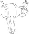
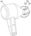
图1是本案一实施例的耳机装置的示意图;FIG. 1 is a schematic diagram of an earphone device according to an embodiment of the present case;
图2是图1的耳塞的立体透视图;Figure 2 is a perspective view of the earplug of Figure 1;
图3是图2的耳塞的剖视图;Fig. 3 is a sectional view of the earplug of Fig. 2;
图4A至图4D示出图1的耳塞变形;4A to 4D illustrate deformations of the earplug of FIG. 1;
图5A至图5C是图1的耳机装置的配戴流程图。5A to 5C are flowcharts of wearing the earphone device in FIG. 1 .
具体实施方式Detailed ways
现将详细地参考本案的示范性实施例,示范性实施例的实例说明于附图中。只要有可能,相同元件符号在附图和描述中用来表示相同或相似部分。Reference will now be made in detail to the exemplary embodiments of the present application, examples of which are illustrated in the accompanying drawings. Wherever possible, the same reference numbers will be used in the drawings and description to refer to the same or like parts.
图1是本案一实施例的耳机装置的示意图。图2是图1的耳塞的立体透视图。图3是图2的耳塞的剖视图,其对应于图2的I-I线。请参考图1至图3,本实施例的耳机装置100包括耳机110及耳塞120。耳塞120包括内管部122及外缘部124。FIG. 1 is a schematic diagram of an earphone device according to an embodiment of the present invention. FIG. 2 is a perspective perspective view of the earplug of FIG. 1 . Fig. 3 is a cross-sectional view of the earplug of Fig. 2, which corresponds to line I-I of Fig. 2 . Please refer to FIG. 1 to FIG. 3 , the
内管部122具有相对的第一端122a及第二端122b,第一端122a适于连接于耳机110,外缘部124具有相对的本案第一侧124a及本案第二侧124b,第一侧124a连接于内管部122的第二端122b,第二侧124b朝向第一端122a的方向延伸,而使外缘部124围绕内管部122b。The
一实施例中,内管部122与外缘部124例如是一体成形地相连接结构,其材质例如是硅胶或其他弹性材质。内管部122包括弹性曲折结构1221而具有较佳的弹性变形能力。In one embodiment, the
图4A至图4D示出图1的耳塞变形。通过内管部122的弹性曲折结构1221提供的良好弹性变形能力,内管部122可如图4A所示进行拉伸变形,如图4B所示进行压缩变形,如图4C所示进行向下转向变形,如图4D所示进行向上转向变形,或进行其他方向的转向变形。4A to 4D illustrate variations of the earplug of FIG. 1 . Through the good elastic deformation ability provided by the
图5A至图5C是图1的耳机装置的配戴流程图。当使用者如图5A至图5B所示将耳机110及连接于耳机110的耳塞120塞入耳道50时,内管部122的弹性弯折结构1221(标示于图2及图3)可藉其拉伸、溃缩和/或转向等类型的弹性变形而适应耳道50的延伸角度并贴靠于耳道50内壁。5A to 5C are flowcharts of wearing the earphone device in FIG. 1 . When the user inserts the
由于耳道50内的弹性弯折结构1221会因用户的手的施力而如图5B所示产生溃缩量,从而当使用者的手放开耳机110而使耳塞120被释放时,该溃缩量转化为弹性回复力而使耳塞120如图5C所示在耳道50内产生往外的适度位移量而自然调整为最舒适无异物感的状态。Since the
请参考图3,一实施例中,弹性曲折结构1221包括第一区段1221a、第二区段1221b及第三区段1221c。第三区段1221c、第一区段1221a及第二区段1221b沿内管部122的轴向A依序相连接。亦即,第一区段1221a沿内管部122的轴向A连接于第二区段1221b与第三区段1221c之间。Please refer to FIG. 3 , in one embodiment, the elastic
一实施例中,第一区段1221a的外径d1小于第二区段1221b的外径d2且小于第三区段1221c的外径d3,而使内管部122具有颈缩部N,据以构成弹性曲折结构1221。在其他实施例中,颈缩部N的数量可为多个,且弹性曲折结构1221可为其他适当形状,本案不对此加以限制。In one embodiment, the outer diameter d1 of the
如图3所示,一实施例中,内管部122在第一区段1221a的壁厚、内管部122在第二区段1221b的壁厚及内管部122在第三区段1221c的壁厚相同。亦即,弹性曲折结构1221具有均匀的壁厚,而可藉足够的结构强度提供良好的配戴支撑性。As shown in Figure 3, in one embodiment, the wall thickness of the
一实施例中,内管部122在其第一端122a处包括套接区段1222,套接区段1222连接于耳机110,而弹性曲折结构1221连接于套接区段1222与外缘部124之间。此外。在内管部122的轴向A上,外缘部124的延伸长度L1例如大于内管部122的长度L2,使外缘部124有足够的面积接触耳道50的内壁。In one embodiment, the
综上,在本案的耳塞中,内管部包含弹性弯折结构而具有较佳的弹性变形能力。藉此,当使用者将耳机及连接于耳机的耳塞塞入耳道时,弹性弯折结构可藉其拉伸、溃缩和/或转向等类型的弹性变形而适应各种不同耳道的延伸角度并贴靠于耳道内壁。并且,由于耳道内的弹性弯折结构会因用户的手的施力而产生溃缩量,从而当使用者的手放开耳机而使耳塞被释放时,该溃缩量转化为弹性回复力而使耳塞在耳道内产生往外的适度位移量而自然调整为最舒适无异物感的状态,且同时维持气密性及支撑性。To sum up, in the earplug of this case, the inner tube part includes an elastic bending structure and has better elastic deformation capability. In this way, when the user puts the earphone and the earplug connected to the earphone into the ear canal, the elastic bending structure can adapt to various extension angles of the ear canal through elastic deformation such as stretching, collapse, and/or turning. And stick to the inner wall of the ear canal. Moreover, since the elastic bending structure in the ear canal will produce a shrinkage due to the force applied by the user's hand, when the user's hand releases the earphone to release the earplug, the shrinkage is converted into elastic recovery force and Make the earplugs produce a moderate displacement in the ear canal and adjust them naturally to the most comfortable state without foreign body feeling, while maintaining airtightness and support at the same time.
最后应说明的是:以上各实施例仅用以说明本案的技术方案,而非对其限制;尽管参照前述各实施例对本案进行了详细的说明,本领域的普通技术人员应当理解:其依然可以对前述各实施例所记载的技术方案进行修改,或者对其中部分或者全部技术特征进行等同替换;而这些修改或者替换,并不使相应技术方案的本质脱离本案各实施例技术方案的范围。Finally, it should be noted that: the above embodiments are only used to illustrate the technical solution of the present case, rather than limit it; although the present case has been described in detail with reference to the foregoing embodiments, those of ordinary skill in the art should understand that: it still The technical solutions described in the above-mentioned embodiments can be modified, or some or all of the technical features can be equivalently replaced; and these modifications or replacements do not make the essence of the corresponding technical solutions depart from the scope of the technical solutions of the embodiments of the present case.
Claims (9)
Priority Applications (1)
| Application Number | Priority Date | Filing Date | Title |
|---|---|---|---|
| CN202110880690.4ACN115701719A (en) | 2021-08-02 | 2021-08-02 | Earbuds and Headphone Devices |
Applications Claiming Priority (1)
| Application Number | Priority Date | Filing Date | Title |
|---|---|---|---|
| CN202110880690.4ACN115701719A (en) | 2021-08-02 | 2021-08-02 | Earbuds and Headphone Devices |
Publications (1)
| Publication Number | Publication Date |
|---|---|
| CN115701719Atrue CN115701719A (en) | 2023-02-10 |
Family
ID=85142412
Family Applications (1)
| Application Number | Title | Priority Date | Filing Date |
|---|---|---|---|
| CN202110880690.4APendingCN115701719A (en) | 2021-08-02 | 2021-08-02 | Earbuds and Headphone Devices |
Country Status (1)
| Country | Link |
|---|---|
| CN (1) | CN115701719A (en) |
Citations (3)
| Publication number | Priority date | Publication date | Assignee | Title |
|---|---|---|---|---|
| CN102917291A (en)* | 2011-08-05 | 2013-02-06 | 譁懋国际有限公司 | Improved structure of earplug cushion body of earphone |
| CN207531026U (en)* | 2017-01-17 | 2018-06-22 | 好立威有限公司 | Earplug |
| CN215499510U (en)* | 2021-08-02 | 2022-01-11 | 华硕电脑股份有限公司 | Earplug and earphone device |
- 2021
- 2021-08-02CNCN202110880690.4Apatent/CN115701719A/enactivePending
Patent Citations (3)
| Publication number | Priority date | Publication date | Assignee | Title |
|---|---|---|---|---|
| CN102917291A (en)* | 2011-08-05 | 2013-02-06 | 譁懋国际有限公司 | Improved structure of earplug cushion body of earphone |
| CN207531026U (en)* | 2017-01-17 | 2018-06-22 | 好立威有限公司 | Earplug |
| CN215499510U (en)* | 2021-08-02 | 2022-01-11 | 华硕电脑股份有限公司 | Earplug and earphone device |
Similar Documents
| Publication | Publication Date | Title |
|---|---|---|
| JP6644858B2 (en) | Earpiece positioning and holding structure | |
| US8413663B2 (en) | Push-in type of earplug with improved insertion stem | |
| CN107079211B (en) | Holding structure for earpiece | |
| AU2004216223B2 (en) | Conforming earplug | |
| JP5934358B2 (en) | Earpiece passive noise attenuation | |
| US10820084B2 (en) | Ear tip sealing structure | |
| JP2022120049A (en) | Earphone and supporter | |
| CN215499510U (en) | Earplug and earphone device | |
| JP7634883B2 (en) | External ear attachment | |
| CN115701719A (en) | Earbuds and Headphone Devices | |
| EP4133747B1 (en) | Eartip, earphone, and method of manufacturing eartips for earphones | |
| CN211352407U (en) | Earplug with self-adaptation telescopic | |
| CN117546482A (en) | Earplugs for headphones | |
| JP6229536B2 (en) | Earphone manufacturing method and earphone | |
| TWI831019B (en) | In-ear headphone |
Legal Events
| Date | Code | Title | Description |
|---|---|---|---|
| PB01 | Publication | ||
| PB01 | Publication | ||
| SE01 | Entry into force of request for substantive examination | ||
| SE01 | Entry into force of request for substantive examination |