CN115697662A - Injection molding with variable volume recovery - Google Patents
Injection molding with variable volume recoveryDownload PDFInfo
- Publication number
- CN115697662A CN115697662ACN202080102104.7ACN202080102104ACN115697662ACN 115697662 ACN115697662 ACN 115697662ACN 202080102104 ACN202080102104 ACN 202080102104ACN 115697662 ACN115697662 ACN 115697662A
- Authority
- CN
- China
- Prior art keywords
- screw
- molten polymer
- mold cavity
- barrel
- injection molding
- Prior art date
- Legal status (The legal status is an assumption and is not a legal conclusion. Google has not performed a legal analysis and makes no representation as to the accuracy of the status listed.)
- Pending
Links
Images


Classifications
- B—PERFORMING OPERATIONS; TRANSPORTING
- B29—WORKING OF PLASTICS; WORKING OF SUBSTANCES IN A PLASTIC STATE IN GENERAL
- B29C—SHAPING OR JOINING OF PLASTICS; SHAPING OF MATERIAL IN A PLASTIC STATE, NOT OTHERWISE PROVIDED FOR; AFTER-TREATMENT OF THE SHAPED PRODUCTS, e.g. REPAIRING
- B29C45/00—Injection moulding, i.e. forcing the required volume of moulding material through a nozzle into a closed mould; Apparatus therefor
- B29C45/17—Component parts, details or accessories; Auxiliary operations
- B29C45/76—Measuring, controlling or regulating
- B29C45/762—Measuring, controlling or regulating the sequence of operations of an injection cycle
- B—PERFORMING OPERATIONS; TRANSPORTING
- B29—WORKING OF PLASTICS; WORKING OF SUBSTANCES IN A PLASTIC STATE IN GENERAL
- B29C—SHAPING OR JOINING OF PLASTICS; SHAPING OF MATERIAL IN A PLASTIC STATE, NOT OTHERWISE PROVIDED FOR; AFTER-TREATMENT OF THE SHAPED PRODUCTS, e.g. REPAIRING
- B29C45/00—Injection moulding, i.e. forcing the required volume of moulding material through a nozzle into a closed mould; Apparatus therefor
- B29C45/17—Component parts, details or accessories; Auxiliary operations
- B29C45/46—Means for plasticising or homogenising the moulding material or forcing it into the mould
- B29C45/461—Injection of measured doses
- B—PERFORMING OPERATIONS; TRANSPORTING
- B29—WORKING OF PLASTICS; WORKING OF SUBSTANCES IN A PLASTIC STATE IN GENERAL
- B29C—SHAPING OR JOINING OF PLASTICS; SHAPING OF MATERIAL IN A PLASTIC STATE, NOT OTHERWISE PROVIDED FOR; AFTER-TREATMENT OF THE SHAPED PRODUCTS, e.g. REPAIRING
- B29C45/00—Injection moulding, i.e. forcing the required volume of moulding material through a nozzle into a closed mould; Apparatus therefor
- B29C45/17—Component parts, details or accessories; Auxiliary operations
- B29C45/46—Means for plasticising or homogenising the moulding material or forcing it into the mould
- B29C45/47—Means for plasticising or homogenising the moulding material or forcing it into the mould using screws
- B—PERFORMING OPERATIONS; TRANSPORTING
- B29—WORKING OF PLASTICS; WORKING OF SUBSTANCES IN A PLASTIC STATE IN GENERAL
- B29C—SHAPING OR JOINING OF PLASTICS; SHAPING OF MATERIAL IN A PLASTIC STATE, NOT OTHERWISE PROVIDED FOR; AFTER-TREATMENT OF THE SHAPED PRODUCTS, e.g. REPAIRING
- B29C45/00—Injection moulding, i.e. forcing the required volume of moulding material through a nozzle into a closed mould; Apparatus therefor
- B29C45/17—Component parts, details or accessories; Auxiliary operations
- B29C45/76—Measuring, controlling or regulating
- B29C45/768—Detecting defective moulding conditions
- B—PERFORMING OPERATIONS; TRANSPORTING
- B29—WORKING OF PLASTICS; WORKING OF SUBSTANCES IN A PLASTIC STATE IN GENERAL
- B29C—SHAPING OR JOINING OF PLASTICS; SHAPING OF MATERIAL IN A PLASTIC STATE, NOT OTHERWISE PROVIDED FOR; AFTER-TREATMENT OF THE SHAPED PRODUCTS, e.g. REPAIRING
- B29C2945/00—Indexing scheme relating to injection moulding, i.e. forcing the required volume of moulding material through a nozzle into a closed mould
- B29C2945/76—Measuring, controlling or regulating
- B29C2945/76003—Measured parameter
- B29C2945/76083—Position
- B29C2945/7609—End position
- B—PERFORMING OPERATIONS; TRANSPORTING
- B29—WORKING OF PLASTICS; WORKING OF SUBSTANCES IN A PLASTIC STATE IN GENERAL
- B29C—SHAPING OR JOINING OF PLASTICS; SHAPING OF MATERIAL IN A PLASTIC STATE, NOT OTHERWISE PROVIDED FOR; AFTER-TREATMENT OF THE SHAPED PRODUCTS, e.g. REPAIRING
- B29C2945/00—Indexing scheme relating to injection moulding, i.e. forcing the required volume of moulding material through a nozzle into a closed mould
- B29C2945/76—Measuring, controlling or regulating
- B29C2945/76177—Location of measurement
- B29C2945/7618—Injection unit
- B29C2945/7619—Injection unit barrel
- B—PERFORMING OPERATIONS; TRANSPORTING
- B29—WORKING OF PLASTICS; WORKING OF SUBSTANCES IN A PLASTIC STATE IN GENERAL
- B29C—SHAPING OR JOINING OF PLASTICS; SHAPING OF MATERIAL IN A PLASTIC STATE, NOT OTHERWISE PROVIDED FOR; AFTER-TREATMENT OF THE SHAPED PRODUCTS, e.g. REPAIRING
- B29C2945/00—Indexing scheme relating to injection moulding, i.e. forcing the required volume of moulding material through a nozzle into a closed mould
- B29C2945/76—Measuring, controlling or regulating
- B29C2945/76494—Controlled parameter
- B29C2945/76648—Sequence, e.g. the order in which operations are conducted
- B—PERFORMING OPERATIONS; TRANSPORTING
- B29—WORKING OF PLASTICS; WORKING OF SUBSTANCES IN A PLASTIC STATE IN GENERAL
- B29C—SHAPING OR JOINING OF PLASTICS; SHAPING OF MATERIAL IN A PLASTIC STATE, NOT OTHERWISE PROVIDED FOR; AFTER-TREATMENT OF THE SHAPED PRODUCTS, e.g. REPAIRING
- B29C2945/00—Indexing scheme relating to injection moulding, i.e. forcing the required volume of moulding material through a nozzle into a closed mould
- B29C2945/76—Measuring, controlling or regulating
- B29C2945/76822—Phase or stage of control
- B29C2945/76846—Metering
Landscapes
- Engineering & Computer Science (AREA)
- Manufacturing & Machinery (AREA)
- Mechanical Engineering (AREA)
- Injection Moulding Of Plastics Or The Like (AREA)
- Moulds For Moulding Plastics Or The Like (AREA)
Abstract
Description
Translated fromChinese相关申请的交叉参考Cross References to Related Applications
本申请要求2020年6月15日提交的第63/039,344号美国临时申请的权益,所述美国临时申请的全文以引用的方式明确地并入本文中。This application claims the benefit of U.S. Provisional Application No. 63/039,344, filed June 15, 2020, which is expressly incorporated herein by reference in its entirety.
技术领域technical field
本公开大体上涉及注入模制,且更具体地说涉及用于使用可变体积恢复机制来控制注塑机的方法。The present disclosure relates generally to injection molding, and more particularly to methods for controlling injection molding machines using variable volume recovery mechanisms.
背景技术Background technique
注入模制是一种常用于大量制造由热塑性材料构成的零件的技术。在重复注入模制工艺期间,通常将小团粒或珠粒形式的热塑性树脂引入到注塑机中,注塑机在热和压力下使团粒熔融。在注入循环中,将熔融材料强力注入到具有特定所要腔形状的模腔中。注入的塑料在压力下保持在模腔中,并且随后冷却,然后作为凝固件被移除,所述凝固件具有非常类似于模具的腔形状的形状。单个模具可具有任何数目的个别腔,所述腔可以通过将熔融树脂流导入到腔中的浇口而连接到流通道。典型的注入模制程序通常包含四个基本操作:(1)在注塑机中加热塑料以允许塑料在压力下流动;(2)将熔融塑料注入到已关闭的两个半模之间限定的一个或多个模腔中;(3)在压力下允许塑料在所述一个或多个腔中冷却并硬化;以及(4)打开半模并从模具射出零件。Injection molding is a technique commonly used for the mass production of parts made of thermoplastic materials. During the repeated injection molding process, the thermoplastic resin is usually introduced in the form of small pellets or beads into an injection molding machine, which melts the pellets under heat and pressure. During the injection cycle, molten material is forcibly injected into a mold cavity having a specific desired cavity shape. The injected plastic is held in the mold cavity under pressure and is subsequently cooled before being removed as a solidified piece having a shape very similar to the cavity shape of the mold. A single mold may have any number of individual cavities that may be connected to flow channels by gates that direct the flow of molten resin into the cavities. A typical injection molding procedure usually consists of four basic operations: (1) heating the plastic in the injection molding machine to allow the plastic to flow under pressure; (3) allowing the plastic to cool and harden in the cavity or cavities under pressure; and (4) opening the mold halves and ejecting the part from the mold.
在常规系统中,在熔融塑料注入到一个或多个模腔中之后,将熔融塑料注入到一个或多个模腔中的装置(例如,螺杆或螺钻)进入恢复阶段,在恢复阶段,其在开始后续注入循环之前返回到原始位置。作为非限制性实例,此恢复过程可在从模具射出零件后开始。此恢复过程可能是耗时的且因此可能导致总循环效率低下。此外,在这些系统中,需要相当多的能量将螺杆推动到初始位置。相应地,螺杆在恢复阶段期间经历相当大的剪切力和其它力,这可能不利地影响螺杆的寿命。In conventional systems, after the molten plastic is injected into the one or more mold cavities, the device (for example, a screw or auger) that injects the molten plastic into the one or more mold cavities enters a recovery phase where its Return to the original position before starting subsequent injection cycles. As a non-limiting example, this recovery process may begin after the part has been ejected from the mold. This recovery process may be time consuming and thus may result in overall cycle inefficiency. Also, in these systems, considerable energy is required to drive the screw to the initial position. Accordingly, the screw experiences considerable shear and other forces during the recovery phase, which can adversely affect the life of the screw.
发明内容Contents of the invention
本发明的范围内的实施例是针对控制注塑机以产生可重复恒定的零件。用于控制具有形成模腔的模具且根据注入循环控制的注塑机的系统和方法包含:将熔融聚合物馈送到含有安置于第一位置中的螺杆的机筒中;第一次将螺杆从第一位置推进到第二位置,以将熔融聚合物注入到模腔中来形成模制零件;以及从模腔射出第一模制零件或第一组模制零件。此外,第二次将螺杆从第二位置推进到第三位置,以将熔融聚合物注入到模腔中来形成额外模制零件。从模腔射出第二模制零件或第二组模制零件。在第二次推进之后,开始恢复特征曲线,在所述恢复特征曲线中,螺杆返回到第一位置。Embodiments within the scope of the present invention are directed to controlling an injection molding machine to produce repeatable and constant parts. A system and method for controlling an injection molding machine having a mold forming a cavity and controlled according to an injection cycle comprising: feeding molten polymer into a barrel containing a screw positioned in a first position; first moving the screw from a first The position is advanced to a second position to inject molten polymer into the mold cavity to form a molded part; and eject a first molded part or a first set of molded parts from the mold cavity. Additionally, the screw is advanced a second time from the second position to the third position to inject molten polymer into the mold cavity to form additional molded parts. A second molded part or set of molded parts is ejected from the mold cavity. After the second advance, a recovery characteristic curve begins in which the screw returns to the first position.
在一些实例中,在螺杆从第一位置推进到第二位置之后开始保持模式。在一些实例中,所述方法可包含经由传感器确定安置于机筒内的熔融聚合物的感测到的体积,或确定安置于机筒内的熔融聚合物的感测到的体积的合适的指标。在一些实例中,传感器可呈螺杆位置传感器和/或熔体行程传感器的形式。In some examples, the hold mode begins after the screw advances from the first position to the second position. In some examples, the method may include determining, via a sensor, a sensed volume of molten polymer disposed within the barrel, or determining a suitable indicator of the sensed volume of molten polymer disposed within the barrel . In some examples, the sensors may be in the form of screw position sensors and/or melt stroke sensors.
将安置于机筒内的熔融聚合物的感测到的体积与同模腔相关联的填充体积进行比较。在这些实例中,仅当安置于机筒内的熔融聚合物的体积大于与模腔相关联的填充体积时才将螺杆从第二位置推进到第三位置。The sensed volume of molten polymer disposed within the barrel is compared to the fill volume associated with the cavity. In these examples, the screw is advanced from the second position to the third position only when the volume of molten polymer disposed within the barrel is greater than the fill volume associated with the mold cavity.
根据另一方面,一种注塑机包含注入单元,其具有形成模腔的模具和机筒;传感器,其与注入单元联接;控制器,其与注入单元和传感器联接。模腔具有填充体积。机筒含有可在机筒内移动的螺杆。所述注入单元适于接收熔融塑料材料并经由螺杆将其注入到模腔中以形成模制零件。传感器适于测量机筒中的熔融聚合物的至少一个特性。控制器适于根据注入循环控制注塑机的操作。此外,控制器适于将机筒的测得的特性与腔的填充体积进行比较。在机筒的测得的特性超出阈值后,控制器被配置成将螺杆从第一位置推进到第二位置,以将熔融聚合物注入到模腔中来形成第一模制零件或第一组模制零件。According to another aspect, an injection molding machine includes an injection unit having a mold and a barrel forming a mold cavity; a sensor coupled with the injection unit; and a controller coupled with the injection unit and the sensor. The mold cavity has a fill volume. The barrel contains a screw that moves within the barrel. The injection unit is adapted to receive molten plastic material and inject it into the mold cavity via a screw to form a molded part. The sensor is adapted to measure at least one characteristic of the molten polymer in the barrel. The controller is adapted to control the operation of the injection molding machine according to the injection cycle. Furthermore, the controller is adapted to compare the measured characteristic of the barrel with the fill volume of the cavity. After the measured characteristic of the barrel exceeds a threshold, the controller is configured to advance the screw from the first position to the second position to inject molten polymer into the mold cavity to form a first molded part or set of molded parts.
根据又一方面,一种非暂时性计算机可读存储介质适于存储处理器可执行指令,所述处理器可执行指令在执行时致使一个或多个处理器将熔融聚合物馈送到含有安置于第一位置中的螺杆的机筒中。此外,所述一个或多个处理器通过将信号传输到例如螺杆控制件等致动器而开始注入循环,所述致动器第一次将螺杆从第一位置推进到第二位置,以将熔融聚合物注入到模腔中来形成模制零件,从模腔射出第一模制零件或第一组模制零件,第二次将螺杆从第二位置推进到第三位置,以将熔融聚合物注入到模腔中来形成模制零件,从模腔射出第二模制零件或第二组模制零件,以及开始恢复特征曲线,在所述恢复特征曲线中,螺杆返回到第一位置。According to yet another aspect, a non-transitory computer-readable storage medium is adapted to store processor-executable instructions that, when executed, cause one or more processors to feed molten polymer to a In the barrel of the screw in the first position. Additionally, the one or more processors initiate an injection cycle by transmitting a signal to an actuator such as a screw control that first advances the screw from a first position to a second position to move the Molten polymer is injected into the mold cavity to form the molded part, the first molded part or first set of molded parts is ejected from the mold cavity, and the screw is advanced a second time from the second position to the third position to drive the molten polymer injecting material into the mold cavity to form a molded part, ejecting a second molded part or set of molded parts from the mold cavity, and initiating a recovery profile in which the screw returns to the first position.
根据另一方面,提供一种用于控制具有形成模腔的模具的注塑机的方法,其中根据注入循环来控制所述注塑机。所述方法包含将熔融聚合物馈送到含有螺杆的机筒中,以及通过推进螺杆将熔融聚合物的多个中间注料注入到模腔中。对于所述多个中间注料中的每一个,执行冷却步骤,借此熔融聚合物在模腔内冷却,且从模腔射出模制零件或一组模制零件。所述多个中间注料的冷却步骤和射出步骤之间没有能量消耗。通过推进螺杆将熔融聚合物的最终注料注入到模腔中,且执行最终冷却步骤和最终射出步骤。最终冷却步骤和最终射出步骤之间存在能量消耗。According to another aspect, a method is provided for controlling an injection molding machine having a mold forming a mold cavity, wherein the injection molding machine is controlled according to an injection cycle. The method includes feeding molten polymer into a barrel containing a screw, and injecting multiple intermediate shots of molten polymer into a mold cavity by advancing the screw. For each of the plurality of intermediate shots, a cooling step is performed whereby the molten polymer cools within the mold cavity and the molded part or group of molded parts is ejected from the mold cavity. There is no energy consumption between the cooling step and the injection step of the plurality of intermediate shots. A final shot of molten polymer is injected into the mold cavity by advancing the screw, and a final cooling step and a final injection step are performed. There is energy consumption between the final cooling step and the final injection step.
根据另一方面,提供一种用于控制具有形成模腔的模具的注塑机的方法,其中根据注入循环来控制所述注塑机。所述方法包含将熔融聚合物馈送到含有螺杆的机筒中,以及通过推进螺杆将熔融聚合物的多个连续注料注入到模腔中。注入循环的最高能量消耗值在注入到模腔中的熔融聚合物的所述多个连续注料的最终注料中发生。According to another aspect, a method is provided for controlling an injection molding machine having a mold forming a mold cavity, wherein the injection molding machine is controlled according to an injection cycle. The method comprises feeding molten polymer into a barrel containing a screw, and injecting a plurality of successive shots of the molten polymer into a mold cavity by advancing the screw. The highest energy consumption value of the injection cycle occurs in the final shot of said plurality of consecutive shots of molten polymer injected into the mold cavity.
附图说明Description of drawings
尽管本说明书通过特别指出并明确要求保护被视为本发明的主题的权利要求书作出结论,但相信通过以下结合附图的描述将更全面地理解本发明。一些图可能已经通过省略所选元件而经过简化,这是为了更清楚地展示其它元件。一些图中这样省略元件未必指示特定元件在任何示例性实施例中的存在或不存在,除非可能在相应文字描述中明确地如此叙述。图式均未必按比例绘制。举例来说,图中的一些元件的尺寸和/或相对定位可能相对于其它元件夸示以有助于改进对本发明的各种实施例的理解。While the specification concludes with claims particularly pointing out and distinctly claiming the subject matter which is regarded as the invention, it is believed that the invention will be more fully understood from the following description taken in conjunction with the accompanying drawings. Some of the figures may have been simplified by omitting selected elements in order to more clearly show other elements. Such omission of elements in some figures does not necessarily indicate the presence or absence of that particular element in any exemplary embodiment, unless expressly stated to be so in the corresponding written description. The drawings are not necessarily drawn to scale. For example, the size and/or relative positioning of some elements in the figures may be exaggerated relative to other elements to help to improve understanding of various embodiments of the present invention.
图1示出根据本公开的各种实施例的具有联接到其的控制器的实例第一注塑机的示意图;1 shows a schematic diagram of an example first injection molding machine with a controller coupled thereto, according to various embodiments of the present disclosure;
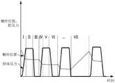
图2示出根据本公开的各种实施例的用于与注塑机一起使用的实例注入循环;2 illustrates an example injection cycle for use with an injection molding machine according to various embodiments of the present disclosure;
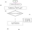
图3示出根据本公开的各种实施例的注塑机的可变体积恢复过程的实例流程图;3 illustrates an example flowchart of a variable volume recovery process for an injection molding machine according to various embodiments of the present disclosure;
图4示出根据常规方法的连续注入循环期间的实例能量消耗曲线图;Figure 4 shows a graph of example energy consumption during successive injection cycles according to a conventional method;
图5示出根据本公开的各种实施例的连续注入循环期间的实例能量消耗曲线图;FIG. 5 illustrates an example energy consumption graph during successive injection cycles according to various embodiments of the present disclosure;
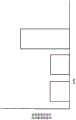
图6示出根据常规方法的连续注入循环期间的实例总能量消耗曲线图;以及Figure 6 shows a graph of example total energy consumption during successive injection cycles according to a conventional method; and
图7示出根据本公开的各种实施例的连续注入循环期间的实例总能量消耗曲线图。FIG. 7 illustrates an example total energy consumption graph during successive injection cycles according to various embodiments of the present disclosure.
具体实施方式Detailed ways
大体来说,本公开的各方面包含用于控制注塑机的系统和方法,其中调整操作参数以确保恒定熔融材料粘度下所注入塑料的恒定体积。在这些系统和方法中,在起始注入循环后,借此在第一注料中,将熔融塑料注入到模腔中,而非起始恢复特征曲线,在所述恢复特征曲线中,注塑机返回到原始位置,机器维持在“保持”位置中。在从模具射出第一模制零件或第一组模制零件之后,机器接着注入第二注料,借此额外熔融聚合物注入到模腔中以形成后续模制零件或后续组的模制零件。注塑机接着确定是否可在起始恢复特征曲线之前形成额外模制零件,且如果是,则继续注入第三注料和任何连续注料,借此额外熔融材料再次注入到模腔中以形成后续一个或多个模制零件。如果机器确定其无法在起始恢复之前形成额外模制零件,则机器接着起始恢复特征曲线,借此推进到原始位置。In general, aspects of the present disclosure include systems and methods for controlling an injection molding machine in which operating parameters are adjusted to ensure a constant volume of injected plastic at a constant molten material viscosity. In these systems and methods, after the initial injection cycle, whereby in the first shot, molten plastic is injected into the mold cavity, rather than an initial recovery profile in which the injection molding machine Returning to the original position, the machine remains in the "hold" position. After ejecting the first molded part or first set of molded parts from the mold, the machine then injects a second shot whereby additional molten polymer is injected into the mold cavity to form subsequent molded parts or sets of molded parts . The injection molding machine then determines whether additional molded parts can be formed prior to the initial recovery profile, and if so, proceeds to inject a third shot and any successive shots whereby additional molten material is reinjected into the cavity to form subsequent One or more molded parts. If the machine determines that it cannot form additional molded parts before initiating recovery, the machine then initiates a recovery profile, thereby advancing to the original position.
在一些实例中,注塑机首先计算(即,测量和/或感测)剩余待用于连续模制循环中的熔融聚合物的体积以确定是否可在起始恢复特征曲线之前执行连续循环。可经由任何数目的合适的传感器或感测机构执行此些计算。In some examples, the injection molding machine first calculates (ie, measures and/or senses) the volume of molten polymer remaining to be used in the continuous molding cycle to determine whether the continuous cycle can be performed before initiating the recovery profile. Such calculations may be performed via any number of suitable sensors or sensing mechanisms.
转向图式,本文描述注入模制工艺。本文中所描述的方法可适用于电动压机、伺服液压压机、液压压机和其它已知机器。如图1所示,注塑机100包含注入单元102和合模系统104。注入单元102包含料斗106,所述料斗适于接纳呈团粒108或任何其它适合的形式的材料。在许多这些实例中,团粒108可以是聚合物或基于聚合物的材料。其它实例是可能的。Turning to the drawings, the injection molding process is described herein. The methods described herein are applicable to electric presses, servo hydraulic presses, hydraulic presses, and other known machines. As shown in FIG. 1 , an
料斗106将团粒108馈送到注入单元102的受热机筒110中。在馈送到受热机筒110中后,团粒108可由往复螺杆112驱动到受热机筒110的端部,所述往复螺杆可从第一原始位置112a移动到若干后续位置以注入第一、第二、第三和/或任何后续注料。受热机筒110的加热和往复螺杆112对团粒108的压缩致使团粒108熔融,借此形成熔融塑料材料114。熔融塑料材料114通常在约130℃到约410℃的范围内选定的温度下进行加工(其中特定聚合物的制造商通常提供具有针对给定材料推荐的温度范围的注入模制器)。
在操作中,与注塑机110联接的控制器140通过以下操作开始注入循环:致使往复螺杆112从第一位置112a前向推进到第二位置112b以朝向喷嘴116推动熔融塑料材料114来形成塑料材料的第一注料,所述第一注料将最终经由将熔融塑料材料114流导引到模腔122的一个或多个浇口120注入到模具118的模腔122中。换句话说,往复螺杆112被驱动以对熔融塑料材料114施加力。在其它实施例中,喷嘴116可通过进料系统(未示出)与一个或多个浇口120分离。模腔122形成在模具118的第一和第二模具侧125、127之间,且第一和第二模具侧125、127在压力下经由压机或合模单元124固持在一起。模腔122具有与其相关联的填充体积。In operation,
在模制工艺期间,压机或合模单元124施加预定的合模力,所述预定的合模力大于由注入压力作用以使两个半模125、127分离所施加的力,由此在将熔融塑料材料114注入到模腔122中时使第一和第二模具侧125、127固持在一起。为了支持这些合模力,除了任何其它数目的例如连接杆等组件外,合模系统104还可包含模框和模座。During the molding process, the press or clamping
一旦熔融塑料材料114的第一注料被注入到模腔122中,往复螺杆112就停止向前移动。熔融塑料材料114采用模腔122的形式,且在模具118内部冷却,直到塑料材料114凝固。在凝固后,压机124释放第一和第二模具侧115、117,所述模具侧随后彼此分离。成品零件接着可从模具118射出。模具118可包含任何数目的模腔122,以增加总产率。腔的形状及/或设计可彼此相同、相似及/或不同。举例来说,系列模具可包含既定彼此配对或以其它方式一起操作的相关组成部分的腔。在一些形式中,“注入循环”被定义为在注入开始与射出之间执行的步骤及功能。Once the first shot of molten
如前文所述,注塑机100还包含经由连接145与机器100以通信方式联接的控制器140。连接145可以是适于传输和/或接收电子信号的任何类型的有线和/或无线通信协议。在这些实例中,控制器140与至少一个传感器(例如,位于喷嘴116中或附近的传感器128,及/或位于模腔122中或附近的传感器129)进行信号通信。在一些实例中,传感器128位于螺杆112的前端处,且传感器129位于注入机器100的歧管或流道中。或者,传感器128可位于螺杆112的锁环前的任何位置处。可使用能够感测模具118和/或机器100的任何数目的特性的任何数目的额外的真实和/或虚拟传感器,且将所述传感器放置于机器100的所要位置处。在一些实例中,传感器128可呈螺杆位置传感器或熔体行程传感器的形式。作为另一实例,可使用能够检测模腔122中的流动前沿进程的任何类型的传感器。As previously mentioned,
控制器140可以相对于注塑机100安置在若干位置中。作为实例,控制器140可与机器100形成为一个整体、含于安装在机器上的罩壳中、含于定位成邻近于或接近于机器的单独罩壳中,或可远离机器定位。在一些实施例中,控制器140可以经由如此项技术中已知和/或常用的有线和/或有线信号通信部分或完全地控制机器的功能。
传感器128可以是适于测量(直接或间接)熔融塑料材料114和/或机器100的部分(例如,机筒110和/或螺杆112)的一个或多个特性以确定机筒110中剩余的待用于后续注料的熔融塑料材料114的体积的任何类型的传感器。传感器128可能或可能不与熔融塑料材料114直接接触。Sensor 128 may be adapted to measure (directly or indirectly) one or more characteristics of molten
传感器128生成信号,所述信号被传输到控制器140的输入端。如果传感器128不位于喷嘴116内,则控制器140可被设定、配置和/或编程有逻辑、命令和/或可执行程序指令以提供适当校正因子来估计或计算测得的特性(即,机筒110内的熔融塑料材料114的剩余体积)的值。举例来说,如前文所述,传感器128可经编程以测量螺杆位置或熔体行程。The sensor 128 generates a signal, which is transmitted to an input of a
如果并入到注塑机100中,则传感器129可以是适于测量(直接或间接)熔融塑料材料114的一个或多个特性以检测其在模腔122中的存在和/或状况的任何类型的传感器。在各种实施例中,传感器129可位于模腔122中的填充结束位置处或附近。传感器129可测量此项技术中己知的熔融塑料材料114及/或模腔122的任何数目的特性,例如压力、温度、粘度、流率、硬度、应变、例如半透明性、颜色、光折射及/或光反射等光学特性,或指示这些特性的任何数目的额外特性中的任何一个或多个。传感器129可能或可能不与熔融塑料材料114直接接触。作为实例,传感器129可以是测量腔122内的熔融塑料材料114的腔压力的压力转换器。传感器129生成信号,所述信号被传输到控制器140的输入端。可使用任何数目的额外传感器来感测和/或测量操作参数。If incorporated into
控制器140还与螺杆控制件126进行信号通信。在一些实施例中,控制器140生成信号,所述信号从控制器140的输出端传输到螺杆控制件126。控制器140可控制机器的任何数目的特性,例如注入压力(通过控制螺杆控制件126来使螺杆112以维持对应于喷嘴116中的熔融塑料材料114的所要值的速率前进)、机筒温度、夹具关闭和/或打开速度、冷却时间、向前注入时间、总循环时间、压力设定点、射出时间、螺杆恢复速度、螺杆起始恢复的时间,和/或施加在螺杆112上的背压值。
来自控制器140的一个或多个信号可通常用于控制模制工艺的操作,使得控制器140考虑材料粘度、模具温度、熔体温度的变化以及影响填充速率的其它变化。作为替代或另外,控制器140可进行必要调整以控制例如体积和/或粘度等材料特性。可由控制器140实时或近实时地(即,在传感器128、129感测值和对工艺作出的改变之间具有最小延迟)作出调整,或可以在后续循环中作出校正。此外,可将从任何数目的个别循环导出的若干信号用作对模制工艺作出调整的基础。控制器140可经由此项技术中已知的任何类型的信号通信方法连接到传感器128、129、螺杆控制件126和/或机器100中的任何其它组件。One or more signals from
控制器140包含适于控制其操作的软件141、任何数目的硬件元件142(例如,非暂时性存储器模块和/或处理器)、任何数目的输入端143、任何数目的输出端144以及任何数目的连接145。软件141可以非暂时性计算机可读介质的形式直接加载到控制器140的非暂时性存储器模块上,或可替代地位于远离控制器140的位置并且可经由任何数目的控制方法与控制器140通信。软件141包含逻辑、命令和/或可执行程序指令,所述可执行程序指令可含有用于根据模制循环控制注塑机100的逻辑和/或命令。软件141可包含或可不包含操作系统、操作环境、应用环境和/或用户接口。
硬件142使用输入端143从由控制器140控制的注塑机接收信号、数据和信息。硬件142使用输出端144将信号、数据和/或其它信息发送到注塑机。连接145表示可以通过其在控制器140与其注塑机100之间传输信号、数据和信息的路径。在各种实施例中,此路径可以是物理连接或非物理通信链路,所述非物理通信链路类似于以本文中描述的或此项技术中已知的任何方式配置的直接或间接的物理连接工作。在各种实施例中,可以此项技术中已知的任何额外或替代方式来配置控制器140。
连接145表示可以通过其在控制器140与注塑机100之间传输信号、数据和信息的路径。在各种实施例中,这些路径可以是物理连接或非物理通信链路,所述非物理通信链路类似于以本文中描述的或此项技术中已知的任何方式配置的直接或间接物理连接工作。在各种实施例中,可以此项技术中已知的任何额外或替代方式来配置控制器140。
如图2中所示出,提供并入有可变体积恢复技术的实例注入模制循环,借此以实线描绘随时间的熔体压力,且以虚线描绘往复螺杆112随时间的纵向位置。在将熔融聚合物114馈送到机筒110中后且如图2的步骤“I”中所示出,往复螺杆112开始向前推进,借此开始注入第一注料,于是熔融塑料材料114被馈送到模腔122中。往复螺杆112的此推进致使熔体压力增加直至获得所要的稳态保持压力(如图2的步骤“II”中所示出)。此处,往复螺杆位于第二位置112b处(图1)。如图2中所示出,在一些实例中,往复螺杆112可继续缓慢向前推进以在此保持时间期间维持所要保持压力。模制零件在此时间期间冷却。As shown in FIG. 2 , an example injection molding cycle incorporating a variable volume recovery technique is provided whereby melt pressure over time is depicted in solid lines and longitudinal position of reciprocating
接下来,在步骤“III”处,模腔122打开(因此腔压力突然下降),且自其射出第一模制零件或第一组模制零件。如前所述,往复螺杆112维持在第二位置112b中,且尚未进入恢复特征曲线,在所述恢复特征曲线中,其返回到第一位置112a。如下文将论述,在一些实例中,机器100可确定是否有足够的熔融聚合物114留在机筒110内以进行到步骤“IV”,在该步骤中,模腔关闭,且控制器140开始第二注入循环。如同步骤I,在此步骤中,往复螺杆112再次向前推进以开始注入第二注料,于是熔融塑料材料114被馈送到模腔122中。如前所述,往复螺杆112的此推进致使熔体压力增加直至获得所要的稳态保持压力(如图2的步骤“V”中所示出)。此处,往复螺杆位于第三位置112c处(图1)。如先前描述,在一些实例中,往复螺杆112可继续缓慢向前推进以在此保持时间期间维持所要保持压力。模制零件在此时间期间冷却。Next, at step "III," the mold cavity 122 is opened (thus a sudden drop in cavity pressure), and the first molded part or set of molded parts is ejected therefrom. As before, the
再次,在步骤“VI”处,模腔122打开,且自其射出第二模制零件或第二组模制零件。在所示出的实例中,在第二注入循环完成后,控制器140开始恢复特征曲线,在此期间,往复螺杆112返回到初始第一位置112a,于是可以新的熔融聚合物114执行后续注入循环。在一些实例中,恢复特征曲线可在冷却阶段期间发生。如下文将更详细地描述,在一些实例中,控制器140可取决于安置于机筒110内的熔融聚合物114的总体积致使往复螺杆112推进额外次数以完成第三、第四、第五、第六或更多个额外注料,借此熔融聚合物114被注入到模腔122中。Again, at step "VI," mold cavity 122 is opened, and a second molded part or set of molded parts is ejected therefrom. In the example shown, after the second injection cycle is complete, the
应了解,在一些实例中,可在这些步骤中的任一个(例如,注入、模具打开/关闭和/或恢复)期间选择性地调整注入压力。更确切地说,在模具打开/零件射出步骤期间,压力可减小,同时往复螺杆112维持其位置。It should be appreciated that, in some examples, injection pressure may be selectively adjusted during any of these steps (eg, injection, mold opening/closing, and/or recovery). More specifically, during the mold open/part injection step, the pressure may be reduced while the
在一些实例中,控制器140和传感器128可协作以确定感测到的特性(例如,机筒110内的熔融聚合物114的数量或体积)。可通过确定螺杆的位置和/或熔融聚合物114的熔体行程来执行此计算。其它合适的方法是可能的。在一些实例中,在开始第一注入循环之前,控制器140和传感器128可自动确定安置于机筒110内的熔融聚合物114的数量或体积或者此数量或体积的合适的指标,例如螺杆位置或机筒内的熔体压力,且将此值与一个或多个模腔122的总体积进行比较。作为非限制性实例,一个或多个模腔122的总体积可近似为1-1,000克,且安置于机筒110内的熔融聚合物114的内部体积可近似为10-5,000克。在一些实例中,可经由传感器(例如,传感器129)计算一个或多个模腔122的总体积,且在其它实例中,此总体积可在初始化过程期间提供到控制器140。在确定这些体积后,控制器140可执行可在耗尽安置于机筒110内的可用的熔融聚合物114之前执行的连续注料的数目的预备计算。在此实例中,机筒110含有足够的熔融聚合物114以执行五个连续注料,而不需要返回到第一位置112a并起始恢复特征曲线。In some examples,
作为额外非限制性实例,如果每一注料需要安置于机筒110内的熔融聚合物114的体积的大致20%,则机器100可能够在进入恢复特征曲线之前执行五个连续注料。然而,在一些实例中,可实施“阈值”、“缓冲区”或“缓冲”以确保足够的熔融聚合物114留在机筒内。举例来说,控制器140可考虑超出一个或多个模腔122的总体积的大致5%与大致15%之间的缓冲区。相应地,在这些实例中,控制器140还可能需要在执行注料之前在机筒110中存在除一个或多个模腔122中的体积外的缓冲区值。相应地,在其中每一注料需要安置于机筒110内的熔融聚合物114的体积的大致20%的以上实例中,控制器可仅允许在起始恢复特征曲线之前完成四个连续注料以便考虑5-15%缓冲区。其它实例是可能的。As an additional non-limiting example, if each shot requires approximately 20% of the volume of
在一些方法中,控制器140和传感器128可协作以执行可用的熔融聚合物114的“运行中”计算。更确切地说,在机器100执行第一注料后,控制器140可致使传感器128确定安置于机筒110内的熔融聚合物114的剩余体积。控制器140可接着确定此剩余体积是否大于一个或多个模腔122的总填充体积(加上任何额外所要缓冲区值),且如果是,则控制器140可接着致使往复螺杆112前进以将熔融聚合物114的额外注料注入到模腔122中。注入熔融聚合物114的额外注料的过程可继续直至控制器140确定没有足够的熔融聚合物114留在机筒110内来执行后续注料为止。在一些实例中,控制器140可另外确认螺杆122是否具有足够的行进长度以将熔融聚合物114的后续注料注入到模腔122中。其它实例是可能的。In some approaches,
在完成这些注入循环后(以及在一些实例中,在确定已经运行所要数目次注料或机筒110中的熔融聚合物114的剩余体积不足以完成另一次注料后),开始恢复特征曲线(图2的步骤“VII”),其中往复螺杆112返回到第一位置112a。此时,控制器可执行机筒110内的可用的熔融聚合物114的额外比较,或可仅仅归因于机筒110内将存在足够的熔融聚合物114来执行第一注料的假设而开始第一循环。然而,在一些环境中,可能需要在注入第一注料之前并入所述比较以充当故障保护来确保熔融聚合物114成功地进入机筒110。After completing these injection cycles (and in some instances, after determining that the desired number of shots have been run or that the remaining volume of
如图3中所示出,描述实例可变体积恢复过程300。首先,在步骤302处,将熔融聚合物114馈送到机筒110中。在步骤304处,推进往复螺杆112以将熔融聚合物114的注料注入到模腔122中。在步骤306处,控制器140使用来自传感器128的感测到的值确定机筒110内剩余的熔融聚合物114是否足以填充模腔122。如果安置于机筒110内的剩余熔融聚合物114足以填充模腔122,则过程300进行到步骤308,其中往复螺杆112再次推进到后续位置以注入熔融聚合物的额外注料。过程300接着返回到步骤306,其中控制器140使用来自传感器128的感测到的值确定机筒110内剩余的熔融聚合物114是否足以填充模腔122。如果在步骤306处剩余的熔融聚合物114不足以填充模腔122,则过程300前进到步骤310,借此起始致使往复螺杆112返回到第一位置的恢复特征曲线。过程300接着进行到步骤302,其中将熔融聚合物114馈送到机筒110中。As shown in FIG. 3 , an example variable
通过并入可变体积恢复过程,机器100可在延长的周期内使用比常规注塑机明显更少的能量。更确切地说,当将可变体积恢复过程下的熔融聚合物的10个注料与常规恢复方法下的熔融聚合物的10个注料进行比较时,归因于往复螺杆112返回到初始位置112a的次数少于需要往复螺杆在每一次注料之后都返回到初始位置的常规工艺,能量大大减少。因此,总体能量消耗较少。参考图4和5,其中螺杆在每一连续注料之后恢复(图4)的常规注入模制工艺需要比由图5表示的系统明显更多的能量,在由图5表示的系统中,在第一注料之后,机器经历完全螺杆恢复,但在三个后续注料中不恢复。在如此配置的情况下,在所示出的实例中,本文中所描述的可变体积恢复过程可使用利用常规方法执行三个注入循环所需的相同量的能量来注入四个注入循环。应了解,例如机器大小(吨位)和类型(例如,液压、混合式、电动等)各种因素可能影响可使用可变体积恢复执行的相当的循环的数目相对于常规恢复方法的比率。By incorporating a variable volume recovery process, the
参考图6和7,提供多个注料(例如,三个连续注料)的实例总能量消耗曲线图。如图6中所示出,在常规方法中,连续注料的总能量使用归因于螺杆在每一次注料之后恢复而为大致恒定的。然而,在使用本文中所描述的实例可变体积恢复过程的图7所示出的实例中,所述多个连续注料的最高能量消耗值在所述多个连续注料中的最后一个中发生。相应地,可变体积恢复过程在螺杆不恢复的情况下使用每注料较少能量,但总能量消耗也少于常规恢复方法。Referring to Figures 6 and 7, example total energy consumption graphs for multiple shots (eg, three consecutive shots) are provided. As shown in Figure 6, in the conventional process, the total energy usage for continuous injection is approximately constant due to screw recovery after each injection. However, in the example shown in Figure 7 using the example variable volume recovery process described herein, the highest energy consumption value for the plurality of successive shots is in the last of the plurality of successive shots occur. Correspondingly, the variable volume recovery process uses less energy per shot without screw recovery, but the overall energy consumption is also less than conventional recovery methods.
此外,在一些环境中,本文中所描述的可变体积恢复过程可实现时间节省。在其中往复螺杆花费比其使零件冷却和射出零件所花费时间更多的时间恢复的系统中,使用本文中所描述的可变体积恢复过程将实现循环时间节省,因为机器不必等待螺杆恢复才注入后续注料。实际上,本文中所描述的可变体积恢复过程允许紧接在模制零件冷却并从模腔122射出(且模腔122再次关闭)之后注入后续注料。通过不需要往复螺杆114每隔三个到六个循环斜升和斜降到一个注入循环,所述过程总体上需要更少的时间。此系统对于其中恢复时间长于必需的射出前冷却时间的模制操作可能特别有益,使得恢复操作有效地控制循环时间的变化。Furthermore, in some circumstances, the variable volume restoration process described herein can achieve time savings. In systems where the reciprocating screw spends more time recovering than it does cooling and ejecting the part, using the variable volume recovery process described in this article will realize cycle time savings because the machine does not have to wait for the screw to recover before injecting Subsequent injection. In effect, the variable volume recovery process described herein allows subsequent shots to be injected immediately after the molded part has cooled and been ejected from the mold cavity 122 (and the mold cavity 122 closed again). The process takes less time overall by not requiring the
应了解,任何数目的替代性特征和/或方法可并入到可变体积恢复过程中。举例来说,在一些方法中,控制器140可被配置成在机器100经历关机作为安全措施之后自动致使往复螺杆112恢复到第一位置112。此外,在一些实例中,控制器可知晓可在多部件模具中制造多少个零件,且可能够推进螺杆以在机筒110中剩余的熔融聚合物不足以完全填充每一模腔的情况下模制出特定数目的零件。在此些实例中,本文中所描述的方法可用于更充分利用安置于机筒内的熔融塑料材料和/或更准确地填充所要生产轮次。其它实例是可能的。It should be appreciated that any number of alternative features and/or methods may be incorporated into the variable volume recovery process. For example, in some approaches, the
在一些方法中,注塑机可注入不同体积的注料。举例来说,在其中模具可动态地关闭所要数目的模腔的注塑机中,机器可确定打开的模腔的填充体积且注入具有相应体积的熔融塑料材料的注料。此外,在其中组件(即,锁环)可能正展现功能失常的实例中,螺杆可能需要行进不同长度以便补偿此功能失常。此外,在一些实例中,有可能例如立方体模具等模具针对立方体的每一相应面具有不同的腔和零件布局,这可能使得有必要取决于哪一模具面为现用而需要可变体积的材料。其它实例是可能的。In some methods, the injection molding machine can inject different volume shots. For example, in an injection molding machine where a mold can dynamically close a desired number of cavities, the machine can determine the fill volume of the open cavities and inject a shot with a corresponding volume of molten plastic material. Furthermore, in instances where a component (ie, lock ring) may be exhibiting malfunction, the screw may need to travel a different length in order to compensate for this malfunction. Furthermore, in some instances it is possible that a mold such as a cube mold has a different cavity and part layout for each respective face of the cube, which may necessitate variable volumes of material depending on which mold face is active . Other examples are possible.
本文中所描述的可变体积恢复过程可有利地并入到常规注入模制系统、并入有较低大体上恒定压力方法的注入模制系统,和任何其它系统中。The variable volume recovery process described herein can be advantageously incorporated into conventional injection molding systems, injection molding systems incorporating lower substantially constant pressure methods, and any other system.
在如此配置的情况下,可变体积恢复过程实现能量和时间节省两者。此外,归因于减少往复螺杆必须返回到其初始位置的次数,可变体积恢复过程使得对往复螺杆的磨损较小。即使在使用电动注塑机的系统中,归因于较长时间内经历较少循环,伺服马达的寿命可延长,这对于具有较短持续时间的增加数目的循环是优选的,因为开始起始恢复特征曲线所需的惯性通常是对马达最大的耗费之一。So configured, the variable volume recovery process achieves both energy and time savings. Furthermore, the variable volume recovery process results in less wear on the reciprocating screw due to reducing the number of times the reciprocating screw must return to its original position. Even in systems using electric injection molding machines, the life of the servo motor can be extended due to the fact that fewer cycles are experienced over a longer period of time, which is preferred for an increased number of cycles with a shorter duration, as initial recovery begins The inertia required for the characteristic curve is usually one of the greatest costs to the motor.
虽然本文描述热塑性塑料注入模制工艺,但应了解,本公开中的实施例还可涉及其它注入模制工艺,例如金属注入模制(MIM)、反应注入模制(RIM)、液体注入模制(LIM)、结构泡沫成型,以及液晶聚合物(LCP)模制。其它实例是可能的。Although thermoplastic injection molding processes are described herein, it should be understood that embodiments in the present disclosure may also relate to other injection molding processes, such as metal injection molding (MIM), reaction injection molding (RIM), liquid injection molding (LIM), structural foam molding, and liquid crystal polymer (LCP) molding. Other examples are possible.
所属领域的技术人员将认识到,在不脱离本发明的范围的情况下,可相对于上述实施例作出多种多样的修改、更改和组合,并且此类修改、更改和组合应视为在本发明概念的范围内。Those skilled in the art will appreciate that various modifications, changes and combinations can be made with respect to the above-described embodiments without departing from the scope of the present invention, and such modifications, changes and combinations should be considered as included in the present invention. within the scope of the inventive concept.
本专利申请的末尾的专利权利要求书并不希望根据35U.S.C.§112(f)进行解释,除非明确地叙述了传统的手段加功能(means-plus-function)措辞,例如在权利要求中明确地叙述“用于……的构件”或“用于……的步骤”这样的措辞。本文中所描述的系统和方法是针对对计算机功能性的改进,并改进常规计算机的运行。The patent claims at the end of this patent application are not intended to be construed under 35 U.S.C. §112(f) unless the conventional means-plus-function language is expressly recited, such as in the claims Describe phrases such as "means for" or "steps for" appropriately. The systems and methods described herein are directed to improving the functionality of computers and improving the operation of conventional computers.
Claims (21)
Applications Claiming Priority (3)
| Application Number | Priority Date | Filing Date | Title |
|---|---|---|---|
| US202063039344P | 2020-06-15 | 2020-06-15 | |
| US63/039,344 | 2020-06-15 | ||
| PCT/US2020/066415WO2021257116A1 (en) | 2020-06-15 | 2020-12-21 | Injection molding having variable volume recovery |
Publications (1)
| Publication Number | Publication Date |
|---|---|
| CN115697662Atrue CN115697662A (en) | 2023-02-03 |
Family
ID=78826404
Family Applications (1)
| Application Number | Title | Priority Date | Filing Date |
|---|---|---|---|
| CN202080102104.7APendingCN115697662A (en) | 2020-06-15 | 2020-12-21 | Injection molding with variable volume recovery |
Country Status (6)
| Country | Link |
|---|---|
| US (1) | US20210387390A1 (en) |
| EP (1) | EP4164853A1 (en) |
| JP (1) | JP2023530124A (en) |
| CN (1) | CN115697662A (en) |
| CA (1) | CA3186127A1 (en) |
| WO (1) | WO2021257116A1 (en) |
Citations (7)
| Publication number | Priority date | Publication date | Assignee | Title |
|---|---|---|---|---|
| DE1926032A1 (en)* | 1969-05-22 | 1970-11-26 | Drabert Soehne | Thermosetting plastics extruder |
| US4256689A (en)* | 1975-10-31 | 1981-03-17 | Gardner Victor T | Injection moulding method and apparatus with mould runner reservoir and shot extension |
| AT3800U1 (en)* | 1999-07-09 | 2000-08-25 | Engel Gmbh Maschbau | INJECTION MOLDING METHOD |
| CN101157266A (en)* | 2007-11-08 | 2008-04-09 | 东华机械有限公司 | High-speed injection molding, energy storage and pressure maintaining injection molding method |
| CN103753782A (en)* | 2014-01-20 | 2014-04-30 | 无锡华宇精密机械有限公司 | Plastification device |
| CN105228804A (en)* | 2013-05-13 | 2016-01-06 | 宝洁公司 | Low constant pressure injection molding system with variable cavity position |
| US20200078999A1 (en)* | 2018-09-07 | 2020-03-12 | iMFLUX Inc. | Systems and approaches for controlling an injection molding machine |
Family Cites Families (4)
| Publication number | Priority date | Publication date | Assignee | Title |
|---|---|---|---|---|
| US3642402A (en)* | 1970-03-10 | 1972-02-15 | Pennwalt Corp | Injection molding process control |
| US20080093772A1 (en)* | 2006-10-06 | 2008-04-24 | Graham Packing Company, Lp | Method and apparatus for delivering sequential shots to multiple cavities to form multilayer articles |
| TWI391229B (en)* | 2008-10-09 | 2013-04-01 | Mitsubishi Heavy Ind Plastic T | Injection molding machine and injection molding |
| EP3317074B1 (en)* | 2015-06-30 | 2020-02-19 | Imflux Inc. | Sequential coining |
- 2020
- 2020-12-21EPEP20940535.6Apatent/EP4164853A1/ennot_activeWithdrawn
- 2020-12-21WOPCT/US2020/066415patent/WO2021257116A1/ennot_activeCeased
- 2020-12-21JPJP2022577083Apatent/JP2023530124A/ennot_activeWithdrawn
- 2020-12-21CACA3186127Apatent/CA3186127A1/enactivePending
- 2020-12-21CNCN202080102104.7Apatent/CN115697662A/enactivePending
- 2021
- 2021-05-21USUS17/326,597patent/US20210387390A1/ennot_activeAbandoned
Patent Citations (7)
| Publication number | Priority date | Publication date | Assignee | Title |
|---|---|---|---|---|
| DE1926032A1 (en)* | 1969-05-22 | 1970-11-26 | Drabert Soehne | Thermosetting plastics extruder |
| US4256689A (en)* | 1975-10-31 | 1981-03-17 | Gardner Victor T | Injection moulding method and apparatus with mould runner reservoir and shot extension |
| AT3800U1 (en)* | 1999-07-09 | 2000-08-25 | Engel Gmbh Maschbau | INJECTION MOLDING METHOD |
| CN101157266A (en)* | 2007-11-08 | 2008-04-09 | 东华机械有限公司 | High-speed injection molding, energy storage and pressure maintaining injection molding method |
| CN105228804A (en)* | 2013-05-13 | 2016-01-06 | 宝洁公司 | Low constant pressure injection molding system with variable cavity position |
| CN103753782A (en)* | 2014-01-20 | 2014-04-30 | 无锡华宇精密机械有限公司 | Plastification device |
| US20200078999A1 (en)* | 2018-09-07 | 2020-03-12 | iMFLUX Inc. | Systems and approaches for controlling an injection molding machine |
Also Published As
| Publication number | Publication date |
|---|---|
| US20210387390A1 (en) | 2021-12-16 |
| WO2021257116A1 (en) | 2021-12-23 |
| JP2023530124A (en) | 2023-07-13 |
| CA3186127A1 (en) | 2021-12-23 |
| EP4164853A1 (en) | 2023-04-19 |
Similar Documents
| Publication | Publication Date | Title |
|---|---|---|
| US11642821B2 (en) | Expanding crosslinking polymer injection molding system | |
| EP3846996B1 (en) | Closed loop control for injection molding processes | |
| US20200086542A1 (en) | Methods for controlling injection molding processes based on actual plastic melt pressure or cavity pressure | |
| US20220024098A1 (en) | Injection molding of crosslinking polymers | |
| EP3846997B1 (en) | Systems and approaches for controlling an injection molding machine | |
| US20150140148A1 (en) | Controller for injection molding machine | |
| JP6791948B2 (en) | Injection molding machine | |
| JP6385831B2 (en) | Injection molding machine | |
| US20180361643A1 (en) | Injection Molding of Crosslinking Polymers | |
| JP5011050B2 (en) | Injection molding method | |
| CN115697662A (en) | Injection molding with variable volume recovery | |
| JP6552933B2 (en) | Injection molding machine | |
| US20210387391A1 (en) | Independent startup mode for injection molding | |
| JP4085103B2 (en) | Holding pressure switching control method | |
| JP2001300997A (en) | Method and apparatus for injection molding | |
| JP4502669B2 (en) | Injection molding machine and control method thereof |
Legal Events
| Date | Code | Title | Description |
|---|---|---|---|
| PB01 | Publication | ||
| PB01 | Publication | ||
| SE01 | Entry into force of request for substantive examination | ||
| SE01 | Entry into force of request for substantive examination |