CN115697255A - Expandable devices and related systems and methods - Google Patents
Expandable devices and related systems and methodsDownload PDFInfo
- Publication number
- CN115697255A CN115697255ACN202180023798.XACN202180023798ACN115697255ACN 115697255 ACN115697255 ACN 115697255ACN 202180023798 ACN202180023798 ACN 202180023798ACN 115697255 ACN115697255 ACN 115697255A
- Authority
- CN
- China
- Prior art keywords
- stent
- strut
- expandable
- spine
- expandable apparatus
- Prior art date
- Legal status (The legal status is an assumption and is not a legal conclusion. Google has not performed a legal analysis and makes no representation as to the accuracy of the status listed.)
- Pending
Links
Images


Classifications
- A—HUMAN NECESSITIES
- A61—MEDICAL OR VETERINARY SCIENCE; HYGIENE
- A61F—FILTERS IMPLANTABLE INTO BLOOD VESSELS; PROSTHESES; DEVICES PROVIDING PATENCY TO, OR PREVENTING COLLAPSING OF, TUBULAR STRUCTURES OF THE BODY, e.g. STENTS; ORTHOPAEDIC, NURSING OR CONTRACEPTIVE DEVICES; FOMENTATION; TREATMENT OR PROTECTION OF EYES OR EARS; BANDAGES, DRESSINGS OR ABSORBENT PADS; FIRST-AID KITS
- A61F2/00—Filters implantable into blood vessels; Prostheses, i.e. artificial substitutes or replacements for parts of the body; Appliances for connecting them with the body; Devices providing patency to, or preventing collapsing of, tubular structures of the body, e.g. stents
- A61F2/82—Devices providing patency to, or preventing collapsing of, tubular structures of the body, e.g. stents
- A61F2/86—Stents in a form characterised by the wire-like elements; Stents in the form characterised by a net-like or mesh-like structure
- A61F2/90—Stents in a form characterised by the wire-like elements; Stents in the form characterised by a net-like or mesh-like structure characterised by a net-like or mesh-like structure
- A61F2/91—Stents in a form characterised by the wire-like elements; Stents in the form characterised by a net-like or mesh-like structure characterised by a net-like or mesh-like structure made from perforated sheets or tubes, e.g. perforated by laser cuts or etched holes
- A61F2/915—Stents in a form characterised by the wire-like elements; Stents in the form characterised by a net-like or mesh-like structure characterised by a net-like or mesh-like structure made from perforated sheets or tubes, e.g. perforated by laser cuts or etched holes with bands having a meander structure, adjacent bands being connected to each other
- A—HUMAN NECESSITIES
- A61—MEDICAL OR VETERINARY SCIENCE; HYGIENE
- A61F—FILTERS IMPLANTABLE INTO BLOOD VESSELS; PROSTHESES; DEVICES PROVIDING PATENCY TO, OR PREVENTING COLLAPSING OF, TUBULAR STRUCTURES OF THE BODY, e.g. STENTS; ORTHOPAEDIC, NURSING OR CONTRACEPTIVE DEVICES; FOMENTATION; TREATMENT OR PROTECTION OF EYES OR EARS; BANDAGES, DRESSINGS OR ABSORBENT PADS; FIRST-AID KITS
- A61F2/00—Filters implantable into blood vessels; Prostheses, i.e. artificial substitutes or replacements for parts of the body; Appliances for connecting them with the body; Devices providing patency to, or preventing collapsing of, tubular structures of the body, e.g. stents
- A61F2/02—Prostheses implantable into the body
- A61F2/24—Heart valves ; Vascular valves, e.g. venous valves; Heart implants, e.g. passive devices for improving the function of the native valve or the heart muscle; Transmyocardial revascularisation [TMR] devices; Valves implantable in the body
- A61F2/2412—Heart valves ; Vascular valves, e.g. venous valves; Heart implants, e.g. passive devices for improving the function of the native valve or the heart muscle; Transmyocardial revascularisation [TMR] devices; Valves implantable in the body with soft flexible valve members, e.g. tissue valves shaped like natural valves
- A61F2/2418—Scaffolds therefor, e.g. support stents
- A—HUMAN NECESSITIES
- A61—MEDICAL OR VETERINARY SCIENCE; HYGIENE
- A61F—FILTERS IMPLANTABLE INTO BLOOD VESSELS; PROSTHESES; DEVICES PROVIDING PATENCY TO, OR PREVENTING COLLAPSING OF, TUBULAR STRUCTURES OF THE BODY, e.g. STENTS; ORTHOPAEDIC, NURSING OR CONTRACEPTIVE DEVICES; FOMENTATION; TREATMENT OR PROTECTION OF EYES OR EARS; BANDAGES, DRESSINGS OR ABSORBENT PADS; FIRST-AID KITS
- A61F2/00—Filters implantable into blood vessels; Prostheses, i.e. artificial substitutes or replacements for parts of the body; Appliances for connecting them with the body; Devices providing patency to, or preventing collapsing of, tubular structures of the body, e.g. stents
- A61F2/02—Prostheses implantable into the body
- A61F2/24—Heart valves ; Vascular valves, e.g. venous valves; Heart implants, e.g. passive devices for improving the function of the native valve or the heart muscle; Transmyocardial revascularisation [TMR] devices; Valves implantable in the body
- A61F2/2427—Devices for manipulating or deploying heart valves during implantation
- A61F2/243—Deployment by mechanical expansion
- A61F2/2433—Deployment by mechanical expansion using balloon catheter
- A—HUMAN NECESSITIES
- A61—MEDICAL OR VETERINARY SCIENCE; HYGIENE
- A61F—FILTERS IMPLANTABLE INTO BLOOD VESSELS; PROSTHESES; DEVICES PROVIDING PATENCY TO, OR PREVENTING COLLAPSING OF, TUBULAR STRUCTURES OF THE BODY, e.g. STENTS; ORTHOPAEDIC, NURSING OR CONTRACEPTIVE DEVICES; FOMENTATION; TREATMENT OR PROTECTION OF EYES OR EARS; BANDAGES, DRESSINGS OR ABSORBENT PADS; FIRST-AID KITS
- A61F2/00—Filters implantable into blood vessels; Prostheses, i.e. artificial substitutes or replacements for parts of the body; Appliances for connecting them with the body; Devices providing patency to, or preventing collapsing of, tubular structures of the body, e.g. stents
- A61F2/82—Devices providing patency to, or preventing collapsing of, tubular structures of the body, e.g. stents
- A61F2/848—Devices providing patency to, or preventing collapsing of, tubular structures of the body, e.g. stents having means for fixation to the vessel wall, e.g. barbs
- A—HUMAN NECESSITIES
- A61—MEDICAL OR VETERINARY SCIENCE; HYGIENE
- A61F—FILTERS IMPLANTABLE INTO BLOOD VESSELS; PROSTHESES; DEVICES PROVIDING PATENCY TO, OR PREVENTING COLLAPSING OF, TUBULAR STRUCTURES OF THE BODY, e.g. STENTS; ORTHOPAEDIC, NURSING OR CONTRACEPTIVE DEVICES; FOMENTATION; TREATMENT OR PROTECTION OF EYES OR EARS; BANDAGES, DRESSINGS OR ABSORBENT PADS; FIRST-AID KITS
- A61F2/00—Filters implantable into blood vessels; Prostheses, i.e. artificial substitutes or replacements for parts of the body; Appliances for connecting them with the body; Devices providing patency to, or preventing collapsing of, tubular structures of the body, e.g. stents
- A61F2/82—Devices providing patency to, or preventing collapsing of, tubular structures of the body, e.g. stents
- A61F2/852—Two or more distinct overlapping stents
- A—HUMAN NECESSITIES
- A61—MEDICAL OR VETERINARY SCIENCE; HYGIENE
- A61F—FILTERS IMPLANTABLE INTO BLOOD VESSELS; PROSTHESES; DEVICES PROVIDING PATENCY TO, OR PREVENTING COLLAPSING OF, TUBULAR STRUCTURES OF THE BODY, e.g. STENTS; ORTHOPAEDIC, NURSING OR CONTRACEPTIVE DEVICES; FOMENTATION; TREATMENT OR PROTECTION OF EYES OR EARS; BANDAGES, DRESSINGS OR ABSORBENT PADS; FIRST-AID KITS
- A61F2/00—Filters implantable into blood vessels; Prostheses, i.e. artificial substitutes or replacements for parts of the body; Appliances for connecting them with the body; Devices providing patency to, or preventing collapsing of, tubular structures of the body, e.g. stents
- A61F2/95—Instruments specially adapted for placement or removal of stents or stent-grafts
- A61F2/958—Inflatable balloons for placing stents or stent-grafts
- A—HUMAN NECESSITIES
- A61—MEDICAL OR VETERINARY SCIENCE; HYGIENE
- A61F—FILTERS IMPLANTABLE INTO BLOOD VESSELS; PROSTHESES; DEVICES PROVIDING PATENCY TO, OR PREVENTING COLLAPSING OF, TUBULAR STRUCTURES OF THE BODY, e.g. STENTS; ORTHOPAEDIC, NURSING OR CONTRACEPTIVE DEVICES; FOMENTATION; TREATMENT OR PROTECTION OF EYES OR EARS; BANDAGES, DRESSINGS OR ABSORBENT PADS; FIRST-AID KITS
- A61F2/00—Filters implantable into blood vessels; Prostheses, i.e. artificial substitutes or replacements for parts of the body; Appliances for connecting them with the body; Devices providing patency to, or preventing collapsing of, tubular structures of the body, e.g. stents
- A61F2/0077—Special surfaces of prostheses, e.g. for improving ingrowth
- A61F2002/0081—Special surfaces of prostheses, e.g. for improving ingrowth directly machined on the prosthetic surface, e.g. holes, grooves
- A—HUMAN NECESSITIES
- A61—MEDICAL OR VETERINARY SCIENCE; HYGIENE
- A61F—FILTERS IMPLANTABLE INTO BLOOD VESSELS; PROSTHESES; DEVICES PROVIDING PATENCY TO, OR PREVENTING COLLAPSING OF, TUBULAR STRUCTURES OF THE BODY, e.g. STENTS; ORTHOPAEDIC, NURSING OR CONTRACEPTIVE DEVICES; FOMENTATION; TREATMENT OR PROTECTION OF EYES OR EARS; BANDAGES, DRESSINGS OR ABSORBENT PADS; FIRST-AID KITS
- A61F2/00—Filters implantable into blood vessels; Prostheses, i.e. artificial substitutes or replacements for parts of the body; Appliances for connecting them with the body; Devices providing patency to, or preventing collapsing of, tubular structures of the body, e.g. stents
- A61F2/82—Devices providing patency to, or preventing collapsing of, tubular structures of the body, e.g. stents
- A61F2002/825—Devices providing patency to, or preventing collapsing of, tubular structures of the body, e.g. stents having longitudinal struts
- A—HUMAN NECESSITIES
- A61—MEDICAL OR VETERINARY SCIENCE; HYGIENE
- A61F—FILTERS IMPLANTABLE INTO BLOOD VESSELS; PROSTHESES; DEVICES PROVIDING PATENCY TO, OR PREVENTING COLLAPSING OF, TUBULAR STRUCTURES OF THE BODY, e.g. STENTS; ORTHOPAEDIC, NURSING OR CONTRACEPTIVE DEVICES; FOMENTATION; TREATMENT OR PROTECTION OF EYES OR EARS; BANDAGES, DRESSINGS OR ABSORBENT PADS; FIRST-AID KITS
- A61F2/00—Filters implantable into blood vessels; Prostheses, i.e. artificial substitutes or replacements for parts of the body; Appliances for connecting them with the body; Devices providing patency to, or preventing collapsing of, tubular structures of the body, e.g. stents
- A61F2/82—Devices providing patency to, or preventing collapsing of, tubular structures of the body, e.g. stents
- A61F2/86—Stents in a form characterised by the wire-like elements; Stents in the form characterised by a net-like or mesh-like structure
- A61F2/90—Stents in a form characterised by the wire-like elements; Stents in the form characterised by a net-like or mesh-like structure characterised by a net-like or mesh-like structure
- A61F2/91—Stents in a form characterised by the wire-like elements; Stents in the form characterised by a net-like or mesh-like structure characterised by a net-like or mesh-like structure made from perforated sheets or tubes, e.g. perforated by laser cuts or etched holes
- A61F2/915—Stents in a form characterised by the wire-like elements; Stents in the form characterised by a net-like or mesh-like structure characterised by a net-like or mesh-like structure made from perforated sheets or tubes, e.g. perforated by laser cuts or etched holes with bands having a meander structure, adjacent bands being connected to each other
- A61F2002/9155—Adjacent bands being connected to each other
- A61F2002/91575—Adjacent bands being connected to each other connected peak to trough
- A—HUMAN NECESSITIES
- A61—MEDICAL OR VETERINARY SCIENCE; HYGIENE
- A61F—FILTERS IMPLANTABLE INTO BLOOD VESSELS; PROSTHESES; DEVICES PROVIDING PATENCY TO, OR PREVENTING COLLAPSING OF, TUBULAR STRUCTURES OF THE BODY, e.g. STENTS; ORTHOPAEDIC, NURSING OR CONTRACEPTIVE DEVICES; FOMENTATION; TREATMENT OR PROTECTION OF EYES OR EARS; BANDAGES, DRESSINGS OR ABSORBENT PADS; FIRST-AID KITS
- A61F2230/00—Geometry of prostheses classified in groups A61F2/00 - A61F2/26 or A61F2/82 or A61F9/00 or A61F11/00 or subgroups thereof
- A61F2230/0063—Three-dimensional shapes
- A61F2230/0069—Three-dimensional shapes cylindrical
- A—HUMAN NECESSITIES
- A61—MEDICAL OR VETERINARY SCIENCE; HYGIENE
- A61F—FILTERS IMPLANTABLE INTO BLOOD VESSELS; PROSTHESES; DEVICES PROVIDING PATENCY TO, OR PREVENTING COLLAPSING OF, TUBULAR STRUCTURES OF THE BODY, e.g. STENTS; ORTHOPAEDIC, NURSING OR CONTRACEPTIVE DEVICES; FOMENTATION; TREATMENT OR PROTECTION OF EYES OR EARS; BANDAGES, DRESSINGS OR ABSORBENT PADS; FIRST-AID KITS
- A61F2250/00—Special features of prostheses classified in groups A61F2/00 - A61F2/26 or A61F2/82 or A61F9/00 or A61F11/00 or subgroups thereof
- A61F2250/0004—Special features of prostheses classified in groups A61F2/00 - A61F2/26 or A61F2/82 or A61F9/00 or A61F11/00 or subgroups thereof adjustable
- A61F2250/001—Special features of prostheses classified in groups A61F2/00 - A61F2/26 or A61F2/82 or A61F9/00 or A61F11/00 or subgroups thereof adjustable for adjusting a diameter
- A—HUMAN NECESSITIES
- A61—MEDICAL OR VETERINARY SCIENCE; HYGIENE
- A61F—FILTERS IMPLANTABLE INTO BLOOD VESSELS; PROSTHESES; DEVICES PROVIDING PATENCY TO, OR PREVENTING COLLAPSING OF, TUBULAR STRUCTURES OF THE BODY, e.g. STENTS; ORTHOPAEDIC, NURSING OR CONTRACEPTIVE DEVICES; FOMENTATION; TREATMENT OR PROTECTION OF EYES OR EARS; BANDAGES, DRESSINGS OR ABSORBENT PADS; FIRST-AID KITS
- A61F2250/00—Special features of prostheses classified in groups A61F2/00 - A61F2/26 or A61F2/82 or A61F9/00 or A61F11/00 or subgroups thereof
- A61F2250/0014—Special features of prostheses classified in groups A61F2/00 - A61F2/26 or A61F2/82 or A61F9/00 or A61F11/00 or subgroups thereof having different values of a given property or geometrical feature, e.g. mechanical property or material property, at different locations within the same prosthesis
- A61F2250/0039—Special features of prostheses classified in groups A61F2/00 - A61F2/26 or A61F2/82 or A61F9/00 or A61F11/00 or subgroups thereof having different values of a given property or geometrical feature, e.g. mechanical property or material property, at different locations within the same prosthesis differing in diameter
- A—HUMAN NECESSITIES
- A61—MEDICAL OR VETERINARY SCIENCE; HYGIENE
- A61F—FILTERS IMPLANTABLE INTO BLOOD VESSELS; PROSTHESES; DEVICES PROVIDING PATENCY TO, OR PREVENTING COLLAPSING OF, TUBULAR STRUCTURES OF THE BODY, e.g. STENTS; ORTHOPAEDIC, NURSING OR CONTRACEPTIVE DEVICES; FOMENTATION; TREATMENT OR PROTECTION OF EYES OR EARS; BANDAGES, DRESSINGS OR ABSORBENT PADS; FIRST-AID KITS
- A61F2250/00—Special features of prostheses classified in groups A61F2/00 - A61F2/26 or A61F2/82 or A61F9/00 or A61F11/00 or subgroups thereof
- A61F2250/0014—Special features of prostheses classified in groups A61F2/00 - A61F2/26 or A61F2/82 or A61F9/00 or A61F11/00 or subgroups thereof having different values of a given property or geometrical feature, e.g. mechanical property or material property, at different locations within the same prosthesis
- A61F2250/0048—Special features of prostheses classified in groups A61F2/00 - A61F2/26 or A61F2/82 or A61F9/00 or A61F11/00 or subgroups thereof having different values of a given property or geometrical feature, e.g. mechanical property or material property, at different locations within the same prosthesis differing in mechanical expandability, e.g. in mechanical, self- or balloon expandability
Landscapes
- Health & Medical Sciences (AREA)
- Engineering & Computer Science (AREA)
- Biomedical Technology (AREA)
- Cardiology (AREA)
- Oral & Maxillofacial Surgery (AREA)
- Transplantation (AREA)
- Heart & Thoracic Surgery (AREA)
- Vascular Medicine (AREA)
- Life Sciences & Earth Sciences (AREA)
- Animal Behavior & Ethology (AREA)
- General Health & Medical Sciences (AREA)
- Public Health (AREA)
- Veterinary Medicine (AREA)
- Physics & Mathematics (AREA)
- Optics & Photonics (AREA)
- Mechanical Engineering (AREA)
- Prostheses (AREA)
- Media Introduction/Drainage Providing Device (AREA)
Abstract
Description
Translated fromChinese相关申请的交叉引用Cross References to Related Applications
本申请要求于2020年3月24日提交的美国临时申请号62/993,859的优先权,其全部内容通过引用并入本文。This application claims priority to U.S. Provisional Application No. 62/993,859, filed March 24, 2020, the entire contents of which are incorporated herein by reference.
技术领域technical field
本技术涉及可膨胀器械和相关系统和方法。在特定实施例中,本技术涉及用于处理身体管道(例如血管和心脏瓣膜)的器械,以及相关系统和使用方法。The present technology relates to expandable devices and related systems and methods. In particular embodiments, the present technology relates to instruments for treating bodily conduits, such as blood vessels and heart valves, and related systems and methods of use.
背景技术Background technique
在介入性血管手术中存在许多需要对血管中的球囊充气同时维持通过该血管的灌注的情况。例如,当在冠状动脉中输送球囊膨胀支架时,优选维持通过动脉的血流以避免对由该动脉灌注的心肌造成缺血性损伤。一种常用于维持血流的器械是灌注球囊导管。这些导管通常具有相对较大的中心导丝内腔,其具有穿过导管侧壁进入紧邻球囊的内腔的孔。这允许血液流过侧孔,流入导丝内腔,并流出导管的远端,以在球囊膨胀并阻塞血管时维持灌注。There are many situations in interventional vascular procedures where it is necessary to inflate a balloon in a vessel while maintaining perfusion through the vessel. For example, when delivering a balloon-expandable stent in a coronary artery, it is preferable to maintain blood flow through the artery to avoid ischemic injury to the myocardium perfused by the artery. One device commonly used to maintain blood flow is an infusing balloon catheter. These catheters typically have a relatively large central guidewire lumen with a hole through the side wall of the catheter into the lumen immediately adjacent to the balloon. This allows blood to flow through the side hole, into the guidewire lumen, and out the distal end of the catheter to maintain perfusion as the balloon expands and occludes the vessel.
然而,这些灌注球囊通常仅用于较小的血管中,其中相对小的灌注内腔就足够了,并且导管可以制成具有固定尺寸的灌注内腔,例如直径小于2mm的内腔。在诸如主动脉之类的较大血管中,在不用通过灌注内腔的高压梯度而维持足够的远侧灌注需要更大的内腔。However, these perfusion balloons are generally only used in smaller vessels, where a relatively small perfusion lumen is sufficient, and catheters can be made with fixed sized perfusion lumens, eg lumens less than 2 mm in diameter. In larger vessels such as the aorta, a larger lumen is required to maintain adequate distal perfusion without high pressure gradients through the perfused lumen.
利用球囊膨胀的两种常见介入手术是(a)主动脉瓣的球囊瓣膜成形术,和(b)球囊膨胀置换主动脉瓣的基于导管的输送(通常称为“经导管主动脉瓣置换”或“TAVR”)。常规做法是在非常高的压力下将球囊充气至大直径(约20-30毫米),从而阻止所有流向体循环的流动。它还可以防止任何血液离开左心室,这可能导致危险的心室急性膨胀。为了防止这种危险的左心室膨胀,将临时起搏导管放置在心脏中,心脏通常以非常高的速率(每分钟约200次)起搏,以防止左心室在两次心跳之间充盈。这种快速心室起搏可能导致心肌缺血、恶性心律失常、低输出、降低脑氧饱和度和/或增加手术时间和中风风险。为了避免或减少这些危险的可能性,瓣膜成形术或TAVR球囊通常充气不到一分钟。Two common interventional procedures that utilize balloon inflation are (a) balloon valvuloplasty of the aortic valve, and (b) catheter-based delivery of a balloon-inflated replacement aortic valve (commonly referred to as "transcatheter aortic valve Replacement" or "TAVR"). Conventional practice is to inflate the balloon to a large diameter (approximately 20-30 mm) at very high pressure, thereby preventing all flow to the systemic circulation. It also prevents any blood from leaving the left ventricle, which could cause dangerous acute dilation of the ventricle. To prevent this dangerous expansion of the left ventricle, a temporary pacing catheter is placed in the heart, which is usually paced at a very high rate (about 200 beats per minute) to prevent the left ventricle from filling between heartbeats. This rapid ventricular pacing may result in myocardial ischemia, malignant arrhythmias, low output, decreased cerebral oxygen saturation, and/or increased operative time and stroke risk. To avoid or reduce the possibility of these dangers, the valvuloplasty or TAVR balloon is usually inflated for less than a minute.
在典型的球囊导管中,球囊由单个挤压件形成,该挤压件膨胀成所期望的球囊形状并焊接或结合到导管的轴上。导管的侧壁被切割以形成一个开口,以将穿过导管轴的充气内腔连接到球囊的内部。在血管或瓣膜被扩张的大多数临床应用中,球囊的外表面是圆形的(即,具有功能上圆形的横截面形状),以便依靠相对的组织施加相对均匀的径向力。在维持这种球形/圆形形状并提供均匀的径向向外力的同时,难以将灌注内腔定位在球囊的外周上。In a typical balloon catheter, the balloon is formed from a single extrusion that is inflated into the desired balloon shape and welded or bonded to the shaft of the catheter. The sidewall of the catheter is cut to create an opening to connect the inflatable lumen passing through the catheter shaft to the interior of the balloon. In most clinical applications where a blood vessel or valve is expanded, the outer surface of the balloon is rounded (ie, has a functionally circular cross-sectional shape) in order to exert a relatively uniform radial force against the opposing tissue. It is difficult to position the perfusion lumen on the periphery of the balloon while maintaining this spherical/circular shape and providing a uniform radially outward force.
针对上述在较大球囊导管中形成大灌注内腔的挑战的现有方法是使用

因此,尤其是在介入心脏病学领域内,仍然需要用于介入手术的改进型可膨胀器械。Accordingly, there remains a need for improved expandable devices for interventional procedures, particularly in the field of interventional cardiology.
发明内容Contents of the invention
本技术的可膨胀器械包括管状侧壁,该管状侧壁具有被配置为弯曲成随着器械膨胀而与侧壁的其余部分不对准的部分。本技术的可膨胀器械和/或支架可以具有许多应用,其中包括血管支架和覆膜支架、瓣膜成形术和血管扩张系统以及支架瓣膜输送系统。如本文所讨论过的那样,本技术的可膨胀器械的波状形貌可以提供优于常规器械的许多临床益处。这些好处之一是形成环形灌注内腔,其允许血液在球囊在血液流动通道或其他身体管道中膨胀的同时流过球囊导管系统。The expandable devices of the present technology include a tubular sidewall having a portion configured to bend out of alignment with the remainder of the sidewall as the device expands. The expandable devices and/or stents of the present technology may have many applications, including vascular stents and stent grafts, valvuloplasty and vasodilator systems, and stent-valve delivery systems, among others. As discussed herein, the contoured topography of the expandable devices of the present technology can provide a number of clinical benefits over conventional devices. One of these benefits is the formation of an annular perfusion lumen that allows blood to flow through the balloon catheter system while the balloon is inflated in a blood flow channel or other body duct.
例如,根据以下描述的各个方面,包括参考图2A-29,说明了主题技术。为方便起见,该主题技术的各个方面的示例被描述为带编号的条款(1、2、3等)。这些条款是作为示例提供的,并不限制该主题技术。For example, the subject technology is illustrated in accordance with various aspects described below, including with reference to FIGS. 2A-29 . Examples of various aspects of the subject technology are described as numbered clauses (1, 2, 3, etc.) for convenience. These terms are provided as examples, and do not limit the subject technology.
1.一种可膨胀器械,包括:1. An expandable device comprising:
支架,包括管状侧壁,所述支架的侧壁具有第一部分和第二部分,其中所述支架具有收缩构型和膨胀构型,其中所述器械被配置为定位在人类患者的身体管道内的治疗部位处,A stent comprising a tubular sidewall having a first portion and a second portion, wherein the stent has a collapsed configuration and an expanded configuration, wherein the instrument is configured to be positioned within a body duct of a human patient at the treatment site,
其中所述支架从收缩构型转变为膨胀构型会导致侧壁的第一部分弯曲出由侧壁的第二部分限定的圆柱形表面,使得至少在膨胀构型中,第一部分形成远离侧壁的第二部分径向延伸的多个屈曲区域。Wherein the transition of the stent from the collapsed configuration to the expanded configuration causes the first portion of the sidewall to bend out of the cylindrical surface defined by the second portion of the sidewall such that, at least in the expanded configuration, the first portion forms a A plurality of buckling regions extending radially from the second portion.
2.根据条款1所述的可膨胀器械,其中所述屈曲区域围绕所述支架的周围间隔开。2. The expandable device of clause 1, wherein the flexure regions are spaced around the periphery of the stent.
3.根据条款1或条款2所述的可膨胀器械,其中所述屈曲区域沿所述支架的长度间隔开。3. The expandable device of clause 1 or clause 2, wherein the flexure regions are spaced along the length of the stent.
4.根据条款1至3中任一项所述的可膨胀器械,其中所述屈曲区域仅设置在所述支架的第一端部和第二端部中的一个或两个处。4. The expandable device according to any one of clauses 1 to 3, wherein the flexure region is provided at only one or both of the first end and the second end of the stent.
5.根据条款1至3中任一项所述的可膨胀器械,其中所述屈曲区域仅沿所述支架的中间部分设置。5. The expandable device according to any one of clauses 1 to 3, wherein the region of flexion is provided only along a medial portion of the stent.
6.根据条款1至5中任一项所述的可膨胀器械,其中当所述支架处于收缩构型时,所述第一部分和所述第二部分大体径向对准,使得所述侧壁具有大致圆柱形形状。6. The expandable device of any one of clauses 1 to 5, wherein when the stent is in the collapsed configuration, the first and second portions are generally radially aligned such that the side walls Has a roughly cylindrical shape.
7.根据条款1至6中任一项所述的可膨胀器械,其中当所述支架处于膨胀构型时,所述第二部分沿所述支架的长度大体径向对准,并且所述第一部分从所述第二部分径向偏移。7. An expandable device according to any one of clauses 1 to 6, wherein when the stent is in the expanded configuration, the second portion is generally radially aligned along the length of the stent and the first portion A portion is radially offset from the second portion.
8.根据条款1至7中任一项所述的可膨胀器械,其中当所述支架处于膨胀构型时,所述屈曲区域中的至少一些从所述第二部分径向向外延伸。8. The expandable device of any one of clauses 1 to 7, wherein at least some of the flexion regions extend radially outward from the second portion when the stent is in the expanded configuration.
9.根据条款1至8中任一项所述的可膨胀器械,其中当所述支架处于膨胀构型时,所述屈曲区域中的至少一些从所述第二部分径向向内延伸。9. The expandable device of any one of clauses 1 to 8, wherein at least some of the flexion regions extend radially inwardly from the second portion when the stent is in the expanded configuration.
10.根据条款1至9中任一项所述的可膨胀器械,其中当所述支架处于膨胀构型时,所述屈曲区域包括拱形突起,并且其中每个拱形突起都具有:(a)第一端部和第二端部,所述第一端部和所述第二端部联接到第二部分之一;和(b)介于所述第一端部和所述第二端部之间的峰部区域,该峰部区域包括屈曲区域的径向距离所述第一端部和所述第二端部最远的部分。10. The expandable device according to any one of clauses 1 to 9, wherein when the stent is in the expanded configuration, the flexion region comprises arcuate protrusions, and wherein each arcuate protrusion has: (a ) a first end and a second end coupled to one of the second parts; and (b) between the first end and the second end a peak region between the portions, the peak region comprising the portion of the buckling region radially furthest from the first end and the second end.
11.一种可膨胀器械,包括:11. An expandable device comprising:
支架,其具有收缩构型和膨胀构型,所述支架被配置为以所述构型定位在患者的身体管道中,所述支架包括多个脊部和多个支柱,所述脊部沿着所述支架的纵向轴线延伸,而所述支柱在周向相邻的脊部之间延伸,每个脊部沿着脊部的相应长度具有第一部分和第二部分,其中:A stent having a collapsed configuration and an expanded configuration configured to be positioned in a body duct of a patient in the configuration, the stent comprising a plurality of spines and a plurality of struts, the spines along The longitudinal axis of the stent extends, and the struts extend between circumferentially adjacent ridges, each ridge having a first portion and a second portion along a respective length of the ridge, wherein:
在收缩构型中,所述支柱和所述脊部与所述支架的中心纵向轴线的径向距离大致相同,并且一起限定了围绕内腔的大致圆柱形表面,并且In the collapsed configuration, the struts and ridges are approximately the same radial distance from the central longitudinal axis of the stent and together define a generally cylindrical surface surrounding a lumen, and
在膨胀构型中,(a)所述支柱和所述脊部的第一部分距离中心纵向轴线第一径向距离,而(b)所述脊部的第二部分距离中心纵向轴线第二径向距离,所述第二径向距离不同于所述第一径向距离。In the expanded configuration, (a) first portions of the struts and spine are a first radial distance from the central longitudinal axis, and (b) second portions of the spine are a second radial distance from the central longitudinal axis distance, the second radial distance being different from the first radial distance.
12.根据条款11所述的可膨胀器械,其中当处于膨胀构型时,所述支架包括介于(a)所述脊部的第二部分和(b)所述支柱和所述脊部的第一部分之间的环形内腔。12. The expandable device of clause 11, wherein when in the expanded configuration, the stent comprises (a) a second portion of the spine and (b) a gap between the struts and the spine The annular lumen between the first parts.
13.根据条款12所述的可膨胀器械,其中当所述支架处于膨胀构型时,所述支柱和所述脊部的第一部分一起限定穿过所述支架的膨胀内腔,并且其中所述环形内腔围绕所述膨胀内腔。13. The expandable device of
14.根据条款12所述的可膨胀器械,其中当所述支架处于膨胀构型时,所述支架的第二部分一起限定穿过所述支架的膨胀内腔,并且其中所述环形内腔围绕所述膨胀内腔。14. The expandable device of
15.根据条款11至13中任一项所述的可膨胀器械,其中所述第二径向距离大于所述第一径向距离。15. The expandable device according to any one of clauses 11 to 13, wherein the second radial distance is greater than the first radial distance.
16.根据条款11、12或14中任一项所述的可膨胀器械,其中所述第二径向距离小于所述第一径向距离。16. The expandable device according to any one of
17.根据条款11至14中任一项所述的可膨胀器械,其中所述第二部分中的一些的第二径向距离小于所述第一径向距离,并且所述第二部分中的其他部分的第二径向距离大于所述第一径向距离。17. An expandable device according to any one of clauses 11 to 14, wherein some of the second portions have a second radial distance less than the first radial distance, and some of the second portions The second radial distance of the other portions is greater than the first radial distance.
18.根据条款11至17中任一项所述的可膨胀器械,其中所述脊部在所述收缩构型中是大致线性的并且在所述膨胀构型中具有波状形状。18. An expandable device according to any one of clauses 11 to 17, wherein the spine is substantially linear in the collapsed configuration and has a corrugated shape in the expanded configuration.
19.一种可膨胀器械,包括:19. An expandable device comprising:
支架,其具有收缩构型和膨胀构型,所述支架被配置为以所述构型定位在患者的身体管道中,所述支架包括多个脊部和多个支柱,所述脊部沿着所述支架的纵向轴线延伸,而所述支柱连接相邻的脊部,其中:A stent having a collapsed configuration and an expanded configuration configured to be positioned in a body duct of a patient in the configuration, the stent comprising a plurality of spines and a plurality of struts, the spines along The longitudinal axis of the stent extends and the struts connect adjacent spines, wherein:
所述脊部包括具有第一端部和第二端部的脊部,the spine includes a spine having a first end and a second end,
所述支柱包括第一支柱和第二支柱——The struts include a first strut and a second strut—
所述第一支柱具有第一端部和第二端部,其中所述第一支柱的第一端部连接到所述脊部的第一端部,the first strut has a first end and a second end, wherein the first end of the first strut is connected to the first end of the spine,
所述第二支柱具有第一端部和第二端部,其中所述第二支柱的第二端部连接到所述脊部的第二端部,以及the second strut has a first end and a second end, wherein the second end of the second strut is connected to the second end of the spine, and
其中所述支架的径向膨胀减小了介于所述第一支柱的第一端部和所述第二支柱的第二端部之间的纵向距离,并且减小了所述脊部的第一端部和第二端部之间的纵向距离,从而导致脊部屈曲而不与第一支柱和第二支柱径向对准。wherein the radial expansion of the stent reduces the longitudinal distance between the first end of the first strut and the second end of the second strut, and reduces the first end of the spine The longitudinal distance between the one end and the second end, thereby causing the spine to buckle out of radial alignment with the first and second struts.
20.根据条款19所述的可膨胀器械,其中所述第一支柱和第二支柱在所述收缩构型和在所述膨胀构型中是大致线性的。20. The expandable device of clause 19, wherein the first and second struts are substantially linear in the collapsed configuration and in the expanded configuration.
21.根据条款20所述的可膨胀器械,其中所述第一支柱和第二支柱中的每个以柔性接头连接到所述脊部。21. The expandable apparatus of clause 20, wherein each of the first and second struts is connected to the spine with a flexible joint.
22.根据条款19至21中任一项所述的可膨胀器械,其中所述脊部比所述第一支柱和第二支柱的总长度长。22. An expandable apparatus according to any one of clauses 19 to 21, wherein the spine is longer than the combined length of the first and second struts.
23.根据条款19至22中任一项所述的可膨胀器械,其中当所述支架处于收缩构型时,所述第一支柱和第二支柱大致平行于所述脊部。23. An expandable device according to any one of clauses 19 to 22, wherein the first and second struts are substantially parallel to the spine when the stent is in the collapsed configuration.
24.根据条款19至23中任一项所述的可膨胀器械,其中所述第一支柱的第二末端和所述第二支柱的第一末端在一节点处相对于彼此固定。24. The expandable apparatus according to any one of clauses 19 to 23, wherein the second end of the first strut and the first end of the second strut are fixed relative to each other at a node.
25.根据条款24所述的可膨胀器械,其中所述脊部中的另一个联接到所述节点。25. The expandable apparatus of
26.根据条款24或条款25所述的可膨胀器械,其中所述脊部是第一脊部并且所述可膨胀器械还包括具有第一端部和第二端部的第二脊部、具有第一端部和第二端部的第三支柱以及具有第一端部和第二端部的第四支柱,并且其中26. The expandable device of
所述第三支柱的第一端部联接到所述第二脊部的第一端部并且所述第三支柱的第二端部联接到所述节点,a first end of the third strut is coupled to a first end of the second spine and a second end of the third strut is coupled to the node,
所述第四支柱的第一端部联接到所述节点并且所述第四支柱的第二端部联接到所述第二脊部的第二端部,并且a first end of the fourth strut is coupled to the node and a second end of the fourth strut is coupled to a second end of the second spine, and
所述支架的径向膨胀减小了介于所述第三支柱的第一端部与所述第四支柱的第二端部之间的纵向距离,并且减小了介于所述第二脊部的第一端部与所述第二端部之间的纵向距离,从而导致所述第二脊部屈曲而不与第三和第四支柱径向对准。Radial expansion of the stent reduces the longitudinal distance between the first end of the third strut and the second end of the fourth strut and reduces the distance between the second ridge The longitudinal distance between the first end of the spine and the second end causes the second spine to buckle out of radial alignment with the third and fourth struts.
27.根据条款26所述的可膨胀器械,其中当所述支架处于收缩构型时,所述第一、第二、第三和第四支柱大致平行于所述第一和第二脊部。27. The expandable device of clause 26, wherein said first, second, third and fourth struts are substantially parallel to said first and second spines when said stent is in a collapsed configuration.
28.根据条款26或条款27所述的可膨胀器械,其中当所述支架处于膨胀构型时,所述第一、第二、第三和第四支柱与所述第一和第二脊部成一定角度,从而形成一X形,其中所述节点处于X的交点处。28. The expandable device of clause 26 or clause 27, wherein when the stent is in the expanded configuration, the first, second, third and fourth struts and the first and second spines Angled so as to form an X shape where the nodes are at the intersections of the Xs.
29.根据条款26至28中任一项所述的可膨胀器械,其中当所述支架处于膨胀构型时,所述节点、所述第一支柱、所述第二支柱、所述第三支柱和所述第四支柱在第一径向位置处大致径向对准,而所述第一脊部和所述第二脊部从所述第一径向位置径向偏移并且设置在第二径向位置处。29. The expandable apparatus according to any one of clauses 26 to 28, wherein when the stent is in the expanded configuration, the node, the first strut, the second strut, the third strut and said fourth strut are generally radially aligned at a first radial position, while said first and second ridges are radially offset from said first radial position and disposed at a second radial position.
30.根据条款26至29中任一项所述的可膨胀器械,其中所述第三支柱的第二末端和所述第四支柱的第一末端相对于彼此固定在所述节点处。30. The expandable apparatus according to any one of clauses 26 to 29, wherein the second end of the third strut and the first end of the fourth strut are fixed relative to each other at the node.
31.根据条款24至30中任一项所述的可膨胀器械,还包括第三脊部,所述第三脊部纵向延伸穿过所述节点并且联接到所述节点。31. An expandable apparatus according to any one of
32.根据前述条款中任一项所述的可膨胀器械,其中所述可膨胀器械被配置为通过定位在所述支架的中心内腔内的球囊的充气而膨胀。32. The expandable device according to any one of the preceding clauses, wherein the expandable device is configured to be expanded by inflation of a balloon positioned within a central lumen of the stent.
33.根据前述条款中任一项所述的可膨胀器械,其中所述可膨胀器械被配置为在自体心脏瓣膜内膨胀。33. The expandable device according to any of the preceding clauses, wherein the expandable device is configured to expand within a native heart valve.
34.根据前述条款中任一项所述的可膨胀器械,其中所述可膨胀器械被配置为在主动脉内膨胀。34. The expandable device according to any one of the preceding clauses, wherein the expandable device is configured to expand within the aorta.
35.根据前述条款中任一项所述的可膨胀器械,其中所述可膨胀器械被配置为在腹主动脉内膨胀。35. The expandable device according to any one of the preceding clauses, wherein the expandable device is configured to expand within the abdominal aorta.
36.根据前述条款中任一项所述的可膨胀器械,其中所述可膨胀器械被配置为在一身体内腔内膨胀。36. The expandable device according to any of the preceding clauses, wherein the expandable device is configured to expand within a body lumen.
37.根据前述条款中任一项所述的可膨胀器械,其中所述可膨胀器械被配置为在另一支架内膨胀。37. The expandable device according to any of the preceding clauses, wherein the expandable device is configured to expand within another stent.
38.根据前述条款中任一项所述的可膨胀器械,其中所述支架联接到置换瓣膜。38. The expandable device according to any one of the preceding clauses, wherein the stent is coupled to a replacement valve.
39.根据前述条款中任一项所述的可膨胀器械,其中所述支架包括超弹性材料。39. An expandable device according to any one of the preceding clauses, wherein the scaffold comprises a superelastic material.
40.根据前述条款中任一项所述的可膨胀器械,其中所述支架已经热定型在中间膨胀构型,所述中间膨胀构型具有介于所述支架在所述收缩构型中的直径与所述支架在完全膨胀构型中的直径之间的直径。40. An expandable device according to any one of the preceding clauses, wherein the stent has been heat set in an intermediate expanded configuration having a diameter intermediate to that of the stent in the collapsed configuration The diameter between and the diameter of the stent in the fully expanded configuration.
41.根据前述条款中任一项所述的可膨胀器械,其中所述支架已经热定型在完全膨胀构型。41. The expandable device according to any one of the preceding clauses, wherein the stent has been heat set in the fully expanded configuration.
42.根据前述条款中任一项所述的可膨胀器械,其中所述支架包括已经热定型的材料。42. An expandable device according to any one of the preceding clauses, wherein the scaffold comprises a material which has been heat set.
43.一种用于膨胀支架的方法,所述支架包括侧壁,其由包括第一连接器和第二连接器的多个互连结构构件形成,所述第二连接器在所述第一连接器之间延伸,所述方法包括:43. A method for expanding a stent comprising a sidewall formed from a plurality of interconnected structural members comprising a first connector and a second connector, the second extending between connectors, the method includes:
增大周向相邻的第一连接器之间的弧长,从而减小介于纵向相邻的第二连接器的第一端之间的纵向距离并增大介于纵向相邻的第二连接器的第二端之间的周向距离,其中纵向相邻的第二连接器的第一端联接到同一第一连接器,并且其中所述同一第一连接器包括介于纵向相邻的第二连接器的第一端之间的屈曲区域;increasing the arc length between circumferentially adjacent first connectors, thereby reducing the longitudinal distance between the first ends of longitudinally adjacent second connectors and increasing the distance between the longitudinally adjacent second connectors The circumferential distance between the second ends where the first ends of the longitudinally adjacent second connectors are coupled to the same first connector, and where the same first connector includes a connection between the longitudinally adjacent second connectors the buckling region between the first ends of the device;
通过减小介于纵向相邻的第二连接器的第一端之间的纵向距离来纵向压缩第一连接器;并且longitudinally compressing the first connectors by reducing the longitudinal distance between the first ends of the longitudinally adjacent second connectors; and
迫使第一连接器的屈曲区域弯曲成不与第二连接器和第一连接器的其他区域径向对准,从而沿着支架的侧壁形成拱形突起。The flexed region of the first connector is forced to bend out of radial alignment with the second and other regions of the first connector, thereby forming an arcuate protrusion along the sidewall of the stent.
44.根据条款42所述的方法,还包括将所述支架以收缩构型定位在患者的血液流动通道中,并且其中44. The method of clause 42, further comprising positioning the stent in a collapsed configuration in a patient's blood flow path, and wherein
当所述支架处于收缩构型时,第一连接器和第二连接器一起限定支架的主内腔,并且其中该方法还包括(a)在主内腔内膨胀球囊以在血液流动通道内膨胀支架,从而基本上阻塞血液流过支架的主内腔,并且(b)在主内腔周围形成环形内腔,从而在球囊阻止血液流过主内腔的同时允许血液流过环形内腔。When the stent is in the collapsed configuration, the first connector and the second connector together define a main lumen of the stent, and wherein the method further includes (a) inflating a balloon within the main lumen to place the stent in the blood flow path expanding the stent to substantially block blood flow through the main lumen of the stent, and (b) forming an annular lumen around the main lumen, thereby allowing blood to flow through the annular lumen while the balloon blocks blood flow through the main lumen .
45.根据条款42或条款43所述的方法,还包括将支架定位在患者的身体管道中。45. The method of clause 42 or clause 43, further comprising positioning the stent in the body duct of the patient.
46.根据前述条款中任一项所述的方法,其中当所述支架处于收缩构型时,所述第一连接器和所述第二连接器一起限定所述支架的主内腔,其中该方法还包括在主内腔内膨胀球囊以增大相邻第一连接器之间的周向弧长。46. The method according to any one of the preceding clauses, wherein the first connector and the second connector together define a main lumen of the stent when the stent is in the collapsed configuration, wherein the The method also includes inflating a balloon within the main lumen to increase a circumferential arc length between adjacent first connectors.
47.根据前述条款中任一项所述的方法,还包括在(a)所述拱形突起的距离所述支架的中心纵向轴线径向最远的各个部分和(b)第二连接器和所述第一连接器的其他区域之间形成环形内腔。47. The method according to any one of the preceding clauses, further comprising each portion of (a) the arcuate protrusion radially furthest from the central longitudinal axis of the stent and (b) the second connector and An annular inner cavity is formed between other areas of the first connector.
48.根据前述条款中任一项的方法,还包括在(a)由拱形突起的径向最远离支架的中心纵向轴线的各个部分限定的圆周和(b)由第二连接器限定的圆周和第一连接器的其他区域之间形成环形内腔。48. A method according to any one of the preceding clauses, further comprising the step between (a) the circumference defined by each portion of the arcuate protrusion radially furthest from the central longitudinal axis of the stent and (b) the circumference defined by the second connector An annular inner cavity is formed between the other area of the first connector.
49.根据前述条款中任一项所述的方法,其中当所述支架处于收缩构型时,所述第一连接器和所述第二连接器距所述支架的中心纵向轴线的径向距离大致相同,并且一起限定所述支架的主内腔。49. The method according to any one of the preceding clauses, wherein the radial distance of the first connector and the second connector from the central longitudinal axis of the stent when the stent is in the collapsed configuration substantially identical and together define the main lumen of the stent.
50.根据前述条款中任一项所述的方法,其中当所述支架处于膨胀构型时,(a)所述第二连接器和所述第一连接器的其他区域距离所述中心纵向轴线第一径向距离,而(b)第一连接器的屈曲区域距离中心纵向轴线不同于第一径向距离的第二径向距离。50. The method according to any one of the preceding clauses, wherein when the stent is in the expanded configuration, (a) the second connector and other regions of the first connector are at a distance from the central longitudinal axis a first radial distance, and (b) the flexure region of the first connector is a second radial distance from the central longitudinal axis different from the first radial distance.
51.根据前述条款中任一项所述的方法,其中所述支架被配置为在另一支架内膨胀。51. The method according to any of the preceding clauses, wherein the stent is configured to expand within another stent.
52.根据前述条款中任一项所述的方法,其中所述支架被配置为在自体心脏瓣膜内膨胀。52. The method according to any one of the preceding clauses, wherein the stent is configured to expand within a native heart valve.
53.根据前述条款中任一项所述的方法,其中所述支架被配置为在主动脉内膨胀。53. The method of any one of the preceding clauses, wherein the stent is configured to expand within the aorta.
54.根据前述条款中任一项所述的方法,其中所述支架被配置为在腹主动脉内膨胀。54. The method according to any one of the preceding clauses, wherein the stent is configured to expand within the abdominal aorta.
55.根据前述条款中任一项所述的方法,其中所述支架被配置为在血液流动通道内膨胀。55. The method according to any one of the preceding clauses, wherein the stent is configured to expand within a blood flow channel.
56.根据条款1至10中任一项所述的可膨胀器械,其中当所述支架处于收缩构型时,所述第一部分和所述第二部分大体上径向对准,使得所述侧壁具有与构造所述支架的管材大致相同的厚度。56. The expandable device of any one of clauses 1 to 10, wherein when the stent is in the collapsed configuration, the first and second portions are substantially radially aligned such that the side The walls have approximately the same thickness as the tubing from which the stent is constructed.
57.根据条款11所述的可膨胀器械,其中当处于膨胀构型时,支架在(a)由所述脊部的第二部分描述的圆周和(b)由支柱描述的圆周和脊部的第一部分之间限定环形内腔。57. The expandable device of clause 11, wherein when in the expanded configuration, the stent is in (a) a circumference described by the second portion of the spine and (b) a circumference described by the struts and the spine An annular lumen is defined between the first portions.
附图说明Description of drawings
参考以下附图可以更好地理解本公开的许多方面。附图中的组件不一定按比例绘制。相反,重点放在清楚地说明本公开的原理上。Many aspects of the disclosure can be better understood with reference to the following figures. Components in the figures are not necessarily drawn to scale. Instead, emphasis is placed upon clearly illustrating the principles of the disclosure.
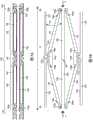
图1A是现有技术支架的横截面端视图。Figure 1A is a cross-sectional end view of a prior art stent.
图1B是图1A所示现有技术支架的结构构件的横截面端视图。Figure IB is a cross-sectional end view of the structural members of the prior art stent shown in Figure IA.
图1C是图1A所示现有技术支架处于膨胀构型的横截面端视图。Figure 1C is a cross-sectional end view of the prior art stent shown in Figure 1A in an expanded configuration.
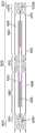
图2A是根据本技术的实施例构造的呈管状构型的可膨胀器械的侧视图。2A is a side view of an expandable device in a tubular configuration constructed in accordance with embodiments of the present technology.
图2B是图2A所示的可膨胀器械的等距视图。Figure 2B is an isometric view of the expandable device shown in Figure 2A.
图2C是图2A和2B所示可膨胀器械的一部分的放大等距视图。Figure 2C is an enlarged isometric view of a portion of the expandable device shown in Figures 2A and 2B.
图2D是图2A-2C所示的可膨胀器械处于平放构型的正视图。Figure 2D is a front view of the expandable device shown in Figures 2A-2C in a flat configuration.
图3A是根据本技术的实施例的图2A-2D所示的可膨胀器械处于中间膨胀构型的侧视图。3A is a side view of the expandable device shown in FIGS. 2A-2D in an intermediate expanded configuration in accordance with an embodiment of the present technology.
图3B是根据本技术的实施例的图2A-2D所示的可膨胀器械处于膨胀构型的侧视图。3B is a side view of the expandable device shown in FIGS. 2A-2D in an expanded configuration, in accordance with an embodiment of the present technology.
图3C是根据本技术构造的脊部的一部分的侧视图,示出为与处于膨胀构型的可膨胀器械隔开。3C is a side view of a portion of a spine constructed in accordance with the present technology, shown spaced from the expandable device in an expanded configuration.
图4A是以收缩构型示出的根据本技术的若干实施例构造的可膨胀器械的放大部分。4A is an enlarged portion of an expandable device constructed in accordance with several embodiments of the present technology, shown in a collapsed configuration.
图4B是以膨胀构型示出的根据本技术的若干实施例构造的可膨胀器械的放大部分。4B is an enlarged portion of an expandable device constructed in accordance with several embodiments of the present technology, shown in an expanded configuration.
图4C是沿线4C-4C截取的如图2A所示的可膨胀器械处于收缩构型的轴向横截面视图。4C is an axial cross-sectional view of the expandable device shown in FIG. 2A in a collapsed configuration, taken along
图4D是沿线4D-4D截取的如图3B所示的可膨胀器械处于膨胀构型的轴向横截面视图。4D is an axial cross-sectional view of the expandable device shown in FIG. 3B in an expanded configuration, taken along
图5A是以收缩构型示出的根据本技术的若干实施例构造的可膨胀器械的放大部分。5A is an enlarged portion of an expandable device constructed in accordance with several embodiments of the present technology, shown in a collapsed configuration.
图5B是以膨胀构型示出的根据本技术的若干实施例构造的可膨胀器械的放大部分。Figure 5B is an enlarged portion of an expandable device constructed in accordance with several embodiments of the present technology, shown in an expanded configuration.
图6A是以膨胀构型示出的根据本技术的若干实施例构造的可膨胀器械的放大部分。6A is an enlarged portion of an expandable device constructed in accordance with several embodiments of the present technology, shown in an expanded configuration.
图6B是根据本技术构造的脊部的一部分的侧视图,示出为与图6A中的可膨胀器械的那部分隔开。6B is a side view of a portion of a spine constructed in accordance with the present technology, shown spaced from that portion of the expandable device in FIG. 6A.
图7A是以膨胀构型示出的根据本技术的若干实施例构造的可膨胀器械的放大部分。7A is an enlarged portion of an expandable device constructed in accordance with several embodiments of the present technology, shown in an expanded configuration.
图7B是根据本技术构造的脊部的一部分的侧视图,其示出为与图7A中的可膨胀器械的一部分隔开。7B is a side view of a portion of a spine constructed in accordance with the present technology, shown spaced from a portion of the expandable device in FIG. 7A.
图8和9是根据本技术的实施例构造的可膨胀器械的轴向横截面视图。8 and 9 are axial cross-sectional views of expandable devices constructed in accordance with embodiments of the present technology.
图10是根据本技术的实施例构造的治疗元件的侧视图。10 is a side view of a therapeutic element constructed in accordance with an embodiment of the present technology.
图11示出了根据本技术的实施例构造的可膨胀器械,示出为定位在腹主动脉瘤内。11 illustrates an expandable device constructed in accordance with embodiments of the present technology, shown positioned within an abdominal aortic aneurysm.
图12A是根据本技术的实施例构造的可膨胀器械的一部分的放大图,示出为植入身体管道内的治疗部位。12A is an enlarged view of a portion of an expandable device constructed in accordance with an embodiment of the present technology, shown implanted at a treatment site within a body duct.
图12B是根据本技术的实施例构造的可膨胀器械的一部分的放大图,示出为植入身体管道内的治疗部位。12B is an enlarged view of a portion of an expandable device constructed in accordance with an embodiment of the present technology, shown implanted at a treatment site within a body duct.
图13图示了根据本技术的实施例构造的可膨胀器械,示出为在输送器械上以收缩构型定位在自体瓣环处。13 illustrates an expandable device constructed in accordance with an embodiment of the present technology, shown positioned at the native valve annulus in a collapsed configuration on a delivery device.
图14A图示了根据本技术的实施例构造的可膨胀器械,示出为在输送器械上以膨胀构型定位在自体瓣环处。14A illustrates an expandable device constructed in accordance with embodiments of the present technology, shown positioned at the native valve annulus in an expanded configuration on a delivery device.
图14B是如图14A中示出为定位在自体瓣环处的可膨胀器械的轴向横截面视图。14B is an axial cross-sectional view of the expandable device as shown in FIG. 14A positioned at the native valve annulus.
图15和16描绘了定位在自体瓣环处的根据本技术的实施例构造的可膨胀器械。15 and 16 depict an expandable device constructed in accordance with an embodiment of the present technology positioned at a native valve annulus.
图17A是根据本技术的实施例构造的输送器械的远侧部分的侧视图。17A is a side view of a distal portion of a delivery instrument constructed in accordance with embodiments of the present technology.
图17B是处于收缩构型的本技术的可膨胀器械的侧视图,示出为定位在图17A的输送器械上。17B is a side view of an expandable device of the present technology in a collapsed configuration, shown positioned on the delivery device of FIG. 17A.
图17C是图17B所示的输送器械和可膨胀器械的侧视图,其中可膨胀器械处于膨胀构型。Figure 17C is a side view of the delivery device and expandable device shown in Figure 17B, with the expandable device in an expanded configuration.
图18A和18B是根据本技术的实施例构造的可膨胀器械的侧视图,以膨胀构型示出并定位在输送器械上。18A and 18B are side views of an expandable device constructed in accordance with embodiments of the present technology, shown in an expanded configuration and positioned on a delivery device.
图19A和19B概念性地描绘了与非环形内腔相比,由本技术的可膨胀器械形成的环形内腔的横截面面积。19A and 19B conceptually depict the cross-sectional area of an annular lumen formed by an expandable device of the present technology as compared to a non-annular lumen.
图20和21A-21C是根据本技术的实施例构造的可膨胀器械的侧视图。20 and 21A-21C are side views of expandable devices constructed in accordance with embodiments of the present technology.
图22示出了根据本技术的若干实施例构造的可膨胀器械。Figure 22 illustrates an expandable device constructed in accordance with several embodiments of the present technology.
图23A和23B分别示出了根据本技术的若干实施例构造的处于收缩构型和膨胀构型的可膨胀器械。23A and 23B illustrate an expandable device in a collapsed and expanded configuration, respectively, constructed in accordance with several embodiments of the present technology.
图24-28描绘了根据本技术的实施例构造的若干可膨胀器械。24-28 depict several expandable devices constructed in accordance with embodiments of the present technology.
图29是示出当本技术的球囊和可膨胀器械处于它们各自的膨胀构型时该球囊和该可膨胀器械之间的相互作用的概念图。29 is a conceptual diagram illustrating the interaction between the balloon and the expandable device of the present technology when the balloon and the expandable device are in their respective expanded configurations.
具体实施方式Detailed ways
本技术涉及可膨胀治疗器械以及相关系统和方法。例如,本技术的一些实施例涉及被配置为定位在身体管道内的支架。该技术的若干实施例的具体细节将在下面参考图2A-29进行描述。The present technology relates to expandable therapeutic devices and related systems and methods. For example, some embodiments of the present technology relate to stents configured to be positioned within body ducts. Specific details of several embodiments of the technology are described below with reference to Figures 2A-29.
一、定义1. Definition
关于本说明书中的术语“远侧”和“近侧”,除非另有说明,否则这些术语可以指代介入器械(例如假体瓣膜器械和/或相关的输送器械)的各个部分关于操作者和/或在脉管系统或心脏中的位置的相对位置。例如,在提及包括本文所述的灌注器械的输送系统时,“近侧”可以指更靠近器械的操作者或血管系统中的切口的位置,而“远侧”可以指代更远离器械的操作者或沿脉管系统更远离切口(例如,导管末端)的位置。With respect to the terms "distal" and "proximal" in this specification, unless otherwise stated, these terms may refer to various parts of an interventional device (such as a prosthetic valve device and/or associated delivery device) relative to the operator and and/or the relative location of the location in the vasculature or heart. For example, when referring to a delivery system including the perfusion devices described herein, "proximal" can refer to a location closer to the operator of the device or an incision in the vasculature, while "distal" can refer to a location further from the device. The operator or a location further down the vasculature from the incision (eg, catheter tip).
如本文所用,“支架”是指被配置为插入解剖血管或通道中以向通道和/或另一医疗器械提供支撑和/或使治疗部位处的生物组织改性的可膨胀医疗器械。As used herein, "stent" refers to an expandable medical device configured to be inserted into an anatomical vessel or channel to provide support to the channel and/or another medical device and/or to modify biological tissue at a treatment site.
如本文所用,“收缩构型”是指可膨胀器械和/或支架的未膨胀构型,可膨胀器械和/或支架被配置为以此构型通过导管输送到治疗部位或从治疗部位取出。如本文所用,“膨胀构型”是指膨胀器械和/或支架的使可膨胀元件部分或完全膨胀的构型。可以仅通过致动(例如,通过球囊的充气)、仅通过自膨胀或两者来实现膨胀构型。在一些实施例中,支架可以支架包括超弹性材料和/或可以热定型为所期望的形状,但超弹性和/或热定型特性在膨胀支架中的作用可以忽略不计。除非本文另有说明,否则“完全膨胀”在用于描述可膨胀器械和/或支架的构型,和/或可膨胀器械和/或支架的横截面尺寸时,是指可膨胀器械和/或支架在治疗或促进治疗所需要的直径下的构型。例如,可膨胀器械和/或支架的完全膨胀构型和/或完全膨胀直径可以与用于膨胀可膨胀器械和/或支架的球囊的完全膨胀直径,或身体管道的测量直径,或略大于身体管道的测量直径的直径相关。如本文所用,“中间膨胀构型”是指可膨胀器械和/或支架的介于收缩构型和完全膨胀构型之间的构型。当可膨胀器械和/或支架被描述为“平放”构型时,应假定可膨胀器械和/或支架处于松弛状态,即,不受任何压力或拉力,也不受任何会导致可膨胀器械和/或支架的脊部彼此远离的力的作用。As used herein, "collapsed configuration" refers to the unexpanded configuration of an expandable device and/or stent configured to be delivered to or removed from a treatment site by a catheter in this configuration. As used herein, "expanded configuration" refers to a configuration of an expansion device and/or stent in which the expandable elements are partially or fully expanded. The expanded configuration may be achieved by actuation alone (eg, by inflation of a balloon), self-expansion alone, or both. In some embodiments, the stent may comprise a superelastic material and/or may be heat set into a desired shape, but the superelastic and/or heat setting properties play a negligible role in expanding the stent. Unless otherwise stated herein, "fully expanded" when used to describe the configuration of an expandable device and/or stent, and/or the cross-sectional dimensions of an expandable device and/or stent means that the expandable device and/or The configuration of the stent at the diameter needed to treat or facilitate treatment. For example, the fully expanded configuration and/or fully expanded diameter of the expandable device and/or stent can be compared to the fully expanded diameter of the balloon used to expand the expandable device and/or stent, or the measured diameter of the body duct, or slightly larger than The measured diameter of the body ducts is diameter dependent. As used herein, an "intermediate expanded configuration" refers to a configuration of an expandable device and/or stent between a collapsed configuration and a fully expanded configuration. When an expandable device and/or stent is described as being in a "lay-flat" configuration, it should be assumed that the expandable device and/or stent is in a relaxed state, i.e., not subject to any compressive or and/or the action of the ridges of the bracket moving away from each other.
如本文所用,术语“纵向”是指沿着延伸穿过可膨胀器械和/或支架处于管状构型时的内腔的轴线的方向,并且术语“周向”可以是指当器械处于管状构型时在正交于纵向轴线的一平面内围绕器械的周围延伸的方向。As used herein, the term "longitudinal" refers to the direction along the axis extending through the lumen of the expandable device and/or stent when it is in the tubular configuration, and the term "circumferential" may refer to the direction along the axis when the device is in the tubular configuration. is the direction extending around the circumference of the instrument in a plane normal to the longitudinal axis.
如本文所用,术语“大体”、“大致”、“约”和类似术语用作近似术语而不是程度术语,旨在说明测量或计算到的值的本领域普通技术人员所公认的固有变化。As used herein, the terms "substantially", "approximately", "about" and similar terms are used as terms of approximation rather than degrees and are intended to account for the inherent variations in measured or calculated values recognized by those of ordinary skill in the art.
如本文所用,“身体管道”和“血液流动通道”是指血液或其他体液有规律地流过的任何解剖结构,例如自体环(在心脏或脉管系统中的任何地方)、心室、血管、输尿管、食道、胆道等。As used herein, "body duct" and "blood flow channel" refer to any anatomical structure through which blood or other bodily fluids flow regularly, such as native annulus (anywhere in the heart or vasculature), ventricles, blood vessels, Ureter, esophagus, bile duct, etc.
二、本技术的可膨胀器械2. The expandable device of this technology
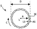
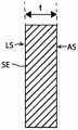
图1A和1C分别示出了常规支架S处于收缩构型和膨胀构型中的轴向横截面视图。包括支架的侧壁由多个相互连接的结构元件SE(例如支柱)形成。如图1B中的结构元件SE之一的放大孤立横截面所示,支架的侧壁具有沿径向维度R在限定侧壁的结构元件的外腔表面AS与限定侧壁的结构元件的内腔表面LS之间测量到的厚度t。由于支架通常由具有恒定厚度的片材或管材切割而成,因此大多数现有支架的厚度沿支架的长度和围绕其周围也是大体恒定的。形成支架壁的结构构件可塑性弯曲(使用球囊膨胀支架)或弹性弯曲(使用自膨胀支架),从而使支架的总直径增大。然而,支架通常被设计成在直径方面膨胀,使得壁厚在膨胀期间保持不变,并且使得限定壁的结构构件在圆柱形表面内保持大体径向对准。由管材切割而成的壁厚为0.010英寸的支架在径向膨胀到更大直径时将仍然具有0.010英寸的壁厚。更大的直径仅由支架的结构构件之间的弧长随着其膨胀而增大来形成。1A and 1C show axial cross-sectional views of a conventional stent S in a collapsed and expanded configuration, respectively. The side walls including the brackets are formed by a plurality of interconnected structural elements SE, such as struts. As shown in the enlarged isolated cross-section of one of the structural elements SE in FIG. 1B , the sidewall of the stent has, along the radial dimension R, a distance between the outer lumen surface AS of the structural element defining the sidewall and the lumen of the structural element defining the sidewall. Thickness t measured between surfaces LS. Since stents are typically cut from a sheet or tube of constant thickness, the thickness of most existing stents is also generally constant along the length of the stent and around its perimeter. The structural members that form the walls of the stent can bend plastically (with balloon-expandable stents) or elastically (with self-expanding stents), thereby increasing the overall diameter of the stent. However, stents are typically designed to expand diametrically such that the wall thickness remains constant during expansion and such that the structural members defining the wall remain generally radially aligned within the cylindrical surface. A stent cut from tubing with a wall thickness of 0.010 inches will still have a wall thickness of 0.010 inches when radially expanded to a larger diameter. Larger diameters result only from the increase in arc length between the structural members of the stent as it expands.
根据本技术的若干方面,本文公开的可膨胀器械包括由管状侧壁形成的支架,其被配置为定位在身体管道(例如血液流动通道)内。支架的径向膨胀会导致侧壁的各个部分屈曲出由侧壁的非屈曲部分限定的圆柱形表面。因此,屈曲部分形成从支架壁径向向内和/或向外延伸出的多个凸块或拱形突起,这为支架提供了优于现有器械的若干优点。例如,屈曲部分可以在支架的主内腔周围形成环形流动区域,当闭塞构件(例如球囊)在主内腔内膨胀并阻塞主内腔时,该环形流动区域提供替代的血液流动通道。屈曲部分可以将主内腔/膨胀球囊和周围组织分开,同时将球囊产生的径向向外的力传递给组织。在这些和其他应用中,屈曲部分可用作摩擦元件,其接合治疗部位处的并置组织(例如血管壁或自体瓣膜小叶),以将可膨胀器械固定在所期望的位置并限制迁移。本技术的这些和其他应用以及伴随的优点将在本文中更详细地讨论。According to several aspects of the present technology, an expandable device disclosed herein includes a stent formed from a tubular sidewall configured to be positioned within a body duct (eg, a blood flow channel). Radial expansion of the stent causes portions of the sidewall to buckle out of the cylindrical surface defined by the non-buckled portions of the sidewall. Thus, the buckled portions form a plurality of bumps or arches extending radially inwardly and/or outwardly from the stent wall, which provides the stent with several advantages over prior devices. For example, the flexed portion may form an annular flow region around the main lumen of the stent that provides an alternate blood flow path when an occlusive member (eg, a balloon) expands within the main lumen and occludes the main lumen. The flexed portion separates the main lumen/inflated balloon from surrounding tissue while transmitting the radially outward force generated by the balloon to the tissue. In these and other applications, the flexed portion can serve as a friction element that engages adjoined tissue at the treatment site (eg, vessel wall or native valve leaflets) to secure the expandable device in a desired position and limit migration. These and other applications of the technology, and attendant advantages, are discussed in greater detail herein.
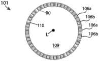
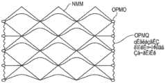
图2A和2D图示了根据本技术的若干实施例构造的可膨胀器械100。图2A和2C示出了处于收缩(即未膨胀)的管状构型的可膨胀器械100,而图2D就像在收缩构型中被纵向切割然后平放时的样子示出了可膨胀器械100。可膨胀器械100被配置为以收缩的管状构型输送到身体管道(例如血液流动通道)内的治疗部位,并在治疗部位径向膨胀以治疗或促进身体管道的治疗。可膨胀器械100可包括支架101,支架101具有第一端部101a、第二端部101b和沿支架101的纵向轴线L(参见图2A)在第一端部101a和第二端部101b之间延伸的长度。支架101可以包括管状侧壁,该管状侧壁由多个纵向延伸的脊部106和在周向相邻的脊部106之间延伸的多个支柱110。如本文详述的那样,脊部106可以包括一个或多个第一部分120,该第一部分120被配置为当可膨胀器械100处于膨胀构型时从支架101的侧壁向外弯曲。2A and 2D illustrate an
根据一些实施例,例如如图2A和2D所示,每个脊部106可以通过一个或多个支柱110连接到相邻的脊部106。例如,每个支柱110可以具有联接到第一脊部106的第一端部和联接到第二脊部106的第二端部。因此,一些或所有支柱110可以在脊部106之间延伸并且可以不直接连接到另一支柱110。在一些实施例中,一些或所有支柱110可以在周向相邻的脊部106之间延伸,使得脊部和支柱围绕支架的周围交替。According to some embodiments, each
支柱110的端部可以通过接头132联接到脊部106。接头132可以对应于支柱110的第一端部和第二端部,也可以从支柱110的第一端部和第二端部延伸出来。接头132可以具有设计成允许支柱110随着器械100径向膨胀而摆动离开相邻的脊部106以及承受由脊部106随着脊部106在膨胀期间彼此远离而施加在支柱110上的张力的宽度、厚度和形状。在一些实施例中,支架101可包括一个或多个未通过支柱110连接到另一脊部106的脊部106和/或一个或多个未连接到支柱110的脊部106。The ends of
根据一些实施例,例如如图2A-2D所示,一些脊部106可以仅跨越支架101长度的一部分,而其他脊部106可以跨越支架101的整个长度。同样,一个、一些或所有脊部106可以具有相同的长度,并且一个、一些或所有脊部106可以具有不同的长度。如图所示,支架101可以包括围绕支架101的周围交替的第一脊部106a和第二脊部106b,其中第一脊部106a短于第二脊部106b。在一些实施例中,第一脊部106a和第二脊部106b具有相同的长度。According to some embodiments, some
在一些实施例中,一个、一些或所有支柱110的第一端联接到第一脊部106a中的一个,而支柱110的第二端可以联接到第二脊部106b中的一个。较长的第二脊部106b可以如图所示那样纵向延伸超过第一脊部106a的一个或两个纵向端,或者第二脊部106b的纵向端可以与第一脊部106a的纵向端对准。在一些实施例中,任何第一脊部106a都不与另一第一脊部106a周向相邻并且任何第二脊部106b都不与另一第二脊部106b周向相邻。在一些实施例中,两个或更多个第一脊部106a可以周向相邻和/或两个或更多个第二脊部106b可以周向相邻。In some embodiments, the first ends of one, some or all of the
至少当支架以平放视图表示时,例如如图2D所示,一个、一些或所有脊部106可以是大致线性的并且大致平行于:(a)支架101的纵向轴线L,(b)一个、一些或所有支柱110,和/或(c)一个、一些或所有其他脊部106。在这些和其他实施例中,当支架101处于收缩构型时,一个、一些或所有脊部106可以是大致线性的并且大致平行于:(a)纵向轴线L,(b)一个、一些或所有支柱110,和/或(c)一个、一些或所有其他脊部106。At least when the stent is shown in a lay-flat view, such as shown in FIG. Some or all
一些或所有支柱110可以是大致线性的,如图2A-2D所示。至少当支架以平放视图表示时,例如如图2D所示,支柱110可以是大致线性的并且大致平行于:(a)纵向轴线L,(b)一个、一些或所有脊部106,和/或(c)同一支柱区域102和/或一些或所有其他支柱区域内的其他支柱110。在这些和其他实施例中,当支架101处于收缩构型时,支柱110可以是大致线性的并且大致平行于:(a)纵向轴线L,(b)一个、一些或所有脊部106,和/或(c)同一支柱区域102和/或部分或全部其他支柱区域内的其他支柱110。根据一些实施例,当支架处于膨胀构型时,脊部110可以是大致线性的并且相对于纵向轴线L成一定角度和/或相对于一个、一些或所有脊部106成一定角度。在一些实施例中,一个或多个支柱110的全部或一部分当支架101处于收缩构型和/或当支架101处于膨胀构型时可以被弯曲。Some or all of the
如图2D所示,支架101可以包括多个支柱区域102,每个支柱区域102包括支柱110的周向箍带,相邻的支柱110在该周向箍带中被脊部106的共同延伸长度分开。每个支柱区域102可以纵向设置在区域102内的支柱110的第一端部和第二端部之间(并且类似地,设置在区域102内的支柱110的端部处的接头132之间)。至少当支架101处于收缩构型时,给定支柱区域102内的支柱110的第一端部可以彼此纵向对准,而给定支柱区域102内的支柱110的第二端部可以彼此纵向对准。As shown in FIG. 2D ,
根据一些实施例,每个支柱区域102的第一纵向侧可以通过由面向支架101的第二端部101b的第一成对133a接头132组成的周向箍带限定(即附接在第一成对133a接头132的支柱110形成沿第二端部101b的方向开口的V形),而每个支柱区域102的第二纵向侧可以通过由面向支架101的第一端部101a的第二成对133b接头132组成的周向箍带限定(即,附接到第二成对133b接头132的支柱110形成沿第一端部101a的方向开口的V形)。第一成对133a接头可以沿着第一脊部106a设置,而第二成对133b接头可以沿着第二脊部106b设置。According to some embodiments, the first longitudinal side of each
支柱区域102可以沿支架101的长度彼此纵向相邻,使得第一支柱区域102的第一成对133a接头132的箍带可以纵向邻近纵向相邻的第二支柱区域102的第二成对133b接头132的箍带。脊部106可以纵向延伸穿过两个或更多个支柱区域102,因此至少一些第一对133a经由相应脊部106沿其设置对133a、133b的第二部分122(如下所述)联接到第二对133b。纵向相邻且径向对准的第一成对133a接头和第二成对133b接头都可包括节点134。The
根据一些实施例,例如如图2D所示,一个、一些或所有脊部106可以包括沿相应的脊部106的长度交替的第一部分120和第二部分122。第一部分120和第二部分122中只有少数被标记在图2D中,以便于观察支架的结构。第一部分120的第一端部120a和第二端部120b(参见图3C)可以联接到第二部分122中的一个并与其连续。第一部分120可以跨越一个、两个或更多的支柱区域102,并且所述第二部分122可以在纵向相邻的支柱区域102之间和纵向相邻的第一部分120之间延伸。在一些实施例中,例如如图2D所示,第一脊部106a的第一部分120a相对于第二脊部106b的第一部分120b纵向交错,使得第一脊部106a的第一部分120a和第二脊部106b的第一部分120b仅沿着它们各自长度的一部分共同延伸。According to some embodiments, one, some or all of the
如图2D最佳所示,支架101可以包括多个脊部区域121,每个脊部区域121包括周向相邻的第一部分120的周向箍带和联接到第一部分120中的每个的四个支柱110。每个脊部区域121可纵向设置在相应第一部分120的任一侧上的第二端部122之间。在支架101包括第一脊部106a和第二脊部106b的那些实施例中,支架101可包括沿着第一脊部106a的第一脊部区域121a和沿着第二脊部106b的第二脊部区域106b。第一脊部区域121a内的第一部分120可大体周向对准,并且第二脊部区域121b内的第一部分120可大体周向对准对准,而第一脊部区域121a中的第一部分120和第二脊部区域121b中的第一部分120可以沿周向偏移。As best shown in FIG. 2D , the
支架101可以包括不同数量的第一脊部区域121a和第二脊部区域121b。例如,在图2D所示的实施例中,支架101包括三个第一脊部区域121a和两个第二脊部区域121b。在其他实施例中,支架101可以包括更多或更少的第一脊部区域121a和/或更多或更少的第二脊部区域121b。在图2D所示的实施例中,每个脊部区域121包括12个第一部分120和48个支柱110,支架101约25mm长,总共有60个第一部分120和总共144个支柱110。在其他实施例中,支架101可以更长或更短和/或包括在每个脊部区域121中的多于或少于12个的第一部分120(例如,每个脊部区域121中包括1、2、3、4、5、6、7、8、9、10、11、13、14、15、16、17、18、19、20、22、23、24等个第一部分120)、在给定脊部区域121和/或第一部分120内的一个或多个屈曲部分150(参见图3A和3B)、在每个脊部区域121中的多于或少于48个的支柱110(例如,每个脊部区域121中包括0、2、4、6、8、10、12、14、16、18、20、22、24,26、28、30、32、36、40、44、52、56、60、64、68、72、76、80等个支柱110)、多于或少于总共60个的第一部分120和/或多于或少于总共144个的支柱110。第一和第二脊部区域121可以具有相同或不同数量的第一部分120和/或支柱110。在一个、一些或所有脊部区域121内或者在没有脊部区域121的情况下,支柱110与第一部分120的比率可以是2比1、3比1、4比1、5比1、6比1、7比1、8比1等。The
第一脊部区域121a和第二脊部区域121b可以沿着支架101的纵向轴线重叠(如图2D所示),或者第一脊部区域121a和第二脊部区域121b可以彼此纵向相邻或间隔开。在一些实施例中,支架101包括一些重叠脊部区域121和一些相邻或间隔开的脊部区域121。脊部区域121可以重叠例如支柱区域102的长度,使得纵向重叠脊部区域121共享支柱区域102。The first ridge region 121a and the second ridge region 121b may overlap along the longitudinal axis of the stent 101 (as shown in FIG. 2D ), or the first ridge region 121a and the second ridge region 121b may be longitudinally adjacent to each other or Spaced out. In some embodiments, the
图3A和3B分别是处于中间膨胀构型和完全膨胀构型的支架101的侧视图,而图3C是当支架101处于完全膨胀构型时脊部106的第一部分120之一的侧视图。根据一些实施例,例如如图3A-3C所示,支架101从收缩构型转变为膨胀构型会导致第一部分120从由第二部分122限定的大致圆柱形表面CS向外弯曲,第一部分120形成径向延伸远离侧壁其余部分的多个屈曲部分150。例如,屈曲部分150可以沿着一个或多个脊部106设置并且可以间隔开约支架101的长度和/或周长。3A and 3B are side views of
在一些实施例中,例如如图3A和3C所示,屈曲部分150包括相应脊部106的拱形区域。屈曲部分150可以在第一端部120a和第二端部120b之间具有峰部区域124,其中峰部区域124包括屈曲部分150的径向距离第二部分122最远的位置或区域。如本文所讨论过的那样,在(a)由多个第二部分122限定的圆柱形表面CS和(b)屈曲部分150的峰部区域124之间测量到的径向距离R限定环形内腔由屈曲部分150形成的厚度。In some embodiments, such as shown in FIGS. 3A and 3C , the flexed
如图2D所示,每个屈曲部分150可以跨越两个支柱区域102。在一些实施例中,一个、一些或所有屈曲部分150跨越多于两个支柱区域102(例如,三个支柱区域、四个支柱区域等)。第一脊部106a与第二脊部106b相比,可以具有更少的屈曲部分150,反之亦然。在一些实施例中,第一脊部106a和第二脊部106b具有相同数量的屈曲部分150。一个、一些、没有或全部给定脊部106可以具有单个屈曲部分150。屈曲部分150沿给定脊部106的长度可以相同也可以不同,并且第二部分122沿给定脊部106的长度可以相同也可以不同。附加地或替代地,一些或所有脊部106的屈曲部分150可以具有不同的长度。As shown in FIG. 2D , each flexed
根据一些实施例,支柱110在支架101径向膨胀期间的移动可轴向压缩脊部106的各个部分,从而导致第一部分120远离圆柱形表面CS弯曲并形成屈曲部分150。例如,图4A和4C描绘了处于收缩构型的支架101的一部分,而图4B和4D示出了处于膨胀构型的支架101的一部分。图4A和4C中所示的部分包括一个脊部106的第一部分120和处于该第一部分120的任一纵向端处的第二部分122,以及经由第一成对133a接头和第二成对133b接头处的接头132联接到脊部106的第一部分120的第一支柱140、第二支柱142、第三支柱144和第四支柱146。至少在收缩构型中,第一部分120的第一端部120a和第二端部120b可以沿着支架101的纵向轴线分开第一长度L1,并且周向相邻的脊部148、149可以与脊部106的纵向轴线分开一弧长AL。同样在收缩构型中,如图4C最佳所示,支柱110(包括支柱140、142、144、146)和脊部106与支架101的中心纵向轴线L的径向距离R0可以大致相同并且一起限定主内腔109。Movement of
在如图4A和4B所示的支架101的放大部分中,第一支柱140的第一端部140a连接到脊部106的第一部分120的第一端部120a,而第一支柱140的第二端部140b连接到第一周向相邻脊部148的第二部分122(仅示出一部分)或侧壁的其他结构构件。第二支柱142的第一端部142a连接到第一周向相邻脊部148的第二部分122(仅示出一部分)或侧壁的其他结构构件,而第二支柱142的第二端部142b连接到脊部106的第一部分120的第二端部120b。第三支柱144的第一端部144a连接到脊部106的第一部分120的第一端部120a,而第三支柱144的第二端部144b连接到脊部106的第二周向相邻脊部149的第二部分122(仅示出一部分)或侧壁的其他结构构件。第四支柱146的第一端部146a连接到第二周向相邻脊部149的第二部分122(仅示出一部分)或侧壁的其他结构构件,而第四支柱146的第二端部146b连接到脊部106的第一部分120的第二端部120b。In the enlarged portion of the
支架101的径向膨胀增大了(a)脊部106和(b)支架101的纵向轴线L之间的径向距离,这又增大了周向相邻脊部106之间的弧长AL。随着脊部106之间的周向距离增大,支柱110与它们所附接的脊部106成一定角度。例如如图4B所示,随着脊部106和周向相邻脊部148、149之间的弧长AL增大,(a)第一支柱140的第二端部140b和第二支柱142的第一端部142a一起沿第一周围方向远离脊部106移动(例如,借助于节点134a),而(b)第三支柱144的第二端部144b和第四支柱146的第一端部146a沿与第一周围方向相反的第二周围方向远离脊部106移动(例如,借助于节点134b)。结果,附接至脊部106的支柱140、142、144、146的端部140a和142b、144a和146b被纵向拉向彼此,并且这样做时连同它们一起驱动脊部106的第一部分120的附接端部120a、120b(图4B中用箭头A表示)。该移动纵向压缩脊部106,使得脊部106的第一端部120a和第二端部120b之间的纵向距离从收缩构型中的第一长度L1减小到较短的第二长度L2。至适应这种轴向压缩,第一部分120从第二部分122向外弯曲以形成屈曲部分150。因此,如图4D最佳所示,当支架101处于膨胀构型时,(a)支柱110和脊部106的第二部分122距离中心纵向轴线L第一径向距离R1,并且(b)脊部106的第一部分120距离中心纵向轴线L第二更大径向距离R2。Radial expansion of the
根据一些实施例,例如如图4D所示,当支架101处于膨胀构型时,支架101限定了两个独立的直径,其可用于限定两个独立的内腔。支架101可以具有由径向对准的支柱110和脊部106的第二部分122限定的第一主内腔109,以及介于(a)脊部106的第一部分120和(b)支柱110和脊部106的第二部分122之间的第二环形内腔108。该环形内腔108可具有在(a)脊部106的第一部分120和(b)支柱110和脊部106的第二部分122之间测量到的厚度t。本技术的可膨胀器械100和/或支架101的同轴内腔对于需要在血液流动通道内将被充气的球囊以临时阻塞血液流动的应用特别有利。例如,可膨胀器械100和/或支架101可在主内腔109内接纳一球囊,并且该球囊可在主内腔109内膨胀,这也膨胀支架101。由屈曲部分150形成的环形内腔108在球囊在主内腔109中膨胀的同时提供通过身体管道的血液流动通道。本技术的该特征的其他细节和具体应用在本文别处讨论。According to some embodiments, when the
根据一些实施例,例如如图4D所示,屈曲部分150可以以约90度的角度α从大致圆柱形表面CS径向远离(向外或向内)而延伸。在一些实施例中,一个、一些或所有屈曲部分150可以以非90度的角度径向远离大致圆柱形表面CS延伸(未示出)。然而,在一些情况下,确保一个、一些或所有屈曲部分150以约90度的角度径向远离大致圆柱形表面CS(向外或向内)延伸可能是有益的。在这样的实施例中,构造脊部106和/或支柱110以改善屈曲部分150的方向稳定性和/或角度可预测性可能是有益的。例如如图5A和5B所示,在一些实施例中,脊部106的一个、一些或所有第一部分120具有直接连接到支柱110而不是连接到第二部分122或末端对133的端部。第一部分120可以在其一个末端或两个末端处分支成两条腿107,并且每条腿107可以连接到支柱110之一。结果,随着支柱110周向膨胀并且脊部106开始屈曲,腿107为脊部106建立更宽的横向支撑并且引导屈曲部分150相对于支架101的其余部分成大致径向向内或向外的定向。附加地或替代地,支架101的第一部分120可以预先形成(例如,通过热处理)以促进形成所期望的定向的屈曲部分150。According to some embodiments, flexed
在一些实施例中,脊部106(沿着第一部分120和/或第二部分122)的厚度和/或宽度可以变化以实现期望的屈曲轮廓,和/或脊部106的全部或部分可以在特定位置处预先形成弯曲和/或预先形成特定形状。一个、一些或所有第一部分120可以沿它们的长度具有大致恒定的厚度和/或宽度(例如如图4A和4B所示),这产生单个峰部124和更正弦的屈曲轮廓。如图6A和图6B所示,在一些实施例中,一个、一些或所有第一部分120可以在期望的峰部位置处具有凹陷部125,并且可选地靠近第一端部120a和第二端部120b。凹陷部125可以由脊部106的具有减小了宽度的长度形成(如图所示),和/或可以包括脊部106的具有减小了厚度的长度。由于凹陷部125的缘故,所得到的屈曲部分150具有更紧密的弯曲并且呈现出更三角形的形状,如图6B所示。该峰部可以沿所述脊部的长度相对居中(如图6B所示),它也可以更靠近脊部的一端,给出不对称屈曲轮廓。附加地或替代地,凹陷部125可以被配置为使得屈曲部分150具有相对平坦的峰部124(与图6B中所示的“更尖”的峰部124相比),从而提供更多的表面区域,用于接合并置组织、支架、球囊或其他器械。更平坦的峰部也可以提供较小的创伤表面,用于接合不同的并置材料。In some embodiments, the thickness and/or width of spine 106 (along
在一些实施例中,例如如图7A和7B所示,一个、一些或所有第一部分120可具有多个凹陷部125,使得第一部分120在可膨胀器械100和/或支架101径向膨胀时形成两个或更多个屈曲部分150(或两个或更多个峰部124)。在这样的实施例中,与第二部分122和/或支柱110相比,屈曲部分150之间的谷部可以径向远离中心纵向轴线。第一部分120沿着特定的脊部106:(a)可以对每个第一部分120形成相同或不同数量的屈曲部分150,(b)可以形成具有相同或不同形状或轮廓的屈曲部分150,和/或(c)可以具有相同或不同的长度。特定脊部区域121内的第一部分120:(a)可以对每个第一部分120形成相同或不同数量的屈曲部分150,(b)可以形成具有相同或不同形状或轮廓的屈曲部分150,和/或(c)可以具有相同或不同长度。In some embodiments, such as shown in FIGS. 7A and 7B , one, some or all of the
在一些情况下,脊部106可以随着支架101径向膨胀而倾斜以沿不同方向屈曲,其中一些径向向外屈曲而一些径向向内屈曲。在某些情况下,可以优选促进所有屈曲部分150沿同一方向延伸。为了促进这一功能,支架101可以预先形成(例如,通过热处理),使得脊部106的所有第一部分120沿同一期望径向方向(即,径向向内或向外)屈曲。例如,部分或整个支架101可以预成型为松弛且不受约束的直径,该直径约是整个输送导管的直径,使得即使在可膨胀器械已经被输送并且支架101处于其松弛尺寸之后,松弛的器械也可以通过护套或引导导管移除。在TAVR的情况下,直径可以取14-21Fr或4.7mm-7mm。附加地或替代地,如图8所示,在一些应用中,可以优选使所有屈曲部分150径向向内屈曲。如图9所示,在一些实施例中,脊部106可以径向向内和径向向外屈曲,从而产生与所有屈曲部分150沿同一径向方向延伸的支架相比两倍的厚度t。In some cases,
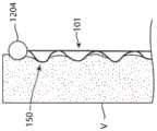
如前所述,可膨胀器械100和/或支架101可通过膨胀放置在支架101的主内腔109中的球囊而膨胀。位于球囊200上方的可膨胀器械100的示例示出在如图10中。As previously described, the
根据一些实施例,本技术的可膨胀器械100和/或支架101是自膨胀的。例如,支架101的全部或一部分可以包括具有超弹性特性的材料,例如镍钛诺。在一些或所有这样的实施例中,支架在松弛状态下可形成小直径管。可膨胀器械100和/或支架101也可以被热处理和/或预成型,使得在其松弛且不受约束的状态下,它的直径小于器械的完全膨胀直径。在这样的实施例中,支架101可以收缩到其较小的松弛直径。附加地或替代地,本技术的可膨胀器械100和/或支架101可包括塑性变形支架,例如由不锈钢或钴铬合金制成的支架。According to some embodiments, the
在本文公开的任何实施例中,屈曲脊部可以相对于支架的纵向轴线成一定角度。In any of the embodiments disclosed herein, the flexion ridge may be angled relative to the longitudinal axis of the stent.
三、用于内移植的可膨胀器械的选定实施例3. Selected embodiments of expandable devices for endografting
本技术的可膨胀器械100在用于内移植时具有明显优势。在主动脉内移植的情况下尤其如此。例如,屈曲部分150可以形成摩擦元件,其接合自体主动脉壁以至少在短期内限制支架迁移。The
除了屈曲部分与主动脉壁的剧烈摩擦接合以在短期内限制迁移之外,从长远来看,屈曲部分150可能愈合到主动脉壁中,从而使长期迁移更加困难。随着血管器械(例如支架)愈合到血管中,通常会有愈合反应,其导致在异物周围形成平滑肌细胞。对于屈曲部分150,这种愈合响应可以导致与主动脉或血管壁的机械接合比现有技术的支架的情况更强。In addition to the severe frictional engagement of the buckling portion with the aortic wall to limit migration in the short term, the buckling
如果本技术的可膨胀器械100和/或支架101用作主动脉内移植物的一部分,并且屈曲部分侵略性地愈合到主动脉壁中,则它们也可以防止在内移植物放置后的数月和数年内自体主动脉进一步扩张。在许多主动脉内移植手术中,已经注意到主动脉随着时间推移的继续扩张,导致主动脉壁与内移植物分开,导致泄漏、对自体动脉瘤主动脉壁的新压力和潜在的破裂。屈曲部分150可以永久且侵略性地愈合到主动脉壁,从而防止长期主动脉壁扩张和与内移植壁分开。If the
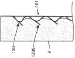
在一些主动脉内移植器械中,可以优选在支架的特定区域处(例如在期望永久向内生长和愈合到血管壁的支架末端处)形成屈曲部分150。图11示出了根据本技术构造的主动脉内移植器械,其示出为定位在横跨腹主动脉瘤(“AAA”)的主动脉中。如图所示,器械1200可以包括具有端部1202的支架,该端部1202包括屈曲部分150以促进向内生长。在一些实施例中,例如如图12A所示,支架可在可膨胀器械1200的端部处包括管状移植材料的外翻边1204(除了或代替屈曲端部1202)。外翻边1204可促进内移植物和主动脉壁(或可膨胀器械放置在其中的任何身体导管的壁)之间的直接密封并限制到由屈曲部分150临时形成的环形空间中的任何急性泄漏。在一些实施例中,如图12B所示,本技术的支架可以包括一个或多个固定构件1206。例如,固定构件1206可以沿着一个、一些或所有第一部分120定位,使得支架101的径向膨胀和第一部分120的相应屈曲致动固定构件1206以远离屈曲部分150突出并伸入相邻组织。固定构件1206可以是创伤性的或无创伤性的。代替第一部分120或除了第一部分120之外,本技术的可膨胀器械和/或支架还可以在支架的其他部分处包括固定构件1206。例如,本技术的可膨胀器械和/或支架可以在脊部106的一个、一些或所有第二部分122处和/或在一个、一些或所有支柱110处包括固定构件。In some endo-aortic graft devices, it may be preferable to form flexed
应当理解,关于内移植讨论过的任何前述概念也可以应用于本文讨论过的任何实施例,而不管临床应用如何。例如,端部1202、外翻边1204、固定构件1206等可以是结合到本文关于瓣膜成形术、支架瓣膜输送等讨论过的任何可膨胀器械和/或支架中。It should be understood that any of the foregoing concepts discussed with respect to endografting can also be applied to any of the embodiments discussed herein, regardless of the clinical application. For example, the
在本文详述的任何实施例中,包括用于内移植的实施例,支架可以是自膨胀的。因为随着动脉瘤主动脉退化,器械和血管壁之间的密封对于球囊可膨胀实施例可能不太有效,所以自膨胀形式可能特别有益的。本文公开的一排内固定器可被配置为重新定位,因此可以在短期内重新定位,从而允许更精确地放置近侧颈部,然后随着支架的屈曲部分长期向主动脉壁生长而更安全地密封且迁移更少。In any of the embodiments detailed herein, including embodiments for endografting, the stent can be self-expanding. Since the seal between the device and vessel wall may be less effective with balloon-expandable embodiments as the aneurysmal aorta degenerates, the self-expanding form may be particularly beneficial. The array of internal fixators disclosed herein can be configured to be repositionable and therefore repositionable in the short term, allowing for more precise placement of the proximal neck, and then more securely as the flexed portion of the stent grows into the aortic wall in the long term Earth seals and migrates less.
四、用于瓣膜成形术的可膨胀器械的选定实施例IV. Selected Embodiments of Expandable Devices for Valvuloplasty
本技术的可膨胀器械可构造用于瓣膜成形手术,尤其是那些采用球囊膨胀支架的手术。例如,图13描绘了本技术的可膨胀器械,包括支架101,其以收缩构型定位在自体瓣环。图14A示出了处于膨胀构型并且在自体瓣环处定位膨胀球囊200上方的支架101。图14B是沿图14A中线14B-14B截取的横截面视图。为了改善瓣膜成形术的有效性,本技术的支架101可以放置在管状瓣膜成形术球囊的外侧。在其压缩直径下(即,在收缩构型中),支架101的壁厚可以与从其切割出支架101的管材一样薄。因此,支架101不会对整个器械的压缩输送轮廓增大太多。随着球囊膨胀,支架101的直径可以膨胀,但屈曲部分150会形成额外的厚度,从而它在其内径和外径之间形成血液可以流过的开放环形空间108。The expandable devices of the present technology can be configured for use in valvuloplasty procedures, particularly those employing balloon-expandable stents. For example, FIG. 13 depicts an expandable device of the present technology including a
本技术的可膨胀器械100和/或支架101可以对瓣膜成形术具有许多积极影响。由支架101的环形内腔启用的灌注能力允许瓣膜成形术球囊200在一延长的时间段内保持充气,从而能够潜在地更好更完全地扩张狭窄的瓣膜。这可能会产生更完全且永久性的瓣膜成形术效果。The
随着屈曲部分150接触自体瓣膜,它们可以将更集中的力施加到钙化瓣膜和瓣环上的多个焦点。这种更高的局部化力可以使瓣膜成形术球囊更有效地分解钙化和恢复更完全的瓣叶移动。更高的局部化力可以进一步增大瓣膜的有效孔面积。在某些情况下,对球囊200进行多次充气/放气可能是有利的。可膨胀器械100和/或支架101可以在充气之间旋转或推进或抽出,使得屈曲支柱150压靠在自体瓣膜和瓣环的多个不同的焦点区域上,从而实现更完全和更有效的瓣膜成形术。As flexed
根据一些实施例,例如如图15所示,可膨胀器械可包括支架(例如本文所述的支架101)和薄柔性材料1502(例如膨胀聚四氟乙烯(EPTFE或“Gore-Tex”)、聚氨酯、聚乙烯或定位在支架101上方的其他材料)的套管。材料1502的套管可以被配置为充当单向阀以在球囊充气期间维持主动脉压力并防止反流。支架101的屈曲部分150可以径向向外延伸(如图所示)并压靠在自体瓣环和/或其他相邻组织上。在一些实施例中,屈曲部分150径向向内延伸。在一些实施例中,一些屈曲部分150径向向内延伸,而一些屈曲部分径向向外延伸。关于单向阀的附加细节在本文别处提供。According to some embodiments, for example as shown in FIG. 15 , an expandable device may comprise a stent such as
根据一些实施例,例如如图16所示,可膨胀器械可被配置为过滤或捕获在瓣膜成形手术期间产生的任何栓塞碎片。可膨胀器械可以包括例如支架(例如本文所述的支架101)和联接到支架101的端部的过滤器1602。支架101的屈曲部分150可以径向向外延伸(如图所示)并且压靠在自体瓣环和/或其他相邻组织上。在一些实施例中,屈曲部分150径向向内延伸。在一些实施例中,一些屈曲部分150径向向内延伸,而一些屈曲部分150径向向外延伸。According to some embodiments, for example as shown in FIG. 16, the expandable device may be configured to filter or capture any embolic debris generated during the valvuloplasty procedure. An expandable device may include, for example, a stent (such as
应当理解,关于瓣膜成形术讨论过的任何前述概念也可以应用于本文讨论过的任何实施例,而不管临床应用如何。例如,套管1502、过滤器1602等可以结合到本文关于内移植、支架瓣膜输送等所讨论过的任何可膨胀器械和/或支架。It should be understood that any of the foregoing concepts discussed with respect to valvuloplasty may also be applied to any of the embodiments discussed herein, regardless of the clinical application. For example,
五、用于支架瓣膜输送的可膨胀器械的选定实施例V. Selected Embodiments of Expandable Devices for Stent-Valve Delivery
经导管主动脉瓣置换术(TAVR)是目前最常见的主动脉瓣置换术方法。它比手术瓣膜置换术更受欢迎,因为它避免了手术创伤、恢复时间和其他与手术相关的并发症。最流行的TAVR系统类型是一种球囊可膨胀TAVR器械,例如Edwards Laboratories的SAPIEN系列瓣膜(为了便于参考,SAPIEN 1、2和3型在本文中统称为“SAPIEN”)。SAPIEN TAVR器械是一种由安装在一个钴铬合金支架的牛心包组织制成的瓣膜。该SAPIEN支架瓣膜被压缩到输送导管末端处的已放气圆柱形球囊上。然后将支架瓣膜推进到患者的股动脉中并沿主动脉向上到达主动脉瓣。然后球囊会快速充气以抵靠在自体主动脉瓣上膨胀支架。在快速确认支架完全膨胀后,球囊会很快放气。Transcatheter aortic valve replacement (TAVR) is currently the most common procedure for aortic valve replacement. It is preferred over surgical valve replacement because it avoids surgical trauma, recovery time, and other complications associated with the procedure. The most popular type of TAVR system is a balloon-expandable TAVR device such as the Edwards Laboratories SAPIEN series of valves (SAPIEN Types 1, 2 and 3 are collectively referred to herein as "SAPIEN" for ease of reference). The SAPIEN TAVR device is a valve made of bovine pericardium tissue mounted in a cobalt-chromium alloy stent. The SAPIEN stent-valve is compressed onto a deflated cylindrical balloon at the end of the delivery catheter. The stent-valve is then advanced into the patient's femoral artery and up the aorta to the aortic valve. The balloon is then rapidly inflated to expand the stent against the native aortic valve. After a quick confirmation that the stent is fully inflated, the balloon deflates quickly.
球囊的放气需要非常快速地发生,因为当球囊充气时,球囊会阻塞主动脉瓣并且没有流动通过主动脉瓣。这会导致全身动脉压暂时降低,这本身并不是明显风险。但左心室无法排出任何血液的事实意味着,随着每次心跳,越来越多的血液被泵入左心室,并且它越来越膨胀。这可能导致危险和创伤性的过度膨胀,甚至导致左心室破裂。为了防止这种情况发生,在TAVR部署之前,将起搏导管引入并拧入心脏壁,并且就在TAVR球囊充气之前,心脏以约每分钟200次的高速率起搏。在200次/分钟的速度下,心室在心跳之间来不及扩张和充盈,从而防止了心室发生危险的过度膨胀。The deflation of the balloon needs to happen very quickly because when the balloon is inflated, the balloon blocks the aortic valve and there is no flow through the aortic valve. This causes a temporary decrease in systemic arterial pressure, which is not an obvious risk in itself. But the fact that the left ventricle cannot expel any blood means that, with each heartbeat, more and more blood is pumped into the left ventricle, and it expands more and more. This can lead to dangerous and traumatic overdilation and even rupture of the left ventricle. To prevent this from happening, before TAVR is deployed, a pacing catheter is introduced and screwed into the heart wall, and just before the TAVR balloon is inflated, the heart is paced at a high rate of about 200 beats per minute. At 200 beats per minute, the ventricles have too little time to expand and fill between heartbeats, preventing dangerous overinflation of the ventricles.
然而,长时间以这种快速的速度使心脏起搏很危险。TAVR期间快速起搏时间延长与心房颤动、急性肾损伤、操作性低血压延长和总体死亡率升高有关。因此,医生努力使球囊尽可能快地充气和放气,并且整个快速起搏和支架瓣膜部署的程序通常在不到半分钟的时间内完成。起搏导管的添加也逐渐增加了整体TAVR植入的时间、费用和复杂性。However, pacing the heart at such a rapid rate for prolonged periods of time is dangerous. Prolonged rapid pacing during TAVR is associated with atrial fibrillation, acute kidney injury, prolonged procedural hypotension, and increased overall mortality. Physicians therefore strive to inflate and deflate the balloon as quickly as possible, and the entire procedure of rapid pacing and stent-valve deployment is typically completed in less than half a minute. The addition of a pacing catheter also gradually increases the time, cost, and complexity of the overall TAVR implantation.
由于前述原因,TAVR部署过程是相对高压力和高风险的过程。有限的可用时间增加了瓣膜定位不当(例如主动脉根部太低或瓣环上方太高)的风险,其中瓣膜装置的一部分可能会阻塞冠状动脉。球囊可膨胀部署过程的仓促性质也增加了支架瓣膜部署不完全的风险。这可能导致支架与主动脉环不完全贴合进而产生瓣周渗漏,或导致该环的不完全扩张进而导致非圆形的最终支架几何形状。支架不完全扩张会明显增加瓣叶磨损增加和早期瓣膜失效的发生率。For the foregoing reasons, the TAVR deployment process is a relatively high-stress and high-risk process. The limited time available increases the risk of valve mispositioning (eg, too low in the aortic root or too high above the annulus), where part of the valve device could occlude the coronary artery. The hasty nature of the balloon-expandable deployment process also increases the risk of incomplete stent-valve deployment. This can result in incomplete fit of the stent to the aortic annulus, resulting in paravalvular leak, or incomplete expansion of the annulus, resulting in a non-circular final stent geometry. Incomplete expansion of the stent significantly increases the incidence of increased leaflet wear and early valve failure.
由于所有上述原因,优选具有在支架膨胀过程中允许流动通过主动脉瓣的球囊,以允许医生在完全正确的位置上逐渐和完全部署支架,而没有任何时间压力。For all of the above reasons it is preferable to have a balloon that allows flow through the aortic valve during stent expansion to allow the physician to gradually and fully deploy the stent in exactly the correct position without any time stress.
图17A示出了根据本技术的若干实施例构造的TAVR输送总成1700的远侧部分。如图17A所示,输送总成可以包括球囊200(在图17A中以收缩状态示出)和位于球囊200的每一端下方的成型保持元件以在输送期间将支架瓣膜(未示出)保持在适当位置。图17B示出了相同的TAVR输送总成1700,其中本技术的支架(例如支架101)叠加在保持支架瓣膜的球囊部分上。图17C示出了一总成1700,其中被充气的球囊200使支架101和支架瓣膜1702(以横截面示出)膨胀,血液流过屈曲支架101。Figure 17A illustrates a distal portion of a
图18A示出了与图17C相同的总成,但具有由很薄的柔性材料(例如EPTFE)制成的管状套管1802。管状套管1802可以形成单向阀以防止在舒张期间血液通过器械向后回流。管状套管1802可以结合支架的大部分屈曲部分150以在其被充气时保持在适当位置上,同时在支架收缩时仍允许其收缩和折叠。该套管1802近端可以以多种方式压合或缝合以促进套管1802在舒张期闭合。一种这样的方式示出在图18B中。套管1802也可以在近侧拴在输送导管的轴上,也可以如图18B所示那样将其保持在适当位置上并防止其由于血压而向远侧收缩。Figure 18A shows the same assembly as Figure 17C, but with a
在许多情况下,可能需要相对适中程度的屈曲来提供足够的血流。为了演示,图19A和19B对照圆形内腔111(图19B中所示),概念性地描绘了由本技术的可膨胀器械创建的环形内腔108的横截面区域(图19A中所示)。在本例中,屈曲脊部120的外径为24mm(或R=12mm),而内腔109的直径为21mm(或R=10.5mm)。在这种情况下,环形内腔108的厚度t为1.5mm,而环形内腔108的周长约为70mm。因此,环形内腔108的横截面面积约为105平方毫米,约等于圆柱形内腔在直径为11.6mm时的面积111(如图19B所示)。这提供了足够多的横截面面积,以允许心脏在稳态基础上将血液泵入主动脉,而不会产生过大的压力梯度。应当理解,上述尺寸作为解释提供并且不限制本技术的可膨胀器械和/或支架本身。In many cases, a relatively moderate degree of flexion may be required to provide adequate blood flow. For demonstration, FIGS. 19A and 19B conceptually depict the cross-sectional area of annular lumen 108 (shown in FIG. 19A ) created by an expandable device of the present technology in contrast to circular lumen 111 (shown in FIG. 19B ). In this example, the outer diameter of the flexing
根据一些实施例,可膨胀器械100和/或支架101可具有约25mm的长度,设计成安装在放置瓣膜的球囊上。在给定的脊部区域121内,支架101可以具有一系列12个第一部分120以及围绕其周围的24对支柱110,并且可以在其长度上具有5个脊部区域121。每个脊部区域121可以包括12个第一部分120,其在膨胀构型中形成12个屈曲部分150。在一些实施例中,一个、一些或所有第一部分120在膨胀构型中形成多于一个的屈曲部分150。至少出于该示例的目的,假设屈曲部分150被设计成随着可膨胀器械100和/或支架101膨胀而向外屈曲。因此,当可膨胀当器械和/或支架膨胀时,它可以有60个屈曲部分150向外挤压支架瓣膜。应当理解,上述细节仅作为示例提供,并且可膨胀器械100和/或支架可以具有更多或更少的脊部区域121、第一部分120、屈曲部分150、支柱110等(例如,如第II节中所详述)。屈曲部分150与EPTFE套管相结合,可以非常有效地在支架瓣膜区域上方分散负载,并防止在部署过程中可能损坏支架瓣膜的任何应力集中。According to some embodiments, the
如以上示例中所述,支架瓣膜在其部署时可以被支撑在60个位置。在一些实施例中,它可能具有沿径向向内延伸的屈曲部分150,并且那60个屈曲部分压靠在球囊上。然而,球囊和支架瓣膜两者兼在部署过程中得到更均匀的支撑以限制对支架瓣膜的任何潜在损坏有可能是有利的。此外,可膨胀器械在其膨胀时可能会有所缩短。TAVR支架瓣膜也可能会有所缩短,因此两个支架通常可能会一起缩短。在某些情况下,使可膨胀器械的表面在其膨胀时不被缩短可能是有益的。为了实现这一点,例如如图20所示,可膨胀器械可以包括在第一屈曲支架之外的第二支架2000(如支架101)为很少缩短或完全不缩短的支架瓣膜提供额外的支撑。第一支架101和第二支架2000可以在端部连接,使得外支架2000保持定位在屈曲的内支架101的顶部,从而有效地将其力分散到支架瓣膜的更宽区域上。As described in the examples above, the stent-valve may be supported in 60 positions as it is deployed. In some embodiments, it may have flexed
应当理解,关于支架瓣膜输送讨论过的任何前述概念也可以应用于本文讨论过的任何实施例,而不管临床应用如何。例如,套管、输送器械、球囊等可以结合到本文关于内移植、瓣膜成形术等讨论过的任何可膨胀器械和/或支架中。It should be understood that any of the foregoing concepts discussed with respect to stent-valve delivery may also be applied to any of the embodiments discussed herein, regardless of the clinical application. For example, the cannula, delivery device, balloon, etc. may be incorporated into any of the expandable devices and/or stents discussed herein with respect to endografts, valvuloplasty, etc.
六、用于支架植入的可膨胀器械的选定实施例6. Selected Embodiments of Expandable Devices for Stent Implantation
可膨胀支架广泛用于膨胀血管和其他身体内腔,并用于维持血管和其他身体内腔的通畅。这些支架可以是可球囊膨胀的(通常由钴铬合金或不锈钢合金制成),也可以是自膨胀的(通常由镍钛(Nitinol)合金制成)。为了膨胀狭窄的血管或身体内腔,镍钛诺支架的球囊压力或膨胀力需要克服血管膨胀的阻力。通常,血管狭窄且血管壁含有钙沉积物会使得血管高度抗膨胀。钙沉积物也可能导致血管的高度不规则膨胀。血管膨胀所需要的所有拉伸可能发生在血管的一侧,而不是更均匀地围绕血管的周围。Expandable stents are widely used to expand and maintain the patency of blood vessels and other body lumens. These stents can be balloon-expandable (usually made of cobalt-chromium or stainless steel alloys) or self-expanding (usually made of nickel-titanium (Nitinol) alloy). In order to dilate narrowed blood vessels or body lumens, the balloon pressure or expansion force of the Nitinol stent needs to overcome the resistance of the blood vessel to dilate. Usually, narrowed blood vessels with calcium deposits in their walls make them highly resistant to expansion. Calcium deposits may also cause highly irregular dilation of blood vessels. All the stretching needed to dilate the vessel may occur on one side of the vessel rather than more evenly around its circumference.
为了解决这些问题,已经开发了血管成形术球囊,其具有围绕球囊的周围设置的刀片,称为“切割球囊”。这些切割球囊使狭窄的血管更均匀、更完全地扩张,并且球囊充气压力更小。其他方法是在血管扩张期间使用超声波能量来分解钙沉积物。在血管用切割球囊或超声增强球囊扩张后,频繁放置支架以进一步打开并维持血内腔的通畅。To address these issues, angioplasty balloons have been developed that have blades positioned around the periphery of the balloon, referred to as "cutting balloons". These cutting balloons dilate narrowed blood vessels more evenly and completely with less balloon inflation pressure. Other methods use ultrasound energy to break down calcium deposits during blood vessel dilation. After the vessel has been dilated with a cutting balloon or an ultrasound-enhanced balloon, stents are frequently placed to further open and maintain the patency of the blood lumen.
在一些实施例中,本技术的支架可以被配置为切割支架和/或用作切割支架。例如,随着支架膨胀,脊部会径向向外屈曲,从而形成可以用更小的压力更有效地使血管中的钙化病灶破裂的压力点。脊部可以成形为增强它们在血管壁中切开狭窄病灶或使狭窄病灶破裂的能力。这种切割支架可以避免使用切割球囊对血管进行预扩张。当支架完全膨胀时,屈曲脊部可以延伸到血管壁中,因此最终内腔直径不会减少。随着血管在手术后愈合,将屈曲脊部愈合到血管壁可能有助于稳定支架和血管,这可能会带来额外的好处。在一些实施例中,支架可包括设置在脊部上的一个或多个刀片、长钉或切割元件。例如,支架可包括3、4或6排围绕周围的带有切割元件的脊部。在这些和其他实施例中,支柱和/或脊部的边缘可以很锋利和/或以其他方式被配置为切割相邻的材料或组织。In some embodiments, stents of the present technology may be configured and/or used as cutting stents. For example, as the stent expands, the spines buckle radially outward, creating pressure points that more effectively rupture calcified lesions in blood vessels with less pressure. The ridges can be shaped to enhance their ability to incise or rupture stenoses in the vessel wall. This cutting stent avoids predilation of the blood vessel with a cutting balloon. When the stent is fully expanded, the flexed ridges can extend into the vessel wall so that the final lumen diameter is not reduced. As the vessel heals after surgery, there may be an added benefit of healing the flexed ridge to the vessel wall to help stabilize the stent and vessel. In some embodiments, the stent may include one or more blades, spikes, or cutting elements disposed on the spine. For example, the stent may comprise 3, 4 or 6 rows of ridges with cutting elements surrounding the perimeter. In these and other embodiments, the edges of the struts and/or spines can be sharp and/or otherwise configured to cut adjacent material or tissue.
七、其他设计细节7. Other design details
在一些实施例中,可膨胀器械可包括至少两个嵌套支架,每个支架都具有屈曲部分。这些支架可以布置成使得它们的屈曲部分朝向和/或背离彼此。取决于外屈曲支架如何相对于内屈曲支架定位,外支架可能会影响可膨胀器械的环形厚度。例如,如图21A所示,将外支架2100被配置为具有预先设置为径向向内屈曲的屈曲元件并且定位这些屈曲元件以使得它们顺着内支架101的屈曲元件可能是有利的。这样,内外表面都将具有平坦的菱形支架图案,它们分别压靠在球囊和支架瓣膜上。这将进一步减少对球囊或支架瓣膜的任何创伤,并使总体复合屈曲支架因壁厚增加最小而更加坚固。在一些实施例中,外支架可进一步增大可膨胀器械的环形厚度,例如,如图21B所示。如图21C所示,在一些实施例中,外支架和内支架可以沿彼此远离的方向屈曲。In some embodiments, the expandable device can include at least two nested stents, each stent having a flexed portion. The braces may be arranged with their flexed portions facing and/or away from each other. Depending on how the outer flexing stent is positioned relative to the inner flexing stent, the outer stent may affect the annular thickness of the expandable device. For example, as shown in FIG. 21A , it may be advantageous to configure the
随着支架膨胀,将在支架内存在明显应力。支柱随着它们膨胀而在张力作用下摆动,并产生压缩和纵向缩短屈曲脊部的力。支架支柱宽度和铰链细节被配置为适应这些应力。As the stent expands, there will be significant stress within the stent. The struts oscillate under tension as they expand and generate forces that compress and longitudinally shorten the flexed spine. Bracket strut widths and hinge details are configured to accommodate these stresses.
沿着支架的中间部分,由于在支架的每个单元周围都有额外的支柱,因此支架应保持其圆柱形。然而,在支架的末端,当支架径向膨胀时,可能没有任何东西将脊部的自由末端保持在支架101的平面内。这些自由末端可以倾斜以径向向内或向外弯曲。在一些实施例中,这些弯曲自由末端可用作固定构件(例如本文所述的固定构件1206)。然而,在一些实施例中,脊部(或支柱)在支架端部的这种径向弯曲可能不是优选的。为了控制这些端部,本文描述的任何可膨胀器械和/或支架(例如如图22所示)可包括一个或多个延伸构件2202,其延伸超出一个、一些或所有脊部106的末端,以帮助将支架101的脊部106和其他结构构件保持在支架101的非屈曲部分的圆柱形表面中。延伸构件2202可以在他们的另一端部连接安装在输送导管周围的实心环。这些环可以随着支架膨胀而纵向滑动。Along the middle part of the brace, the brace should retain its cylindrical shape due to the extra struts around each cell of the brace. However, at the end of the stent, there may be nothing holding the free end of the spine in the plane of the
附加地或替代地,如图23A所示,可膨胀器械可包括位于脊部106端部的多个孔眼和/或环2302以及穿过孔眼2302以控制支架端部的连接器2304。在一些实施例中,孔眼或者环可以附加地或替代地放置在沿着支架的其他纵向位置处。连接器2304可以是例如纤维或缝合线,其以之字形图案穿过孔眼2302。随着支架膨胀,脊部将纵向压缩并且之字形图案将变为如图23B所示的圆形。当支架完全膨胀时,连接器2304可以拉紧,从而限制支架端部的膨胀并防止它们从支架平面向外屈曲。Additionally or alternatively, as shown in Figure 23A, the expandable device may include a plurality of eyelets and/or rings 2302 at the end of the
在一些实施例中,例如如图24所示,可膨胀器械可包括支架(例如支架101)和位于支架的整个内表面或其部分上的可膨胀管材或织物2402,例如聚酯、EPTFE、氨基甲酸乙酯或热塑性弹性体。如果可膨胀器械定位在圆柱形球囊200的外部周围,则管材2402可以防止任何锋利的支架边缘损坏球囊200或球囊200随着其被充气或放气而被支架挤压。该管材2402也可以如图24所示那样被包裹在支架的端部之上并与其自身结合,以有助于防止支架端部向外弯曲。In some embodiments, such as shown in FIG. 24, an expandable device may comprise a stent (such as stent 101) and an expandable tubing or fabric 2402, such as polyester, EPTFE, amino Ethyl formate or thermoplastic elastomer. If the expandable device is positioned around the exterior of the
附加地或替代地,可膨胀器械可包括支架(例如支架101)和从支架向近侧和/或向远侧延伸的管材或织物,例如聚酯、EPTFE、聚氨酯或热塑性弹性体,以帮助将支架保持在输送导管上的适当位置上。这种可膨胀器械的一个示例示出在图25中。管材或织物2502可以被配置为在输送支架瓣膜以及输送导管(未示出)被引入和从循环系统移除时防止支架向近侧或向远侧滑动。代替或者除了管材之外,可以替代地使用缝合线、系绳、线材或支架本身的延续部分来防止支架向近侧或远侧滑动。Additionally or alternatively, the expandable device may include a stent (such as stent 101) and tubing or fabric, such as polyester, EPTFE, polyurethane, or thermoplastic elastomer, extending proximally and/or distally from the stent to help The stent remains in place on the delivery catheter. An example of such an expandable device is shown in FIG. 25 . Tubing or fabric 2502 may be configured to prevent the stent from sliding proximally or distally as the delivery stent-valve and delivery catheter (not shown) are introduced and removed from the circulatory system. Instead of or in addition to tubing, sutures, tethers, wires, or continuations of the stent itself may alternatively be used to prevent the stent from sliding proximally or distally.
在一些实施例中,例如如图25、27所示,可膨胀器械可包括支架(例如支架101)和放置在支架整个外表面或其一部分和/或支架的整个内表面或其一部分之上的覆盖物(例如管材或织物)。覆盖物可以执行多种功能。例如,当支架膨胀时,覆盖物可以在支架和周围环境之间提供保护屏障。周围环境可以是另一个器械,例如支架瓣膜或球囊,或两者,和/或周围环境可以是自体组织,例如自体瓣环或血管壁。覆盖物可以向近侧或远侧延伸超出支架(取决于血流方向)以形成仅允许单向血流的阀。这可能是管状短风袋阀2502,其当血液沿一个方向流过它时打开,但如果血液沿另一方向流过则收缩关闭,例如如图25所示。覆盖物/阀材料可以是相对圆柱形的,也可以一旦它到达球囊200的端部就变成锥形2602,例如如图26所示。风袋阀可以倚靠着球囊200的锥形端关闭。这可以使阀在梯度很小但通过阀的血液回流也很少的情况下非常有效地打开和关闭。In some embodiments, such as shown in FIGS. 25 and 27 , the expandable device may include a stent (such as stent 101 ) and a stent placed over the entire outer surface or a portion of the stent and/or the entire inner surface of the stent or a portion thereof. Coverings (such as tubing or fabric). Covers can perform a variety of functions. For example, when the stent expands, the covering can provide a protective barrier between the stent and the surrounding environment. The surrounding environment may be another device, such as a stent-valve or a balloon, or both, and/or the surrounding environment may be autologous tissue, such as a native valve annulus or vessel wall. The covering can extend beyond the stent proximally or distally (depending on the direction of blood flow) to form a valve that allows only one-way blood flow. This could be a tubular short bellows valve 2502 that opens when blood flows through it in one direction, but constricts closed if blood flows in the other direction, eg as shown in FIG. 25 . The covering/valve material can be relatively cylindrical, or it can become tapered 2602 once it reaches the end of the
根据若干实施例,管状阀可被配置为优先关闭离散小叶,例如由连合部如图27所示那样分开的两个、三个、四个或五个小叶。连合部2704可以或者通过简单地将一些管状织物缝合在一起以形成更硬的连合部,或通过将连合部与一些增强元件(例如金属线材或刚性聚合物元件)缝合而被加固以形成这种形状。管状阀也可以如图27所示那样在阀的端部和输送导管的轴之间用系绳、缝合线或线材加固。除了改善阀的功能外,这些系绳、缝合线或线材还可能有助于在引入或移除输送导管期间将支架和管状阀引导到护套或引导导管中。According to several embodiments, the tubular valve may be configured to preferentially close discrete leaflets, such as two, three, four or five leaflets separated by commissures as shown in FIG. 27 . The commissures 2704 can be reinforced either by simply sewing some tubular fabric together to form a stiffer commissure, or by sewing the commissures with some reinforcing elements such as metal wires or rigid polymer elements. form this shape. The tubular valve can also be reinforced with a tether, suture or wire between the end of the valve and the shaft of the delivery catheter as shown in FIG. 27 . In addition to improving valve function, these tethers, sutures, or wires may also help guide the stent and tubular valve into the sheath or guide catheter during introduction or removal of the delivery catheter.
即使在变圆和电抛光之后,支架的端部也可能具有相对锋利的边缘或尖端,这可能会损坏球囊、输送导管或支架瓣膜。可能需要如图28所示那样在支架支柱的端部添加环2802或其他保护特征以防止损坏球囊、支架瓣膜或输送导管。Even after rounding and electropolishing, the ends of the stent may have relatively sharp edges or points, which may damage the balloon, delivery catheter, or stent-valve. It may be desirable to add rings 2802 or other protective features to the ends of the stent struts as shown in FIG. 28 to prevent damage to the balloon, stent-valve, or delivery catheter.
八、球囊强度Eight, balloon strength
膨胀本技术的可膨胀器械和/或支架所需要的力可以在下面的球囊(或其他可膨胀元件)上施加增量压力。因此,为了对支架瓣膜或自体瓣膜施加相同的径向膨胀力,将球囊充气到与使传统支架膨胀时球囊所需要的压力相比更高的压力可能是有益的。为了使球囊能够承受更高压力的充气,球囊通常需要更坚固、更厚的壁。然而,由于支架还将在可能倾向于塑性变形和破裂的任何局部区域支撑球囊,从而通过其球囊包围有效地增强球囊,因此对额外球囊充气压力的需求得到了改善。如果球囊200稍微变形到支架的结构构件(如脊部和/或支柱)之间的空间中,这也将减小局部曲率半径,如图29所示。根据拉普拉斯关于曲率半径和压力之间关系的见解,这也将减少球囊上的壁应力。最后,带本技术的支架时的球囊直径可以比没有支架时的球囊直径小2-4mm。较小直径的球囊比较大直径的球囊需要较少的壁强度,因此出于这个原因,球囊可能不需要那么坚固和/或可能不需要那么厚的壁。附加地或替代地,作为降低所期望的球囊壁强度的另一种方法,可延伸元件(例如参考图22描述的那些)可以加强球囊的锥形区域。降低所需要的球囊壁强度有利于降低球囊壁的厚度或减少替代球囊材料,这两者都可能有利于诸如降低填充密度或所需要的横截面面积。The force required to expand the expandable devices and/or stents of the present technology can exert incremental pressure on the underlying balloon (or other expandable element). Therefore, in order to exert the same radial expansion force on a stent-valve or a native valve, it may be beneficial to inflate the balloon to a higher pressure than would be required to inflate a conventional stent. In order for the balloon to withstand higher pressure inflation, the balloon typically needs stronger, thicker walls. However, the need for additional balloon inflation pressure is improved since the stent will also support the balloon in any localized areas that may be prone to plastic deformation and rupture, effectively reinforcing the balloon with its balloon surround. If the
九、制造所选示例9. Fabrication of selected examples
在一些实施例中,可膨胀器械可通过将所期望的图案激光切割成管状片材而形成。在某些实施例中,可膨胀器械最初可形成为具有支柱和脊部图案的平坦片材。可以通过在平坦表面上以所期望的图案沉积薄膜或通过将所期望的图案激光切割成平坦片材来形成支柱和脊部。然后可以将平坦图案卷成大致管状的形状,使得平坦图案的纵向边缘定位成彼此相邻或彼此接触。纵向边缘可以沿着它们各自长度的全部或一部分接合(例如,通过激光焊接)。在一些实施例中,可以通过在管状框架的表面上以期望的图案沉积薄膜(例如,通过薄膜沉积、气相沉积或它们的组合)来形成支柱和脊部。In some embodiments, an expandable device may be formed by laser cutting a desired pattern into a tubular sheet. In certain embodiments, the expandable device may initially be formed as a flat sheet with a pattern of struts and ridges. The pillars and ridges can be formed by depositing a thin film in a desired pattern on a flat surface or by laser cutting a desired pattern into a flat sheet. The flat pattern may then be rolled into a generally tubular shape such that the longitudinal edges of the flat pattern are positioned adjacent to or touching each other. The longitudinal edges may be joined (eg, by laser welding) along all or a portion of their respective lengths. In some embodiments, the struts and ridges can be formed by depositing a thin film in a desired pattern on the surface of the tubular frame (eg, by thin film deposition, vapor deposition, or a combination thereof).
根据若干实施例,这个支架或其一部分可以在其期望的完全膨胀构型中进行热处理,或者在具有小于植入支架时的预期直径的构型中进行热处理。热处理支架可能有益于在某些位置优先弯曲,并且可以减少或基本上消除伴随迫使支架从其收缩或未膨胀构型进入膨胀构型的任何应力。为了帮助在膨胀构型中获得所期望的形状,可以将支架的一个或多个部分变薄以形成优先弯曲位置。According to several embodiments, this stent, or a portion thereof, may be heat treated in its desired fully expanded configuration, or in a configuration having a diameter smaller than the intended diameter when the stent is implanted. Heat treating the stent may be beneficial to preferentially bend at certain locations and may reduce or substantially eliminate any stresses that accompany forcing the stent from its collapsed or unexpanded configuration into an expanded configuration. To help achieve the desired shape in the expanded configuration, one or more portions of the stent can be thinned to create preferential bending locations.
在一些实施例中,支架101可以以在其受约束状态和完全膨胀状态之间的中间直径形成,以减少铰链连接器沿给定方向暴露的拉力量(如果铰链连接器从管状状态到膨胀状态打开60度,那么打开30度的热成形允许铰链连接器从其热成形状态仅经历30度的偏转;这可能减少铰链断裂的可能性)。在一些实施例中,自膨胀支架101可以被热处理和/或预成型,使得在其松弛、不受约束的状态下它被完全膨胀。In some embodiments, the
如本文所述,在某些情况下,预膨胀支架刚好足以确保支柱沿所期望的方向屈曲可能是有益的。这种预膨胀处理可以像在一个非常柔和的锥形心轴上膨胀支架一样简单,确保所有支柱都按正确的方向(径向向内或向外)屈曲,然后以这种形状对支架退火。如果期望支柱径向向内屈曲,则锥形成形心轴可以具有支柱可以屈曲到其中的纵向狭槽。如果需要,支架的端部也可以纵向折叠以形成更柔软的圆形端部。在这些和其他实施例中,可以使用符合所期望的支架形状的每个细节的更详细的成型工具或工具套件。这些成型工具可以包括配置为从外部和内部固定支架的支托。As described herein, in some cases it may be beneficial to pre-expand the stent just enough to ensure that the strut buckles in the desired direction. This pre-expansion process can be as simple as expanding the scaffold over a very gently tapered mandrel, ensuring that all struts are buckled in the correct direction (radially inward or outward), and then annealing the scaffold in that shape. If radially inward buckling of the struts is desired, the tapered forming mandrel may have a longitudinal slot into which the struts may buckle. The ends of the brace can also be folded lengthwise to create softer rounded ends if desired. In these and other embodiments, more detailed forming tools or tool kits can be used that conform to every detail of the desired stent shape. These forming tools may include standoffs configured to externally and internally secure the stent.
在任何预成型和退火之后,支架可以可选地被电抛光以最小化可能产生裂纹焦点或损坏球囊、支架瓣膜或任何相邻组织的任何锋利边缘。附加地或替代地,支架可以涂覆有聚合物材料或其他材料以改善与系统的其他元件的兼容性。After any preforming and annealing, the stent may optionally be electropolished to minimize any sharp edges that could create crack foci or damage the balloon, stent-valve, or any adjacent tissue. Additionally or alternatively, the stent may be coated with a polymeric or other material to improve compatibility with other elements of the system.
结论in conclusion
尽管上面关于用于治疗心脏病的系统、器械和方法描述了许多实施例,但是该技术也适用于其他应用和/或其他方法,例如肺或脑应用。此外,除了所描述的实施例之外的其他实施例也落入本技术的范围内。此外,该技术的若干其他实施例可以具有与本文描述的实施例不同的构型、组件或过程。因此,本领域的普通技术人员将相应地理解该技术可以具有带附加元件的其他实施例,或者该技术可以具有不带上面参考图2A-29所示和描述的若干特征的其他实施例。Although many embodiments have been described above with respect to systems, devices, and methods for treating heart disease, the technology is applicable to other applications and/or other methods, such as lung or brain applications. In addition, other embodiments than the ones described are also within the scope of the present technology. Additionally, several other embodiments of the technology may have different configurations, components, or processes than the embodiments described herein. Accordingly, those of ordinary skill in the art will accordingly understand that the technology may have other embodiments with additional elements, or that the technology may have other embodiments without several of the features shown and described above with reference to FIGS. 2A-29 .
本技术的实施例的上述详细描述并非旨在穷举或将本技术限制为以上公开的精确形式。在上下文允许的情况下,单数或复数术语也可以分别包括复数或单数术语。虽然出于说明性目的,上面描述了本技术的具体实施例和示例,但如相关领域的技术人员将认识到的那样,在本技术的范围内可以进行各种等效修改。例如,虽然步骤以给定的顺序呈现,但替代实施例可以以不同的顺序执行步骤。本文所述的各种实施例也可以组合以提供进一步的实施例。The above detailed description of embodiments of the technology is not intended to be exhaustive or to limit the technology to the precise forms disclosed above. Where the context permits, singular or plural terms may also include plural or singular terms, respectively. While specific embodiments of, and examples for, the technology are described above for illustrative purposes, various equivalent modifications are possible within the scope of the technology, as those skilled in the relevant art will recognize. For example, although steps are presented in a given order, alternative embodiments may perform steps in a different order. The various embodiments described herein can also be combined to provide further embodiments.
此外,除非“或”一词被明确限制为仅表示在参考两个或多个项的列表时排除其他项的单个项,否则“或”在此类列表中的使用应解释为包括(a)列表中的任何单个项,(b)列表中的所有项,或(c)列表中各项的任何组合。此外,术语“包括”自始至终用于表示至少包括所列举的特征,从而不排除更多数量的相同特征和/或其他类型的其他特征。也应该理解,出于说明的目的,本文已经描述了特定实施例,但是可以在不脱离本技术的情况下进行各种修改。此外,虽然已经在那些实施例的上下文中描述了与本技术的某些实施例相关联的优点,但其他实施例也可以表现出这样的优点,并且并非所有实施例都必须表现出这样的优点才能落入本技术的范围内。因此,本公开和相关技术可以涵盖本文未明确示出或描述的其他实施例。In addition, unless the word "or" is expressly limited to mean only a single item excluding other items when referring to a list of two or more items, the use of "or" in such lists shall be construed to include (a) any single item in the list, (b) all items in the list, or (c) any combination of items in the list. Furthermore, the term "comprising" is used throughout to mean including at least the recited features so as not to exclude a greater number of the same features and/or other features of other types. It should also be understood that, for purposes of illustration, specific embodiments have been described herein, but that various modifications may be made without departing from the technology. Furthermore, while advantages associated with certain embodiments of the present technology have been described in the context of those embodiments, other embodiments may exhibit such advantages as well, and not all embodiments necessarily exhibit such advantages fall within the scope of this technology. Accordingly, the present disclosure and related art can encompass other embodiments not expressly shown or described herein.
在提供数值范围的情况下,应当理解,除非上下文另有明确规定,否则每个中间值到下限单位的十分之一,也具体公开在该范围的上限和下限之间。在规定范围内的任何规定值或中间值与该规定范围内的任何其他规定值或中间值之间的每个较小范围都包含在本公开内。这些较小范围的上限和下限可以独立包含在该范围内或排除在该范围外,并且其中任一限制或两个限制均不包括在较小范围内的每个范围也包含在本公开内,但受限于该规定范围内任何明确排除的限制。在规定范围包括一个或两个限制,则排除了所包括的一个或两个限制的范围也包含在该公开中。Where a range of values is provided, it is understood that unless the context clearly dictates otherwise, each intervening value to the tenth of the unit of the lower limit is also specifically disclosed between the upper and lower limit of that range. Each smaller range between any stated value or intervening value in a stated range and any other stated or intervening value in that stated range is encompassed within the disclosure. The upper and lower limits of these smaller ranges may independently be included in or excluded from that range, and each range in which either or both limits are excluded from the smaller ranges is also encompassed within this disclosure, subject to any expressly excluded limitations within the scope of this provision. Where one or both of the limits is included in the stated range, ranges excluding either or both of those included limits are also included in the disclosure.
Claims (42)
Applications Claiming Priority (3)
| Application Number | Priority Date | Filing Date | Title |
|---|---|---|---|
| US202062993859P | 2020-03-24 | 2020-03-24 | |
| US62/993,859 | 2020-03-24 | ||
| PCT/US2021/070307WO2021195665A1 (en) | 2020-03-24 | 2021-03-24 | Expandable devices and associated systems and methods |
Publications (1)
| Publication Number | Publication Date |
|---|---|
| CN115697255Atrue CN115697255A (en) | 2023-02-03 |
Family
ID=75498105
Family Applications (1)
| Application Number | Title | Priority Date | Filing Date |
|---|---|---|---|
| CN202180023798.XAPendingCN115697255A (en) | 2020-03-24 | 2021-03-24 | Expandable devices and related systems and methods |
Country Status (4)
| Country | Link |
|---|---|
| US (1) | US20230118855A1 (en) |
| EP (1) | EP4125738A1 (en) |
| CN (1) | CN115697255A (en) |
| WO (1) | WO2021195665A1 (en) |
Families Citing this family (5)
| Publication number | Priority date | Publication date | Assignee | Title |
|---|---|---|---|---|
| WO2015126711A1 (en)* | 2014-02-18 | 2015-08-27 | St. Jude Medical, Cardiology Division, Inc. | Bowed runners and corresponding valve assemblies for paravalvular leak protection |
| US11638640B2 (en) | 2014-06-11 | 2023-05-02 | Bard Shannon Limited | In vivo tissue engineering devices, methods and regenerative and cellular medicine employing scaffolds made of absorbable material |
| US11883275B2 (en) | 2014-06-11 | 2024-01-30 | Bard Shannon Limited | In vivo tissue engineering devices, methods and regenerative and cellular medicine employing scaffolds made of absorbable material |
| US11759306B2 (en) | 2018-03-12 | 2023-09-19 | Bard Shannon Limited | In vivo tissue engineering devices, methods and regenerative and cellular medicine employing scaffolds made of absorbable material |
| BR122023022155A2 (en) | 2020-03-23 | 2024-02-20 | Bard Shannon Limited | IMPLANTABLE PROSTHESIS COMPRISING A BODY OF BIOCOMPATIBLE MATERIAL |
Citations (6)
| Publication number | Priority date | Publication date | Assignee | Title |
|---|---|---|---|---|
| EP0806190A1 (en)* | 1996-05-08 | 1997-11-12 | SORIN BIOMEDICA CARDIO S.p.A. | An angioplasty stent |
| US20030135266A1 (en)* | 2001-12-03 | 2003-07-17 | Xtent, Inc. | Apparatus and methods for delivery of multiple distributed stents |
| US20090248132A1 (en)* | 2008-04-01 | 2009-10-01 | Medtronic Vascular, Inc. | Double-Walled Stent System |
| CN103442668A (en)* | 2011-03-22 | 2013-12-11 | 泰尔茂株式会社 | Stent |
| US20140277562A1 (en)* | 2013-03-13 | 2014-09-18 | Boston Scientific Scimed, Inc. | Anti-Migration Tissue Anchoring System for a Fully Covered Stent |
| US20150216552A1 (en)* | 2014-02-02 | 2015-08-06 | Gil Hefer | Apparatus and methods for recannalization, valve repair and replacement |
Family Cites Families (4)
| Publication number | Priority date | Publication date | Assignee | Title |
|---|---|---|---|---|
| US20030105517A1 (en)* | 2001-12-05 | 2003-06-05 | White Geoffrey Hamilton | Non-foreshortening stent |
| US20120116498A1 (en)* | 2010-11-05 | 2012-05-10 | Chuter Timothy A | Aortic valve prostheses |
| EP4125739A1 (en)* | 2020-03-24 | 2023-02-08 | The Foundry, LLC | Expandable devices |
| WO2021195664A1 (en)* | 2020-03-24 | 2021-09-30 | The Foundry, Llc | Expandable devices and associated systems and methods |
- 2021
- 2021-03-24CNCN202180023798.XApatent/CN115697255A/enactivePending
- 2021-03-24EPEP21718788.9Apatent/EP4125738A1/enactivePending
- 2021-03-24WOPCT/US2021/070307patent/WO2021195665A1/ennot_activeCeased
- 2021-03-24USUS17/907,034patent/US20230118855A1/enactivePending
Patent Citations (6)
| Publication number | Priority date | Publication date | Assignee | Title |
|---|---|---|---|---|
| EP0806190A1 (en)* | 1996-05-08 | 1997-11-12 | SORIN BIOMEDICA CARDIO S.p.A. | An angioplasty stent |
| US20030135266A1 (en)* | 2001-12-03 | 2003-07-17 | Xtent, Inc. | Apparatus and methods for delivery of multiple distributed stents |
| US20090248132A1 (en)* | 2008-04-01 | 2009-10-01 | Medtronic Vascular, Inc. | Double-Walled Stent System |
| CN103442668A (en)* | 2011-03-22 | 2013-12-11 | 泰尔茂株式会社 | Stent |
| US20140277562A1 (en)* | 2013-03-13 | 2014-09-18 | Boston Scientific Scimed, Inc. | Anti-Migration Tissue Anchoring System for a Fully Covered Stent |
| US20150216552A1 (en)* | 2014-02-02 | 2015-08-06 | Gil Hefer | Apparatus and methods for recannalization, valve repair and replacement |
Also Published As
| Publication number | Publication date |
|---|---|
| US20230118855A1 (en) | 2023-04-20 |
| EP4125738A1 (en) | 2023-02-08 |
| WO2021195665A1 (en) | 2021-09-30 |
Similar Documents
| Publication | Publication Date | Title |
|---|---|---|
| US12083299B2 (en) | Rivet shunt and method of deployment | |
| US12364600B2 (en) | Perfusion balloon design | |
| JP6294950B2 (en) | Stentless support structure | |
| US20230118855A1 (en) | Expandable devices and associated systems and methods | |
| US9295550B2 (en) | Methods for delivering a self-expanding valve | |
| CN102159157B (en) | Delivery system for deployment of medical devices | |
| US11534304B2 (en) | Device for renal decongestion | |
| JP2020501633A (en) | Valve delivery system with integral displacement component for managing chordae in situ and methods of use thereof | |
| JP2002516704A (en) | Deformable multicellular support stent | |
| CN101505686A (en) | Prosthetic heart valves, support structures and systems and methods for implanting the same | |
| JP7628951B2 (en) | Vascular treatment devices and related systems and methods of use thereof | |
| US20250143899A1 (en) | Vascular flow management | |
| JP2021510617A (en) | Stent with increased flexibility | |
| US9486346B2 (en) | Balloon expandable stent graft and apparatus and method for expanding a balloon expandable stent graft | |
| US20230115137A1 (en) | Expandable devices and associated systems and methods | |
| WO2024059572A1 (en) | Vascular treatment devices and associated systems and methods of use | |
| TW202444320A (en) | A venous stent |
Legal Events
| Date | Code | Title | Description |
|---|---|---|---|
| PB01 | Publication | ||
| PB01 | Publication | ||
| SE01 | Entry into force of request for substantive examination | ||
| SE01 | Entry into force of request for substantive examination |