CN115686136A - Device with integrated interface system - Google Patents
Device with integrated interface systemDownload PDFInfo
- Publication number
- CN115686136A CN115686136ACN202211327580.6ACN202211327580ACN115686136ACN 115686136 ACN115686136 ACN 115686136ACN 202211327580 ACN202211327580 ACN 202211327580ACN 115686136 ACN115686136 ACN 115686136A
- Authority
- CN
- China
- Prior art keywords
- top case
- keyboard
- display
- force
- base portion
- Prior art date
- Legal status (The legal status is an assumption and is not a legal conclusion. Google has not performed a legal analysis and makes no representation as to the accuracy of the status listed.)
- Pending
Links
Images


Classifications
- G—PHYSICS
- G06—COMPUTING OR CALCULATING; COUNTING
- G06F—ELECTRIC DIGITAL DATA PROCESSING
- G06F3/00—Input arrangements for transferring data to be processed into a form capable of being handled by the computer; Output arrangements for transferring data from processing unit to output unit, e.g. interface arrangements
- G06F3/01—Input arrangements or combined input and output arrangements for interaction between user and computer
- G06F3/03—Arrangements for converting the position or the displacement of a member into a coded form
- G06F3/041—Digitisers, e.g. for touch screens or touch pads, characterised by the transducing means
- G06F3/0414—Digitisers, e.g. for touch screens or touch pads, characterised by the transducing means using force sensing means to determine a position
- G—PHYSICS
- G06—COMPUTING OR CALCULATING; COUNTING
- G06F—ELECTRIC DIGITAL DATA PROCESSING
- G06F3/00—Input arrangements for transferring data to be processed into a form capable of being handled by the computer; Output arrangements for transferring data from processing unit to output unit, e.g. interface arrangements
- G06F3/01—Input arrangements or combined input and output arrangements for interaction between user and computer
- G06F3/016—Input arrangements with force or tactile feedback as computer generated output to the user
- G—PHYSICS
- G06—COMPUTING OR CALCULATING; COUNTING
- G06F—ELECTRIC DIGITAL DATA PROCESSING
- G06F1/00—Details not covered by groups G06F3/00 - G06F13/00 and G06F21/00
- G06F1/16—Constructional details or arrangements
- G06F1/1613—Constructional details or arrangements for portable computers
- G06F1/1615—Constructional details or arrangements for portable computers with several enclosures having relative motions, each enclosure supporting at least one I/O or computing function
- G06F1/1616—Constructional details or arrangements for portable computers with several enclosures having relative motions, each enclosure supporting at least one I/O or computing function with folding flat displays, e.g. laptop computers or notebooks having a clamshell configuration, with body parts pivoting to an open position around an axis parallel to the plane they define in closed position
- G—PHYSICS
- G06—COMPUTING OR CALCULATING; COUNTING
- G06F—ELECTRIC DIGITAL DATA PROCESSING
- G06F1/00—Details not covered by groups G06F3/00 - G06F13/00 and G06F21/00
- G06F1/16—Constructional details or arrangements
- G06F1/1613—Constructional details or arrangements for portable computers
- G06F1/1633—Constructional details or arrangements of portable computers not specific to the type of enclosures covered by groups G06F1/1615 - G06F1/1626
- G06F1/1637—Details related to the display arrangement, including those related to the mounting of the display in the housing
- G06F1/1647—Details related to the display arrangement, including those related to the mounting of the display in the housing including at least an additional display
- G06F1/165—Details related to the display arrangement, including those related to the mounting of the display in the housing including at least an additional display the additional display being small, e.g. for presenting status information
- G—PHYSICS
- G06—COMPUTING OR CALCULATING; COUNTING
- G06F—ELECTRIC DIGITAL DATA PROCESSING
- G06F1/00—Details not covered by groups G06F3/00 - G06F13/00 and G06F21/00
- G06F1/16—Constructional details or arrangements
- G06F1/1613—Constructional details or arrangements for portable computers
- G06F1/1633—Constructional details or arrangements of portable computers not specific to the type of enclosures covered by groups G06F1/1615 - G06F1/1626
- G06F1/1662—Details related to the integrated keyboard
- G—PHYSICS
- G06—COMPUTING OR CALCULATING; COUNTING
- G06F—ELECTRIC DIGITAL DATA PROCESSING
- G06F3/00—Input arrangements for transferring data to be processed into a form capable of being handled by the computer; Output arrangements for transferring data from processing unit to output unit, e.g. interface arrangements
- G06F3/01—Input arrangements or combined input and output arrangements for interaction between user and computer
- G06F3/017—Gesture based interaction, e.g. based on a set of recognized hand gestures
- G—PHYSICS
- G06—COMPUTING OR CALCULATING; COUNTING
- G06F—ELECTRIC DIGITAL DATA PROCESSING
- G06F3/00—Input arrangements for transferring data to be processed into a form capable of being handled by the computer; Output arrangements for transferring data from processing unit to output unit, e.g. interface arrangements
- G06F3/01—Input arrangements or combined input and output arrangements for interaction between user and computer
- G06F3/02—Input arrangements using manually operated switches, e.g. using keyboards or dials
- G06F3/0202—Constructional details or processes of manufacture of the input device
- G06F3/021—Arrangements integrating additional peripherals in a keyboard, e.g. card or barcode reader, optical scanner
- G06F3/0213—Arrangements providing an integrated pointing device in a keyboard, e.g. trackball, mini-joystick
- G—PHYSICS
- G06—COMPUTING OR CALCULATING; COUNTING
- G06F—ELECTRIC DIGITAL DATA PROCESSING
- G06F3/00—Input arrangements for transferring data to be processed into a form capable of being handled by the computer; Output arrangements for transferring data from processing unit to output unit, e.g. interface arrangements
- G06F3/01—Input arrangements or combined input and output arrangements for interaction between user and computer
- G06F3/02—Input arrangements using manually operated switches, e.g. using keyboards or dials
- G06F3/0202—Constructional details or processes of manufacture of the input device
- G06F3/0216—Arrangements for ergonomically adjusting the disposition of keys of a keyboard
- G—PHYSICS
- G06—COMPUTING OR CALCULATING; COUNTING
- G06F—ELECTRIC DIGITAL DATA PROCESSING
- G06F3/00—Input arrangements for transferring data to be processed into a form capable of being handled by the computer; Output arrangements for transferring data from processing unit to output unit, e.g. interface arrangements
- G06F3/01—Input arrangements or combined input and output arrangements for interaction between user and computer
- G06F3/03—Arrangements for converting the position or the displacement of a member into a coded form
- G06F3/033—Pointing devices displaced or positioned by the user, e.g. mice, trackballs, pens or joysticks; Accessories therefor
- G06F3/0354—Pointing devices displaced or positioned by the user, e.g. mice, trackballs, pens or joysticks; Accessories therefor with detection of 2D relative movements between the device, or an operating part thereof, and a plane or surface, e.g. 2D mice, trackballs, pens or pucks
- G06F3/03547—Touch pads, in which fingers can move on a surface
- G—PHYSICS
- G06—COMPUTING OR CALCULATING; COUNTING
- G06F—ELECTRIC DIGITAL DATA PROCESSING
- G06F3/00—Input arrangements for transferring data to be processed into a form capable of being handled by the computer; Output arrangements for transferring data from processing unit to output unit, e.g. interface arrangements
- G06F3/01—Input arrangements or combined input and output arrangements for interaction between user and computer
- G06F3/03—Arrangements for converting the position or the displacement of a member into a coded form
- G06F3/041—Digitisers, e.g. for touch screens or touch pads, characterised by the transducing means
- G06F3/0412—Digitisers structurally integrated in a display
- G—PHYSICS
- G06—COMPUTING OR CALCULATING; COUNTING
- G06F—ELECTRIC DIGITAL DATA PROCESSING
- G06F3/00—Input arrangements for transferring data to be processed into a form capable of being handled by the computer; Output arrangements for transferring data from processing unit to output unit, e.g. interface arrangements
- G06F3/01—Input arrangements or combined input and output arrangements for interaction between user and computer
- G06F3/03—Arrangements for converting the position or the displacement of a member into a coded form
- G06F3/041—Digitisers, e.g. for touch screens or touch pads, characterised by the transducing means
- G06F3/0414—Digitisers, e.g. for touch screens or touch pads, characterised by the transducing means using force sensing means to determine a position
- G06F3/04144—Digitisers, e.g. for touch screens or touch pads, characterised by the transducing means using force sensing means to determine a position using an array of force sensing means
- G—PHYSICS
- G06—COMPUTING OR CALCULATING; COUNTING
- G06F—ELECTRIC DIGITAL DATA PROCESSING
- G06F3/00—Input arrangements for transferring data to be processed into a form capable of being handled by the computer; Output arrangements for transferring data from processing unit to output unit, e.g. interface arrangements
- G06F3/01—Input arrangements or combined input and output arrangements for interaction between user and computer
- G06F3/03—Arrangements for converting the position or the displacement of a member into a coded form
- G06F3/041—Digitisers, e.g. for touch screens or touch pads, characterised by the transducing means
- G06F3/0416—Control or interface arrangements specially adapted for digitisers
- G—PHYSICS
- G06—COMPUTING OR CALCULATING; COUNTING
- G06F—ELECTRIC DIGITAL DATA PROCESSING
- G06F3/00—Input arrangements for transferring data to be processed into a form capable of being handled by the computer; Output arrangements for transferring data from processing unit to output unit, e.g. interface arrangements
- G06F3/01—Input arrangements or combined input and output arrangements for interaction between user and computer
- G06F3/03—Arrangements for converting the position or the displacement of a member into a coded form
- G06F3/041—Digitisers, e.g. for touch screens or touch pads, characterised by the transducing means
- G06F3/044—Digitisers, e.g. for touch screens or touch pads, characterised by the transducing means by capacitive means
- G06F3/0446—Digitisers, e.g. for touch screens or touch pads, characterised by the transducing means by capacitive means using a grid-like structure of electrodes in at least two directions, e.g. using row and column electrodes
- G—PHYSICS
- G06—COMPUTING OR CALCULATING; COUNTING
- G06F—ELECTRIC DIGITAL DATA PROCESSING
- G06F3/00—Input arrangements for transferring data to be processed into a form capable of being handled by the computer; Output arrangements for transferring data from processing unit to output unit, e.g. interface arrangements
- G06F3/01—Input arrangements or combined input and output arrangements for interaction between user and computer
- G06F3/03—Arrangements for converting the position or the displacement of a member into a coded form
- G06F3/041—Digitisers, e.g. for touch screens or touch pads, characterised by the transducing means
- G06F3/044—Digitisers, e.g. for touch screens or touch pads, characterised by the transducing means by capacitive means
- G06F3/0447—Position sensing using the local deformation of sensor cells
- G—PHYSICS
- G06—COMPUTING OR CALCULATING; COUNTING
- G06F—ELECTRIC DIGITAL DATA PROCESSING
- G06F3/00—Input arrangements for transferring data to be processed into a form capable of being handled by the computer; Output arrangements for transferring data from processing unit to output unit, e.g. interface arrangements
- G06F3/01—Input arrangements or combined input and output arrangements for interaction between user and computer
- G06F3/048—Interaction techniques based on graphical user interfaces [GUI]
- G06F3/0487—Interaction techniques based on graphical user interfaces [GUI] using specific features provided by the input device, e.g. functions controlled by the rotation of a mouse with dual sensing arrangements, or of the nature of the input device, e.g. tap gestures based on pressure sensed by a digitiser
- G06F3/0488—Interaction techniques based on graphical user interfaces [GUI] using specific features provided by the input device, e.g. functions controlled by the rotation of a mouse with dual sensing arrangements, or of the nature of the input device, e.g. tap gestures based on pressure sensed by a digitiser using a touch-screen or digitiser, e.g. input of commands through traced gestures
- G06F3/04886—Interaction techniques based on graphical user interfaces [GUI] using specific features provided by the input device, e.g. functions controlled by the rotation of a mouse with dual sensing arrangements, or of the nature of the input device, e.g. tap gestures based on pressure sensed by a digitiser using a touch-screen or digitiser, e.g. input of commands through traced gestures by partitioning the display area of the touch-screen or the surface of the digitising tablet into independently controllable areas, e.g. virtual keyboards or menus
- G—PHYSICS
- G06—COMPUTING OR CALCULATING; COUNTING
- G06V—IMAGE OR VIDEO RECOGNITION OR UNDERSTANDING
- G06V40/00—Recognition of biometric, human-related or animal-related patterns in image or video data
- G06V40/10—Human or animal bodies, e.g. vehicle occupants or pedestrians; Body parts, e.g. hands
- G06V40/107—Static hand or arm
- H—ELECTRICITY
- H01—ELECTRIC ELEMENTS
- H01H—ELECTRIC SWITCHES; RELAYS; SELECTORS; EMERGENCY PROTECTIVE DEVICES
- H01H13/00—Switches having rectilinearly-movable operating part or parts adapted for pushing or pulling in one direction only, e.g. push-button switch
- H01H13/70—Switches having rectilinearly-movable operating part or parts adapted for pushing or pulling in one direction only, e.g. push-button switch having a plurality of operating members associated with different sets of contacts, e.g. keyboard
- H01H13/702—Switches having rectilinearly-movable operating part or parts adapted for pushing or pulling in one direction only, e.g. push-button switch having a plurality of operating members associated with different sets of contacts, e.g. keyboard with contacts carried by or formed from layers in a multilayer structure, e.g. membrane switches
- H01H13/703—Switches having rectilinearly-movable operating part or parts adapted for pushing or pulling in one direction only, e.g. push-button switch having a plurality of operating members associated with different sets of contacts, e.g. keyboard with contacts carried by or formed from layers in a multilayer structure, e.g. membrane switches characterised by spacers between contact carrying layers
- H—ELECTRICITY
- H01—ELECTRIC ELEMENTS
- H01H—ELECTRIC SWITCHES; RELAYS; SELECTORS; EMERGENCY PROTECTIVE DEVICES
- H01H13/00—Switches having rectilinearly-movable operating part or parts adapted for pushing or pulling in one direction only, e.g. push-button switch
- H01H13/70—Switches having rectilinearly-movable operating part or parts adapted for pushing or pulling in one direction only, e.g. push-button switch having a plurality of operating members associated with different sets of contacts, e.g. keyboard
- H01H13/702—Switches having rectilinearly-movable operating part or parts adapted for pushing or pulling in one direction only, e.g. push-button switch having a plurality of operating members associated with different sets of contacts, e.g. keyboard with contacts carried by or formed from layers in a multilayer structure, e.g. membrane switches
- H01H13/705—Switches having rectilinearly-movable operating part or parts adapted for pushing or pulling in one direction only, e.g. push-button switch having a plurality of operating members associated with different sets of contacts, e.g. keyboard with contacts carried by or formed from layers in a multilayer structure, e.g. membrane switches characterised by construction, mounting or arrangement of operating parts, e.g. push-buttons or keys
- H—ELECTRICITY
- H01—ELECTRIC ELEMENTS
- H01H—ELECTRIC SWITCHES; RELAYS; SELECTORS; EMERGENCY PROTECTIVE DEVICES
- H01H13/00—Switches having rectilinearly-movable operating part or parts adapted for pushing or pulling in one direction only, e.g. push-button switch
- H01H13/70—Switches having rectilinearly-movable operating part or parts adapted for pushing or pulling in one direction only, e.g. push-button switch having a plurality of operating members associated with different sets of contacts, e.g. keyboard
- H01H13/78—Switches having rectilinearly-movable operating part or parts adapted for pushing or pulling in one direction only, e.g. push-button switch having a plurality of operating members associated with different sets of contacts, e.g. keyboard characterised by the contacts or the contact sites
- H01H13/785—Switches having rectilinearly-movable operating part or parts adapted for pushing or pulling in one direction only, e.g. push-button switch having a plurality of operating members associated with different sets of contacts, e.g. keyboard characterised by the contacts or the contact sites characterised by the material of the contacts, e.g. conductive polymers
- H—ELECTRICITY
- H01—ELECTRIC ELEMENTS
- H01H—ELECTRIC SWITCHES; RELAYS; SELECTORS; EMERGENCY PROTECTIVE DEVICES
- H01H13/00—Switches having rectilinearly-movable operating part or parts adapted for pushing or pulling in one direction only, e.g. push-button switch
- H01H13/70—Switches having rectilinearly-movable operating part or parts adapted for pushing or pulling in one direction only, e.g. push-button switch having a plurality of operating members associated with different sets of contacts, e.g. keyboard
- H01H13/84—Switches having rectilinearly-movable operating part or parts adapted for pushing or pulling in one direction only, e.g. push-button switch having a plurality of operating members associated with different sets of contacts, e.g. keyboard characterised by ergonomic functions, e.g. for miniature keyboards; characterised by operational sensory functions, e.g. sound feedback
- H01H13/85—Switches having rectilinearly-movable operating part or parts adapted for pushing or pulling in one direction only, e.g. push-button switch having a plurality of operating members associated with different sets of contacts, e.g. keyboard characterised by ergonomic functions, e.g. for miniature keyboards; characterised by operational sensory functions, e.g. sound feedback characterised by tactile feedback features
- H—ELECTRICITY
- H01—ELECTRIC ELEMENTS
- H01H—ELECTRIC SWITCHES; RELAYS; SELECTORS; EMERGENCY PROTECTIVE DEVICES
- H01H13/00—Switches having rectilinearly-movable operating part or parts adapted for pushing or pulling in one direction only, e.g. push-button switch
- H01H13/70—Switches having rectilinearly-movable operating part or parts adapted for pushing or pulling in one direction only, e.g. push-button switch having a plurality of operating members associated with different sets of contacts, e.g. keyboard
- H01H13/86—Switches having rectilinearly-movable operating part or parts adapted for pushing or pulling in one direction only, e.g. push-button switch having a plurality of operating members associated with different sets of contacts, e.g. keyboard characterised by the casing, e.g. sealed casings or casings reducible in size
- H—ELECTRICITY
- H03—ELECTRONIC CIRCUITRY
- H03K—PULSE TECHNIQUE
- H03K17/00—Electronic switching or gating, i.e. not by contact-making and –breaking
- H03K17/94—Electronic switching or gating, i.e. not by contact-making and –breaking characterised by the way in which the control signals are generated
- H03K17/941—Electronic switching or gating, i.e. not by contact-making and –breaking characterised by the way in which the control signals are generated using an optical detector
- H03K17/943—Electronic switching or gating, i.e. not by contact-making and –breaking characterised by the way in which the control signals are generated using an optical detector using a plurality of optical emitters or detectors, e.g. keyboard
- H—ELECTRICITY
- H03—ELECTRONIC CIRCUITRY
- H03K—PULSE TECHNIQUE
- H03K17/00—Electronic switching or gating, i.e. not by contact-making and –breaking
- H03K17/94—Electronic switching or gating, i.e. not by contact-making and –breaking characterised by the way in which the control signals are generated
- H03K17/96—Touch switches
- H03K17/962—Capacitive touch switches
- H03K17/9622—Capacitive touch switches using a plurality of detectors, e.g. keyboard
- H—ELECTRICITY
- H03—ELECTRONIC CIRCUITRY
- H03K—PULSE TECHNIQUE
- H03K17/00—Electronic switching or gating, i.e. not by contact-making and –breaking
- H03K17/94—Electronic switching or gating, i.e. not by contact-making and –breaking characterised by the way in which the control signals are generated
- H03K17/96—Touch switches
- H03K17/964—Piezoelectric touch switches
- H03K17/9643—Piezoelectric touch switches using a plurality of detectors, e.g. keyboard
- H—ELECTRICITY
- H03—ELECTRONIC CIRCUITRY
- H03K—PULSE TECHNIQUE
- H03K17/00—Electronic switching or gating, i.e. not by contact-making and –breaking
- H03K17/94—Electronic switching or gating, i.e. not by contact-making and –breaking characterised by the way in which the control signals are generated
- H03K17/96—Touch switches
- H03K17/9645—Resistive touch switches
- H03K17/9647—Resistive touch switches using a plurality of detectors, e.g. keyboard
- H—ELECTRICITY
- H03—ELECTRONIC CIRCUITRY
- H03K—PULSE TECHNIQUE
- H03K17/00—Electronic switching or gating, i.e. not by contact-making and –breaking
- H03K17/94—Electronic switching or gating, i.e. not by contact-making and –breaking characterised by the way in which the control signals are generated
- H03K17/965—Switches controlled by moving an element forming part of the switch
- H03K17/975—Switches controlled by moving an element forming part of the switch using a capacitive movable element
- H03K17/98—Switches controlled by moving an element forming part of the switch using a capacitive movable element having a plurality of control members, e.g. keyboard
- G—PHYSICS
- G06—COMPUTING OR CALCULATING; COUNTING
- G06F—ELECTRIC DIGITAL DATA PROCESSING
- G06F1/00—Details not covered by groups G06F3/00 - G06F13/00 and G06F21/00
- G06F1/16—Constructional details or arrangements
- G06F1/1613—Constructional details or arrangements for portable computers
- G06F1/1633—Constructional details or arrangements of portable computers not specific to the type of enclosures covered by groups G06F1/1615 - G06F1/1626
- G06F1/1684—Constructional details or arrangements related to integrated I/O peripherals not covered by groups G06F1/1635 - G06F1/1675
- G06F1/169—Constructional details or arrangements related to integrated I/O peripherals not covered by groups G06F1/1635 - G06F1/1675 the I/O peripheral being an integrated pointing device, e.g. trackball in the palm rest area, mini-joystick integrated between keyboard keys, touch pads or touch stripes
- G—PHYSICS
- G06—COMPUTING OR CALCULATING; COUNTING
- G06F—ELECTRIC DIGITAL DATA PROCESSING
- G06F1/00—Details not covered by groups G06F3/00 - G06F13/00 and G06F21/00
- G06F1/26—Power supply means, e.g. regulation thereof
- G06F1/266—Arrangements to supply power to external peripherals either directly from the computer or under computer control, e.g. supply of power through the communication port, computer controlled power-strips
- G—PHYSICS
- G06—COMPUTING OR CALCULATING; COUNTING
- G06F—ELECTRIC DIGITAL DATA PROCESSING
- G06F2203/00—Indexing scheme relating to G06F3/00 - G06F3/048
- G06F2203/041—Indexing scheme relating to G06F3/041 - G06F3/045
- G06F2203/04102—Flexible digitiser, i.e. constructional details for allowing the whole digitising part of a device to be flexed or rolled like a sheet of paper
- G—PHYSICS
- G06—COMPUTING OR CALCULATING; COUNTING
- G06F—ELECTRIC DIGITAL DATA PROCESSING
- G06F2203/00—Indexing scheme relating to G06F3/00 - G06F3/048
- G06F2203/041—Indexing scheme relating to G06F3/041 - G06F3/045
- G06F2203/04105—Pressure sensors for measuring the pressure or force exerted on the touch surface without providing the touch position
- G—PHYSICS
- G06—COMPUTING OR CALCULATING; COUNTING
- G06F—ELECTRIC DIGITAL DATA PROCESSING
- G06F2203/00—Indexing scheme relating to G06F3/00 - G06F3/048
- G06F2203/041—Indexing scheme relating to G06F3/041 - G06F3/045
- G06F2203/04106—Multi-sensing digitiser, i.e. digitiser using at least two different sensing technologies simultaneously or alternatively, e.g. for detecting pen and finger, for saving power or for improving position detection
- G—PHYSICS
- G06—COMPUTING OR CALCULATING; COUNTING
- G06F—ELECTRIC DIGITAL DATA PROCESSING
- G06F3/00—Input arrangements for transferring data to be processed into a form capable of being handled by the computer; Output arrangements for transferring data from processing unit to output unit, e.g. interface arrangements
- G06F3/01—Input arrangements or combined input and output arrangements for interaction between user and computer
- G06F3/03—Arrangements for converting the position or the displacement of a member into a coded form
- G06F3/041—Digitisers, e.g. for touch screens or touch pads, characterised by the transducing means
- G06F3/042—Digitisers, e.g. for touch screens or touch pads, characterised by the transducing means by opto-electronic means
- G06F3/0421—Digitisers, e.g. for touch screens or touch pads, characterised by the transducing means by opto-electronic means by interrupting or reflecting a light beam, e.g. optical touch-screen
- H—ELECTRICITY
- H01—ELECTRIC ELEMENTS
- H01H—ELECTRIC SWITCHES; RELAYS; SELECTORS; EMERGENCY PROTECTIVE DEVICES
- H01H2201/00—Contacts
- H01H2201/022—Material
- H01H2201/032—Conductive polymer; Rubber
- H01H2201/036—Variable resistance
- H—ELECTRICITY
- H01—ELECTRIC ELEMENTS
- H01H—ELECTRIC SWITCHES; RELAYS; SELECTORS; EMERGENCY PROTECTIVE DEVICES
- H01H2215/00—Tactile feedback
- H01H2215/05—Tactile feedback electromechanical
- H—ELECTRICITY
- H01—ELECTRIC ELEMENTS
- H01H—ELECTRIC SWITCHES; RELAYS; SELECTORS; EMERGENCY PROTECTIVE DEVICES
- H01H2215/00—Tactile feedback
- H01H2215/05—Tactile feedback electromechanical
- H01H2215/052—Tactile feedback electromechanical piezoelectric
- H—ELECTRICITY
- H01—ELECTRIC ELEMENTS
- H01H—ELECTRIC SWITCHES; RELAYS; SELECTORS; EMERGENCY PROTECTIVE DEVICES
- H01H2219/00—Legends
- H01H2219/002—Legends replaceable; adaptable
- H—ELECTRICITY
- H01—ELECTRIC ELEMENTS
- H01H—ELECTRIC SWITCHES; RELAYS; SELECTORS; EMERGENCY PROTECTIVE DEVICES
- H01H2219/00—Legends
- H01H2219/002—Legends replaceable; adaptable
- H01H2219/004—Magnet
- H—ELECTRICITY
- H01—ELECTRIC ELEMENTS
- H01H—ELECTRIC SWITCHES; RELAYS; SELECTORS; EMERGENCY PROTECTIVE DEVICES
- H01H2219/00—Legends
- H01H2219/036—Light emitting elements
- H01H2219/046—Light emitting elements above switch site
- H—ELECTRICITY
- H01—ELECTRIC ELEMENTS
- H01H—ELECTRIC SWITCHES; RELAYS; SELECTORS; EMERGENCY PROTECTIVE DEVICES
- H01H2219/00—Legends
- H01H2219/054—Optical elements
- H01H2219/056—Diffuser; Uneven surface
- H—ELECTRICITY
- H01—ELECTRIC ELEMENTS
- H01H—ELECTRIC SWITCHES; RELAYS; SELECTORS; EMERGENCY PROTECTIVE DEVICES
- H01H2223/00—Casings
- H01H2223/002—Casings sealed
- H—ELECTRICITY
- H01—ELECTRIC ELEMENTS
- H01H—ELECTRIC SWITCHES; RELAYS; SELECTORS; EMERGENCY PROTECTIVE DEVICES
- H01H3/00—Mechanisms for operating contacts
- H01H3/02—Operating parts, i.e. for operating driving mechanism by a mechanical force external to the switch
- H01H3/12—Push-buttons
- H01H3/122—Push-buttons with enlarged actuating area, e.g. of the elongated bar-type; Stabilising means therefor
- H01H3/125—Push-buttons with enlarged actuating area, e.g. of the elongated bar-type; Stabilising means therefor using a scissor mechanism as stabiliser
- H—ELECTRICITY
- H03—ELECTRONIC CIRCUITRY
- H03K—PULSE TECHNIQUE
- H03K2217/00—Indexing scheme related to electronic switching or gating, i.e. not by contact-making or -breaking covered by H03K17/00
- H03K2217/94—Indexing scheme related to electronic switching or gating, i.e. not by contact-making or -breaking covered by H03K17/00 characterised by the way in which the control signal is generated
- H03K2217/94084—Transmission of parameters among sensors or between sensor and remote station
- H03K2217/94089—Wireless transmission
- H—ELECTRICITY
- H03—ELECTRONIC CIRCUITRY
- H03K—PULSE TECHNIQUE
- H03K2217/00—Indexing scheme related to electronic switching or gating, i.e. not by contact-making or -breaking covered by H03K17/00
- H03K2217/94—Indexing scheme related to electronic switching or gating, i.e. not by contact-making or -breaking covered by H03K17/00 characterised by the way in which the control signal is generated
- H03K2217/96—Touch switches
- H03K2217/96003—Touch switches using acoustic waves, e.g. ultrasound
- H—ELECTRICITY
- H03—ELECTRONIC CIRCUITRY
- H03K—PULSE TECHNIQUE
- H03K2217/00—Indexing scheme related to electronic switching or gating, i.e. not by contact-making or -breaking covered by H03K17/00
- H03K2217/94—Indexing scheme related to electronic switching or gating, i.e. not by contact-making or -breaking covered by H03K17/00 characterised by the way in which the control signal is generated
- H03K2217/965—Switches controlled by moving an element forming part of the switch
- H03K2217/9653—Switches controlled by moving an element forming part of the switch with illumination
- H—ELECTRICITY
- H10—SEMICONDUCTOR DEVICES; ELECTRIC SOLID-STATE DEVICES NOT OTHERWISE PROVIDED FOR
- H10N—ELECTRIC SOLID-STATE DEVICES NOT OTHERWISE PROVIDED FOR
- H10N30/00—Piezoelectric or electrostrictive devices
- H10N30/20—Piezoelectric or electrostrictive devices with electrical input and mechanical output, e.g. functioning as actuators or vibrators
Landscapes
- Engineering & Computer Science (AREA)
- General Engineering & Computer Science (AREA)
- Theoretical Computer Science (AREA)
- Physics & Mathematics (AREA)
- Human Computer Interaction (AREA)
- General Physics & Mathematics (AREA)
- Computer Hardware Design (AREA)
- Mathematical Physics (AREA)
- Multimedia (AREA)
- Input From Keyboards Or The Like (AREA)
- User Interface Of Digital Computer (AREA)
- Push-Button Switches (AREA)
- Position Input By Displaying (AREA)
- Communication Control (AREA)
Abstract
Translated fromChinese
Description
Translated fromChinese相关申请的交叉引用Cross References to Related Applications
本申请是国际申请号为PCT/US2018/024870、国际申请日为2018年3月28日、进入中国国家阶段日期为2019年9月23日、中国国家申请号为201880020532.8、发明名称为“具有集成接口系统的设备”的发明专利申请的分案申请。This application is the international application number PCT/US2018/024870, the international application date is March 28, 2018, the date of entering the Chinese national phase is September 23, 2019, the Chinese national application number is 201880020532.8, and the invention name is "with integrated A divisional application of the invention patent application for the equipment of the interface system.
本专利合作条约专利申请要求于2017年3月29日提交并且标题为“Device HavingIntegrated Interface System”的美国临时专利申请No.62/478,537的优先权,该专利申请的内容全文以引用方式并入本文。This Patent Cooperation Treaty patent application claims priority to U.S. Provisional Patent Application No. 62/478,537, filed March 29, 2017, and entitled "Device Having Integrated Interface System," which is incorporated herein by reference in its entirety .
技术领域technical field
所描述的实施方案整体涉及电子设备,并且更具体地涉及具有与设备的壳体集成的透明介电输入表面的电子设备。The described embodiments relate generally to electronic devices, and more particularly to electronic devices having a transparent dielectric input surface integrated with a housing of the device.
背景技术Background technique
许多电子设备包括一个或多个输入设备,诸如键盘、触控板、鼠标或触摸屏以使得用户能够与设备进行交互。在一些传统电子设备中,包括一个或多个输入设备可能需要形成孔穴、开口或接缝,液体或其他外来物质可能通过该孔穴、开口或接缝进入设备壳体。除此之外,一些传统电子设备的壳体可由容易刮擦或者提供较差触感或视觉外观的材料形成。Many electronic devices include one or more input devices, such as a keyboard, trackpad, mouse or touch screen, to enable a user to interact with the device. In some conventional electronic devices, the inclusion of one or more input devices may require the formation of holes, openings or seams through which liquid or other foreign matter may enter the device housing. In addition, the housings of some conventional electronic devices may be formed from materials that scratch easily or provide poor tactile or visual appearance.
本文所述的实施方案整体涉及具有至少部分地由透明介电材料诸如塑料、玻璃或陶瓷材料形成的壳体的电子设备。透明介电材料可形成连续或无缝的输入表面,这种输入表面可改善设备的外观和触感,而不具有一些传统设备构造的缺点。Embodiments described herein generally relate to electronic devices having housings formed at least in part from transparent dielectric materials, such as plastic, glass, or ceramic materials. Transparent dielectric materials can form a continuous or seamless input surface that can improve the look and feel of a device without some of the disadvantages of conventional device construction.
发明内容Contents of the invention
一种便携式计算机可包括:显示部分,该显示部分包括显示器和可枢转地联接到显示部分的基部部分。基部部分可包括底壳以及由介电材料形成并联接到底壳的顶壳。顶壳可包括限定基部部分的顶表面的顶部构件以及与顶部构件一体形成并限定基部部分的侧表面的侧壁。该便携式计算机还可包括感测系统,该感测系统包括被配置为确定施加到基部部分的顶表面的触摸输入的位置的第一感测系统,以及被配置为确定触摸输入的力的第二感测系统。顶壳可由透明材料形成。A portable computer may include a display portion including a display and a base portion pivotally coupled to the display portion. The base portion may include a bottom case and a top case formed of a dielectric material and coupled to the bottom case. The top case may include a top member defining a top surface of the base portion, and side walls integrally formed with the top member and defining side surfaces of the base portion. The portable computer may also include a sensing system including a first sensing system configured to determine the location of a touch input applied to the top surface of the base portion, and a second sensing system configured to determine the force of the touch input. sensing system. The top case may be formed of a transparent material.
顶壳可由单个玻璃构件形成。侧壁可以是第一侧壁,侧表面可以是第一侧表面,并且顶壳还可包括与第一侧壁和顶部构件一体形成并限定基部部分的第二侧表面的第二侧壁,以及与第一侧壁、第二侧壁和顶部构件一体形成并限定基部部分的第三侧表面的第三侧壁。The top case may be formed from a single glass member. The side wall may be a first side wall, the side surface may be a first side surface, and the top case may further include a second side wall integrally formed with the first side wall and the top member and defining a second side surface of the base portion, and A third side wall is integrally formed with the first side wall, the second side wall, and the top member and defines a third side surface of the base portion.
第一感测系统可定位在顶部构件下方并且可在顶部构件的整个区域上方延伸,并且第二感测系统可定位在顶部构件下方并且可在顶部构件的整个区域上方延伸。顶部构件可限定开口,并且该便携式计算机还可包括定位在开口中的键盘。The first sensing system may be positioned below the top member and may extend over the entire area of the top member, and the second sensing system may be positioned below the top member and may extend over the entire area of the top member. The top member can define an opening, and the portable computer can also include a keyboard positioned in the opening.
显示器可以是第一显示器,并且该便携式计算机还可包括在基部部分内并且可通过顶壳看到的第二显示器。第二显示器可被配置为在顶壳的键盘区域中显示键盘的图像。键盘的图像可包括按键的图像,并且第二感测系统可被配置为响应于检测到施加到按键并且具有超过力阈值的力的输入而登记按键输入。The display may be a first display, and the portable computer may also include a second display within the base portion and visible through the top case. The second display may be configured to display an image of the keyboard in the keyboard area of the top case. The image of the keypad may include an image of a key, and the second sensing system may be configured to register a key input in response to detecting an input applied to the key having a force exceeding a force threshold.
一种设备可包括显示部分,该显示部分包括显示器外壳以及位于显示器外壳内的显示器。该设备还可包括基部部分,该基部部分联接到显示部分并且包括底壳以及联接到底壳并限定基部部分的顶部外表面的玻璃顶壳。该设备还可包括感测系统,该感测系统被配置为确定施加到基部部分的顶部外表面上的任何位置的触摸输入的位置,并确定施加到基部部分的顶部外表面上的任何位置的触摸输入的力。感测系统可包括被配置为确定触摸输入的位置的触摸感测系统,以及被配置为确定触摸输入的力并确定触摸输入的位置的力感测系统。顶壳可被配置为响应于触摸输入而局部变形,并且该设备可被配置为在所确定的力超过阈值力时在触摸输入的位置处登记输入。An apparatus may include a display portion including a display housing and a display within the display housing. The device may also include a base portion coupled to the display portion and including a bottom case and a glass top case coupled to the bottom case and defining a top exterior surface of the base portion. The device may also include a sensing system configured to determine the location of a touch input applied anywhere on the top exterior surface of the base portion, and to determine the location of a touch input applied anywhere on the top exterior surface of the base portion. The force of the touch input. The sensing system may include a touch sensing system configured to determine the location of the touch input, and a force sensing system configured to determine the force of the touch input and determine the location of the touch input. The top case may be configured to deform locally in response to a touch input, and the device may be configured to register an input at the location of the touch input when the determined force exceeds a threshold force.
该设备还可包括触觉设备,该触觉设备被配置为响应于在触摸输入的位置处登记输入而在顶壳处产生触觉输出。触觉输出可产生局部化触觉输出,使得该位置处的触觉输出的量值大于与该位置相邻的不同位置处的触觉输出的量值。触觉设备可包括联接到顶壳的压电材料。The device may also include a haptic device configured to generate a haptic output at the top case in response to registering the input at the location of the touch input. The haptic output may produce a localized haptic output such that the magnitude of the haptic output at the location is greater than the magnitude of the haptic output at a different location adjacent to the location. The haptic device may include piezoelectric material coupled to the top case.
顶壳可限定开口,并且该设备还可包括至少部分地定位在开口中的键盘。底壳可限定底部构件、与底部构件一体形成的第一侧壁、与底部构件一体形成的第二侧壁,以及与底部构件一体形成的第三侧壁。顶壳可经由第一侧壁、第二侧壁和第三侧壁附接到底壳。The top case can define an opening, and the device can also include a keyboard at least partially positioned in the opening. The bottom case may define a bottom member, a first side wall integrally formed with the bottom member, a second side wall integrally formed with the bottom member, and a third side wall integrally formed with the bottom member. The top case may be attached to the bottom case via the first, second and third side walls.
一种笔记本计算机可包括:显示部分,该显示部分包括显示器;以及基部部分,该基部部分灵活地联接到显示部分并且包括底壳以及联接到底壳并基本上限定基部部分的整个顶表面的玻璃顶壳。该笔记本计算机还可包括被配置为确定施加到顶壳的触摸事件的位置的触摸感测系统,以及被配置为使笔记本计算机响应于与超过阈值的触摸事件相关联的力而登记输入的力感测系统。A notebook computer may include: a display portion including a display; and a base portion flexibly coupled to the display portion and including a bottom case and a glass top coupled to the bottom case and substantially defining an entire top surface of the base portion shell. The notebook computer may also include a touch sensing system configured to determine the location of a touch event applied to the top case, and a force sensing system configured to cause the notebook computer to register an input in response to a force associated with a touch event exceeding a threshold system.
玻璃顶壳可限定键盘区域和触控板区域,并且该笔记本计算机可被配置为在触摸事件的位置在键盘区域内时将输入登记为按键输入。力感测系统可被配置为确定用户的手掌是否停留在触控板区域上。响应于力感测系统确定用户的手掌未停留在触控板区域上,该笔记本计算机可将阈值设置为第一阈值,并且响应于力感测系统确定用户的手掌停留触控板区域上,该笔记本计算机可将阈值设置为不同于第一阈值的第二阈值。该笔记本计算机可被配置为在触摸事件的位置在触控板区域内时将输入登记为触控板输入。该笔记本计算机可被配置为响应于将输入登记为按键输入而采取第一动作,并且响应于将输入登记为触控板输入而采取不同于第一动作的第二动作。The glass top case can define a keyboard area and a trackpad area, and the notebook computer can be configured to register the input as a key input when the location of the touch event is within the keyboard area. The force sensing system may be configured to determine whether the user's palm rests on the touchpad area. In response to the force sensing system determining that the user's palm is not resting on the trackpad area, the notebook computer may set the threshold to a first threshold, and in response to the force sensing system determining that the user's palm is resting on the trackpad area, the notebook computer The notebook computer may set the threshold to a second threshold different from the first threshold. The notebook computer can be configured to register the input as a trackpad input when the location of the touch event is within the trackpad area. The notebook computer may be configured to take a first action in response to registering the input as a key input, and to take a second action different from the first action in response to registering the input as a touchpad input.
该笔记本计算机还可包括触觉设备,该触觉设备被配置为响应于将输入登记为触控板输入或按键输入而在玻璃顶壳处产生触觉输出。The notebook computer may also include a haptic device configured to generate a haptic output at the glass top case in response to registering the input as a touchpad input or a key input.
一种设备可包括:显示部分,该显示部分包括显示器外壳、位于显示器外壳内的显示器;基部部分,该基部部分灵活地联接到显示部分并且包括限定被配置为接收用户输入的键盘区域的玻璃构件;第一触觉致动器,该第一触觉致动器被配置为在键盘区域的第一区域处产生第一触觉输出;以及第二触觉致动器,该第二触觉致动器被配置为在键盘区域的不同于第一区域的第二区域处产生第二触觉输出。该设备还可包括具有按键的键盘区域。第一区域可对应于键盘区域的第一按键,并且第二区域可对应于键盘区域的第二按键。An apparatus may include a display portion including a display housing, a display within the display housing, and a base portion flexibly coupled to the display portion and including a glass member defining a keyboard area configured to receive user input a first haptic actuator configured to generate a first haptic output at a first region of the keyboard region; and a second haptic actuator configured to A second tactile output is generated at a second area of the keyboard area different from the first area. The device may also include a keyboard area with keys. The first area may correspond to a first key of the keyboard area, and the second area may correspond to a second key of the keyboard area.
该设备还可包括触摸感测系统,该触摸感测系统被配置为确定触摸输入是否被施加到第一按键,并且第一触觉致动器可响应于确定触摸输入被施加到第一按键而产生第一触觉输出。The device may also include a touch sensing system configured to determine whether a touch input is applied to the first key, and the first haptic actuator may be generated in response to determining that the touch input is applied to the first key First tactile output.
该设备还可包括力感测系统,该力感测系统被配置为确定与施加到第一按键的触摸输入相关联的力,并且第一触觉致动器可响应于确定该力超过力阈值而产生第一触觉输出。力阈值可对应于与第一按键上的键入输入相关联的力。The device may also include a force sensing system configured to determine a force associated with a touch input applied to the first key, and the first haptic actuator may be activated in response to determining that the force exceeds a force threshold A first tactile output is generated. The force threshold may correspond to a force associated with a typing input on the first key.
玻璃构件还可限定触控板区域,并且该设备还可包括第三触觉致动器,该第三触觉致动器被配置为在触控板区域中的任何位置处产生第三触觉输出。键盘区域可对应于玻璃构件的平坦表面,第一触觉致动器和第二触觉致动器可被配置为向玻璃构件赋予平面外力,并且第三触觉致动器可被配置为向玻璃构件赋予平面内力。The glass member may also define a touchpad area, and the device may also include a third haptic actuator configured to generate a third haptic output anywhere in the touchpad area. The keyboard area may correspond to a flat surface of the glass member, the first and second haptic actuators may be configured to impart an out-of-plane force to the glass member, and the third haptic actuator may be configured to impart a force to the glass member. plane internal force.
一种笔记本计算机可包括:显示部分,该显示部分包括显示器;以及基部部分,该基部部分可枢转地联接到显示部分并且包括底壳以及联接到底壳的玻璃顶壳。玻璃顶壳可限定键盘区域以及与键盘区域相邻的触控板区域。该笔记本计算机还可包括:力感测系统,该力感测系统被配置为检测施加到键盘区域和触控板区域内的玻璃顶壳的输入;第一触觉致动器,该第一触觉致动器被配置为响应于力感测系统检测到键盘区域内的第一输入而产生第一触觉输出;以及第二触觉致动器,该第二触觉致动器被配置为响应于力感测系统检测到触控板区域内的第二输入而产生不同于第一触觉输出的第二触觉输出。A notebook computer may include: a display portion including a display; and a base portion pivotally coupled to the display portion and including a bottom case and a glass top case coupled to the bottom case. The glass top case may define a keyboard area and a trackpad area adjacent to the keyboard area. The notebook computer may also include: a force sensing system configured to detect input applied to the glass top case in the keyboard area and the trackpad area; a first haptic actuator, the first haptic actuator an actuator configured to generate a first tactile output in response to the force sensing system detecting a first input within the keyboard area; and a second haptic actuator configured to respond to the force sensing The system detects a second input within the area of the touchpad to generate a second haptic output different from the first haptic output.
第一触觉输出可包括玻璃顶壳在键盘区域内的局部偏转,并且第二触觉输出可包括在与触控板区域的表面的平面内的方向上施加到玻璃顶壳的力。The first tactile output may include a localized deflection of the glass top in the keyboard area, and the second tactile output may include a force applied to the glass top in a direction in-plane with the surface of the trackpad area.
第一触觉致动器可包括压电致动器,并且第二触觉致动器可包括质量块以及被配置为移动质量块以产生第二触觉输出的电磁致动器。The first haptic actuator may include a piezoelectric actuator, and the second haptic actuator may include a mass and an electromagnetic actuator configured to move the mass to generate the second haptic output.
玻璃顶壳可限定平坦表面,并且键盘区域和触控板区域可被限定在该平坦表面上。玻璃顶壳可限定基部部分的所有顶表面。The glass top case can define a flat surface, and the keyboard area and the trackpad area can be defined on the flat surface. A glass top shell may define all of the top surface of the base portion.
键盘区域可包括由玻璃顶壳下方的掩模层限定的多个按键。The keypad area may include a plurality of keys defined by a mask layer beneath the glass top case.
显示器可以是第一显示器,该笔记本计算机还可包括位于基部部分中并且可通过玻璃顶壳看到的第二显示器,并且第二显示器可在键盘区域内显示按键的图像。第二显示器可显示围绕触控板区域的至少一部分的边界。The display may be a first display, the notebook computer may also include a second display located in the base portion and visible through the glass top case, and the second display may display images of keys within the keyboard area. The second display can display a border surrounding at least a portion of the touchpad area.
一种便携式计算机可包括:显示器外壳;显示器,该显示器至少部分地定位在显示器外壳中;以及基部部分,该基部部分联接到显示器外壳并且被配置为相对于显示器外壳旋转。基部部分可包括限定基部部分的底表面的金属构件以及限定基部部分的顶表面的玻璃构件。该便携式计算机还可包括:第一触觉致动器,该第一触觉致动器被配置为响应于在玻璃构件上检测到的第一类型的输入而产生第一类型的触觉输出;以及第二触觉致动器,该第二触觉致动器被配置为响应于在玻璃构件上检测到的第二类型的输入而产生不同于第一类型的触觉输出的第二类型的触觉输出。玻璃构件可限定第一触敏区域以及与第一触敏区域相邻的第二触敏区域。第一类型的输入可对应于在第一触敏区域内检测到的输入,并且第二类型的输入可对应于在第二触敏区域内检测到的输入。顶表面可以是基部部分的整个顶表面。A portable computer can include: a display housing; a display at least partially positioned within the display housing; and a base portion coupled to the display housing and configured to rotate relative to the display housing. The base portion may include a metal member defining a bottom surface of the base portion and a glass member defining a top surface of the base portion. The portable computer may also include: a first haptic actuator configured to generate a first type of haptic output in response to a first type of input detected on the glass member; and a second A haptic actuator configured to generate a second type of haptic output different from the first type of haptic output in response to a second type of input detected on the glass member. The glass member may define a first touch-sensitive area and a second touch-sensitive area adjacent to the first touch-sensitive area. The first type of input may correspond to an input detected within the first touch-sensitive area, and the second type of input may correspond to an input detected within the second touch-sensitive area. The top surface may be the entire top surface of the base portion.
第一触觉致动器可被配置为使玻璃构件局部变形,并且第二触觉致动器可被配置为沿着平行于由基部部分的顶表面限定的平面的方向移动玻璃构件的至少一部分。第一触觉致动器可以是压电致动器,该压电致动器被配置为使玻璃构件的对应于单个按键的区域局部变形。The first haptic actuator may be configured to locally deform the glass member, and the second haptic actuator may be configured to move at least a portion of the glass member in a direction parallel to a plane defined by the top surface of the base portion. The first haptic actuator may be a piezoelectric actuator configured to locally deform a region of the glass member corresponding to a single key.
一种便携式计算机可包括:显示部分,该显示部分包括显示器;以及基部部分,该基部部分可枢转地联接到显示部分并且包括限定外表面的玻璃顶壳和穿过玻璃顶壳从外表面到内表面的键盘开口。该便携式计算机还可包括键盘,该键盘至少部分地定位在键盘开口内并且包括基板、被配置为相对于基板移动的按键,以及设置在按键上方并限定按键的用户接口表面的织物覆盖件。该便携式计算机还可包括触摸感测系统,该触摸感测系统位于玻璃顶壳下方并且被配置为检测施加到按键的用户接口表面的触摸输入。该便携式计算机还可包括力感测系统,该力感测系统被配置为确定与触摸输入相关联的力。A portable computer may include: a display portion including a display; and a base portion pivotally coupled to the display portion and including a glass top case defining an outer surface and passing through the glass top case from the outer surface to the Keypad opening on the inner surface. The portable computer may also include a keyboard positioned at least partially within the keyboard opening and including a substrate, a key configured to move relative to the substrate, and a fabric cover disposed over the key and defining a user interface surface for the key. The portable computer may also include a touch sensing system located under the glass top case and configured to detect touch input applied to the user interface surface of the keys. The portable computer may also include a force sensing system configured to determine a force associated with the touch input.
键盘还可包括限定按键开口和多个附加按键开口的按键网,并且按键可至少部分地定位在按键开口中。键盘还可包括多个附加按键,每个按键至少部分地定位在对应的按键开口中。织物覆盖件可设置在按键网和多个附加按键上方,并且织物覆盖件可限定覆盖按键和多个附加按键的键盘区域,以及框住键盘区域的外部区域。The keyboard may also include a key mesh defining a key opening and a plurality of additional key openings, and the keys may be at least partially positioned within the key openings. The keyboard may also include a plurality of additional keys, each key positioned at least partially within a corresponding key opening. A fabric cover may be disposed over the web of keys and the plurality of additional keys, and the fabric cover may define a keyboard area covering the keys and the plurality of additional keys, and an outer area framing the keyboard area.
外部区域可捕获在玻璃顶壳和下面部件之间。织物覆盖件的至少一部分粘附到按键。The outer area can be trapped between the glass top case and the lower part. At least a portion of the fabric cover is adhered to the key.
玻璃顶壳还可限定触控板区域。键盘开口可以是矩形开口,并且触控板区域可包括沿着键盘开口的第一侧的玻璃顶壳的第一部分、沿着键盘开口的第二侧的玻璃顶壳的第二部分,以及沿着键盘开口的第三侧的玻璃顶壳的第三部分。该便携式计算机还可包括触摸感测系统,该触摸感测系统被配置为检测施加到玻璃顶壳的第一部分、第二部分和第三部分中的任一者的触摸输入。玻璃顶壳可限定基部部分的顶部以及基部部分的至少三个侧壁。The glass top case may also define the trackpad area. The keyboard opening may be a rectangular opening, and the trackpad area may include a first portion of the glass top along a first side of the keyboard opening, a second portion of the glass top along a second side of the keyboard opening, and a glass top along a second side of the keyboard opening. The third part of the glass top case on the third side of the keyboard opening. The portable computer may also include a touch sensing system configured to detect a touch input applied to any of the first, second, and third portions of the glass top case. The glass top case may define the top of the base portion and at least three side walls of the base portion.
一种笔记本计算机可包括显示部分,该显示部分包括显示器外壳以及位于显示器外壳内的显示器。该笔记本计算机还可包括基部部分,该基部部分联接到显示部分并且包括底壳和玻璃顶壳,该玻璃顶壳联接到底壳并限定延伸穿过玻璃顶壳的开口。该笔记本计算机还可包括:触摸感测系统,该触摸感测系统位于玻璃顶壳下方并且被配置为检测施加到玻璃顶壳上的任何位置的触摸输入;以及键盘,该键盘至少部分地定位在开口中。键盘可包括多个按键机构以及延伸横跨两个按键机构之间的间隙的织物覆盖件。玻璃顶壳可限定围绕开口连续延伸的表面。A notebook computer may include a display portion including a display housing and a display within the display housing. The notebook computer may also include a base portion coupled to the display portion and including a bottom case and a glass top case coupled to the bottom case and defining an opening extending through the glass top case. The notebook computer may also include: a touch sensing system positioned below the glass top case and configured to detect a touch input applied anywhere on the glass top case; and a keyboard positioned at least partially on the top glass case. In the mouth. A keyboard may include a plurality of key mechanisms and a fabric cover extending across a gap between two key mechanisms. The glass top case may define a surface that extends continuously around the opening.
多个按键机构可各自包括键帽支撑件和键帽,并且织物覆盖件的至少一部分可设置在键帽支撑件和键帽之间。织物覆盖件的设置在键帽支撑件和键帽之间的部分可粘附到键帽支撑件,并且键帽可粘附到键帽支撑件上方的织物覆盖件。The plurality of key mechanisms may each include a keycap support and a keycap, and at least a portion of the fabric cover may be disposed between the keycap support and the keycap. A portion of the fabric cover disposed between the keycap support and the keycaps may be adhered to the keycap support, and the keycap may be adhered to the fabric cover over the keycap support.
该笔记本计算机还可包括定位在玻璃顶壳的至少一部分下面的附加显示器。附加显示器可被配置为显示可由触摸玻璃顶壳的用户选择的示能表示。The notebook computer may also include an additional display positioned beneath at least a portion of the glass top case. The additional display may be configured to display affordances selectable by a user touching the glass top case.
该笔记本计算机还可包括力感测系统,该力感测系统被配置为确定与在玻璃顶壳上检测到的触摸输入相关联的力的大小。The notebook computer can also include a force sensing system configured to determine a magnitude of force associated with a touch input detected on the glass top case.
一种设备可包括:显示部分,该显示部分包括显示器;以及基部部分,该基部部分灵活地联接到显示部分并且包括键盘,该键盘包括按键并且具有覆盖相邻按键之间的间隙的柔性片材。该设备还可包括连续玻璃框架,该连续玻璃框架围绕键盘的周边延伸并且限定与键盘的第一侧相邻的第一触敏输入区域,以及与键盘的第二侧相邻的第二触敏输入区域。该设备还可包括触摸感测系统,该触摸感测系统被配置为确定施加到第一触敏输入区域和第二触敏输入区域的触摸输入的位置。An apparatus may include: a display portion including a display; and a base portion flexibly coupled to the display portion and including a keyboard including keys and having a flexible sheet covering gaps between adjacent keys . The device may also include a continuous glass frame extending around the perimeter of the keyboard and defining a first touch-sensitive input area adjacent to a first side of the keyboard, and a second touch-sensitive input area adjacent to a second side of the keyboard. Enter the area. The device may also include a touch sensing system configured to determine a location of a touch input applied to the first touch-sensitive input area and the second touch-sensitive input area.
键盘可限定基部部分的顶部的第一部分,并且连续玻璃框架限定基部部分的顶部的所有剩余部分。柔性片材的至少一部分可系留在键帽支撑件和联接到相应键帽支撑件的相应键帽之间。各按键中的按键可包括仅由柔性片材限定的输入表面。The keyboard may define a first portion of the top of the base portion and the continuous glass frame define all remaining portions of the top of the base portion. At least a portion of the flexible sheet may be tethered between the keycap support and a respective keycap coupled to the respective keycap support. A key of the keys may include an input surface defined only by the flexible sheet.
显示器可以是第一显示器,并且该设备还可包括被配置为在第一触敏输入区域上显示示能表示的第二显示器。可基于在第一显示器上显示的内容来显示示能表示。The display may be a first display, and the device may further include a second display configured to display affordances on the first touch-sensitive input area. The affordances may be displayed based on content displayed on the first display.
附图说明Description of drawings
通过以下结合附图的详细描述,将容易理解本公开,其中类似的附图标号指代类似的结构元件,并且其中:The present disclosure will be readily understood from the following detailed description taken in conjunction with the accompanying drawings, in which like reference numerals designate like structural elements, and in which:
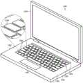
图1A示出了计算设备的简化示例。Figure 1A shows a simplified example of a computing device.
图1B示出了图1A的计算设备的简化功能框图。FIG. 1B shows a simplified functional block diagram of the computing device of FIG. 1A .
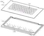
图2A示出了图1A的计算设备的分解图。Figure 2A shows an exploded view of the computing device of Figure 1A.
图2B至图2F示出了沿图1A中的截面A-A观察的图1A的计算设备的一部分的局部剖视图。2B-2F illustrate partial cross-sectional views of a portion of the computing device of FIG. 1A viewed along section A-A in FIG. 1A .
图3A示出了图1A的计算设备的基部部分的分解图。3A shows an exploded view of a base portion of the computing device of FIG. 1A.
图3B示出了沿图1A中的截面B-B观察的图1A的计算设备的基部部分的局部剖视图。3B illustrates a partial cross-sectional view of the base portion of the computing device of FIG. 1A viewed along section B-B in FIG. 1A .
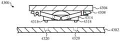
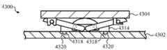
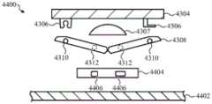
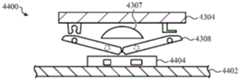
图4A至图5D示出了沿图1A中的截面B-B观察的图1A的计算设备的基部部分的局部剖视图。4A-5D illustrate partial cross-sectional views of the base portion of the computing device of FIG. 1A viewed along section B-B in FIG. 1A .
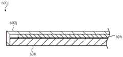
图6A至图6H以及图6J示出了沿图1A中的截面C-C观察的图1A的计算设备的显示部分的局部剖视图。6A-6H and 6J illustrate partial cross-sectional views of the display portion of the computing device of FIG. 1A viewed along section C-C in FIG. 1A .
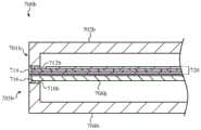
图7A至图7B示出了沿图1A中的截面B-B和C-C观察的图1A的计算设备的局部剖视图。7A-7B illustrate partial cross-sectional views of the computing device of FIG. 1A viewed along sections B-B and C-C in FIG. 1A .
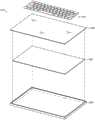
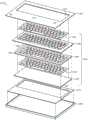
图8A至图8B示出了计算设备的示例性顶壳的分解图。8A-8B illustrate exploded views of an exemplary top case of a computing device.
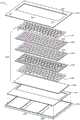
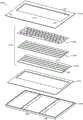
图9A示出了计算设备的另一示例性顶壳的分解图。9A shows an exploded view of another exemplary top case of a computing device.
图9B示出了沿图9A中的截面D-D观察的图9A的顶壳的局部剖视图。FIG. 9B shows a partial cross-sectional view of the top case of FIG. 9A viewed along section D-D in FIG. 9A .
图10示出了计算设备的另一示例性顶壳。10 illustrates another example top case for a computing device.
图11A示出了计算设备的照明基部部分的分解图。11A shows an exploded view of an illuminated base portion of a computing device.
图11B示出了沿图11A中的截面E-E观察的图11A的基部部分的局部剖视图。FIG. 11B shows a partial cross-sectional view of the base portion of FIG. 11A viewed along section E-E in FIG. 11A .
图11C至图11E示出了根据图11A至图11B的示例性照明基部部分。11C-11E illustrate exemplary lighting base portions according to FIGS. 11A-11B.
图11F至图11G示出了示例性照明计算设备。11F-11G illustrate exemplary lighting computing devices.
图11H示出了根据图11F至图11G的示例性照明基部部分。FIG. 11H shows an exemplary lighting base portion according to FIGS. 11F-11G .
图12A示出了具有平坦顶壳的示例性计算设备。Figure 12A shows an example computing device with a flat top case.
图12B示出了图12A的示例性计算设备的基部部分的分解图。12B shows an exploded view of the base portion of the exemplary computing device of FIG. 12A.
图13A示出了具有波状顶壳的示例性计算设备。FIG. 13A illustrates an example computing device with a contoured top case.
图13B示出了图13A的计算设备的示例性基部部分的分解图。13B shows an exploded view of an exemplary base portion of the computing device of FIG. 13A.
图13C示出了图13A的计算设备的另一示例性基部部分的分解图。13C illustrates an exploded view of another exemplary base portion of the computing device of FIG. 13A.
图13D示出了图13A的计算设备的另一示例性基部部分的分解图。13D illustrates an exploded view of another exemplary base portion of the computing device of FIG. 13A.
图13E示出了图13A的计算设备的另一示例性基部部分的分解图。13E shows an exploded view of another exemplary base portion of the computing device of FIG. 13A.
图13F至图13H以及图13J至图13K示出了图13E的基部部分中的部件的示例性布置的局部剖视图。13F-13H and 13J-13K show partial cross-sectional views of exemplary arrangements of components in the base portion of FIG. 13E.
图13L示出了图13A的计算设备的另一示例性基部部分的分解图。13L illustrates an exploded view of another exemplary base portion of the computing device of FIG. 13A.
图13M至图13O示出了图13L的基部部分的示例性板的各部分。13M-13O illustrate portions of an exemplary panel of the base portion of FIG. 13L.
图14A示出了具有波状顶壳的另一示例性计算设备。14A illustrates another example computing device with a contoured top case.
图14B示出了图14A的示例性计算设备的基部部分的分解图。14B shows an exploded view of the base portion of the exemplary computing device of FIG. 14A.
图15A示出了具有波状顶壳的另一示例性计算设备。15A illustrates another example computing device with a contoured top case.
图15B示出了图15A的示例性计算设备的基部部分的分解图。15B shows an exploded view of the base portion of the exemplary computing device of FIG. 15A.
图16A至图16C示出了具有虚拟键盘的示例性计算设备。16A-16C illustrate an example computing device with a virtual keyboard.
图16D至图16G示出了结合键盘附件的图16A至图16C的示例性计算设备。16D-16G illustrate the example computing device of FIGS. 16A-16C in combination with a keyboard accessory.
图17A至图17B示出了图16A至图16C的计算设备的示例性基部部分的分解图。17A-17B illustrate exploded views of an exemplary base portion of the computing device of FIGS. 16A-16C .
图18A至图18B示出了具有触敏输入表面的计算设备的示例性基部部分的局部分解图。18A-18B illustrate partial exploded views of an exemplary base portion of a computing device with a touch-sensitive input surface.
图18C至图18D示出了图18B的触摸传感器的各部分。18C-18D illustrate portions of the touch sensor of FIG. 18B.
图18E至图18F示出了具有触敏输入表面的计算设备的顶壳的其他示例。18E-18F illustrate other examples of top cases for computing devices with touch-sensitive input surfaces.
图19A示出了计算设备的示例性顶壳。Figure 19A illustrates an exemplary top case for a computing device.
图19B至图19D示出了沿图19A中的截面F-F观察的图19A的顶壳的局部剖视图。19B-19D show partial cross-sectional views of the top case of FIG. 19A viewed along section F-F in FIG. 19A .
图20A示出了计算设备的另一示例性顶壳。FIG. 20A illustrates another example top case for a computing device.
图20B至图20C示出了沿图20A中的截面G-G观察的图20A的顶壳的局部剖视图。20B to 20C show partial cross-sectional views of the top case of FIG. 20A viewed along section G-G in FIG. 20A .
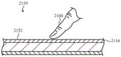
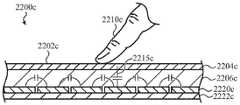
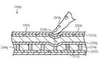
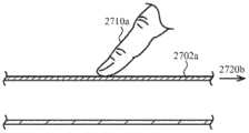
图21A至图21D示出了具有集成力传感器或力感测能力的输入表面的示意图。21A-21D show schematic views of input surfaces with integrated force sensors or force sensing capabilities.
图22A至图22H以及图22J至图22M示出了示例性力传感器。22A-22H and 22J-22M illustrate exemplary force sensors.
图23示出了具有围绕顶壳的周边定位的示例性力传感器的示例性顶壳。FIG. 23 illustrates an example top case with example force sensors positioned around the perimeter of the top case.
图24A和图24B示出了图23的顶壳和力传感器的剖视图。24A and 24B show cross-sectional views of the top case and force sensor of FIG. 23 .
图25示出了具有示例性两层力传感器的顶壳的分解图。Figure 25 shows an exploded view of a top case with an exemplary two-layer force sensor.
图26A至图26B示出了具有触觉致动器的示例性设备。26A-26B illustrate exemplary devices with haptic actuators.
图27A至图27D示出了示例性全局触觉输出。27A-27D illustrate example global haptic outputs.
图28A至图28B示出了示例性局部化触觉输出。28A-28B illustrate example localized haptic outputs.
图29A至图29H以及图29J至图29K示出了示例性触觉设备。29A-29H and 29J-29K illustrate exemplary haptic devices.
图30A至图30B示出了不同触觉设备在示例性顶壳的接触表面上的示例性布置。30A-30B illustrate example placements of different haptic devices on the contact surface of an example top case.
图30C示出了用于顶壳和底壳的示例性接合技术。Figure 30C shows an exemplary joining technique for the top and bottom cases.
图31A至图31B示出了用于文本和/或触摸输入的示例性计算设备。31A-31B illustrate an example computing device for text and/or touch input.
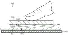
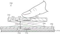
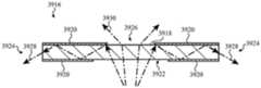
图32A示出了具有手指感测系统的示例性计算设备。Figure 32A illustrates an example computing device with a finger sensing system.
图32B至图32E示出了沿图32A中的截面I-I观察的图32A的计算设备的局部剖视图。32B-32E illustrate partial cross-sectional views of the computing device of FIG. 32A viewed along section I-I in FIG. 32A.
图33A至图33B示出了输入按键的示意图。33A to 33B show schematic diagrams of input keys.
图34A至图34B示出了沿图13A中的截面J-J观察的示例性输入按键的局部剖视图。34A-34B illustrate partial cross-sectional views of exemplary input keys as viewed along section J-J in FIG. 13A.
图35A至图35B示出了沿图13A中的截面J-J观察的另一示例性输入按键的局部剖视图。35A-35B illustrate partial cross-sectional views of another exemplary input key as viewed along section J-J in FIG. 13A.
图36A至图36B示出了沿图13A中的截面J-J观察的另一示例性输入按键的局部剖视图。36A-36B illustrate partial cross-sectional views of another exemplary input key as viewed along section J-J in FIG. 13A.
图37A至图37B示出了沿图13A中的截面J-J观察的另一示例性输入按键的局部剖视图。37A-37B illustrate partial cross-sectional views of another exemplary input key as viewed along section J-J in FIG. 13A.
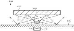
图38示出了沿图13A中的截面J-J观察的具有照明键盘的示例性计算设备的局部剖视图。38 illustrates a partial cross-sectional view of the exemplary computing device with an illuminated keyboard viewed along section J-J in FIG. 13A.
图39A示出了照明键盘的示例性键帽的剖视图。39A shows a cross-sectional view of an example keycap of an illuminated keyboard.
图39B示出了照明键盘的另一示例性键帽的剖视图。39B shows a cross-sectional view of another example keycap of an illuminated keyboard.
图40A示出了沿图13A中的截面J-J观察的具有照明键盘的另一示例性计算设备的局部剖视图。40A illustrates a partial cross-sectional view of another exemplary computing device with an illuminated keyboard, viewed along section J-J in FIG. 13A.
图40B示出了图40A的顶壳的顶视图。Figure 40B shows a top view of the top case of Figure 40A.
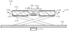
图41A示出了沿图13A中的截面J-J观察的具有照明键盘的另一示例性计算设备的局部剖视图。41A illustrates a partial cross-sectional view of another exemplary computing device with an illuminated keyboard, viewed along section J-J in FIG. 13A.
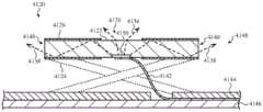
图41B示出了沿图13A中的截面J-J观察的具有照明键盘的另一示例性计算设备的局部剖视图。41B illustrates a partial cross-sectional view of another exemplary computing device with an illuminated keyboard, viewed along section J-J in FIG. 13A.
图41C示出了沿图13A中的截面J-J观察的具有照明键盘的另一示例性计算设备的局部剖视图。41C illustrates a partial cross-sectional view of another exemplary computing device with an illuminated keyboard, viewed along section J-J in FIG. 13A.
图42A至图42B示出了沿图13A中的截面J-J观察的具有照明键盘的另一示例性计算设备的局部剖视图。42A-42B illustrate partial cross-sectional views of another exemplary computing device with an illuminated keyboard viewed along section J-J in FIG. 13A.
图42C示出了沿图13A中的截面J-J观察的具有照明键盘的另一示例性计算设备的局部剖视图。42C illustrates a partial cross-sectional view of another exemplary computing device with an illuminated keyboard viewed along section J-J in FIG. 13A.
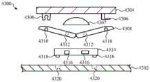
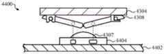
图43A至图43C示出了计算设备的示例性按键的剖视图。43A-43C illustrate cross-sectional views of example keys of a computing device.
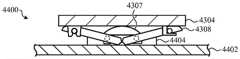
图44A至图44D示出了计算设备的另一示例性按键的剖视图。44A-44D illustrate cross-sectional views of another example key of a computing device.
图45A示出了计算设备的另一个示例性按键的剖视图。45A illustrates a cross-sectional view of another example key of a computing device.
图45B示出了计算设备的另一个示例性按键的剖视图。45B illustrates a cross-sectional view of another example key of a computing device.
图46示出了计算设备的另一个示例性按键的剖视图。46 illustrates a cross-sectional view of another example key of a computing device.
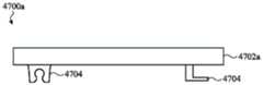
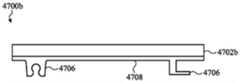
图47A至图47B示出了示例性键帽的侧视图。47A-47B illustrate side views of exemplary keycaps.
图48A至图48F示出了接收各种触摸输入的示例性计算设备。48A-48F illustrate an example computing device receiving various touch inputs.
图49A至图49B示出了与外部对象交互的示例性计算设备。49A-49B illustrate an example computing device interacting with external objects.
图50示出了电子设备的示意图。Figure 50 shows a schematic diagram of an electronic device.
具体实施方式Detailed ways
现在将具体地参考在附图中示出的代表性实施方案。应当理解,以下描述不旨在将实施方案限制于一个优选实施方案。相反,其旨在涵盖可被包括在由所附权利要求书限定的所述实施方案的实质和范围内的另选形式、修改形式和等同形式。Reference will now be made in detail to the representative embodiments illustrated in the accompanying drawings. It should be understood that the following description is not intended to limit the embodiments to one preferred embodiment. On the contrary, it is intended to cover alternatives, modifications and equivalents, which may be included within the spirit and scope of the described embodiments as defined by the appended claims.
本文所述的实施方案整体涉及一种便携式电子设备(例如,便携式计算机、笔记本计算机、膝上型计算机等),该便携式电子设备具有由介电材料诸如塑料、陶瓷、玻璃、复合材料或它们的组合形成的壳体的上部。由介电材料形成的部件可限定用于容纳便携式设备的各种部件的壳体的内部体积的一部分,并且还可限定允许多种触摸和键盘输入的集成接口系统的输入表面。具体地,集成接口系统可用作触控板、键盘,或可提供触控板和键盘功能,并且介电部件可限定键盘区域和触控板区域的全部或一部分。Embodiments described herein generally relate to a portable electronic device (e.g., portable computer, notebook computer, laptop computer, etc.) having a Combined to form the upper part of the housing. The components formed from the dielectric material may define a portion of the interior volume of the housing for housing the various components of the portable device, and may also define an input surface for an integrated interface system allowing various touch and keyboard inputs. Specifically, the integrated interface system can function as a touchpad, a keyboard, or can provide both touchpad and keyboard functionality, and the dielectric member can define all or a portion of the keyboard area and the touchpad area.
在本文所述的一些实施方案中,集成接口系统可与多个传感器集成,包括触摸传感器和力传感器,这些传感器可以检测施加到输入表面的各种区域的各种类型的输入。在一些情况下,触摸传感器和/或力传感器被形成为统一结构,该统一结构被配置为检测施加到非键盘区域的触摸输入以及施加到键盘区域(其可包括机械按键和/或虚拟按键)的按键输入。根据本文所述的实施方案,集成接口系统还可用于检测施加到机械键盘的键帽的手势和多点触摸输入,从而允许键帽和键盘区域用作触控板。In some embodiments described herein, the integrated interface system can be integrated with multiple sensors, including touch sensors and force sensors, that can detect various types of input applied to various areas of the input surface. In some cases, the touch sensor and/or force sensor is formed as a unified structure configured to detect touch input applied to non-keyboard areas as well as to areas of the keyboard (which may include mechanical keys and/or virtual keys) key input. According to embodiments described herein, the integrated interface system can also be used to detect gestures and multi-touch input applied to the keycaps of a mechanical keyboard, allowing the keycaps and keyboard area to function as a touchpad.
集成接口系统还可提供各种类型的输出功能,包括视觉输出、触觉输出等。例如,示能表示(例如,按键、键盘、按钮、滑块、拨号盘等)的图像可显示在顶壳上(例如,利用显示设备),以指示可在何处提供触摸输入或力输入。又如,集成接口系统的顶壳可被配置为响应于检测到触摸输入或力输入而移动或振荡以提供触觉输出。因此,集成接口系统可经由集成输入/输出表面提供综合输入和输出功能。The integrated interface system can also provide various types of output functions, including visual output, tactile output, and so on. For example, images of affordances (eg, keys, keypads, buttons, sliders, dials, etc.) may be displayed on the top case (eg, with a display device) to indicate where touch or force input may be provided. As another example, the top case of the integrated interface system may be configured to move or oscillate in response to detecting a touch input or force input to provide a tactile output. Thus, the integrated interface system can provide integrated input and output functionality via the integrated input/output surface.
如上所述,限定集成接口系统的输入表面的部件可由介电材料诸如玻璃、塑料或陶瓷的连续和/或无缝片材形成(例如,其可以是单个玻璃构件)。该片材可具有能够实现本文所述的各种输入和输出功能的特性。例如,该片材可以是牢固的且可具有高抗刮擦性,并且可提供与其他材料或部件相比具有优异外观和/或触感的表面光洁度。该片材也可以是介电的和/或基本上不导电的,从而允许通过该片材检测触摸输入和力输入,并且允许电磁波和/或场(例如,射频信号、感应电力、感应信号和其他无线通信或电磁能量传输)在没有大量衰减的情况下通过。该片材可以是连续的或无缝的,这可有助于防止液体或其他外来碎屑进入。该片材也可以是透光的,以允许可通过其看到图像或光。如本文所用,透光可用于指透明或半透明的事物,或者以其他方式允许光通过其传播。在一些情况下,透明材料或部件可引入一些漫射,透镜效应,扭曲等(例如,由于表面纹理),同时仍允许通过材料或部件看到对象或图像,并且此类偏差被理解为在透明的含义范围内。另外,透明的材料可被涂覆,涂漆或以另外方式处理以产生非透明的(例如不透明的)部件;在此类情况下,材料仍可称为透明的,即使材料可以是不透明部件的一部分。半透明部件可通过在另外的透明材料(例如,透明玻璃)上产生纹理化或磨砂的表面来形成。也可使用半透明材料,诸如半透明聚合物,半透明陶瓷等。As noted above, the components defining the input surface of the integrated interface system may be formed from a continuous and/or seamless sheet of dielectric material such as glass, plastic, or ceramic (eg, it may be a single glass member). The sheet can have properties that enable the various input and output functions described herein. For example, the sheet can be strong and can have high scratch resistance, and can provide a surface finish that has a superior appearance and/or feel compared to other materials or components. The sheet may also be dielectric and/or substantially non-conductive, allowing detection of touch and force inputs through the sheet, and allowing electromagnetic waves and/or fields (e.g., radio frequency signals, induced electric forces, induced signals, and other wireless communications or transmission of electromagnetic energy) pass without substantial attenuation. The sheet can be continuous or seamless, which can help prevent the ingress of liquids or other foreign debris. The sheeting may also be light transmissive to allow images or light to be seen through it. As used herein, light transmissive may be used to refer to something that is transparent or translucent, or otherwise allows light to travel therethrough. In some cases, transparent materials or components may introduce some diffusion, lensing, distortion, etc. (e.g., due to surface texture) while still allowing objects or images to be seen through the material or component, and such deviations are understood to be within the scope of meaning. Additionally, a transparent material may be coated, painted, or otherwise treated to produce a non-transparent (e.g., opaque) part; in such cases, the material may still be referred to as transparent even though the material may be an opaque part part. Translucent components may be formed by creating a textured or frosted surface on an otherwise transparent material (eg, clear glass). Translucent materials such as translucent polymers, translucent ceramics, etc. may also be used.
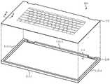
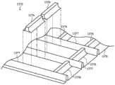
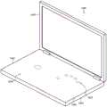
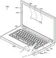
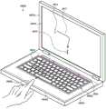
图1示出了可包括如上所述的集成接口系统的计算设备100(或简称为“设备100”)。具体地,设备100的基部部分104可包括顶壳112,该顶壳限定壳体的一部分并且还形成或是本文所述的集成接口系统的一部分。1 illustrates a computing device 100 (or simply "
设备100可以是或可类似于便携式计算机(也被称为笔记本或膝上型计算机),该便携式计算机具有显示部分102和基部部分104,该基部部分灵活地或枢转地联接到显示部分102(例如,使得显示部分102能够相对于基部部分104旋转、枢转、挠曲、进行关节运动或以其他方式运动)。显示部分102包括显示器(也被称为主显示器),该显示器诸如通过显示图形用户界面来提供向用户传送视觉信息的主要方式。基部部分104被配置为接收各种类型的用户输入,诸如键盘输入(例如,键入)、触摸输入(例如,手势、多点触摸输入、轻扫、轻击等)等。基部部分104还可提供用于向用户传递信息的输出,诸如利用指示器灯、触觉输出设备、安装在基部部分104中的显示器等。在一些情况下,通过在基部部分104上使用连续顶表面来有利于或实现经由基部部分104提供各种类型的输入和输出,如本文所述。
显示部分102和基部部分104可彼此联接,使得它们可以定位在打开位置和闭合位置。在打开位置,用户可以能够经由基部部分104提供对设备100的输入,同时在显示部分102上查看信息。在闭合位置,显示部分102和基部部分104抵靠彼此折叠。更具体地,显示部分102和基部部分104可铰接在一起(例如,经由枢轴机构或铰链103),以形成可以在打开构型和闭合构型之间移动的翻盖式设备。The
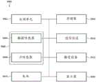
可在显示部分102和基部部分104之间传输信息和/或数据。例如,可将显示数据诸如使显示部分102显示图像、用户界面、应用程序数据等的数据或信号从基部部分102发送到显示部分104。类似地,可将输入数据从显示部分102发送到基部部分104。输入数据可包括与施加到显示部分102内的触摸屏的触摸输入有关的数据、传感器数据(例如,来自显示部分102中的传感器,诸如光传感器、加速度计等)、相机数据(例如,来自显示部分102中的相机)等。电子设备100可包括用于在显示部分102和基部部分104之间传输数据的任何适当的通信系统,诸如有线或无线通信系统。无线通信系统可包括显示部分102中的第一发射器/接收器,以及基部部分104中与第一发射器/接收器进行通信的第二发射器/接收器。第一发射器/接收器和第二发射器/接收器可以任何合适的方式进行通信并使用任何合适的一个或多个无线频(例如,2.4GHz、60GHz)、通信协议等。第一发射器/接收器和第二发射器/接收器也可经由光通信链路进行通信。Information and/or data may be transferred between the
也可在基部部分104和显示部分102之间传输电力。例如,基部部分104和显示部分102中的任一者或两者可包括电池或其他电源。可以基于每个部分的电力需求和电力供应根据需要将电力从一个部分发送到另一个部分。例如,基部部分104和显示部分102可包括电池以及需要电力的部件。无论电池或电路或部件的位置如何,都可以将电力从任何电池分配到需要电力的任何电路或部件。可使用任何合适的部件和技术在基部部分104和显示部分102之间传输电力。例如,有线或物理电力连接可将显示部分102联接到基部部分104。又如,可诸如经由电感或电容电力传输系统无线地传输电力。Power may also be transferred between the
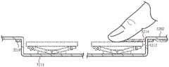
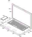
如上所述,基部部分104可包括顶壳112。顶壳112可限定或可以是设备100的集成接口系统的一部分。例如,顶壳112可限定基部部分104的顶部外表面,并且可被配置为接收触摸输入、力输入、键盘输入等。在一些情况下,顶壳112的整个顶表面(或基本上所有顶表面)可以是触摸敏感的和/或力敏感的,并且可沿着其顶表面的基本上任何位置(包括键盘区域以及周围区域)检测触摸输入。在整个顶壳112是触摸敏感的和力敏感的情况下,经由顶壳112实现多种类型的输入。例如,如本文所述,可将触摸输入包括光标控制手势施加在顶壳上的任何位置,包括虚拟键盘或机械键盘的按键上。又如,在键盘区域以及非键盘区域上添加力感测可有利于在多个手指停留在虚拟键盘时检测键入输入,因为力感测系统可允许设备区分停留在按键上的手指与实际轻击或按压按键的手指。As mentioned above, the
除了接收或检测输入之外,顶壳112可被配置为向用户提供输出。例如,顶壳112可包括显示器、光源、触觉致动器等或与这些部件集成,这些部件提供可经由顶壳112检测的输出(例如,在沿着顶壳112的顶表面的任何位置或基本上任何位置)。更具体地,显示器可被配置为在顶壳112上产生图像,并且触觉致动器可被配置为以可由与顶壳112接触的用户检测的方式来移动顶壳112。顶壳112的组成和构型可有利于并集成这些(及其他)输入和输出功能。例如,连续的非导电顶壳112(例如,由电介质诸如玻璃、塑料、陶瓷、复合材料或材料的组合形成)可允许通过顶壳112检测输入,同时还提供用于触觉和视觉输出的有效平台。In addition to receiving or detecting input,
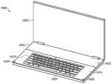
顶壳112可限定或包括输入区域,诸如键盘区域114和触摸输入区域116。键盘区域114可对应于或包括虚拟键盘或机械键盘。本文相对于图16A至图17B讨论了虚拟键盘,并且本文相对于图12A至图15B以及图33A至图43C讨论了机械键盘。The
顶壳112可限定基部部分104的连续顶表面,该连续顶表面可以是基部部分104的顶部外表面。连续顶表面(更一般地讲,连续顶壳)可指不具有接缝、开口、通孔或其他中断部分的表面或构件。因此,在顶壳112的情况下,连续顶壳或连续顶表面可在顶壳112的形成基部部分104的外部顶表面的部分中不具有接缝、开口、通孔或其他中断部分。更具体地,顶壳112可不具有用于按键、键盘、触控板、按钮等的开口。顶壳112可基本上延伸到基部部分104的外边缘。因此,顶壳112可防止或减少液体、灰尘、污垢或其他污染物或碎屑通过顶壳112的顶表面进入基部部分104的可能性。而且,连续表面提供期望的具有美感且为触敏的触觉和视觉输出表面,该输出表面可以利用顶壳112的整个暴露的顶表面。The
顶壳112可由透光材料诸如玻璃、塑料或透光陶瓷形成,或者包括这些透光材料。在一些情况下,顶壳112是单个构件,诸如单个玻璃构件、单个塑料构件,或者由任何其他合适的材料形成或包括任何其他合适的材料的单个构件。在其他情况下,顶壳112可由相同材料或不同材料的多个构件形成,这些构件粘结、粘附、接合或以其他方式联接在一起以限定顶壳112。The
在一些情况下,顶壳112的全部或一部分可被掩蔽以形成不透明区域。可使用任何合适的技术形成掩模,诸如沉积油墨、染料、膜或以其他方式将不透明材料定位在顶壳112下方(以及旨在保持隐藏或封闭的任何其他部件或层上方)。掩模或者其他不透明材料或层可以是任何所需的颜色。实际上,因为顶壳112可以是透光的(例如,透明的),所以对可实现的颜色的限制可能比常规设备的限制要少。例如,某些颜色、饰面或其他光学处理可能难以或不可能在未涂覆的不透明塑料材料中实现。通过使用透光或透明的顶壳112,可以实现具有更多可用颜色和/或饰面(例如,镜面饰面、金属薄片饰面等)的设备。在一些情况下,图像、照片、绘画或其他图形内容可透过透光顶壳112看到。In some cases, all or a portion of
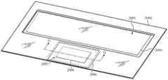
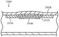
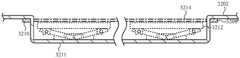
触摸输入区域116可被配置为检测基于触摸和/或基于力的输入,并且可以是或可包括顶壳112的任何部分,包括基本上整个顶壳112,包括键盘区域114、触控板区域(例如,图20A的触控板区域2003)、虚拟按键区域(例如,图12A的虚拟按键区域1208)、顶壳的任选侧壁(例如,图5A至图5C的侧壁512a-c)或顶壳112的任何其他部分。在一些情况下,从边缘到边缘的基本上整个顶壳112可限定触敏输入区域。这样,并且如本文所讨论的,可在顶壳112的任何部分上(包括在键盘区域114内)检测触摸或触控板输入,诸如点击、轻击、手势(例如,轻扫、捏合)和多点触摸输入。此外,即使在键盘区域114包括机械按键机构的情况下,触摸输入区域116也可检测施加到键帽而不是直接施加到顶壳112的触摸输入(例如,手势)。如本文所用,“按键”可指机械按键、虚拟按键(例如,下面显示器所显示的按键)、按键区域(例如,由顶壳上的掩模层限定),或本文所述的任何其他合适类型的按键以及任何相关联的机构、键帽或支撑结构。
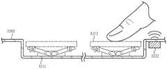
设备100尤其是顶壳112还可包括或限定输出区域,诸如视觉输出区域和触觉输出区域。触觉输出区域包括顶壳112的移动或以其他方式在用户中引起触觉感觉的区域。视觉输出区域包括产生视觉输出的区域,诸如与灯或显示器相关联(例如,显示虚拟按键和/或动态按键)的区域。本文描述了示例性视觉和触觉输出区域以及用于产生视觉和触觉输出的部件。
因此,设备100可包括限定集成接口系统的顶壳,该集成接口系统提供各种输入和输出功能,包括键盘输入、触摸输入、视觉输出和触觉输出。Accordingly,
图1B是示出示例性集成接口系统118的功能方面的简化框图。集成接口系统118的功能可由本文所述的任何部件和结构来执行,包括触摸传感器、力传感器、触觉致动器、显示器、机械按键、光源等,本文对其示例进行了描述。FIG. 1B is a simplified block diagram illustrating functional aspects of an example integrated
参考图1B,集成接口系统118提供键盘输入功能120。键盘输入功能120包括检测基于按键的输入或类似输入,包括通常经由键盘提供的输入(例如,字母数字和/或符号字符输入、功能按键选择、箭头按键选择)。设备(例如,设备100)可使用任何合适的一个或多个输入机构来执行键盘输入功能120,诸如机械按键、触摸传感器、力传感器、显示器等。在设备包括机械按键或按键机构的情况下,键盘输入功能120包括检测按键机构的物理移动。在设备包括虚拟按键的情况下,键盘输入功能120可包括检测虚拟按键上的触摸输入或力输入。在任一种情况下,键盘输入功能120可通过输入表面(诸如图1A中的顶壳112)检测键盘输入。Referring to FIG. 1B ,
集成接口系统118还提供触摸输入功能122。触摸输入功能122包括检测基于触摸的输入,诸如点击、轻击、手势(例如,轻扫、捏合)、多点触摸输入等。这些输入可类似于或包括通常由触控板检测的输入。例如,这些输入可包括可用于控制设备的显示器上的图形用户界面的光标或元素的手势输入。设备(例如,设备100)可使用任何合适的一个或多个输入机构(诸如电容触摸传感器、电阻触摸传感器、声波传感器等)来执行触摸输入功能122。此类机构可与顶壳112的整个面向用户的部分相关联或基本上覆盖该部分。这样,触摸输入功能122可以检测施加在顶壳112上的任何位置(包括例如机械或虚拟键盘上、机械或虚拟键盘下方的触控板区域上,和/或顶壳的与机械或虚拟键盘的横向侧相邻的部分上)的触摸输入。
触摸输入功能122可包括检测在顶壳112的键盘区域(例如,图1A的键盘区域114)中接收的触摸输入。键盘区域可对应于虚拟键盘的无按键表面,或者其可对应于顶壳112的包括机械按键的区域,如上所述。在任一种情况下,触摸输入功能122可包括检测触摸输入,诸如施加到键盘区域的点击、轻击、手势(例如,轻扫、捏合)和多点触摸输入。在使用机械按键或按键机构的情况下,触摸输入功能122可包括通过机械按键或机构检测触摸输入。The
触摸输入功能122还可包括检测施加到顶壳112的非按键区域的触摸输入。例如,顶壳112的不对应于键盘区域的任何区域(非键盘区域)可被配置为接收触摸输入,并且设备也可检测这些区域中的触摸输入。The
集成接口系统118还提供力输入功能128,该力输入功能包括检测力输入和/或触摸输入的力分量。设备(例如,设备100)可使用任何合适的力传感器来提供力输入功能128,诸如本文相对于图21A至图24B所述的力传感器。力输入功能128可包括检测顶壳112上的任何位置处的力输入。例如,顶壳112的基本上整个顶表面可被配置为接收和/或检测施加到顶壳112的顶表面的基本上任何位置的力输入。此外,在顶壳112包括介电表面或由介电片材(例如,玻璃、塑料、陶瓷等)形成的情况下,介电材料的介电特性和/或机械特性(或其他特性)可有利于检测顶壳上的任何合适的位置处(例如,键盘区域114、非键盘区域或任何其他合适的位置中)的力输入。
集成接口系统118还提供显示功能130,该显示功能包括经由顶壳112输出图像或其他视觉信息。例如,设备(例如,设备100)可包括设备100内的显示器或与所述显示器通信,所述显示器产生可在顶壳112上看到的图像,从而提供显示功能130。显示器可用于例如产生键盘区域114的按键(或其他示能表示)的图像。显示器还可用于在顶壳112上的任何位置限定输入区域、按钮或其他示能表示(例如,以指示输入的位置和/或功能),或显示其他图形对象(例如,图像、视频、文本、用户界面等)。因为顶壳112可由玻璃或其他透明材料形成,所以显示器可与顶壳112集成,使得即使在常规计算设备中不透明的表面(诸如触控板或毗邻键盘的部分)上,顶壳112也充当屏幕。The
集成接口系统118还提供触觉输出功能132,该触觉输出功能包括在顶壳112处产生触觉输出。设备(例如,设备100)可使用触觉致动器(诸如本文参考图25至图30B所讨论的那些触觉致动器)来执行触觉输出功能132。触觉致动器可联接到顶壳112或以其他方式使顶壳112物理地移动,以在顶壳112处产生触觉输出。触觉输出可用于各种目的,诸如以指示设备100已经检测到触摸输入(例如,按键选择或触控板选择)。
集成接口系统118还提供照明功能134,该照明功能包括照明顶壳112的区域或元素。设备(例如,设备100)可使用光源(诸如本文参考图37A至图40B所讨论的那些光源)来提供照明功能。例如,玻璃、塑料或以其他方式透光的顶壳(例如,顶壳112)可用作光导。例如,玻璃或透光(例如,透明或半透明)顶壳112可用作光导以将来自光源的光引导到设备100的其他区域,诸如键帽或其他按键机构下方或周围的区域。而且,在顶壳112是完全透明的或具有透明部分的情况下,透明部分允许来自下面显示器的图像穿过顶壳112,这对于不透明的顶壳将是不可能的。照明功能134还可为显示器提供背光源或其他照明。The
集成接口系统118还提供一个或多个附加输入和/或传感器功能129。设备(例如,设备100)可使用任何合适的部件来接收输入(例如,来自用户或另一计算机、设备、系统、网络等)或检测设备的任何合适的属性或参数、设备周围的环境、与设备交互(或设备附近)的人或物等。例如,设备可包括加速度计、温度传感器、位置/取向传感器、生物识别传感器(例如,指纹传感器、光谱仪、血氧传感器、血糖传感器等)、眼睛跟踪传感器、视网膜扫描仪、湿度传感器、按钮、开关、眼睑闭合传感器等。此类传感器和/或输入设备可位于设备的任何合适的部分或设备中的任何合适的位置。例如,传感器和/或输入设备可位于显示部分102或基部部分104中(或其可包括显示部分102和基部部分104两者中的部件)。输入和/或传感器功能129可使用网络和/或通信系统来提供输入和/或感测功能,诸如从其他设备或系统接收命令、数据、信息、内容(例如,音频、视频、图像、网页)等。The
图2A是设备100的局部分解图。如上所述,设备100包括顶壳112,该顶壳形成限定基部部分104的壳体的一部分,并且还限定基部部分104的顶部外表面,该顶部外表面还可充当用于接收用户输入的集成接口系统的输入表面。如图2A所示,基部部分104枢转地联接到显示部分102,以形成可折叠或翻盖型笔记本计算机。FIG. 2A is a partially exploded view of
如图2A所示,显示部分102包括联接到显示器外壳108的显示器204。显示器204可包括各种显示部件,诸如液晶显示器(LCD)部件、光源(例如,发光二极管(LED)、有机LED(OLED))、滤光器层、偏振器、光漫射器、覆盖件(例如,玻璃或塑料覆盖片)等。更具体地,在一些情况下,显示器204包括显示器叠层(包括例如LCD、偏振膜、光漫射膜和/或背光源或侧光源)以及设置在显示器叠层上方并形成显示器204的面向用户的外部表面的覆盖件。在其他情况下,显示器204包括如上所述的显示器叠层,但不包括单独的覆盖件。在此类情况下,显示器叠层的LCD面板的侧面或表面可形成显示器204的面向用户的外部表面。显示部分102还可包括其他部件,诸如支撑任何前述部件、电池、有线或无线通信部件、处理器、存储器等的结构部件。As shown in FIG. 2A ,
显示部分102可包括联接到显示部分103或与其一体形成的机构102或其部分。例如,显示器外壳108可包括焊接、钎焊、粘附或以其他方式附接到显示器外壳108的铰链(或其部分)。显示器204和顶壳112可包括特征部206(诸如图2A所示的凹口),以允许放置机构103,同时允许显示器204和顶壳112基本上限定显示部分102和基部部分104的整个用户接口表面。
基部部分104可包括底壳110和顶壳112,如上所述,它们一起限定基部部分104的内部体积。基部部分104还可包括内部体积内的部件208,诸如处理器、存储器设备、电路板、输入/输出设备、触觉致动器、有线和/或无线通信设备、通信端口、盘驱动器等。如上所述,顶壳112可以是连续表面(例如,在其顶表面中没有孔或开口),以防止或限制液体、碎屑或其他污染物进入内部体积中,由此降低对部件208的损坏的可能性。The
底壳110可包括底部构件111以及一个或多个侧壁113-1至113-4。在一些情况下,底壳110具有一个、两个、三个或四个侧壁。在底壳具有三个侧壁的情况下,可省略侧壁113-3。在底壳具有两个侧壁的情况下,可省略侧壁113-2、113-4。在底壳具有一个侧壁的情况下,唯一的侧壁可以是侧壁113-1。当然,侧壁的其他构型也是可能的。The
底壳110可由任何合适的材料形成或包括任何合适的材料。例如,底壳110可由金属(例如,钢、铝、钛)、玻璃、塑料、陶瓷、复合材料或任何其他合适的其他材料或者这些材料或其他材料的组合形成,或包括这些材料。在一些情况下,底壳110是单个(例如,整体)部件或构件,诸如单片玻璃、金属、塑料等。例如,底壳110可以是由单件金属形成的单个部件,并且可通过压印、拉伸、机加工、液压成形、模塑或任何其他合适的工艺形成。在底壳110是单个部件的情况下,底部构件111和侧壁113可以是一体结构(例如,整体部件)。The
顶壳112可以任何合适的方式联接到底壳110。本文描述了顶壳112和底壳110之间的联接的各种示例,以及顶壳112和底壳110的各种构型和形状。类似地,本文描述了显示器204和显示器外壳108的示例性构型(以及用于接合它们的技术)。
图2B至图2F是沿图1A中的截面A-A观察的基部部分104的剖视图,其示出了部件208在基部部分104内的示例性放置。如图2B所示,部件208b可联接到底壳110。部件208b中的一些可接触顶壳112而不附接或固定到顶壳112。另选地,部件208b可通过空间或材料层与顶壳112分离,或者它们可联接到顶壳的底部内表面和底壳的顶部内表面两者。2B-2F are cross-sectional views of
在图2C所示的另一个示例中,部件208c可联接到顶壳112。部件208c可被设置为与底壳110分开一定空间(如图所示),或者一些或所有部件208c可接触底壳110而不附接或固定到底壳110。In another example shown in FIG. 2C ,
在图2D所示的另一个示例中,第一部件210(例如,图2A的部件208的第一子集)可联接到顶壳112,而第二部件212(例如,图2A的部件208的第二子集)可联接到底壳110。第一部件210可包括有利于经由顶壳112的输入和输出功能的部件,诸如触觉致动器、显示器、触摸传感器、力传感器等。第二部件212可包括其他部件,诸如电池、处理器、电路板、通信端口等。还设想了其他部件分布和构型。In another example shown in FIG. 2D , first components 210 (eg, a first subset of
第一部件210和第二部件212可被定位成使得它们在组装时不会彼此干扰。例如,如图2D所示,第二部件212被配置为适配在限定在第一部件210之间的空间中。这允许有效利用基部部分104的内部体积,并且与其他部件放置相比可减小基部部分104的一个或多个尺寸(例如,高度)。The
图2E示出了图2D的示例性部件布置,其中灌封材料211设置在顶壳110和底壳112之间并且填充部件210、212之间的空间。灌封可用于指作为液体、泡沫或其他可流动状态设置在体积或区域中,然后固化成不可流动状态(例如,固体)的材料。灌封可由绝缘或介电材料形成,以防止内部电子部件的短路或干扰。示例性灌封材料包括但不限于聚氨酯、有机硅、环氧树脂等。FIG. 2E shows the exemplary component arrangement of FIG. 2D , where
灌封材料211可支撑顶壳112并且可有助于减少或防止顶壳112响应于所施加的力(诸如与触摸输入、力输入、键盘输入、触控板输入、停留在顶壳112上的手相关联的力)而发生偏转。灌封材料211可以是任何合适的材料,诸如有机硅、环氧树脂、聚氨酯、气凝胶或者任何其他合适的聚合物或其他材料。图2E示出了灌封材料211占据顶壳110和底壳112之间的所有其他空的空间。在其他示例(诸如如图2F所示的示例)中,灌封材料211可占据小于所有其他空的空间,使得间隙、开口、气穴/气泡、腔体等存在于基部部分104中。在此类情况下,在基部部分104中可存在多个离散块或体积的灌封材料211(例如,柱214)。The
部件208b、208c、210和212可对应于图2A所示的部件208,或者它们可以是不同的部件。而且,图2B至图2F中所示的部件的放置仅仅是示例,也可使用部件的其他构型和布置。例如,一些部件(或其部分)可定位在顶壳112和底壳110之间,而不接触顶壳112的底部内表面或底壳110的顶部内表面。例如,此类部件可联接到底壳110的侧表面或侧壁。
图3A是基部部分104的局部分解图,其示出了顶壳112与底壳110分离。图3B是沿图1A和图3A中的截面B-B观察的基部部分104的局部剖视图。为了清楚起见,图3A至图3B省略了设备100的设置在顶壳112和底壳110之间的内部空间中的部件208(图2A)。如图所示,顶壳112联接到底壳110以限定基部部分104的内部体积300。图3A至图3B是顶壳112和底壳110的结构整合的示意图,而图4A至图5D示出了几个示例性实施方案。FIG. 3A is a partially exploded view of
图4A是沿图3A中的截面B-B观察的计算设备的基部部分400a(其可对应于图1A的基部部分104)的局部剖视图,其示出了底壳406a和顶壳404a(其可分别对应于底壳110和顶壳112)的示例性构型。顶壳404a可经由底壳406a的侧壁附接到底壳406a。例如,顶壳404a的底表面405a的一部分经由接合构件414联接到底壳406a的侧壁410a的顶部。如图所示,顶壳404a可延伸到底壳406a的外边缘,并且顶壳404a的边缘或侧面408可形成基部部分400a的侧面的一部分。顶壳404a可具有从顶壳404a的顶表面407a到顶壳404a的边缘或侧面408的圆形或波状过渡部分(例如,圆角或圆边)。圆形或波状过渡部分可限定光滑连续表面的一部分,该光滑连续表面包括圆形或波状过渡部分和底壳406a的侧面的至少一部分。在其他情况下,顶壳404a可具有任何其他合适的形状,诸如基本上垂直的角度(如图所示)、斜面化边缘等。圆边或斜面化边缘可抵抗顶壳404a的破碎、开裂或其他损坏,并且还可为基部部分400a提供具有吸引力或期望的外观和触感。4A is a partial cross-sectional view of the
接合构件414可以是任何适合的材料或材料组合。接合构件414可以是粘合剂,诸如压敏粘合剂(PSA)、热敏粘合剂(HSA)、环氧树脂、氰基丙烯酸酯或任何其他合适的粘合剂。除了将顶壳404a固定到底壳406a之外,接合构件414还可充当顶壳404a和底壳406a之间的密封件,从而防止材料(例如,液体、灰尘或其他污染物)进入基部部分400a。
在一些情况下,接合构件414可以是基本上刚性的,使得当将力(例如,由于键入或施加到顶壳404a的其他输入力)施加到顶壳404a时,顶壳404a和底壳406a的接合表面之间的距离基本上不会改变。另选地,接合构件414可由柔顺材料形成或可包括柔顺材料,诸如泡沫、橡胶、聚氨酯或允许顶壳404a响应于在顶壳404a和/或底壳406a上施加力而相对于底壳406a移动的其他合适的材料。此类力可响应于用户输入(例如,键入或与触控板交互),它们可由触觉致动器产生,它们可能是由于设备掉落或物体掉落在设备上等。此外,此类力可以是压缩力或张力、剪切力等。如本文所述,柔顺材料可用于接合构件414,以便允许触觉致动器更容易地相对于底壳406a移动顶壳404a(与更刚性的接合构件相比),从而在通过顶壳404a将触觉输出传输给用户时提供更高的效率。In some cases,
可使用柔顺接合构件414,其中力传感器基于顶壳404a相对于底壳406a的偏转量或移动量来确定施加到顶壳404a的力的大小。此类力传感器或其部件可结合到接合构件414中。例如,用于检测由于顶壳404a相对于底壳406a的偏转而引起的电容变化的电极可包括在接合构件414中。A
接合构件414可以是单件材料(例如,单层粘合剂),或者其可包括多个部件、层或其他元件。例如,多层接合构件414可包括定位在两个粘合剂层之间(并粘结到两个粘合剂层)的柔顺构件,其中第一粘合剂层粘结到顶壳404a,并且第二粘合剂层粘结到底壳406a。接合构件的一部分可形成基部部分的侧面(例如,外表面)的一部分,如图4A所示。Joining
如图4A所示,底壳406a包括远离底部构件412a(或从该底部构件向上,如图4A所示)延伸的侧壁410a(其可类似于图3A至图3B的底部构件111或者是该底部构件的实施方案)。因此,底壳406a限定基部部分400a的内部体积的至少底部和侧面,并且顶壳404a限定内部体积的顶部。在一些情况下,底壳(例如,底壳406a)包括限定设备的基部部分的外侧和/或侧表面的多个侧壁。例如,图3A示出了包括围绕基部部分的前侧、左侧、右侧和后侧区域延伸的第一侧壁、第二侧壁、第三侧壁和第四侧壁的底壳110。侧壁可与底壳的底部构件(例如,底部构件412a)一体形成。底壳(例如,底壳110、406a,或本文所述的任何其他底壳)可由单件金属、玻璃、陶瓷等形成。在一些情况下,底壳(包括底表面和一个、两个、三个或四个侧壁)可以是金属构件,该金属构件可由单件金属机加工或以其他方式形成。其他构型也是可能的,诸如其中顶壳限定内部体积的顶部和侧面并且底壳限定内部体积的底部的构型。本文讨论了此类构型的示例。As shown in FIG. 4A , the
顶壳404a、底壳406a和接合构件414可具有基本上相似的外观。例如,这些部件可被配置为具有相同或相似的颜色、纹理、触感等。这可包括向部件施加油漆、油墨、染料或其他涂层,并且/或者向部件施加相同的修整工艺(例如,机加工、抛光等)。The
图4B是沿图3A中的截面B-B观察的计算设备的基部部分400b(其可对应于图1A的基部部分104)的局部剖视图,其示出了底壳406b和顶壳404b的另一个示例性构型。顶壳404b和底壳406b各自限定对应的阶梯式接口区域。具体地,顶壳404b可限定第一接口表面420以及与第一接口表面420偏离(例如,不在同一平面中)的第二接口表面422。相应地,底壳406b可限定与第一接口表面420相对的第三接口表面424,以及与第二接口表面422相对的第四接口表面426。4B is a partial cross-sectional view of the
第一接口表面420和第三接口表面424可经由第一接合构件416彼此联接,并且第二接口表面422和第四接口表面426可经由第二接合构件418彼此联接。第一接合构件416和第二接合构件418在结构、材料、功能等方面可与上述接合构件414相似。第一接合构件416和第二接合构件418可彼此基本上相同,或者它们可不同。例如,第一接合构件416可具有与第二接合构件418不同的刚度。又如,第一接合构件416可形成更好的密封(例如,以防止液体或其他污染物进入),而第二接合构件418的密封效果可能较差,但是与第一接合构件416相比可提供更强的粘结或保持力。再如,第一接合构件416可没有力传感器或力感测部件,而第二接合构件418可包括电极或其他部件以充当力传感器(或力传感器的一部分)。其他优化也是可能的,并且可针对任何期望的或合适的属性或属性组合来选择或优化每个接合构件。可选择或优化的属性的示例包括强度、硬度、耐刮擦性、耐化学品性、耐紫外线照射性、耐水性、粘结强度、颜色、表面光洁度、可加工性等。The
图4C是沿图3A中的截面B-B观察的基部部分400c(其可对应于图1A的基部部分104)的局部剖视图,其示出了底壳406c和顶壳404c的示例性构型。顶壳404c可经由接合构件428联接到底壳406c,该接合构件在结构、材料、功能等方面可与上述接合构件414相似。4C is a partial cross-sectional view of base portion 400c (which may correspond to
顶壳404c可不一直延伸到底壳406c的边缘432。例如,顶壳404c的边缘432可相对于底壳406c的外侧凹陷。边缘装饰件430可设置在顶壳404c的边缘432上和/或附接到该边缘,并且可沿着边缘432基本上围绕顶壳404c(例如,其可施加到顶壳404c的所有其他暴露的边缘)。边缘装饰件430可由任何合适的材料形成或包括任何合适的材料。例如,边缘装饰件430可以是环氧树脂、塑料、油漆、油墨、染料、橡胶涂层或条等。边缘装饰件430可以是粘附到顶壳404c和/或底壳406c的单一材料,或者其可包括多个元件或材料,诸如装饰材料和单独的粘合剂。The
边缘装饰件430可保护顶壳404c的边缘免受刮擦、破碎或其他损坏。边缘装饰件430还可防止光通过边缘432进入或离开顶壳404c。例如,顶壳404c可用作照明部件诸如键帽、集成显示器等的光导或光管。在此类情况下,边缘装饰件430可防止光从边缘432泄漏。在顶壳404c是光导或光管的情况下,边缘装饰件430可包括反射材料或涂层或者施加在反射材料或涂层上,该反射材料或涂层设置在边缘432上并且被配置为将光反射回顶壳404c。
边缘装饰件430可被配置为具有与底壳406c相似的外观。例如,边缘装饰件430可具有与底壳406c相同或相似的颜色、纹理、触感或其他属性。因此,基部部分400c的侧面可具有一致的外观,并且可看起来由单个部件形成(或者边缘装饰件430和底壳406c可看起来由相同材料形成)。边缘装饰件430和底壳406c可经受共同的修整工艺,诸如抛光、磨削或机加工,以在两个部件上产生相似的纹理和外观。例如,在组装边缘装饰件430和底壳406c之后,可将相同的抛光步骤应用于这些部件。在一些情况下,可将相同的工具(例如,抛光工具)基本上同时应用于边缘装饰件430和底壳406c。The edge trim 430 may be configured to have a similar appearance to the
图4D是沿图3A中的截面B-B观察的基部部分400d(其可对应于图1A的基部部分104)的局部剖视图,其示出了底壳406d和顶壳404d的示例性构型。顶壳404d可经由多个接合构件联接到底壳406d。可首先施加第一接合构件434和第二接合构件438以限定第三接合构件436可定位在其中的槽或腔。在一些情况下,第一接合构件434和第二接合构件438可以是粘合泡沫、带、膜或者可以固体或半固体形式施加以限定槽或腔的其他材料。在施加第一接合构件434和第二接合构件438并且限定槽或腔之后,可将第三接合构件436引入槽或腔中。例如,第三接合构件436可以是液体或其他可流动形式的可固化粘合剂,其被浇注、注射或以其他方式引入由第一接合构件434和第二接合构件436限定的槽或腔中。(槽或腔可围绕顶壳404d或底壳406d的接合表面连续,并且可在期望的位置完全包含第三接合构件436的可流动材料。)在将第三接合构件436引入槽或腔中之后,顶壳404d和底壳406d可通过接合构件(例如,通过允许接合构件434、436、438中的任一者或所有固化和/或硬化)结合在一起并彼此粘合。4D is a partial cross-sectional view of
在一些情况下,第一接合构件434、第二接合构件438和第三接合构件436可具有不同的物理和/或机械特性。例如,第一接合构件434和第二接合构件438可以是固体或半固体形式并且可具有尺寸稳定性,使得在施加到顶壳404d和/或底壳406d之后尺寸或形状不会显著改变。因此,它们可用于限定顶壳404d和底壳406d之间的物理和/或尺寸关系(例如,以保持它们之间的指定距离),以及限定可将用于第三接合构件436的材料引入其中的槽或腔。第一接合构件434和第二接合构件438还可将顶壳404d粘附或以其他方式固定到底壳406d。代替或除了使用第一接合构件434和第二接合构件438来限定或保持顶壳404d和底壳406d之间的距离,间隔件可定位在顶壳404d和底壳406d之间。间隔件可以是任何合适的材料,诸如泡沫、带、膜、凝固/固化的粘合剂等。间隔件可以是任何合适的形状,诸如支柱、圆盘、圆顶等,并且可沿着顶壳404d和底壳406d之间的界面以隔开的间隔定位。In some cases,
第三接合构件436可以是高剪切粘合剂(或任何其他合适的粘合剂或材料),并且因此可在顶壳404d和底壳406d之间提供高强度粘合剂粘结,并且可防止或减少顶壳404d和底壳406d发生分层或分离或相对运动。与其他粘合剂相比,高剪切粘合剂可具有更高的抗剪切负荷。The third joining
图4E是沿图3A中的截面B-B观察的基部部分400e(其可对应于图1A的基部部分104)的局部剖视图,其示出了底壳406e和顶壳404e的示例性构型。顶壳404e可经由接合构件440联接到底壳406e。接合构件440可由液体或可流动粘合剂形成,其被引入由底壳406e的壁442、444限定的槽或腔中。如图所示,壁442、444与底壳406e成一体。例如,槽或腔可被机加工(或激光烧蚀或以其他方式形成)到底壳406e中以形成壁442、444。另选地,壁442、444可以是与底壳406e分开的部件,并且可固定(例如,焊接、粘结、粘附等)到底壳406e以形成壁442、444。如上所述,接合构件440可通过使粘合剂(例如,高剪切粘合剂或任何其他合适的粘合剂)流入壁442、444之间的空间中或以其他方式将该粘合剂引入该空间中而形成。在接合构件440由液体或可流动材料形成的情况下,壁442、444可适当地包含可流动材料,使得它可以充分地粘结到顶壳404e和底壳406e。4E is a partial cross-sectional view of
图4F是沿图3A中的截面B-B观察的基部部分400f(其可对应于图1A的基部部分104)的局部剖视图,其示出了底壳406f和顶壳404f的示例性构型。底壳406f可限定表面或凸部448,其中底壳406f的侧壁的一部分延伸超过凸部448并限定凸缘446。顶壳404f可停留在凸部448上或以其他方式与该凸部接合,并且凸缘446可与顶壳404f的外周侧相邻,如图4F所示。在一些情况下,凸缘446可延伸超出或超过凸部448一段距离,该距离与顶壳404f的厚度(例如,顶壳404f的外周侧的高度)基本上相同,使得凸缘446的顶表面(如在图4F中看到)与顶壳404f的顶表面基本上齐平或平齐。可用粘合剂或者任何其他合适的粘结技术或材料将顶壳404f附连或固定到底壳406f。4F is a partial cross-sectional view of
图4A至图4F示出了用于将示例性顶壳接合到示例性底壳的技术。任何技术、接合材料、顶壳和底壳几何形状等可同样适用于其他示例性顶壳和底壳,诸如具有不同几何形状(例如,不同壁厚、不同形状、不同壁角度、不同尺寸)、不同材料、不同物理特性等的顶壳和底壳。例如,相对于图4A至图4F所示和所述的教导内容可与如图2A至图2F所示的顶壳和底壳一起使用。4A-4F illustrate techniques for joining an example top case to an example bottom case. Any techniques, joining materials, top and bottom case geometries, etc., may be equally applicable to other exemplary top and bottom cases, such as having different geometries (e.g., different wall thicknesses, different shapes, different wall angles, different sizes), Top and bottom shells of different materials, different physical properties, etc. For example, the teachings shown and described with respect to FIGS. 4A-4F may be used with top and bottom cases as shown in FIGS. 2A-2F .
图5A至图5D是计算设备的基部部分的局部剖视图,其中顶壳包括形成基部部分的顶表面的顶部构件以及形成基部部分的侧面的侧壁。图5A至图5D示出了接口的不同构型以及底壳和顶壳之间的联接,其中顶壳而不是底壳包括侧壁。5A-5D are partial cross-sectional views of a base portion of a computing device, wherein the top case includes a top member forming a top surface of the base portion and sidewalls forming sides of the base portion. 5A-5D illustrate different configurations of the interface and coupling between the bottom and top shells, where the top shell includes side walls instead of the bottom shell.
图5A是沿图3A中的截面B-B观察的计算设备的基部部分500a(其可对应于图1A的基部部分104)的局部剖视图。如上所述,基部部分500a的顶壳504a包括顶部构件510a和侧壁512a。侧壁512a可从顶部构件510a基本上垂直地延伸,或者它可以不同的角度延伸。侧壁512a限定基部部分500a的外部侧表面。虽然示出了一个侧壁,但应当理解,顶壳504a(以及本文所述的其他顶壳)可包括多个侧壁,诸如一个、两个、三个或四个(或更多个)侧壁。在一些情况下,本文所述的顶壳包括与顶部构件(例如,顶部构件510a)一体形成的三个侧壁,以形成电子设备的基部部分的前侧、左侧和右侧。侧壁也可沿两个侧壁之间的拐角连续,从而在一些情况下产生沿着基部部分的至少三个侧面延伸的侧壁的连续带。本文所述的任何侧壁的特征也可适用于其他侧壁。例如,虽然图5A示出了一个侧壁的横截面,但是顶壳504a的一些或所有其他侧壁(其可对应于和/或替换图3A至图3B中的侧壁113)可具有相似的特征并且以相似的方式联接到底壳506a。5A is a partial cross-sectional view of a
顶壳504a可由任何合适的材料形成,诸如玻璃、陶瓷、金属、塑料等。例如,顶壳504a可以是已被模制(例如,塌陷)以形成顶部构件510a和侧壁512a的单件玻璃。单个连续玻璃(或其他材料)顶壳可没有面向上的接缝、孔穴、开口等,因此形成高度防溢的基部部分。The
顶壳504a可包括侧壁(例如,侧壁512a)中的一个或多个开口,以允许触及设备的内部部件。例如,设备可包括连接器(例如,用于充电、通信等),并且顶壳504a可包括开口以允许电缆或其他部件连接到连接器。示例性连接器包括通用串行总线(USB)连接器、读卡器、电源线连接器等。开口也可具有其他功能或与其他部件相关联。例如,开口可对应于盘驱动器以允许盘(例如,DVD或CD)插入驱动器中,或者开口可用于紧固件(例如,螺钉、螺栓等)以将顶壳504a固定到另一个部件(例如,底壳506a)。
开口可以任何合适的方式在顶壳504a的侧壁(或其他部分)中形成。例如,开口可被机加工、激光切割、等离子切割、锯切、化学蚀刻等。也可在模制工艺期间将开口形成到顶壳504a中,从而减少或消除在形成并硬化顶壳504a之后形成开口的需要。Openings may be formed in the sidewalls (or other portions) of the
顶壳504a经由接合构件508a联接到底壳506a。底壳506a形成基部部分500a的内部体积的底部,并且可由任何合适的材料形成,诸如金属、玻璃、塑料、陶瓷等。The
顶壳504a的侧壁512a可联接到底壳506a的顶表面,使得底壳506a的边缘514a与侧壁512a的外表面基本上齐平。因此,底壳506a的边缘514a限定基部部分500a的外部侧表面的一部分。The
接合构件508a将顶壳504a联接到底壳506a。接合构件508a在结构、材料、功能等方面可与上述接合构件414相同或相似。Joining
图5B是沿图3A中的截面B-B观察的计算设备的基部部分500b(其可对应于图1A的基部部分104)的局部剖视图。基部部分500b包括经由接合构件508b联接到底壳506b的顶壳504b。接合构件508b在结构、材料、功能等方面可与上述接合构件414相同或相似。5B is a partial cross-sectional view of
基部部分500b类似于基部部分500a,因为顶壳504b包括顶部构件510b和侧壁512b两者,而底壳506b基本上平坦。然而,在基部部分500b中,底壳506b的边缘不延伸到侧壁512b的外表面。相反,底壳506b的边缘联接到侧壁512b的内侧,并且底壳506b不形成基部部分500b的外侧的一部分。
图5C是沿图3A中的截面B-B观察的计算设备的基部部分500c(其可对应于图1A的基部部分104)的局部剖视图。基部部分500c包括经由接合构件508c联接到底壳506c的顶壳504c。接合构件508c在结构、材料、功能等方面可与上述接合构件414相同或相似。5C is a partial cross-sectional view of a
基部部分500c类似于基部部分500b,因为顶壳504c包括顶部构件510c和侧壁512c两者,而底壳506c不延伸到基部部分500c的外部侧表面或形成该外部侧表面的一部分。然而,在基部部分500c中,底壳506c被接收在侧壁512c中的凹口516中。凹口516允许底壳506c的顶表面(而不是底壳506c的边缘或除了底壳506c的边缘之外)与侧壁512c接合和/或联接到侧壁512c。
在前述示例中,顶壳被示为具有基本上尖锐的边缘(例如,顶表面和侧表面相交处为尖锐的90度角)。然而,这些描述不应被视为限制本文所述的顶壳的形状和/或构型。实际上,顶壳可具有其他形状和/或边缘轮廓。例如,图5D是沿图3A中的截面B-B观察的计算设备的基部部分500d(其可对应于图1A的基部部分104)的局部剖视图。基部部分500d包括经由接合构件508d联接到底壳506d的顶壳504d。接合构件508d在结构、材料、功能等方面可与上述接合构件414相同或相似。In the foregoing examples, the top case was shown as having substantially sharp edges (eg, a sharp 90 degree angle where the top and side surfaces meet). However, these descriptions should not be viewed as limiting the shape and/or configuration of the top case described herein. In fact, the top case may have other shapes and/or edge profiles. For example, FIG. 5D is a partial cross-sectional view of a
在图5D中,顶壳504d具有边缘518,该边缘具有倒圆的、弯曲的或弧形的轮廓。半径可以是任何合适的半径,诸如约0.25mm、约0.5mm、约1.0mm或任何其他合适的半径。在一些情况下,边缘518可具有遵循不由单个半径限定的样条或曲线的弯曲轮廓。还设想了其他边缘形状,诸如斜面、拱形、阶梯或任何其他合适的形状。In FIG. 5D, the
图6A至图6G是沿图1A中的截面C-C观察的计算设备的显示部分的局部剖视图,其示出了显示部分的各种构型。图6A至图6G所示的显示部分可限定用于保持显示部件(或计算设备的其他部件)的内部体积,这些显示部件包括背光源、侧光源、覆盖件、显示器叠层、LED层、OLED层、电路板、电池、处理器、存储器、天线等。在图6A至图6G中,显示器外壳(例如,显示器外壳602a-g)在结构、材料、功能等方面可与上述显示器外壳108相似。相似地,将覆盖件和/或显示器接合到显示器外壳的接合构件(例如,接合构件606a-606g)在结构、材料、功能等方面可与上述接合构件414(或任何其他接合构件)相似。6A-6G are partial cross-sectional views of the display portion of the computing device viewed along section C-C in FIG. 1A , illustrating various configurations of the display portion. The display portion shown in FIGS. 6A-6G may define an interior volume for holding display components (or other components of a computing device), including backlights, side lights, covers, display stacks, LED layers, OLED Layers, circuit boards, batteries, processors, memory, antennas, etc. In FIGS. 6A-6G , the display housings (eg,
图6A示出了显示部分600a的局部剖视图,其中覆盖件604a联接到显示器外壳602a。覆盖件604a可以是透明保护片,其位于显示器叠层607a的前面并且任选地粘结或粘附到该显示器叠层。覆盖件604a可由任何合适的材料形成或包括任何合适的材料,诸如玻璃、塑料、陶瓷、聚碳酸酯等。覆盖件604a可以是单个(例如,整体)部件,诸如单片玻璃、塑料或陶瓷,或者其可包括多个部件或层,诸如多层玻璃、塑料、滤光器、涂层等。显示器叠层607a可包括任何合适的部件,包括LED层、OLED层、光漫射器、光导、光源、反射器、偏振器、滤光器等。虽然显示器叠层607a在图6A中被示为单个部件,但应当理解,显示器叠层607a可具有多个部件和/或层。FIG. 6A shows a partial cross-sectional view of
如图6A所示,覆盖件604a可延伸到显示部分600a的外侧并形成该显示部分的外侧的一部分。在这种构型中,显示部分609的整个面向用户的表面600a可由单个表面限定,而没有任何可见的边框、框架或其他周围部件。例如,在计算设备的正常操作期间(例如,当计算设备在使用中和/或用户正在观看显示器时),显示器外壳602a可能在覆盖件604a的外周周围不可见。As shown in FIG. 6A, the
覆盖件604a和显示器外壳602a可由相同的材料形成或可包括相同的材料。例如,覆盖件604a可由玻璃形成或可包括玻璃,并且显示器外壳602a也可由玻璃(例如,与覆盖件604a相同或不同的玻璃)形成。另选地,覆盖件604a和显示器外壳602a可由不同的材料形成。例如,显示器外壳602a可以是铝(或另一种金属),而覆盖件604a可由玻璃形成或包括玻璃。
覆盖件604a可经由接合构件606a附接到显示器外壳602a。接合构件606a可以是或可包括将覆盖件604a粘结到显示器外壳602a的粘合剂。覆盖件604a、显示器外壳602a和接合构件606a可具有基本上相似的外观。例如,这些部件可被配置为具有相同或相似的颜色、纹理、触感等。这可包括向部件施加油漆、油墨、染料或其他涂层,并且/或者向部件施加相同的修整工艺(例如,机加工、抛光等)。
图6B示出了显示部分600b的局部剖视图,其中覆盖件604b联接到显示器外壳602b。覆盖件604b经由接合构件606b附接到显示器外壳602b。显示部分600b还包括显示器607b,其在结构、材料、功能等方面可与上述显示器607a相似。FIG. 6B shows a partial cross-sectional view of
覆盖件604b可基本上延伸到显示器外壳602b的边缘,不同的是边缘装饰件608b可设置在覆盖件604b的边缘612上和/或附接到覆盖件604b的边缘612。边缘装饰件608b可覆盖覆盖件604b的边缘612和接合构件606b,并且可保护这些部件免受损坏。边缘装饰件608b还可防止光通过边缘612进入或离开覆盖件604b。此外,在覆盖件604b包括多个层的情况下,边缘装饰件608b可覆盖层的端部或边缘。这可改善显示部分600b的外观(通过覆盖难看的接缝)并且可有助于防止覆盖件604b的多个层发生分层或其他损坏。边缘装饰件608b在结构、材料、功能等方面可与上述边缘装饰件430相似。The
边缘装饰件608b可被配置为具有与显示器外壳602b相似的外观。例如,边缘装饰件608b可具有与显示器外壳602b相同或相似的颜色、表面纹理、触感或其他属性。因此,显示部分600b的侧面可具有一致的外观,并且可看起来由单个部件形成(或者边缘装饰件608b和显示器外壳602b可看起来由相同材料形成)。边缘装饰件608b和显示器外壳602b可经受共同的修整工艺,诸如抛光、磨削或机加工,以在两个部件上产生相似的纹理和外观。例如,在组装边缘装饰件608b和显示器外壳602b之后,可将相同的抛光步骤应用于这些部件。在一些情况下,可将相同的工具(例如,抛光工具)基本上同时或在共同的加工操作期间应用于边缘装饰件608b和显示器外壳602b。Edge trim 608b may be configured to have a similar appearance to display
图6C示出了显示部分600c的局部剖视图,其中覆盖件604c联接到显示器外壳602c。覆盖件604c经由接合构件606c附接到显示器外壳602c。显示部分600c还包括显示器607c,其在结构、材料、功能等方面可与上述显示器607a相似。FIG. 6C shows a partial cross-sectional view of
如图6C所示,覆盖件604c可被设置到显示器外壳602c中(例如,显示器外壳602c的部分至少部分地在覆盖件604c的一侧上方延伸)。在一些情况下,覆盖件604c的外表面可与显示器外壳602c的边缘614c基本上齐平。在这种构型中,边缘614c(以及任选的接合构件606c)可限定围绕或框住覆盖件604c的至少一部分的边框或框架。此外,显示器外壳602c的围绕覆盖件604c的边缘的部分可保护覆盖件604c的边缘免受破碎、断裂、污染或其他潜在的损坏。As shown in FIG. 6C, a
图6D示出了显示部分600d的局部剖视图,其中覆盖件604d联接到显示器外壳602d。显示部分600d还包括显示器607d,其在结构、材料、功能等方面可与上述显示器607a相似。FIG. 6D shows a partial cross-sectional view of
覆盖件604d经由接合构件606d附接到显示器外壳602d。显示器外壳602d包括限定搁架616d的凹口区域,覆盖件604d附接到该搁架(经由接合构件606d)。这种构型允许覆盖件604d被显示器外壳602d的边缘618d至少部分地围绕或框住(围绕其外边缘),类似于显示部分600c(图6C)中的构型,而不具有在显示部分600d的面向用户的外表面620上可见的接合构件。例如,接合构件606d将覆盖件604d的内表面或后表面联接到搁架616d。因此,接合构件606d不形成表面620的一部分。
图6D所示的搁架616d还允许覆盖件604d通过显示器外壳602d沿着多个方向固定。例如,覆盖件604d可沿着覆盖件604d的外边缘并沿着覆盖件604d的后表面的周边接合显示器外壳602d。因此,覆盖件604d沿着面内方向并沿着面外方向被保持。这可改善显示部分600d的强度、刚性和/或耐久性。The
图6E示出了显示部分600e的局部剖视图,其中显示器叠层624e联接到显示器外壳602e而没有单独的覆盖件(例如,没有覆盖玻璃)。显示器叠层624e可包括以叠层或层压体布置的各种部件,包括例如后偏振器626e、底部玻璃628e、顶部玻璃630e和前偏振器632e。这些仅是显示器叠层624e的示例性部件或层,并且显示器叠层624e中可包括更多、更少或不同的部件,包括背光源、一个或多个照明面板、一个或多个光导面板、有机发光二极管、液晶层等。Figure 6E shows a partial cross-sectional view of
显示器叠层624e可经由接合构件606e附接到显示器外壳602e。显示器叠层624e可基本上延伸到显示器外壳602e的边缘,不同的是边缘装饰件608e可设置在显示器叠层624e的边缘622上和/或附接到该边缘。边缘装饰件608e可覆盖显示器叠层624e的边缘622和接合构件606e,并且可保护这些部件免受损坏。边缘装饰件608e还可防止光通过边缘622进入或离开显示器叠层624e。此外,边缘装饰件608e可覆盖显示器叠层624e的层(例如,底部玻璃628e、顶部玻璃630e和前偏振器632e)的端部或外周侧。这可改善显示部分600e的外观(通过覆盖难看的接缝)并且可有助于防止显示器叠层624e的多个层发生分层或其他损坏。边缘装饰件608e在结构、材料、功能等方面可与上述边缘装饰件430和608b相似,并且可以与上述边缘装饰件430和608b相同的方式形成或完成。
图6F示出了显示部分600f的局部剖视图,其中显示器叠层624f联接到显示器外壳602f。显示器叠层624f经由接合构件606f附接到显示器外壳602f。显示器叠层624f在结构、材料、功能等方面可与上述显示器叠层624e相似。例如,显示器叠层624f可包括后偏振器626f、底部玻璃628f、顶部玻璃630f和前偏振器632f。Figure 6F shows a partial cross-sectional view of
如图6F所示,并且类似于图6C中的显示器外壳602c,显示器叠层624f可被设置到显示器外壳602f中。在一些情况下,显示器叠层624f的外表面可与显示器外壳602f的边缘614f基本上齐平,并且边缘614f(以及任选的接合构件606f)可限定围绕或框住显示器叠层624f的至少一部分的边框或框架。此外,显示器外壳602f的围绕显示器叠层624f的边缘的部分可保护显示器叠层624f的边缘免受分层、破碎、断裂、污染或其他潜在的损坏。As shown in FIG. 6F, and similar to display
图6G示出了显示部分600g的局部剖视图,其中显示器叠层624g联接到显示器外壳602g。显示器叠层624g在结构、材料、功能等方面可与上述显示器叠层624e相似。例如,显示器叠层624g可包括后偏振器626g、底部玻璃628g、顶部玻璃630g和前偏振器632g。FIG. 6G shows a partial cross-sectional view of
显示器叠层624g经由接合构件606g附接到显示器外壳602g。显示器外壳602g包括限定搁架616g的凹口区域,显示器叠层624g附接到该搁架(经由接合构件606g)。这种构型允许显示器叠层624g至少部分地被显示器外壳602g的边缘618g围绕或框住(围绕其外边缘),类似于显示部分600d(图6D)中的构型。
图6H示出了显示部分600h的局部剖视图,其中显示器634联接到显示器外壳602h(其可类似于本文所述的其他显示器外壳)。显示器634可以是有机发光二极管(OLED)显示器或者任何其他合适的显示器或显示器叠层,并且可包括覆盖件(例如,玻璃、蓝宝石或塑料保护盖)和/或其他合适的部件。6H shows a partial cross-sectional view of
显示器634经由任何合适的附接技术附接到显示器外壳602h。显示器634和显示器外壳602h的内表面之间的空间可用灌封材料635(其可类似于上述灌封材料211,并且可包括聚氨酯、有机硅、环氧树脂或任何其他合适的灌封材料)填充。灌封材料635可支撑显示器634和显示器外壳602h。灌封材料635可以是任何合适的材料,诸如有机硅、环氧树脂、聚氨酯、气凝胶或者任何其他合适的聚合物或其他材料。图6H示出了灌封材料635占据显示器634和显示器外壳602h之间的所有其他空的空间。在其他示例中,灌封材料635可占据小于所有其他空的空间。灌封材料635也可将显示器634粘附、粘结或以其他方式保持到显示器外壳602h。在一些情况下,灌封材料635可以是显示器634和显示器外壳602h之间的独有机械附接。
图6J示出了显示部分600j的局部剖视图,其中显示器638联接到显示器外壳602j(其可类似于本文所述的其他显示器外壳)。显示器638可以是有机发光二极管(OLED)显示器或者任何其他合适的显示器或显示器叠层,并且可包括覆盖件(例如,玻璃、蓝宝石或塑料保护盖)和/或其他合适的部件。Figure 6J shows a partial cross-sectional view of
显示器638可经由粘合剂636附接到显示器外壳602j。粘合剂636可将显示器638保持到显示器外壳602j。在一些情况下,显示器638和粘合剂636增加了显示器外壳602j的结构强度和刚性,从而允许相对于不具有直接粘附到显示器外壳602j的显示器638的显示部分使用更薄的显示器外壳602j。在一些情况下,显示器638的背面的较大面积(例如,约50%、约60%、约75%、约85%、约90%)可粘附到显示器外壳602j,与其中显示器638在显示器的周边处附接到显示器外壳602j的接合技术相比,这可增加整体结构的刚性。
图7A至图7B示出了沿图1A中的截面B-B和C-C观察的具有上述基部部分和显示部分的各种组合的计算设备的局部剖视图。图7A至图7B示出了处于闭合构型而不是图1A所示的打开构型的计算设备。7A-7B show partial cross-sectional views of computing devices having various combinations of the base portion and display portion described above, viewed along sections B-B and C-C in FIG. 1A . 7A-7B illustrate the computing device in a closed configuration rather than the open configuration shown in FIG. 1A .
图7A示出了包括显示部分701a和基部部分703a的计算设备700a的局部剖视图。显示部分701a包括经由接合构件712a附接到显示器外壳702a的覆盖件706a,以及显示器外壳702a内的显示器叠层718。显示部分701a类似于显示部分600a(图6A),并且显示部分701a(或其部件)的材料、结构和功能可与显示部分600a的材料、结构和功能相同或相似。7A shows a partial cross-sectional view of a
计算设备700a还包括基部部分703a,该基部部分包括经由接合构件710a联接到底壳704a的顶壳708a。基部部分703a类似于基部部分400a(图4A),并且基部部分703a(或其部件)的材料、结构和功能可与基部部分400a的材料、结构和功能相同或相似。The
显示部分701a的覆盖件706a以及基部部分703a的顶壳708a可由相同或相似的材料形成,并且可以相似的方式分别联接到显示器外壳702a和底壳704a。因此,计算设备700a的侧面可具有一致且均匀的外观。例如,显示部分701a和基部部分703a之间的共同材料和物理整合提供了基本对称的结构(但是部件的确切厚度和尺寸可在显示部分701a和基部部分703a之间变化)。此外,在顶壳708a和覆盖件706a由相同的材料形成的情况下,这些部件的边缘在外观(例如,颜色、纹理、表面抛光等)上可以是相似或相同的。The
图7A所示的部件可经受相同的修整工艺。例如,顶壳708a的边缘和覆盖件706a的边缘可经受相同的抛光工艺和/或可被抛光到相同或相似的抛光程度(或表面粗糙度)。此外,如上所述,接合构件710a和712a可与顶壳708a和覆盖件706a一起共饰面,使得所有这些部件具有相同或相似的外观、表面光洁度等。The component shown in Figure 7A can be subjected to the same trimming process. For example, the edges of the
图7B示出了包括显示部分701b和基部部分703b的计算设备700b的局部剖视图。显示部分701b包括经由接合构件712b附接到显示器外壳702b的显示器叠层720。显示部分701b类似于显示部分600a(图6A),并且显示部分701b(或其部件)的材料、结构和功能可与显示部分600a的材料、结构和功能相同或相似。显示器叠层720可与显示器叠层624e(图6E)相同或相似,并且可包括例如后偏振器、底部玻璃、顶部玻璃和前偏振器。这些仅是显示器叠层720的示例性部件或层,并且显示器叠层720中可包括更多、更少或不同的部件。在一些情况下,显示部分701b不包括位于显示器叠层720前面或覆盖该显示器叠层的单独的覆盖件。在此类情况下,显示器叠层720的最前侧层限定显示部分701的用户接口表面(例如,外表面)。7B shows a partial cross-sectional view of a
计算设备700b还包括基部部分703b,该基部部分包括经由接合构件710b联接到底壳704b的顶壳708b。基部部分703b类似于基部部分400a(图4A),并且基部部分703b(或其部件)的材料、结构和功能可与基部部分400的材料、结构和功能相同或相似。The
显示部分701b和基部部分703b还包括(分别)设置在显示器叠层720和顶壳708b的边缘上和/或附接到该边缘的边缘装饰件714、716。边缘装饰件714、716的材料、结构和功能可与边缘装饰件430的材料、结构和功能相同或相似。边缘装饰件714、716可例如通过防止或减少显示器叠层720和顶壳708b的边缘的破碎、开裂或其他损坏来保护显示器叠层720和顶壳708b。此外,在显示器叠层720和/或顶壳708b包括多个层的情况下,边缘装饰件714、716可有助于防止那些层发生分层(以及隐藏那些层)。The
边缘装饰件714、716可具有彼此和/或与计算设备700b的其他部分相同或相似的外观(包括颜色、表面抛光等)。例如,边缘装饰件714、716可由与接合构件710b、712b相同的材料形成或包括与接合构件710b、712b相同的材料,使得边缘装饰件714、716和接合构件710b、712b具有彼此基本上相同的外观(例如,颜色、表面光洁度),从而进一步提高了计算设备700b的侧面的均匀性和一致性。Edge
如上所述,用于计算设备的顶壳可由单个连续材料片形成,诸如玻璃或陶瓷。在顶壳具有与其厚度相比相对较大的表面积的情况下,如在笔记本计算机的顶壳中可能看到的,加强件可被添加或以其他方式结合到顶壳中,以增加顶壳(和/或整个计算设备)的刚度、强度、韧性或其他属性。例如,加强件可增加顶壳的扭转刚度,继而可增加整个计算设备的扭转刚度。此类加强件还可限定具有较高刚度的区域和较低刚度的区域,以限定具有不同结构特性的输入区域,如本文所述。As noted above, top cases for computing devices may be formed from a single continuous sheet of material, such as glass or ceramic. In cases where the top case has a relatively large surface area compared to its thickness, as might be seen in a notebook computer top case, stiffeners may be added or otherwise incorporated into the top case to increase the top case (and and/or the stiffness, strength, toughness, or other properties of the entire computing device). For example, the stiffeners can increase the torsional stiffness of the top case, which in turn can increase the torsional stiffness of the entire computing device. Such stiffeners may also define regions of higher stiffness and regions of lower stiffness to define input regions with different structural properties, as described herein.
图8A是顶壳800a以及可施加到顶壳800a的加强框架802a的分解图。如上所述,顶壳800a可限定集成接口系统的输入表面,该集成接口系统接收各种类型的输入,诸如触摸输入和力输入。此外,集成接口系统可包括触摸传感器、力传感器、显示器、触觉致动器等,这些部件可附接到顶壳800a或以其他方式与顶壳800a集成。具有加强框架802a的顶壳800a可有助于为集成接口系统的部件限定结构平台,以及为集成接口系统提供输入表面。此外,如本文所述,加强件诸如加强框架802a可有助于限定输入区域或将顶壳800a的物理或机械响应限定为各种类型的输入。8A is an exploded view of a
顶壳800a在结构、材料、功能等方面可类似于上述顶壳112。例如,顶壳800a可由玻璃、聚碳酸酯、陶瓷或任何其他合适的材料形成或包括这些材料。在一些情况下,顶壳800a是单个玻璃构件(例如,一片玻璃)。顶壳800a可在顶壳800a的顶表面中没有接缝、孔穴或其他开口。The
加强框架802a可由任何合适的材料形成或包括任何合适的材料,诸如玻璃、塑料、碳纤维、金属等。加强框架802a可具有任何合适的形状。如图所示,加强框架802a限定第一框架区域804a和第二框架区域806a。第一框架区域804a可位于顶壳800a的键盘区域808下方。键盘区域800a(此处被示为在顶壳808中形成的凹陷部分(其可以是矩形或任何其他合适的形状))可被配置为具有设置在其中的按键或按键机构。在其他实施方式中,诸如在实现虚拟键盘的情况下,键盘区域808可不由顶壳800a中的凹陷部分限定或不使用该凹陷部分。然而,尽管框架不围绕或不对应于顶壳800a的凹陷部分,但是可使用加强框架802a。The
加强框架802a还限定第二框架区域806a,其可位于掌托区域810a下方。掌托区域810a可对应于当与笔记本计算机交互时手通常停留的区域,并且可以是顶壳800a的触摸输入区域的一部分或者限定其一部分。掌托区域810a可包括与顶壳800a的其他部分区别开的触控板区域。触控板区域可以是接收触摸输入和/或力输入(诸如用于光标控制的输入、手势输入、多点触摸输入等)的区域。例如,触控板区域可由顶壳800a上的边界限定,并且第二框架区域806a可定位在该边界下方。另选地,整个顶壳800a(例如,顶壳800a的键盘和非键盘区域)可以是触摸输入区域。在此类情况下,第二框架区域806a可不对应于顶壳800a上的任何特定功能或物理边界。相反,第二框架区域806a通常可加强掌托区域810a。然而,第二框架区域806a可具有图8A所示的形状。还设想了加强框架802a的其他形状和构型。Reinforcing
加强框架802a还可有助于限制施加到顶壳800a的一个区域(例如,键盘区域808)的力输入或触摸输入以免影响另一区域(例如,掌托区域810a)中的顶壳800a。例如,在键盘区域808内施加力(由于用户敲击键盘区域808内的虚拟按键或机械按键)的情况下,加强框架802a可防止该力导致顶壳800a在掌托区域810a中偏转或变形(或者与没有加强框架802a的顶壳800a相比,其可减小偏转或变形)。The
加强框架802a可以任何合适的方式附接到顶壳800a。例如,可用粘合剂(例如,HSA、PSA、环氧树脂、氰基丙烯酸酯等)将加强框架802a胶合或粘附到顶壳800a。又如,可通过烧结和/或退火工艺将加强框架802a熔合到顶壳800a。更具体地,可将加强框架802a设置在顶壳800a上,然后可将加强框架802a和顶壳800a加热到一定温度并保持一定持续时间,使得足以使加强框架802a熔合到顶壳800a。Reinforcing
图8B是顶壳800b以及可施加到顶壳800b的加强框架802b的分解图。顶壳800b和加强框架802b的材料、结构和功能可与上文相对于图8A讨论的顶壳800a和加强框架802a相同或相似。然而,如图8B所示,顶壳800b可包括开口812(例如,矩形开口)而不是顶壳800a的凹陷部分。开口812可对应于键盘区域,并且其可被配置为容纳或接收键盘。例如,包括联接到承载板(例如,电路板或其他基板)的多个按键机构(例如,键帽、键帽支撑机构、按键按动传感器或开关等)的键盘可定位在开口中812。在顶壳中的开口被配置为至少部分地接收和/或框住键盘的情况下,该开口可被称为键盘开口。在顶壳具有键盘开口的实施方案中,键盘开口可以是顶壳的顶表面中的唯一开口,并且顶壳的其余部分可以是连续的(例如,没有额外的开口、接缝、间隙、中断部分等)。8B is an exploded view of the
图9A示出了具有与顶壳900一体形成的加强肋结构902的示例性顶壳900。加强肋结构902可执行与图8A中的加强框架802a相同或相似的功能。如图9A所示,肋结构902具有基本上类似于图8A中的加强框架802a的形状,其中第一肋部分906位于键盘区域904下方,并且第二肋部分908位于掌托区域下方。FIG. 9A shows an exemplary
图9B示出了沿图9A中的截面D-D观察的顶壳900的局部剖视图。图9B示出了支撑或加强键盘区域904的加强肋结构902的一部分。如图所示,加强肋结构902和顶壳900形成整体结构。例如,加强肋结构902可通过机加工、蚀刻、烧蚀或以其他方式从单片材料(例如玻璃)中移除材料来形成。又如,加强肋结构902可通过模制或塌陷工艺形成,其中加热顶壳900并且使其适形于限定加强肋结构902(以及顶壳900的其他特征和/或形状,诸如键盘区域904或者其他高起伏或低起伏区域)的模具。FIG. 9B shows a partial cross-sectional view of the
图10示出了具有附接到顶壳1000的底表面的多个加强构件1002、1004、1006和1008的示例性顶壳1000。例如,加强构件1002附接到顶壳1000的与键盘区域1001对应的区域。加强构件1002可硬化或以其他方式加强键盘区域1001。例如,加强构件1002可有助于防止或减少键盘区域1001由于键入输入(直接施加到顶壳1000或施加到联接到顶壳1000的按键机构)而导致的变形或偏转。如图所示,加强构件1002形成“x”形状,但是其他构型和形状也是可能的。而且,虽然图10中的键盘区域1001相对于顶壳1000的其他部分凹陷,但是图10所示和所述的加强构件可与其他顶壳构型一起使用,诸如不具有凹陷键盘区域的基本上平坦的(例如,平面的)顶壳。FIG. 10 shows an exemplary
其他加强构件可附接到顶壳1000的其他区域。例如,加强构件1004沿着键盘区域1001的侧面附接到顶壳1000,并且加强构件1008沿着键盘区域1001的顶部附接到顶壳1000。这些加强构件可类似地为顶壳1000(以及更一般地,计算设备)提供增加的刚度或强度,并且可有助于隔离施加到顶壳1000的一个区域(例如,施加到键盘区域1001)的力,以免不在顶壳的其他区域中引起变形或偏转。Other reinforcing members may be attached to other areas of the
加强构件1006在位于键盘区域1001下方的掌托区域1003中联接到顶壳1000。加强构件1006被定位成留下相对较大中心区域未加强。未加强区域可对应于或限定触控板或者其他触摸或力敏感输入区域,该区域被配置为接收基于触摸和/或力的输入,诸如手势(例如,轻扫、捏合)、多点触摸输入、点击等。在一些情况下,触控板或其他触摸/力敏感输入区域被配置为响应于某些输入而变形或偏转。这些偏转或变形可用于确定施加到输入区域的力的大小并确定用户输入何时对应于选择或“点击”。在此类情况下,使输入区域基本上未加强可有利于并允许输入区域充分变形以进行触摸和/或力检测。还可包括(或策略性地省略)加强构件以产生触觉反馈区域,诸如通过将触觉输出从特定触觉致动器或设备隔离到小于设备的整个顶壳的局部区域。Reinforcing
如上所述,计算设备上的玻璃(或其他透光材料)顶壳(诸如顶壳112)可用作光导或光管,用于照亮顶壳的各部分,诸如按键、键盘区域、显示器等。更具体地,包括玻璃或透光顶壳的集成接口系统可照明顶壳的各部分,以改善可视性、可读性或以其他方式产生集成接口系统的所需外观。图11A至图11E示出了可如何将光源与计算设备集成以照明集成接口系统的顶壳。As noted above, a glass (or other light transmissive material) top case on a computing device, such as
图11A示出了计算设备(例如,笔记本计算机)的包括顶壳1102a和底壳1104的基部部分1100的分解图。顶壳1102a和底壳1104在结构、材料、功能等方面可类似于本文所述的任何顶壳和底壳。例如,顶壳1102a可由玻璃、陶瓷或其他透光材料形成或者包括这些材料。11A shows an exploded view of a
基部部分1100还包括光源1106a。光源1106a可包括一个或多个单独的照明元件,诸如LED、OLED、白炽元件、荧光元件等。光源1106a被配置为灯条,并且沿着基部部分1100的与顶壳1102a上的键盘区域1103的底部相邻的一侧定位(例如,沿着基部部分1100的与接合设备的显示部分的一侧相对的一侧)。The
图11B示出了沿图11A中的截面E-E观察的基部部分1100的局部剖视图。光源1106a定位在形成到顶壳1102a的边缘中的凹陷部1108中,但是其他位置也是可能的。具体地,光源1106a可定位在任何位置,使得从光源1106a发射的光被引导或联接到顶壳1102a中(例如,顶壳1102a的边缘中)。在一些情况下,光源1106a可远离顶壳1102a的边缘定位,并且光导、光管或其他机构可将来自光源的光引导到顶壳1102a的边缘。FIG. 11B shows a partial cross-sectional view of
通过将光引导到顶壳中,光源可用于照明设备的各个区域和/或部件。图11C例如示出了具有光源1106c的示例性计算设备1110。计算设备1110包括顶壳1102c和显示器1112,该显示器可被定位成在键盘上方(例如,键盘和设备的显示部分之间)的区域中在顶壳1102c上显示按钮和/或其他示能表示。该区域可被称为虚拟按键区域,并且可替换或补充常规键盘上的常规的一行“功能”按键。此外,虚拟按键区域可被配置为根据设备的操作状态(诸如正在执行的特定程序、在相关联的显示屏上显示的内容等)呈现不同的按键、按钮或示能表示。例如,可基于一组候选示能表示与控制正在设备的主显示器(例如,显示器204)上显示的用户界面的相关性和/或能力来从该组候选示能表示中选择示能表示。显示器1112可包括诸如液晶层(其可联接到顶壳1102c)的部件,并且光源1106c可为显示器1112提供照明。如图所示,虚拟按键区域包括多个区段。这些区段可对应于单个底层显示器或多个显示器(例如,每个区段的单独显示器)。显示器1112可表示跨越多个区段的单个显示器,或一组显示器中对应于单个区段的一个显示器。By directing light into the top housing, the light source can be used in various areas and/or components of the lighting device. Figure 11C, for example, shows an
因为显示器1112定位在键盘上方,所以光源1106c沿着顶壳1102c的位于键盘上方的边缘(例如,靠近笔记本计算机的显示部分)定位。在一些情况下,显示器1112可不需要单独的背光源,诸如在显示器1112是OLED显示器的情况下。在此类情况下,光源1106c可定位在其他位置以照明顶壳1102c的其他区域,诸如可包括机械按键、虚拟按键或者机械按键和虚拟按键的组合的键盘区域。Because the
图11D示出了具有如图11A至图11B所示定位的光源1106d的示例性计算设备1114。计算设备1114包括顶壳1102d和键盘区域1116。键盘区域1116可包括显示虚拟按键和/或其他示能表示的显示器或与其相关联,或者其可包括机械键盘(例如,联接到顶壳1102d的键盘区域1116的按键机构)或与其相关联。在键盘区域1116包括显示器或与其相关联的情况下,光源1106d可为显示器提供照明。在键盘区域1116包括机械键盘或与其相关的情况下,光源1106d可照明键帽、顶壳的框住键帽(或在键帽之间可见)的各部分,或者键盘区域1116的其他部分。FIG. 11D illustrates an example computing device 1114 having a
在一些情况下,键盘区域1116可包括不与传统机械按键相关联的各个按键区域。例如,各个按键区域可由在顶壳1102d上设置或形成的涂料、蚀刻、纹理、掩模区域或其他指示符来限定。作为一个具体示例,键盘区域1116中的各个按键区域可由掩模(例如,基本上不透明的)区域限定,该掩模区域被未掩模(例如,透明或半透明的)区域框住或以其他方式通过该未掩模区域在视觉上区分。当被光源1106d照明时,光可穿过未掩模区域(和/或掩模区域内的未掩模字形或字符),从而在视觉上限定和区分按键。In some cases,
图11E示出了具有沿着顶壳1102e的底侧定位的光源1106e的示例性计算设备1118。如图所示,顶壳包括键盘1122,该键盘可以是机械键盘或虚拟键盘。在键盘1122是虚拟键盘的情况下,计算设备1118可包括顶壳1102e下方的显示器以产生按键的图像。显示器可被配置为产生虚拟按键区域1120的按键的图像,该虚拟按键区域可位于键盘上方(例如,键盘和设备的显示部分之间),并且可被配置为根据设备的操作状态在虚拟按键区域中呈现不同的按键,如上所述。光源1106e可被配置为向显示器提供照明,以照明键盘1122和虚拟按键区域1120。另选地,在虚拟按键区域1120与其自己的显示器和光源相关联的情况下(例如,在虚拟按键区域1120包括OLED显示器的情况下),光源1106e可被配置为仅照明键盘1122或产生键盘1122的按键图像的显示器。FIG. 11E shows an
在一些情况下,按键、虚拟按键区域、触控板区域和/或其他输入区域(或其他图形、字形、符号等)可通过用限定按键、区域和/或其他图形的开口来背光照射掩模表面来显示。图11F至图11G示出了示例性计算设备1130,其中顶壳上的各个区域由不透明掩模中的开口限定,这些开口通过在不透明掩模下方提供光而变得可见。In some cases, keys, virtual key areas, touchpad areas, and/or other input areas (or other graphics, glyphs, symbols, etc.) may be provided by backlighting the mask with openings defining keys, areas, and/or other graphics surface to display. 11F-11G illustrate an
图11F至图11G示出了包括联接到显示部分1133的基部部分1131的示例性计算设备1130。基部部分1131可包括底壳1137和顶壳1139。顶壳1139和底壳1137在结构、材料、功能等方面可类似于本文所述的任何顶壳和底壳。顶壳1139可由透光材料形成,并且可与如本文所述的图案化掩模相关联。计算设备1130还包括键盘1135,其可以是机械键盘、产生按键的图像的显示器,或者如本文所述,由不透明掩模区域中的开口限定的键盘。11F-11G illustrate
计算设备1130还包括键盘1135上方的第一区域1138和键盘1135下方的第二区域1140。第一区域1138和第二区域1140可以是触摸和/或力敏感输入区域,如本文所述,并且可与限定输入区域边界、字形、符号等的图案化掩模相关联。如图11F所示,第一区域1138和第二区域1140基本上没有特征,对应于在与顶壳1139相关联的图案化掩模下方不提供照明的模式。图11G示出了具有有源照明的计算设备1130,该有源照明展示第一区域1138中的虚拟输入区域1144和第二区域1140中的触控板区域1142。虚拟输入区域1144和触控板区域1142可由与顶壳1139相关联的不透明掩模材料中的开口(例如,穿孔或微穿孔)限定,这些开口从掩模下方被照明。光导、光提取特征部或者顶壳1139下面或与顶壳1139集成的其他光学部件可有利于将光联接到图案化掩模中的开口以便于照明图案。
因为掩模和照明定位在顶壳1139下方,所以当照明处于不活动状态时,虚拟输入区域1144和触控板区域1142可能是不可见的,从而允许第一区域1138和第二区域1140可操作以接收触摸和/或力输入而没有任何边界或交界。然而,当照明处于活动状态时,附加输入区域定义可对应于不同的功能。例如,当不存在照明时,基本上所有第二区域1140可充当触摸和/或力敏触控板。当存在照明时,与施加到第二区域1140的位于触控板区域1142外部的部分的输入相比,设备1130可对施加到触控板区域1142内的触摸和/或力输入作出不同的响应。Because the mask and lighting are positioned below the
图11H是图11F的基部部分1131的分解图。基部部分1131包括顶壳1139、底壳1137、掩模层1152和光导1158。基部部分1131还包括光源1162,该光源被配置为当基部部分1131被组装时将光引导到光导1158中。FIG. 11H is an exploded view of the
如上所述,顶壳1139可由透光材料形成,诸如玻璃、塑料、陶瓷等。掩模层1152可以是不透明或基本上不透明的材料,诸如油墨、染料、聚合物层或其他材料。掩模层1152可具有分别限定虚拟输入区域1144和触控板区域1142的图案1154、1156。图案1154、1156可以是或可包括一系列穿孔或微穿孔,或者掩模材料中的较大间隙。掩模层1152可沉积在顶壳1139的底表面或光导1158的顶表面上。例如,掩模层1152可以是可粘结或以其他方式施加到光导1158或顶壳1139上的油墨、染料或粘合片。在其他情况下,掩模层是可具有未粘结或未粘附到顶壳1139或光导1158的至少一些表面的单独部件(例如,不透明的聚合物片)。As described above, the
光导1158可以是接收来自光源1162的光并将光朝向掩模层1152的图案1154、1156引导的透光材料。光导1158被示为具有与掩模层1152和顶壳1139基本上相同的面积。在一些情况下,光导1158可被配置和成形为基本上仅将光引导到掩模层1152的图案1154、1156。The
如图所示,掩模层1152包括与虚拟输入区域1144和触控板区域1142对应的图案1154、1156。在其他情况下,其可限定附加或其他输入区域、图形、按键(例如,键盘1135的所有或一些按键)、符号等。此外,虽然示出了单个光导1158和单个光源1162,但是可实现多个光导和/或光源以允许选择性地照明可照明特征部。例如,虚拟输入区域1144可与触控板区域1142分开地照明(例如,一个可以打开而另一个关闭)。此外,掩模层1152还可包括与键盘的按键对应的图案,其也可被选择性地照明。当按键、触控板区域1142和虚拟输入区域1144都未被照明时,顶壳1139可具有基本上均匀的外观(例如,其可看起来是均匀的亮黑色表面)。As shown,
如上所述,按键输入功能可由集成接口系统以各种方式提供。例如,集成接口系统可包括或被配置为检测来自具有机械按键的键盘的输入。另选地或附加地,集成接口系统可包括或被配置为检测来自显示在集成接口系统的顶壳上的虚拟键盘的输入。更具体地,集成接口系统可包括在其他无特征(例如,平坦)表面(诸如集成接口系统的顶壳)上产生按键或其他示能表示的图像的显示器。虚拟键盘可另外或替代地包括顶壳的无特征表面上的静态按键区域(例如,由涂料、掩模或其他视觉标记限定)。而且,这些类型的键盘的各种组合可用于单个集成接口系统中。例如,用于集成接口系统的键盘的一部分可包括机械按键,而另一部分可包括虚拟键盘(或者一个或多个虚拟按键、按钮或其他示能表示)。As mentioned above, the key input functionality can be provided by the integrated interface system in various ways. For example, an integrated interface system may include or be configured to detect input from a keyboard with mechanical keys. Alternatively or additionally, the integrated interface system may include or be configured to detect input from a virtual keyboard displayed on the top case of the integrated interface system. More specifically, the integrated interface system may include a display that produces an image of a key or other affordance on an otherwise featureless (eg, flat) surface, such as the top case of the integrated interface system. The virtual keyboard may additionally or alternatively include static key areas (eg, defined by paint, masks, or other visual indicia) on the featureless surface of the top case. Also, various combinations of these types of keyboards can be used in a single integrated interface system. For example, one portion of a keyboard for an integrated interface system may include mechanical keys, while another portion may include a virtual keyboard (or one or more virtual keys, buttons, or other affordances).
如本文所述的集成接口系统的顶壳(诸如由玻璃或陶瓷材料形成的连续顶壳)可被配置为容纳这些类型的键盘的任何一种或任何组合。例如,图12A至图15B涉及包括具有机械按键和虚拟按键的集成接口系统的示例性计算设备,而图16A至图17B涉及包括仅具有虚拟按键的集成接口系统的示例性计算设备。又如,集成接口系统可仅包括机械按键。A top case of an integrated interface system as described herein, such as a continuous top case formed from a glass or ceramic material, may be configured to accommodate any one or any combination of these types of keyboards. For example, FIGS. 12A-15B relate to an example computing device including an integrated interface system with both mechanical keys and virtual keys, while FIGS. 16A-17B relate to an example computing device including an integrated interface system with only virtual keys. As another example, the integrated interface system may include only mechanical keys.
图12A示出了包括联接到显示部分1203的基部部分1201的示例性计算设备1200。基部部分1201可包括底壳1204和顶壳1202。顶壳1202和底壳1204在结构、材料、功能等方面可类似于本文所述的任何顶壳和底壳。计算设备1200还包括机械键盘1205和虚拟按键区域1208。(虚拟按键区域1208可省略和/或用另外的机械按键替换,诸如用一行机械“功能行”按键替换。计算设备1200还可包括常规触控板1207,或者其可省略触控板1207。在后一种情况下,触控板区域可包含基部部分1201的比触控板1207更大的区域,包括键盘下方的顶壳1202的基本上整个区域(例如,掌托区域),这些区域沿着键盘的横向侧,甚至键盘本身。FIG. 12A shows an
机械键盘1205的按键(诸如代表性按键1206)可包括用于接收输入、响应于输入提供触觉响应和/或运动以及用于允许计算设备1200检测按键致动的合适机构和部件。按键可以任何合适的方式诸如用粘合剂、机械夹、紧固件等联接到顶壳1202。本文讨论了示例性按键机构和附接技术。Keys of
虚拟按键区域1208(其可包括多个区段)可包括定位在顶壳1202下方(例如,基部部分1201的内部体积内)的一个或多个显示器或者与所述一个或多个显示器相关联。虚拟按键区域1208还可包括检测施加到虚拟按键区域1208的触摸输入的触摸传感器,或者与所述触摸传感器相关联,如本文所述。虚拟按键区域1208可基于设备1200的不同操作模式动态地显示不同的按钮、按键、示能表示、图像等。例如,虚拟按键区域1208可在设备1200的用户与第一应用程序交互时显示第一组示能表示(以及任选的其他信息),并且在用户与第二应用程序交互时显示第二组示能表示(以及任选的其他信息)。当在虚拟按键区域1208上的位置处检测到输入诸如触摸或力输入时,设备1200将基于在检测到该输入时在该位置上显示的示能表示来采取特定动作。因此,如果虚拟按键区域1208正在显示功能按键(例如,F1-F12按键),则特定功能按键上的输入可使设备1200采取与该特定功能按键相关联的动作。如果虚拟按键区域1208正在显示用于控制设备1200的音量的滑块,则滑块上的输入(例如,轻扫或手势输入)可使设备1200调节其输出音量。Virtual key area 1208 (which may include multiple segments) may include or be associated with one or more displays positioned below top case 1202 (eg, within the interior volume of base portion 1201 ). Virtual
顶壳1202的顶表面可以是基本上平坦的(例如,平面的)。具体地,顶壳1202可以是基本上无特征的,没有明显的凹陷部、开口或者具有高起伏和/或低起伏的区域。例如,顶壳1202可以是基本上光滑的平面玻璃或陶瓷片。在此类情况下,机械键盘1205的按键可在顶壳1202的顶表面上方延伸,这在计算设备1200处于闭合构型时可干扰显示部分1203。在此类情况下,顶壳1202(例如,整个顶壳)可相对于底壳1204的边或边缘凹陷,使得当设备1200闭合时在顶壳1202和显示部分1203之间存在间隙。机械键盘1205可具有适配在间隙内部而不接触显示部分1203的的尺寸或高度。The top surface of the
在使用透明玻璃或陶瓷(或其他材料)的情况下,顶壳1202可适合与具有机械按键和虚拟按键两者的键盘一起使用,因为透明度允许顶壳1202充当虚拟键盘的显示器的覆盖件(和输入表面)。Where clear glass or ceramic (or other materials) are used, the
图12B是图12A的基部部分1201的分解图。基部部分1201示出了机械键盘1205、顶壳1202、底壳1204,以及顶壳1202下方的触摸和/或力传感器1210。触摸和/或力传感器1210可设置在由顶壳1202和底壳1204限定的内部体积内。Figure 12B is an exploded view of the
键盘1205可包括多个离散按键和/或按键机构,或者其可以是预组装结构,该结构包括保持系留到基板或以其他方式联接在一起的按键。离散按键或预组装按键结构可直接联接到顶壳1202的顶表面,如本文所述。The
触摸和/或力传感器1210可包括各种触摸和/或力感测部件,诸如电容感测元件、电阻感测元件等。触摸和/或力传感器1210可被配置为感测施加到顶壳1202的输入,并且可感测对键盘1205的按键的选择、对虚拟按键区域1208(图12A)上的示能表示的选择,和/或施加到顶壳1202的其他区域的触摸输入(例如,点击、轻击、手势、多点触摸输入)。触摸和/或力传感器1210可被配置为检测输入而不考虑力分量,诸如仅检测一个或多个触摸输入的位置。触摸和/或力传感器1210可另外或替代地被配置为检测一个或多个触摸输入的力分量,诸如通过确定由触摸输入引起的顶壳1202的偏转量。为简单起见,触摸和/或力传感器1210以及触摸和/或力传感器1310、1311、1321、1347、1372、1410和1510在本文中被简称为触摸传感器。应当理解,这些传感器可提供触摸输入功能、力输入功能或两者。The touch and/or
关于检测对机械按键的选择,顶壳1202可以是连续材料片,因此可没有允许按键机械地联接到基部部分1201内的部件的开口或孔穴。因此,可能无法使用传统的按键机构来检测按键按压,因为不能通过顶壳1202直接触及设备1200的电子部件。因此,触摸和/或力传感器1210可使用相同的感测技术(例如,电容感测),其用于检测非键盘区域(例如,触控板区域)中的触摸输入以确定何时已经选择了按键。在顶壳1202是玻璃或陶瓷或另一种介电材料的情况下,顶壳1202的介电特性可允许触摸和/或力传感器1210检测键盘1205上的手指的存在和/或位置以及基部部分1201的非键盘区域。With regard to detecting the option for mechanical keys, the
触摸传感器1210可以是基本上平面的,或者可包括与顶壳1202相邻(或以其他方式邻近)的基本上平坦的组件。触摸传感器1210的平面形状可与顶壳1202的平坦表面互补。当顶壳1202在顶壳1202的面向内部的表面上具有肋、框架或其他加强件时,触摸传感器1210可具有开口、中断部分、凹陷部或者容纳加强件的其他特征部,同时允许触摸传感器1210的基本上平坦的部分与顶壳1202的对应平面部分相邻。
图13A示出了包括联接到显示部分1303的基部部分1301的示例性计算设备1300。基部部分1301可包括底壳1304和顶壳1302。顶壳1302和底壳1304在结构、材料、功能等方面可类似于本文所述的任何顶壳和底壳。计算设备1300还包括机械键盘1305和虚拟按键区域1308,它们在结构、材料、功能等方面可类似于上述键盘1205和虚拟按键区域1208。与顶壳1202类似,顶壳1302可以是连续构件(例如,顶表面中没有任何开口或孔穴)。FIG. 13A shows an
顶壳1302的顶表面可限定凹陷区域1307,键盘1305可定位在该凹陷区域中。凹陷区域1307可具有任何合适的深度。例如,凹陷区域1307的深度可在约0.5mm和5.0mm之间。在一些情况下,凹陷区域1307的深度使键盘1305的键帽的顶部与键盘的非凹陷区域或周围区域基本上齐平或略微低于所述非凹陷区域或周围区域设置。在此类情况下,当显示部分1303相对于基部部分1301处于闭合位置时(例如,当设备1300闭合时),键帽可不接触显示部分1303。The top surface of the
凹陷区域1307可具有任何合适的尺寸。如图13A至图13B所示,凹陷区域1307限定仅略大于键盘1305的区域。然而,凹陷区域1307可更大。例如,凹陷区域1307可在键盘1305与顶壳1302的周围非凹陷区域之间(例如,沿着键盘1305的外周边)提供更多空隙(例如,更大的间隙)。此外,凹陷区域1307可比所示的更深或更浅。凹陷区域1307还被示为限定基本上平坦的凹陷表面。其他凹陷区域的表面可以不是平面的,并且可限定附加的凹陷部、突出部、特征部等。Recessed
图13B是图13A的基部部分1301的分解图。基部部分1301示出了键盘1305、顶壳1302、底壳1304以及位于顶壳1302下方(例如,设置在由顶壳1302和底壳1304限定的内部体积内)的触摸传感器1310。触摸传感器1310在结构、材料、功能等方面可类似于上述触摸传感器1210。键盘1305可包括直接联接到顶壳1302的按键机构,或者其可以是键盘组件,诸如相对于图13C所述的键盘组件1314。力感测系统也可与基部部分集成以有利于检测施加到基部部分的键盘和/或非键盘区域的按键按压、点击等。Figure 13B is an exploded view of the
顶壳1302可以任何合适的方式形成以产生凹陷部1307。例如,如果顶壳1302是玻璃,则其可在具有与顶壳1302的所需形状对应的形状的模具上塌陷。更具体地,可将玻璃片加热,然后放置成与模具接触,并且玻璃可适形于模具的形状。在塌陷或模制工艺期间,可或可不将压力施加到玻璃片。也可使用其他成形工艺,诸如磨削、打磨、机加工、吹制、蚀刻、烧结等。
触摸传感器1310可限定基本上对应于和/或适形于顶壳1302中的凹陷区域1307的凹陷区域1312。因此,触摸传感器1310可适形于顶壳1302的形状,从而允许触摸传感器1310贴近顶壳1302的下侧(例如,直接与其接触)。通过将触摸传感器1310的表面保持贴近顶壳1302的键盘和非键盘区域,可以在基本上整个顶壳1302上提供触摸和/或力感测。更具体地,触摸传感器1310可以检测键盘区域中的输入(例如,按键上或按键上方的按键按压、手势等)以及键盘区域外的输入(例如,点击、轻击、手势以及施加到掌托区域或任何其他触摸或力敏感区域的其他触摸输入)。力感测系统也可与基部部分1301集成以有利于检测施加到基部部分的键盘和/或非键盘区域的按键按压、点击等。
图13C是基部部分1313的分解图,该基部部分可以是图13A的基部部分1301的实施方案,其中键盘组件1314定位在顶壳1316中的开口1315(键盘开口)中或可通过该开口触及。顶壳1316可类似于顶壳1302,不同的是在顶壳1316中形成开口1315而不是凹陷部1307,以容纳并允许触及键盘组件1314。基部部分1313还包底壳1304以及位于顶壳1316下方(例如,设置在由顶壳1316和底壳1304限定的内部体积内)的触摸传感器1311。触摸传感器1311在结构、材料、功能等方面可类似于上述触摸传感器1310。此外,触摸传感器1311可包括凹陷部1317以容纳键盘组件1314。另选地,触摸传感器1311可省略凹陷部1317(例如,其可以是基本上平坦的或平面的)。触摸传感器1311可检测施加到顶壳1316的任何位置的触摸和/或力输入,包括施加到键盘组件1314的触摸输入和键盘组件1314的按键的致动。力感测系统也可与基部部分集成以有利于检测施加到基部部分的键盘和/或非键盘区域的按键按压、点击等。13C is an exploded view of base portion 1313, which may be an embodiment of
键盘组件1314可包括按键机构1319,该按键机构可包括键帽支撑机构、圆顶、开关、剪刀机构、偏置机构、弹簧、蝶形铰链和/或其他合适的部件。按键机构1319可为键盘组件1314的按键提供电子和/或机械功能(例如,触觉、移动按键机构)。键盘组件1314还可包括可与按键机构1319联接的基板1320以及限定框住按键的按键开口的任选按键网1322。按键网1322还可有助于防止碎屑从键盘进入基部部分1313。键盘组件1314还可包括定位在按键机构1319上方的覆盖件1323。覆盖件1323可以是柔性片、层或隔膜,并且可由塑料、织物等形成或者包括塑料、织物等。在覆盖件是织物覆盖件的情况下,织物可以是有机材料、合成材料、织造材料、针织材料、复合材料、涂覆织物、密封织物、水密织物、多层织物等。The
覆盖件1323可附接到基板1320和/或按键机构1319。覆盖件1323可基本上密封键盘组件1314,防止液体、碎屑或其他污染物进入。覆盖件1323可以是足够柔性的,以允许按键机构1319响应于对应按键的致动而行进。例如,覆盖件1323的材料可以是足够柔性的,或者基本上非柔性的材料可包括接缝、折叠部、通道、锯齿状部,或者允许按键机构1319响应于按键的致动而行进的其他特征部或构型。
键盘组件1314还可包括定位在按键网1322中的按键开口中并联接到覆盖件1323的键帽1318。键帽1318可在对应按键机构1319正上方粘附到覆盖件1323。例如,按键机构1319可包括或限定由支撑机构(例如,蝶形铰链、剪刀机构)相对于基板1320可移动地支撑的键帽支撑件。覆盖件1323可覆盖在键帽支撑件上(并且可粘附或以其他方式附连到键帽支撑件)。键帽可附连到覆盖件1323的覆盖在键帽支撑件上的部分。例如,可使用超声焊接、粘合剂、机械接合特征部等将键帽附连到覆盖件1323。因此,覆盖件1323可夹置在键帽支撑件和键帽之间。通过将覆盖件1323粘附、粘结或以其他方式附接到键帽支撑件和键帽,可使用基本上连续的未断裂覆盖件1323,从而保持覆盖件1323的密封功能,同时仍允许按键机构1319和键帽1318之间进行机械联接。
覆盖件1323可具有穿过其中的开口,以允许键帽支撑件和键帽之间进行机械接合。在此类情况下,开口可小于键帽和键帽支撑件,使得键帽和键帽支撑件覆盖和/或密封开口。因此,覆盖件1323的暴露区域(例如,键帽之间的区域)可以是基本上连续的和/或未断裂的,从而密封键盘并且防止或限制液体、碎屑或其他污染物进入按键机构和/或基部部分1313中。The
基板1320可以是具有电互连件的电路板,该电互连件将键盘组件1314联接到设备的部件,诸如处理器、存储器、输入接口等。电互连件可允许设备检测来自按键机构1319的电信号以登记按键输入。在触摸传感器1311检测按键按压或致动的情况下,按键机构1319可不包括开关或其他动作感测部件,并且基板1320可不包括电互连件。在此类情况下,按键机构1319、基板1320和任选的按键网1322可由介电材料或非导电材料形成或者包括介电材料或非导电材料,使得触摸传感器1311可以通过键盘组件1314感测手指或其他物体。
图13D是基部部分1329的分解图,该基部部分类似于基部部分1301、1313,其示出了键盘组件1333(其可在其他方面类似于或包括与键盘组件1314相似的部件)的另一个示例性布置。具体地,在图13D所示的实施方案中,任选的按键网1322可定位在覆盖件1323下方。而且,图13D示出了覆盖件1323限定按键的界面或用户接触表面(例如,每个按键包括下面的按键机构但在覆盖件1323的顶部上不包括附加键帽)的实施方案。在其他情况下,附加键帽(类似于图13C中的键帽1318)可联接到覆盖件1323以限定按键的界面或用户接触表面。在其他方面,图13D中的基部部分1329的实施方案可与图13C的基部部分1313相同或相似。例如,图13D中所示的基部部分1329可包括底壳1304、触摸传感器1321(其可与触摸传感器1310、1311相同或相似)和按键机构1341(其可类似于按键机构1319,但是由于键盘组件1333中没有单独的键帽,可包括附加的键帽或其他上部部件)。13D is an exploded view of
在图13C至图13D中,覆盖件1323的一部分可被捕获在键盘组件1314、1333或更一般地设备的两个部件之间。例如,在一些情况下,覆盖件1323具有覆盖键盘组件的按键的键盘区域1330,以及框住和/或围绕键盘区域1330的外部区域1332。外部区域1332可充分延伸超过键盘区域1330,使得外部区域1332的至少一部分被定位和捕获在上覆部件和下面部件之间。在一些情况下,上覆部件是顶壳1316。下面部件可以是键盘组件1314、1333或与键盘组件集成的设备的任何部件。例如,下面部件可以是按键网(例如,按键网1322)、键盘基板(例如,基板1320)、电路板、向顶壳1316提供结构和/或其他支撑的支撑基板或层、底壳1304的一部分、联接到底壳1304的框架等。作为具体示例,参考图13D,可省略任选的按键网1322,并且覆盖件1323的外部区域1332可被捕获在顶壳1316的一部分和基板1320的一部分之间。In FIGS. 13C-13D , a portion of
将覆盖件1323的外部区域1332捕获在顶壳1316和下面部件之间可有助于将覆盖件1323固定到设备,可有助于密封键盘组件,并且可防止覆盖件1323在使用期间移位或滑动。在一些情况下,覆盖件1323的捕获的外部区域1332可粘附或以其他方式粘结到覆盖件1323被捕获的顶壳和/或下面部件。Capturing the
图13E是基部部分1334的分解图,该基部部分可以是图13A的基部部分1301的实施方案,其示出了键盘组件1335(其可在其他方面类似于或包括与键盘组件1314相似的部件)的部件的替代布置。具体地,在图13E所示的实施方案中,覆盖件1336(例如,如上所述的织物覆盖件)定位在键帽1337下方,并且隔膜1338定位在覆盖件1336下方。在图13E所示的布置中,在相邻键帽之间不存在刚性按键网或具有暴露构件的其他部件。相反,相邻键帽之间的空间是打开的,使得覆盖件1336在键帽1337之间可见和/或暴露。13E is an exploded view of
参考图13E,键盘组件1314的例示实施方案包括限定开口1315的顶壳1316。当组装基部部分1313时,键盘组件1314可定位在开口1315中。键盘组件1314还包括限定按键的暴露输入表面的键帽1337(其可类似于键帽1318)。覆盖件1336可定位在键帽1337下方,并且可限定开口1339。键帽1337可被配置为机械地联接到定位在覆盖件1336下方并联接到基板1344(其可与基板1320相同或相似)的按键机构1340(其可与上述按键机构1319、1341相同或相似)。例如,按键机构1340可包括机械地联接到键帽1337以允许键帽1337移动并由用户致动的支撑机构(例如,弹簧、蝶形铰链、剪刀机构)。按键机构1340还可包括按键按动感测部件,诸如圆顶开关、电容传感器或其他传感器等。覆盖件1336中的开口1339允许键帽1337直接接触、配合和/或机械地接合按键机构1340。在其他示例中,省略了开口1339,并且键帽1337可直接固定到覆盖件1336的顶部,并且按键机构1340(或其部分)可固定到覆盖件1336的底部或覆盖件1336下方的另一部件。Referring to FIG. 13E , an exemplary embodiment of a
图13E中的键盘组件还包括定位在覆盖件1336下方的隔膜1338。隔膜1338还可限定开口1342,键帽1337可通过该开口与按键机构1340接合。隔膜1338可被配置为有助于支撑覆盖件1336(例如,以防止覆盖件1336松垂或下垂)。隔膜1338还可有助于防止碎屑进入按键机构1340的敏感区域或设备的其他区域。隔膜1338可由任何合适的材料形成,诸如有机硅、聚氨酯、聚异戊二烯或任何其他合适的材料。The keyboard assembly in FIG. 13E also includes a
覆盖件1336和隔膜1338可固定到键帽1337(例如,粘附、熔合等),或者它们可与键帽1337分离。覆盖件1336、隔膜1338和键帽1337之间的各种不同的示例性布置参考图13F至图13H以及图13J至图13K更详细地描述。而且,因为覆盖件1336和隔膜1338的至少部分在键帽1337下方,所以覆盖件1336和隔膜1338可被配置为在致动时变形、偏转、拉伸或以其他方式允许键帽1337移动。
支撑件1343可定位在隔膜1338下方以将隔膜1338保持在期望的位置,并且还可提供结构支撑和/或增加键盘组件的刚性。支撑件1343可定位在基板1344(其可与基板1320相同或相似)上,并且可由任何合适的材料形成或包括任何合适的材料,包括聚合物、金属、金属合金、复合材料(例如,碳纤维复合材料、加强塑料)等。
图13E所示的基部部分1313还包括底壳1346(其可以是底壳1304的实施方案)中的肋1345。肋1345可向底壳1346提供结构支撑,并且相对于没有肋的底壳通常可增加基部部分1313的强度和/或刚度。肋1345可以是附接到底壳1346的单独部件,或者它们可与底壳1346一体形成(例如,可将底壳1346模制、机加工、铸造、锻造或以其他方式形成为具有由与底壳1346的其余部分相同的材料块形成的肋1345)。肋1345还可通过与基板1344接触或以其他方式在结构上与基板1344接合而在结构上支撑键盘组件1335。这种布置可增加键盘组件1335的强度和/或刚度。肋1345还可接触顶壳1316的下侧(或者通过间隙层或诸如触摸传感器层的部件以其他方式支撑顶壳1316),以增加顶壳1316的强度和/或刚度。键盘组件1335还可包括触摸传感器1347(其可与上述触摸传感器1310、1311相同或相似)。力感测系统也可与基部部分1313集成以有利于检测施加到基部部分的键盘和/或非键盘区域的按键按压、点击等。The base portion 1313 shown in Figure 13E also includes
图13F至图13H以及图13J至图13K示出了沿图13E中的截面L-L观察的可表示图13E中的键盘组件1335的按键的按键剖视图。在这些图中,可省略键盘组件1335的一些部件或将它们定位在不同的位置,并且可添加一些其他部件。应当理解,关于每个剖视图示出并描述了此类差异,并且可理解这些差异能够适用于图13E所示的键盘组件1335。13F to 13H and 13J to 13K show cross-sectional views of keys that may represent keys of
图13F示出了可用于图13E的键盘组件1335中的按键的剖视图。键帽1350(其可以是图13E的键帽1337中的一个)定位在覆盖件1336上方。如图13F所示,键帽1350可大于覆盖件1336中的开口(例如,开口1339中的一个),使得键帽1350的一部分(例如,外周部分)与覆盖件1336重叠。键帽1350可不固定(例如,粘附)到覆盖件1336,从而允许键帽1350和覆盖件1336彼此独立地移动。例如,当键帽1350被致动(例如,被按压)时,键帽1350的与覆盖件1336重叠的部分可接触覆盖件1336并使其偏转。Figure 13F shows a cross-sectional view of a key that may be used in the
键帽1350可通过覆盖件1336中的开口(例如,图13E中的开口1339中的一个)接合按键机构(例如,图13E中的按键机构1340中的一个)。例如,键帽1350可夹到或以其他方式接合按键机构的支撑机构1351。支撑机构1351可以是剪刀机构、蝶形铰链或任何其他合适的支撑机构,并且可相对于基板1344可移动地支撑键帽1350。
隔膜1338可定位在覆盖件1336下方。隔膜1338可为图13F所示的按键提供若干功能。例如,隔膜1338可具有在接近(例如,紧密围绕或邻近)开口的区域1352中接触覆盖件1336的部分。隔膜1338可由具有足够刚性的材料形成,以在区域1352中在覆盖件1336上赋予力,从而有助于防止或限制覆盖件1336的松垂。更具体地,隔膜1338可在键盘的每个按键(或至少按键的一个子集)处如图13F所示接触覆盖件1336,从而在整个键盘上为覆盖件1336形成支撑区域阵列。这样,隔膜1338最终为覆盖件1336提供尺寸支撑。可利用粘合剂或其他合适的附接技术在区域1352中将隔膜1338固定到覆盖件1336,或者该隔膜可接触覆盖件1336而不牢固地附接到覆盖件1336。隔膜1338可具有任何合适的形状、轮廓、轮廓线等,以允许隔膜1338支撑覆盖件1336,同时还能够在键帽1350被按压时变形和/或偏转。
隔膜1338还可有助于防止污染物(例如,灰尘、液体等)进入键帽下方的区域中。例如,如图13F所示,隔膜1338可接触或附接到键帽1350(例如,利用粘合剂),从而在外部环境与设备的内部区域之间形成屏障。此外,通过将隔膜1338固定到键帽1350(例如,经由粘合剂、射频(RF)焊接、熔合等),隔膜1338在键帽致动期间将不会与键帽1350分离,从而允许隔膜1338在按键致动期间执行其屏障功能。
隔膜1338可由任何合适的材料形成。在一些情况下,隔膜1338由具有足够的尺寸稳定性和/或刚度的材料形成,以为覆盖件1336提供物理支撑。此外,隔膜1338可由具有粘着性或者倾向于使碎屑、碎渣、灰尘或其他颗粒粘着到隔膜1338上的其他材料特性的材料形成。这可进一步提高隔膜1338的屏障功能的有效性,因为与隔膜1338接触的污染物可能粘着到隔膜1338上,因此可防止其四处移动并且滞留在不期望的位置。隔膜1338的示例性材料包括有机硅、聚氨酯、聚异戊二烯等。
如上所述,支撑件1343可定位在隔膜1338下方,以将隔膜1338保持在期望的位置。任选地,附加支撑件(例如,图13G的附加支撑件1353)可定位在支撑件1343和隔膜1338上方(并且与覆盖件1336接触或以其他方式靠近该覆盖件),以有助于保持覆盖件1336的形状和/或位置。支撑件1343和附加支撑件1353可由任何合适的材料形成或包括任何合适的材料,诸如金属、聚合物、有机硅、粘合剂等。而且,隔膜1338可粘附或以其他方式固定到支撑件1343和附加支撑件1353,或者其可不被粘附/固定。As noted above, supports 1343 may be positioned below
图13G示出了可用于图13E的键盘组件1335中的另一按键的剖视图。应当理解,可使用图13G针对键盘的每个按键或按键的子集所示的结构来形成整个键盘。图13G所示的按键基本上类似于图13F所示的按键。因此,相对于该按键结构所述的按键结构的细节同样地和/或类似地适用于图13G所示的按键结构,此处将不再重复(例如,参考键帽1350、覆盖件1336、支撑件1343、附加支撑件1353、按键机构1351等)。然而,在图13G中,隔膜1354(其可与隔膜1338相同)可在接触键帽1350之前终止。因此,隔膜1354可如上所述接触和/或支撑覆盖件1336,但可不形成防止污染物进入按键机构1351的屏障。Figure 13G shows a cross-sectional view of another key that may be used in the
图13H示出了可用于图13E的键盘组件1335中的另一按键的剖视图。应当理解,可使用图13H针对键盘的每个按键或按键的子集所示的结构来形成整个键盘。图13H所示的按键基本上类似于图13F所示的按键。因此,相对于该按键结构所述的按键结构的细节同样地和/或类似地适用于图13H所示的按键结构,此处将不再重复(例如,参考键帽1350、覆盖件1336、支撑件1343、附加支撑件1353、按键机构1351等)。然而,在图13H中,隔膜1355(其可在其他方面与隔膜1338相同)在接触键帽1350(类似于图13G中的按键)之前终止,并且支撑件1343定位在隔膜1355上方。因此,支撑件1343可在隔膜1355上赋予力,该力将隔膜1355保持在特定位置并且防止或减少隔膜1355的侧向和垂直移动。类似于所示的其他按键机构,附加支撑件1353可定位在支撑件1343上方并且可接触覆盖件1336。在其他情况下,可省略附加支撑件1353,并且支撑件1343可完全延伸到覆盖件1336。在其他情况下,可省略附加支撑件1353,并且至少在按键处于未致动状态时,支撑件1343可被设置为与覆盖件1336分开(例如,不接触该覆盖件)。Figure 13H shows a cross-sectional view of another key that may be used in the
图13J示出了可用于图13E的键盘组件1335中的另一按键的剖视图。应当理解,可使用图13J针对键盘的每个按键或按键的子集所示的结构来形成整个键盘。图13J所示的按键基本上类似于图13F所示的按键。因此,相对于该按键结构所述的按键结构的细节同样地和/或类似地适用于图13J所示的按键结构,此处将不再重复(例如,参考键帽1350、支撑件1343、按键机构1351等)。然而,在图13J中,覆盖件1356(其可在其他方面与覆盖件1336相同)与键帽1350接触并且任选地附接到该键帽,并且可省略隔膜。覆盖件1356可粘附或以其他方式固定到键帽1350,并且因此可形成碎屑或其他污染物的屏障,从而执行与图13F的隔膜1338相似的功能。为了避免覆盖件1356和键帽1350之间存在不期望的干扰(该干扰可使覆盖件1356变形,可增加键帽的致动力等),覆盖件1356可包括部分或完全围绕键帽1350的起伏区段1357。起伏区段1357可具有任何合适的形状,并且可以任何合适的方式形成(例如,模制、压花等)。Figure 13J shows a cross-sectional view of another key that may be used in the
图13K示出了可用于图13E的键盘组件1335中的另一按键的剖视图。应当理解,可使用图13K针对键盘的每个按键或按键的子集所示的结构来形成整个键盘。图13K所示的按键基本上类似于图13F所示的按键。因此,相对于该按键结构所述的按键结构的细节同样地和/或类似地适用于图13K所示的按键结构,此处将不再重复(例如,参考覆盖件1336、支撑件1343、隔膜1338、按键机构1351等)。然而,在图13K中,键帽1358可包括凹陷部1360。覆盖件1336和隔膜1338的与开口相邻或限定开口的端部可被接收在凹陷部1360中。这可有助于产生键盘的无缝外观,因为在键帽的周边周围和键盘的内部区域中可能没有可见的间隙。此外,附加联锁结构可有助于防止污染物进入键帽1358下方。Figure 13K shows a cross-sectional view of another key that may be used in the
键帽1358可包括顶部部分1359和底部部分1361。顶部部分1359和底部部分1361可配合以限定凹陷部1360。因此,可通过将顶部部分1359放置在覆盖件1336和隔膜1338上方(并且与覆盖件1336和隔膜1338中的开口对准),然后通过开口将底部部分1361附接到顶部部分1359,从而将覆盖件1336和隔膜1338的部分捕获在凹陷部1360中来组装按键。顶部部分1359和底部部分1361可以任何合适的方式附接,包括粘合剂、机械联锁、紧固件、焊接等。在其他情况下,键帽1358可以是限定凹陷部1360的整体部件(例如,其可以是单个模制的聚合物构件)。
在键帽1358包括顶部部分1359和底部部分1361的情况下,这些可由任何合适的材料形成或包括任何合适的材料,诸如聚合物、金属、玻璃、蓝宝石等。此外,它们可以是相同的材料(例如,顶部部分1359和底部部分1361可由相同的聚合物材料形成),或者它们可以是不同的材料(例如,顶部部分1359可以是玻璃,而底部部分1361可以是聚合物)。Where
如上所述,图13K所示的按键的变型也是可能的。例如,可省略隔膜1338。而且,隔膜1338和/或覆盖件1336可粘附或以其他方式固定到凹陷部内的键帽1358。其他变型也是可能的。As noted above, variations of the key shown in Figure 13K are also possible. For example,
图13F至图13H以及图13J至图13K示出了可表示图13E中的键盘组件1335的按键的按键剖视图。应当理解,一个图中所示或所述的部件、结构、结构关系和/或功能也可适用于其他图。例如,应当理解,图13中隔膜1338到键帽1350的延伸可适用于图13H(其示出了其隔膜1355不接触键帽1350)所示的按键。还设想了所公开的概念的其他此类修改、变型、排除和组合。Figures 13F-13H and Figures 13J-13K illustrate key cross-sectional views that may represent keys of
图13L是基部部分1365的分解图,该基部部分可以是图13A的基部部分1301的实施方案。在基部部分1365中,基板1368被成形为提供在键盘的键帽之间的区域中向上延伸的区段,从而形成按键网状外观。13L is an exploded view of
参考图13L,基部部分1365包括限定开口1315的顶壳1316。当组装基部部分1365时,键盘组件1371可定位在开口1315中。键盘组件1371还包括按键机构1366(包括例如键帽、支撑机构、圆顶(或用于提供触觉反馈的其他部件)、按键按动传感器(例如,电开关、圆顶、电容感测元件等)等)。Referring to FIG. 13L ,
按键机构1366可电联接(并且任选地机械地联接)到电路基板1367。电路基板1367可通过成形基板1368中或成形基板1368的外周侧周围的开口电联接到设备内的一个或多个部件,以允许设备检测按键致动。
电路基板1367可定位在由成形基板1368限定的凹陷部1369(例如,细长槽)中。电路基板1367可以任何合适的方式固定到成形基板1368(或设备的另一部件),包括粘合剂、紧固件、机械联锁、热熔柱等。电路基板1367可以是刚性或柔性电路板,或者有利于由设备检测按键致动并且任选地机械支撑按键机构的任何其他合适的部件。The
成形基板1368可被形成为限定供按键定位在其中的凹陷部1369。凹陷部1369可至少部分地由向上延伸并且在相应按键之间的间隙中可见的突出部1370限定。如图13L所示,凹陷部1369可以是接收一行多个按键的细长槽形凹陷部。在其他情况下,如图13M至图13O所示,凹陷部可具有其他构型,诸如用于每个按键的单独凹陷部。The shaped
成形基板1368可由任何合适的材料形成。例如,其可以是金属、聚合物、复合材料、金属合金、玻璃或任何其他合适的材料。在一些情况下,成形基板1368是压印或拉伸金属(例如,经受压印、拉伸或其他成形操作的金属片)、机加工金属等。Forming
键盘组件1371还可包括触摸传感器1372(其可与上述触摸传感器1310、1311、1347相同或相似)。力感测系统也可与基部部分1365集成以有利于检测施加到基部部分1365的键盘和/或非键盘区域的按键按压、点击等。基部部分1365还可包括底壳1384,该底壳可与本文所述的其他底壳(诸如图13E中的底壳1346)相同或相似。The
图13M示出了成形基板1373的另一个实施方案的一部分。尽管图13L中的成形基板1368限定细长凹陷部1369(例如,槽),但是图13M中的成形基板示出了针对各个按键设定尺寸和形状的凹陷部1374(但是一些按键组(诸如方向按键或箭头按键)可共用单个凹陷部,该凹陷部可比凹陷部1374更大并且/或者形状与其不同)。在此类情况下,定位在凹陷部1374中的按键机构可通过成形基板中的开口、通过无线方式等电联接到设备内的部件。在一些情况下,如本文所述,可通过成形基板(以及任何机械按键部件)(诸如利用电容感测)感测按键致动。在其他方面,诸如所使用的一种或多种材料和形成成形基板的一种或多种方法,成形基板1373可与图13L的成形基板1368相同或相似。FIG. 13M shows a portion of another embodiment of a shaped
图13N示出了基板1375的另一个实施方案的详细视图。在图13N中,附加壁区段1376被添加到包括槽形凹陷部(类似于图13L所示的槽形凹陷部)的成形基部1378中。成形基部1378可与图13L的成形基板1368相同或相似。FIG. 13N shows a detailed view of another embodiment of a
附加壁区段1376从一个突出部1377延伸到相邻的突出部1377,并且与突出部1377配合以形成由四个壁限定的凹陷部。因此,在成形基部1378中形成的附加壁区段和突出部可框住各个按键,从而在按键周围提供按键网状外观和结构。附加壁区段1376可被配置为具有小于突出部1377的高度的高度。这可允许电路基板(诸如图13L中的电路基板1367)越过附加壁区段1376而不会突出到突出部1377的高度上方。在其他情况下,附加壁区段1376具有与突出部1377基本上相同的高度。
附加壁区段1376可由任何合适的材料形成并且可以任何合适的方式形成。例如,附加壁区段1376可由金属、聚合物、玻璃、复合材料等形成。附加壁区段1376可经由粘合剂、紧固件、联锁结构等附接到成形基板1378。在一些情况下,附加壁区段1376可通过模制操作(例如,共模制、插入模制、重叠模制等)形成并附接到成形基部1378。
图13O示出了基板1379的另一个实施方案的详细视图。在图13O中,与图13N类似,附加壁区段1380被添加到包括槽形凹陷部的成形基部1381中。成形基部1381可与图13L的成形基板1368相同或相似。A detailed view of another embodiment of a
然而,在图13O中,附加壁区段1380的顶部与突出部1382基本上平齐,而地下通道1383限定在附加壁区段1380下方和成形基部1381的表面上方。地下通道1383可允许电路基板(诸如图13L中的电路基板1367)穿过附加壁区段1380下方。附加壁区段1380在材料和形成工艺方面可类似于图13N中的附加壁区段1376。However, in FIG. 130 , the top of the
如上所述由成形基板和任选的附加壁区段形成的按键网状结构可以是暴露(例如,未覆盖)的,并且可在按键之间可见。在其他情况下,按键网状结构可被织物、隔膜或其他覆盖件(诸如上文相对于图13C至图13E所述的覆盖件)覆盖。实际上,所描述的成形基板可用在本文所述的其他键盘构型中。类似地,其他键盘构型的特征可结合到图13L所示的键盘构型中。The key network formed by the shaped substrate and optional additional wall segments as described above may be exposed (eg, uncovered) and may be visible between the keys. In other cases, the key mesh may be covered by fabric, membrane, or other coverings such as those described above with respect to FIGS. 13C-13E . Indeed, the shaped substrates described may be used in other keypad configurations described herein. Similarly, features of other keyboard configurations may be incorporated into the keyboard configuration shown in Figure 13L.
图14A示出了包括联接到显示部分1403的基部部分1401的示例性计算设备1400。基部部分1401可包括底壳1404和顶壳1402。顶壳1402和底壳1404在结构、材料、功能等方面可类似于本文所述的任何顶壳和底壳。计算设备1400还包括机械键盘1405和虚拟按键区域1408,它们在结构、材料、功能等方面可类似于上述键盘1205和虚拟按键区域1208。与顶壳1202类似,顶壳1402可以是连续构件(例如,没有任何开口或孔穴)。FIG. 14A shows an
顶壳1402的顶表面可限定多个凹陷区域1407,键盘1405的一个或多个按键(但是少于键盘1405的所有按键)可定位在该凹陷区域中。在一些情况下,顶壳1402针对键盘1405的每个按键限定不同的凹陷部。在其他情况下,顶壳1402针对按键的子集中的每一个按键限定不同的凹陷区域,并且限定容纳多于一个按键的其他凹陷区域。例如,键盘的字母按键、字符按键和数字按键中的每一者可设置在不同的凹陷区域中,而所有箭头按键可设置在一个共同的凹陷区域中。The top surface of the
凹陷区域1407可具有任何合适的深度,如上文相对于凹陷区域1307所述。此外,凹陷区域1407可具有任何合适的尺寸。例如,凹陷区域1407可被配置为在凹陷区域1407的壁与定位在凹陷区域1407中的按键的外侧(例如,周边)之间限定均匀间隙(例如,间隙1414)。间隙1414可为任何合适的距离,诸如介于约0.1mm和1.0mm之间。Recessed
图14B是图14A的基部部分1401的分解图。基部部分1401示出了键盘1405、顶壳1402、底壳1404以及顶壳1402下方(例如,设置在由顶壳1402和底壳1404限定的内部体积内)的触摸传感器1410。Figure 14B is an exploded view of the
触摸传感器1410在结构、材料、功能等方面可类似于上述触摸传感器1210、1310、1311(或本文所述的其他触摸传感器)。更具体地,触摸传感器1410可包括基本上对应于和/或适形于顶壳1402中的各个凹陷区域1407的凹陷区域1412。例如,凹陷区域1412可以是容纳顶壳1402的所有凹陷区域1407的单个凹陷区域。虽然这可增加顶壳1402的一些部分与下面的触摸传感器1410之间的距离,诸如顶壳1402的网部分1416(图14A)与触摸传感器1410之间的距离,但是这些区域可以足够小使得触摸传感器1410的操作或有效性不会受到过度损害。
顶壳1402可以任何合适的方式形成,诸如上文相对于顶壳1302所述的方式。例如,顶壳1402可被塌陷、模制、机加工、蚀刻等以形成凹陷部或凹陷区域1407。
图15A示出了包括联接到显示部分1503的基部部分1501的示例性计算设备1500。基部部分1501可包括底壳1504和顶壳1502。顶壳1502和底壳1504在结构、材料、功能等方面可类似于本文所述的任何顶壳和底壳。与顶壳1202类似,顶壳1502可以是连续构件(例如,没有任何开口或孔穴)。计算设备1500还包括机械键盘1505和虚拟按键区域1508,它们在结构、材料、功能等方面可类似于上述键盘1205和虚拟按键区域1208。FIG. 15A shows an
顶壳1502的顶表面可限定多个凹陷区域1507,键盘1505的多行按键可定位在这些凹陷区域中。在一些情况下,顶壳1502针对键盘1505的每个按键行限定不同的凹陷部。在其他情况下,顶壳1502针对特定按键行中按键的子集限定不同的凹陷区域,并且限定容纳特定按键行中的其他按键的其他凹陷区域。例如,按键行的字母按键、字符按键和/或数字按键中的每一者可设置在凹陷区域中,而功能按键(例如,caps lock、return、tab、shift等)可设置在另一个凹陷区域中。The top surface of the
凹陷区域1507可具有任何合适的深度,如上文相对于凹陷区域1307所述。此外,凹陷区域1507可具有任何合适的尺寸。例如,凹陷区域1507可被配置为在凹陷区域1507的壁与定位在凹陷区域1507中的按键的外侧之间限定均匀间隙(例如,间隙1514)。间隙1514可为任何合适的距离,诸如介于约0.1mm和1.0mm之间的距离。因为凹陷区域1507是行形的,所以同一凹陷区域1507中的按键可分开基本上均匀的距离,诸如介于约1.0mm和7.0mm之间的距离。Recessed
图15B是图15A的基部部分1501的分解图。基部部分1501示出了键盘1505、顶壳1502、底壳1504以及顶壳1502下方(例如,设置在由顶壳1502和底壳1504限定的内部体积内)的触摸传感器1510。Figure 15B is an exploded view of the
触摸传感器1510在结构、材料、功能等方面可类似于上述触摸传感器1210、1310、1311和1410。更具体地,触摸传感器1510可包括基本上对应于和/或适形于顶壳1502中的各个凹陷区域1507的凹陷区域1512。例如,凹陷区域1512可以是容纳顶壳1502的所有凹陷区域1507的单个凹陷区域。The
顶壳1502可以任何合适的方式形成,诸如上文相对于顶壳1302所述的方式。例如,顶壳1502可被塌陷、模制、机加工、蚀刻等以形成凹陷部或凹陷区域1507。
图12A至图15B示出了包括机械键盘和虚拟键盘的计算设备。如上所述,如本文所述的计算设备、尤其是具有如本文所述的集成接口系统的计算设备可包括顶壳下面的一个或多个显示器,以产生按钮、图标、示能表示或任何其他视觉输出的图像。例如,显示器可用于在虚拟键盘上产生按钮或其他示能表示的图像。显示器可以各种方式与顶壳以及触摸和/或力传感器集成。12A-15B illustrate a computing device including a mechanical keyboard and a virtual keyboard. As noted above, a computing device as described herein, particularly a computing device having an integrated interface system as described herein, may include one or more displays beneath the top case to generate buttons, icons, affordances, or any other Image for visual output. For example, a display may be used to generate images of buttons or other affordances on a virtual keyboard. The display can be integrated with the top case and the touch and/or force sensors in various ways.
图16A示出了包括基部部分1601以及(例如,经由铰链)联接到基部部分1601的显示部分1603的示例性计算设备1600。基部部分1601可包括底壳1604和顶壳1602,其中顶壳1602限定集成输入系统的输入表面。顶壳1602和底壳1604在结构、材料、功能等方面可类似于本文所述的任何顶壳和底壳。FIG. 16A shows an
计算设备1600包括顶壳1602上的虚拟键盘1605和虚拟按键区域1608。虚拟键盘1605和虚拟按键区域1608可包括本文所述的一个或多个显示器,这些显示器产生可以由用户选择的按钮、按键或其他示能表示的图像。力和/或触摸传感器与虚拟键盘1605和虚拟按键区域1608结合使用,以检测对显示在虚拟键盘1605和虚拟按键区域1608上的示能表示的选择。
计算设备1600还包括触控板区域1610,其可对应于顶壳1602上除虚拟键盘1605和虚拟按键区域1608之外的任何位置(例如,包括虚拟键盘1605下方的掌托区域和/或沿着虚拟键盘1605的横向侧的区域)。虚拟键盘1605、虚拟按键区域1608和触控板区域1610都可以是计算设备1600的触摸输入区域的一部分或限定计算设备1600的触摸输入区域。例如,可在这些区域中的任何区域上检测触摸和/或力输入,并且可检测跨越区域的输入(例如,在虚拟按键区域1608中开始并且在触控板区域1610中结束的手势)。
触控板区域1610也可任选地包括显示器或照明掩模层或与之相关联。显示器可用于例如显示输入区域、按钮、按键或其他示能表示。作为一个示例,触控板区域1610下面的显示器可产生指示用户可在何处提供触摸输入的边界的图像(例如,表示或复制触控板的图像)。又如,显示器可产生用户可以选择和/或移动以改变计算设备1600的音量设置的滑块的图像。这些仅仅是一些示例,并且可以显示许多其他图像和对象,并且对触控板区域1610的输入可影响计算设备1600的许多设置和操作。The
顶壳1602的不同区域(包括触控板区域1610、虚拟键盘1605和虚拟按键区域1608)可具有相同或不同的纹理、光洁度、颜色或者其他物理特性或外观。在一些情况下,顶壳1602的基本上整个表面具有均匀的纹理和外观。在其他情况下,不同区域具有不同的纹理或外观。例如,虚拟按键区域1608可具有抛光的平滑表面,而虚拟按键区域1608和触控板区域1610可具有纹理化(例如,凹陷化、粗糙化等)表面。Different areas of
可选择这些区域的特定纹理以在用户交互期间产生期望的触感。例如,虚拟键盘1605可用于轻击或触摸输入(例如,没有滑动或手势输入),并且因此可具有平滑的抛光表面。平滑表面可例如防止手指或其他输入设备的无意滑动。另一方面,触控板区域1610和虚拟按键区域1608可用于手势输入,诸如手指或触笔轻扫,并且可具有粗糙化、纹理化或以其他方式不那么平滑的表面。此类表面纹理可减少此类输入期间手指或其他输入设备的摩擦和/或粘着。可使用任何合适的技术(诸如喷磨料(例如,喷砂)、化学或物理蚀刻、激光蚀刻、磨削、抛光、打磨等)在单个连续顶壳1602(例如,连续玻璃片)上形成不同纹理的区域。在一些情况下,可在处理期间使用掩模或屏蔽件来限定将具有不同纹理的区域。例如,可将掩模施加到虚拟键盘区域1605,同时将蚀刻或磨削操作应用于虚拟按键区域1608和触控板区域1610。The particular texture of these regions can be selected to create a desired tactile sensation during user interaction. For example, the
不同区域的纹理之间的交界可指示由那些区域提供的输入和/或输出功能的交界。例如,触控板区域1610(或其一部分)可仅在实际感测到触摸输入的区域中纹理化。因此,用户将能够在触觉上和/或在视觉上区分顶壳1602的触敏触控板输入区域和非触敏部分。虽然相对于图16A描述了纹理化的顶壳区域,但应当理解,相同的概念和工艺可同样适用于本文所述的任何顶壳。The junctions between textures of different regions may indicate the junctions of input and/or output functions provided by those regions. For example, trackpad area 1610 (or a portion thereof) may be textured only in areas where touch input is actually sensed. Accordingly, the user will be able to tactilely and/or visually distinguish the touch-sensitive touchpad input area of the
图16A示出了传统布局中的虚拟键盘1605。然而,因为虚拟键盘1605的按键的图像是由顶壳下方的显示器产生的,所以可替代地显示不同的键盘。例如,图16B示出了具有处于替代构型(例如,人体工程学构型)的虚拟键盘1612的计算设备1600。又如,图16C示出了具有处于另一替代构型的虚拟键盘1613的计算设备1600。在该特定示例中,代替字符输入布局,虚拟键盘1613限定用于其他类型输入和/或操纵的区域。这种输入可用于控制游戏,(例如,计算设备1600的左侧上的)其中一个输入区域控制方向输入,而(例如,计算设备1600的右侧上的)其他输入区域可控制离散输入。如图所示,计算设备1600的左侧上的输入区域限定可对应于用户的手的指尖的区域,但这仅仅是一个示例性构型。Figure 16A shows a
其他键盘构型也是可能的,诸如将键盘定位成更接近计算设备1600的前部(例如,虚拟键盘1605(图16A)和触控板区域1610的位置可调换),或者显示具有不同字母或符号的键盘等。而且,所显示的特定键盘(和/或键盘的位置)可由计算设备1600基于设备的操作状态(诸如正在执行的特定程序、在相关联的显示屏上显示的内容等)自动选择。Other keyboard configurations are also possible, such as positioning the keyboard closer to the front of the computing device 1600 (e.g., virtual keyboard 1605 (FIG. 16A) and
为了如上所述致动虚拟键盘的按键,用户可仅轻击或按压顶壳1602的表面上显示按键的部分。然而,在一些情况下,虚拟键盘可与可以被施加到顶壳1602的键盘附件结合使用。图16D示出了具有在顶壳1602上方示出的键盘附件1614的计算设备1600。键盘附件1614可包括基部部分1616和按键1618。基部部分1616和按键1618可以是整体部件,诸如模制的有机硅附件。在一些情况下,材料可在典型的键入力下变形,以在机械或可移动键帽上提供键入的触觉反馈或感觉。另选地,材料在典型的键入压力下可能不会变形,并且按键1618可简单地提供凸起的、不移动的小键盘以供用户在键入期间敲击。To actuate the keys of the virtual keyboard as described above, the user may simply tap or press the portion of the surface of the
在一些情况下,键盘附件1614可包括用于按键1618的机械按键机构,包括例如键帽、机构、圆顶(或用于提供触觉反馈的其他部件)、按键按动传感器(例如,电开关、圆顶、电容感测元件等)等。键盘附件1614、尤其是按键1618还可包括有利于由顶壳1602下面的传感器进行按键按动感测的部件,诸如可以由计算设备1600内的电容传感器感测的金属或导电元件。In some cases,
键盘附件1614可以是透光的(例如,透明的),使得字形、符号、字符或其他图像可通过基部部分1601内的显示器显示在顶壳1602上并且通过按键1618可见。因此,虽然键盘附件1614可提供用户可在其上键入的固定的物理按键,但是可以动态地改变那些按键的功能(例如,当敲击特定按键时将出现什么字符)。例如,图16D示出了显示在顶壳1602上的标准QWERTY键盘1617,其可通过键盘附件1614可见,如图16F所示。图16E示出了显示替代键盘1620(例如,替代字形或字符)的计算设备1600,当键盘附件1614被施加到顶壳1602时,该替代键盘可通过键盘附件1614可见。为了允许显示器上的图像通过键盘附件1614可见,键盘附件1614可由具有与顶壳1602相同或相似的折射率的材料制成。此外,在键盘附件1614包括多个部件(例如,键帽、键盘基板或基部部分、弹性体偏置构件等)的情况下,多个部件可具有相同或相似的折射率。这样,可减少或消除通过顶壳1602和键盘附件1614显示的图像的弯曲、衍射、变形、放大(或其他光学现象)。
键盘附件1614可被配置为定位在顶壳1602上的一个位置中。在此类情况下,键盘附件1614和/或顶壳1602(和/或计算设备1600的任何其他部分或区域)可包括光学和/或物理引导件,以帮助用户将键盘附件1614定位在顶壳1602上。例如,顶壳1602和键盘附件1614可具有互补的突出部和凹陷部(或任何其他合适的对准特征部),它们彼此接合以适当地定位键盘附件1614。又如,顶壳1602和/或键盘附件1614可具有配准标记、线、箭头或者指示键盘附件1614将定位在何处和/或将如何定位的其他视觉指示符。当然,计算设备1600可被配置为在具有或不具有键盘附件1614的情况下使用。例如,如果期望不具有物理按键的键盘,则用户可仅放弃使用键盘附件1614,而是直接在顶壳1602上键入。
在一些情况下,键盘附件1614可被施加到顶壳1602上的任何位置。例如,图16F示出了计算设备1600,其中键盘附件1614被施加到触控板区域1610上方的顶壳1602,并且比计算设备1600的前边缘更靠近显示部分1603。另一方面,图16G示出了键盘附件1614被施加到触控板区域1622下方的顶壳1602,并且更远离显示部分1603。In some cases,
计算设备1600可检测键盘附件1614的特定位置和/或定位,并在键盘附件1614下方的合适位置显示字形、符号或其他图像,以与键盘附件1614的按键1618重合。例如,键盘附件1614可包括可以由计算设备1600感测或以其他方式检测的部件1624,诸如磁体、金属件或导电件、射频标签等。当键盘附件1614被施加到计算设备1600时,计算设备1600可确定来自部件1624的信息,诸如键盘附件1614在顶壳1602上的位置和键盘附件1614的按键布局(例如,通过查阅查找表以将从键盘附件1614检测到的信息与特定型号、键盘布局或关于键盘附件1614的其他信息相关联)。一旦计算设备1600确定按键布局和键盘附件1614的位置,它就可以在顶壳1602上在与按键1618重合并且在通过按键1618可见的位置处显示图像。
图17A示出了示例性基部部分1701a的分解图,该基部部分可大致对应于图16A的基部部分1601。基部部分1701a包括顶壳1702a(对应于顶壳1602)、底壳1704a(对应于底壳1604)以及顶壳1702a下方(例如,设置在由顶壳1702a和底壳1704a限定的内部体积内)的触摸传感器1706a。基部部分1701a还包括触摸传感器1706a下方的显示器1708。FIG. 17A shows an exploded view of an
触摸传感器1706a和顶壳1702a的各部分可以是透明的,以允许通过顶壳1702a和触摸传感器1706a观察显示器1708。顶壳1702a和/或触摸传感器1706a的一些部分可以是基本上不透明的,例如以限定和在视觉上区分不是触敏的区域,或者覆盖或封闭内部部件。Portions of
显示器1708具有第一显示部件1710、第二显示部件1712和第三显示部件1714。第一显示部件1710定位在虚拟按键区域1608(图16A)下方,并显示虚拟按键区域1608的图像。第二显示部件1712定位在虚拟键盘区域1605(图16A)下方,并显示虚拟键盘区域1605的图像,诸如按键的图像或表示。第三显示部件1714可用于触控板区域1610(图16A)是透明的并且/或者被配置为显示图像的具体实施中。在触控板区域1610不与显示器相关联的情况下,可省略第三显示部件1714。第一显示部件、第二显示部件和第三显示部件可包括任何合适的显示部件或与之相关联,诸如LCD、LED、OLED、背光源、侧光源、滤光器层、光漫射器层、光导等。The
第一显示部件、第二显示部件和第三显示部件可在物理上和操作上分开,它们各自包括其自己独特的硬件和软件部件,诸如其自己的LCD阵列和光源,或其自己的OLED阵列。另选地,它们可共享一个或多个部件,诸如处理器、背光源等。为不同显示区域提供离散显示部件可增加可用于其他部件的空间,因为不需要显示器的区域可以没有显示部件,从而为其他部件留下更多空间。而且,当离散显示器中的一个未被使用时,可以独立于其他显示器将其关闭或熄灭。The first display component, the second display component, and the third display component may be physically and operationally separate, each comprising its own unique hardware and software components, such as its own LCD array and light source, or its own OLED array . Alternatively, they may share one or more components, such as processors, backlights, and the like. Providing discrete display components for different display areas increases the space available for other components, since areas that do not require the display can have no display components, leaving more room for other components. Also, when one of the discrete displays is not in use, it can be turned off or extinguished independently of the other displays.
图17B示出了另一示例性基部部分1701b的分解图,该基部部分可大致对应于图16A的基部部分1601。基部部分1701b包括顶壳1702b(对应于顶壳1602)、底壳1704b(对应于底壳1604)以及顶壳1702b下方(例如,设置在由顶壳1702b和底壳1704b限定的内部体积内)的触摸传感器1706b。如上所述,触摸传感器1706b和顶壳1702b的各部分可以是透明的,而顶壳1702b和/或触摸传感器1706b的一些部分可以是基本上不透明的,例如以限定和在视觉上区分不是触敏的区域,或者覆盖或封闭内部部件。FIG. 17B shows an exploded view of another
基部部分1701b还包括触摸传感器1706b下方的显示器1716。尽管图17A中的显示器1708具有三个不同的显示器(各自对应于不同的输入/输出区域),但是基部部分1701b仅包括跨越所有输入/输出区域的单个显示器1716。例如,显示器1716可与顶壳1702b基本上共同延伸。显示器1716的不同区域可以用于在顶壳1702b的不同区域(诸如键盘区域(例如,图16A的虚拟键盘区域1605)、虚拟按键区域(例如,图16A的虚拟按键区域1608)和触控板区域(例如,图16A的触控板区域1610))上产生图像或其他图形对象。The
在具有键盘的常规计算设备中,暴露在设备外部的按键机构机械地联接到设备内的部件。例如,键帽可物理地连接到附接到设备内的电路板的圆顶开关(或其他部件)。这种设备的顶壳可具有开口或孔穴,键帽通过该开口或孔穴物理地接合一个或多个部件。然而,如上所述,如本文所述的集成接口系统可包括连续顶壳,诸如玻璃顶壳,其不包括输入表面中的任何开口或孔穴。然而,此类连续顶壳不允许在按键和内部电路板之间进行物理连接。因此,此类顶壳防止在按键和内部电路板之间使用传统的物理联接来检测按键按压。如上所述,一种用于检测按键按压以及施加到集成接口系统的顶壳的其他触摸输入的技术是在顶壳的被配置为接收触摸输入的部分下方包括触摸传感器。这可包括例如键盘区域、非键盘区域、虚拟按键区域或顶壳的其他区域。In a conventional computing device with a keyboard, a key mechanism exposed on the outside of the device is mechanically coupled to components within the device. For example, a keycap may be physically connected to a dome switch (or other component) attached to a circuit board within the device. The top case of such a device may have an opening or aperture through which the keycap physically engages one or more components. However, as noted above, an integrated interface system as described herein may include a continuous top case, such as a glass top case, that does not include any openings or cavities in the input surface. However, such continuous top cases do not allow a physical connection between the key and the internal circuit board. Thus, such top cases prevent the detection of key presses using traditional physical connections between the key and the internal circuit board. As noted above, one technique for detecting key presses and other touch inputs applied to a top case of an integrated interface system is to include a touch sensor beneath a portion of the top case that is configured to receive touch input. This may include, for example, a keyboard area, a non-keyboard area, a virtual key area, or other areas of the top case.
图18A示出了计算设备的基部部分的一部分的分解图。更具体地,图18A示出了示例性顶壳1802和触摸传感器1804。顶壳1802可由玻璃、陶瓷或任何其他合适的材料形成,并且可不具有任何开口或孔穴。顶壳1802可包括机械按键或虚拟按键,或者机械按键和虚拟按键的组合。18A shows an exploded view of a portion of a base portion of a computing device. More specifically, FIG. 18A shows an exemplary
顶壳1802下方是触摸传感器1804。触摸传感器1804可以是任何合适类型的触摸传感器,并且可使用任何合适的触摸感测技术。例如,触摸传感器1804可以是电容触摸传感器,该电容触摸传感器通过检测由顶壳1802上或其附近的手指(或其他工具)的存在引起的电容变化来检测触摸输入。在此类情况下,触摸传感器1804可包括其上设置有导电迹线1806的一个或多个层。导电迹线1806可充当电容器板,在这些电容器板之间测量电容。导电迹线1806可以是导电材料,诸如氧化铟锡(ITO)、氧化铟镓、氧化镓锌、氧化铟镓锌、金属纳米线、纳米管、碳纳米管、石墨烯、导电聚合物、半导体材料、金属氧化物材料、铜、金、康铜或任何其他合适的材料,并且可设置在基板诸如电路材料(例如,柔性电路)上。在顶壳1802是透明的并且导电迹线1806在显示路径中(例如,在显示器和顶壳1802之间)的情况下,导电迹线1806可以是基本上透明的(例如,使用ITO)。在顶壳1802不透明、被涂漆,或者导电迹线1806的透明度不是必需的情况下和/或区域中,导电迹线1806可由非透明材料诸如实心金属迹线(例如,铜、金、银等)形成。触摸传感器1804可包括其他层或部件,包括介电材料、基板、连接器、电极等。Below the
触摸传感器1804可以是基本上透明的,诸如在显示器(例如,图17A至图17B的显示器1708或1716)定位在触摸传感器1804下方并通过触摸传感器1804显示图像的情况下。在没有使用显示器的情况下,或者在光或图像不需要穿过触摸传感器1804的情况下,它可以是不透明的。触摸传感器1804可与顶壳1802接触,附接到顶壳1802,或者其可被设置为与顶壳1802分开一定间隙(其可以是一层材料或空的空间)。
触摸传感器1804的尺寸可被设定为向顶壳1802的基本上整个顶表面提供触摸感测(例如,触摸传感器1804可在顶壳1802的基本上整个区域上或者至少在顶壳1802的限定基部部分的顶表面的整个区域上延伸)。因此,触摸传感器1804可用于检测施加到顶壳1802上的任何位置的触摸输入。更具体地,触摸传感器1804可以检测与通常由触控板检测到的触摸输入类似的触摸输入,诸如轻击、轻扫、手势和多点触摸输入。通过将触摸传感器1804设置在键盘下方,类似输入在被施加到键盘(无论是虚拟键盘还是机械键盘)的按键时可被检测到。例如,除了检测键盘的按键按压之外,触摸传感器1804还可检测施加到键盘的按键的轻扫、手势和多点触摸输入。而且,因为触摸传感器1804跨越按键区和非按键区,所以轻扫、手势和多点触摸输入可以在按键(或甚至机械按键的键帽)上开始并且在键盘区域外结束(或反之亦然)。因此,计算设备的整个顶壳有效地充当触控板,甚至按键(例如,键帽)本身的表面也是如此。本文讨论了用于检测施加到按键的输入(包括按键按压和触摸输入(例如,手势))的技术。本文所述的触摸传感器也可用于检测手指或不与顶壳1802物理接触的其他工具的位置。例如,触摸传感器可检测悬停在顶壳1802上方的手指的存在或位置。如本文所述,该信息可用于各种目的,诸如用于确定用于拼写建议、自动拼写/语法校正或任何其他合适目的的预期按键目标。
图18A中的顶壳1802是基本上平坦的或平面的(例如,其限定顶壳1802的平面顶部外表面,并且因此限定计算设备的基部部分的平面顶部外表面)。因此,触摸传感器1804也是基本上平坦的,从而允许在顶壳1802和触摸传感器1804之间进行紧密联接。然而,如上所述,顶壳可具有一个或多个凹陷部,诸如可供键盘定位在其中的凹陷区域。图18B示出了具有凹陷区域1810b的顶壳1808b以及具有凹陷区域1814的触摸传感器1812。顶壳1808b和触摸传感器1812类似于相对于图13B所述的顶壳1302和触摸传感器1310。类似于上述导电迹线1806的导电迹线1816可设置在触摸传感器1812上。导电迹线1816可横跨凹陷区域1814和周围的非凹陷区域连续地延伸,从而在整个顶壳上形成单个集成触摸传感器。The
触摸传感器1812的凹陷区域1814可通过折叠已经被切割或成形以产生期望的三维形状的平坦基板(例如,柔性电路材料、Mylar等)来形成。例如,图18C示出了基板1832的一部分,该部分具有在沿折叠线1833折叠时(根据箭头1834)产生图18B所示的触摸传感器1812的形状。图18C示出了基板1832在被折叠之后的相同部分。基板1832可在部分地联接到顶壳1808b之后被折叠。例如,基板1832可附接到凹陷区域1810b的底部,然后可折叠基板1832的其余部分以适形于顶壳1808b的其他区域。Recessed
图18E示出了类似于顶壳1808b的具有凹陷部或凹陷区域1810e的另一示例性顶壳1808e。然而,代替单个连续的触摸传感器,图18E示出了具有若干离散触摸传感器的触摸感测系统1818,这些触摸传感器一起向基本上整个顶壳1808e提供触摸输入能力。具体地,触摸感测系统1818包括定位在凹陷部1810e下方的第一触摸传感器1820,并且向定位在凹陷部1810e中的键盘提供触摸感测(包括按键感测、手势感测和多点触摸感测)。触摸感测系统1818还包括定位在虚拟按键区域(例如,图12A的虚拟按键区域1208)所在的区域下方的第二触摸传感器1822,并且向该区域提供触摸感测。触摸感测系统1818还包括定位在掌托或触控板区域1817下方的第三触摸传感器1824,以及沿着凹陷区域1810e的侧面定位的第四触摸传感器1826。如果不为特定区域提供触摸感测功能,则可省略任何前述触摸传感器。FIG. 18E shows another exemplary
图18F示出了具有直接设置在其上的导电迹线1830的示例性顶壳1828。例如,顶壳1828可由玻璃、陶瓷或其他透光介电材料形成。代替将导电迹线施加到单独的基板并将基板定位在顶壳1828上或其附近,导电迹线1830可直接设置在顶壳1828的底表面上。导电迹线1830可由任何合适的材料形成或包括任何合适的材料,诸如ITO、氧化铟镓、氧化锌镓、氧化铟镓锌、金属纳米线、纳米管、碳纳米管、石墨烯、导电聚合物、半导体材料、金属氧化物材料、铜、金、康铜等。在顶壳1828透明的情况下,例如当其与一个或多个显示器结合使用以在顶壳1828上产生虚拟按键或其他图像时,导电迹线1830可以是透明的或基本上透明的。在顶壳1828不透明的情况下,导电迹线1830可以是透明的或不透明的。导电迹线1830可以任何适当的方式设置在顶壳1828上,诸如平版印刷、化学或物理气相沉积、喷嘴沉积(例如,印刷)等。FIG. 18F shows an exemplary
虽然前述示例示出了定位在顶壳的顶部构件下方并且因此被配置为检测顶壳的顶表面上的触摸输入的触摸传感器,但是触摸传感器也可被定位和配置为检测顶壳的侧表面上的触摸输入。例如,在顶壳限定侧壁的情况下,触摸传感器和/或触摸感测部件(例如,电极层)可抵靠或以其他方式靠近侧壁的内表面定位。施加到侧壁上的触摸输入诸如轻击、轻扫等可由触摸传感器检测以使得设备执行一个或多个操作。While the foregoing examples show touch sensors positioned below the top member of the top case and thus configured to detect touch inputs on the top surface of the top case, touch sensors may also be positioned and configured to detect touch inputs on the side surfaces of the top case. touch input. For example, where the top case defines a sidewall, the touch sensor and/or touch-sensing components (eg, electrode layers) may be positioned against or otherwise proximate the inner surface of the sidewall. A touch input such as a tap, a swipe, etc. applied to the sidewall may be detected by the touch sensor to cause the device to perform one or more operations.
如上所述,可加强顶壳诸如单片玻璃顶壳,以增加顶壳和整个计算设备的结构完整性(例如,刚度、强度等)。除此之外,顶壳可包括有助于限定不同触摸和/或力输入区域的加强和/或硬化特征部。例如,加强件、肋或其他特征部可有助于防止施加到顶壳的一个区域的触摸或力输入在顶壳的另一个区域中引起偏转或变形。As noted above, the top case can be reinforced, such as a monolithic glass top case, to increase the structural integrity (eg, stiffness, strength, etc.) of the top case and the entire computing device. In addition, the top case may include stiffening and/or stiffening features that help define different touch and/or force input areas. For example, stiffeners, ribs, or other features may help prevent a touch or force input applied to one area of the top case from causing deflection or deformation in another area of the top case.
图19A示出了示例性顶壳1900,其包括顶壳1900的底表面上的加强件1902。加强件被示为与顶壳1900成一体,但是它们可以是附接到顶壳的单独部件,如上文相对于图8A至图9B所述。FIG. 19A shows an exemplary
加强件1902限定若干不同的区域。第一区域1910可对应于顶壳1900的其上设置键盘(虚拟或机械键盘)的一部分。第二区域1904可对应于触控板区域。第三区域1906和第四区域1908可以是附加的触摸输入区域,并且可对应于用户可在键入期间使他们的手停留的掌托区域。这些区域仅仅是示例,并且还设想了加强件1902的其他构型。The
由加强件1902限定的区域可被配置为隔离触摸和/或力输入对特定区域的影响。例如,加强件1902可有助于防止施加在第一区域1910内的力(诸如对机械按键的选择)引起第二区域或触控板区域1904中的偏转,该偏转可能被错误地识别为对第二区域1904的点击或触摸输入。类似地,加强件1902可减小由于用户的手掌停留在第三区域1906和第四区域1908上而在第一区域1910或第二区域1904中引起的偏转。Areas defined by
图19B示出了沿图19A中的截面F-F观察的顶壳1900的局部剖视图。如图所示,加强件1902形成从顶壳1900的底表面延伸的肋。加强件1902可通过任何合适的工艺形成,包括机加工、蚀刻、烧蚀等。Figure 19B shows a partial cross-sectional view of the
加强件1902可接触或接合定位在顶壳1900下方(例如,设备的内部体积内)的结构,以向顶壳提供附加支撑并进一步隔离各种区域。例如,图19C示出了沿图19A中的截面F-F观察的顶壳1900的局部剖视图,其示出了位于顶壳1900下方并与加强件1902接触的部件1912。部件1912可以是任何部件,诸如底壳(例如,图1A的底壳110)或计算设备的基部部分内的任何其他部件。又如,图19D示出了沿图19A中的截面F-F观察的顶壳1900的局部剖视图,其示出了位于顶壳1900下方并与加强件1902接触的垫片1914。垫片1914可以是任何材料,诸如塑料、金属、泡沫等,并且其可停留在另一部件1916(例如,图1A的底壳110)或者计算设备的基部部分内的任何其他部件上。The
加强件1902可固定(例如,经由粘合剂、紧固件等)到部件1916或垫片1914,或者其可不固定(例如,其可仅停留在部件1916或垫片1914上或者接触部件1916或垫片1914)。加强件1902可不固定到部件1916或垫片1914,以允许加强件1902相对于部件1916或垫片1914进行一定的左右或侧向运动。在使用垫片1914的情况下(图19D),垫片的底表面可固定(例如,经由粘合剂、紧固件等)到部件1916,或者其可不固定。The
图20A至图20C示出了具有加强件的顶壳2000的另一个示例。具体地,顶壳2000(可类似于本文所述的其他顶壳)可包括加强件2006,诸如附接到顶壳2000的底表面的肋。加强件2006在结构、材料、功能等方面可类似于上述加强件1902。20A to 20C illustrate another example of a
顶壳2000还可包括附接到顶壳2000的底表面的加强板2004、2008。例如,第一加强板2004可定位在键盘区域2001下面,并且第二加强板2008可定位在触控板区域2003下面。The
加强板2004、2008可响应于在顶壳2000上的不同位置处施加的力输入而提供更均匀的偏转。这可有助于改善力感测,因为施加到触控板区域2003的拐角(例如,第二加强板2008的拐角处或其附近)的力可使整个触控板区域2003移动,而不仅仅是所施加的力下面的局部部分。这可允许放置力传感器具有更大的灵活性,并且可使得对力输入的检测更加一致和/或准确。图20B示出了沿图20A中的截面G-G观察的顶壳2000的局部剖视图,其示出了加强件2006和第二加强板2008。图20C示出与图20B相同的视图,但示出了当力被施加到触控板区域2003的中心部分时的顶壳2000。如图所示,由用户的手指在触控板区域2003的中心引起的局部力使得触控板区域2003基本上均匀的偏转,而不是局部变形。此外,偏转基本上仅限于触控板区域2003,从而防止或减少顶壳2000的区域之间的串扰。The
图21A至图21D示出了具有集成力传感器或力感测能力的输入表面的示意图。一般来讲,输入表面可被配置为通过测量输入表面的少量偏转或位移来检测施加到设备表面的力的大小或程度。力传感器可被配置为测量偏转或位移,并产生域施加到设备表面的力的程度或大小对应的电响应或信号。21A-21D show schematic views of input surfaces with integrated force sensors or force sensing capabilities. In general, the input surface may be configured to detect the magnitude or degree of force applied to the device surface by measuring a small amount of deflection or displacement of the input surface. The force sensor may be configured to measure deflection or displacement and generate an electrical response or signal corresponding to the degree or magnitude of the force applied to the surface of the device.
力传感器和相关联的处理器和电路可被配置为当确定的力满足(例如,满足和/或超过)力阈值时(并且当确定的力的位置在特定位置时)登记输入。例如,如果在按键区域上确定或检测到低于力阈值的力,则力传感器可忽略该输入或以其他方式不使设备采取特定动作(例如,设备将不登记按键输入)。如果按键区域上的力超过阈值,则设备可将输入登记为按键输入并采取适当的动作,诸如在显示器上显示对应于该按键的字母或字符。为了使力传感器或设备响应于特定输入而登记输入而必须满足的特定阈值可以是任何合适的阈值,并且可基于各种因素改变该阈值。例如,如果确定(例如,基于力传感器检测到的平均力值)用户具有较轻的键入风格,则可将阈值动态地设置为第一值。如果确定用户具有较重的键入风格,则该同一设备可将阈值设置为高于第一值的第二值。在一些情况下,动态调节力输入的阈值可有助于提高按键按压检测的准确性,因为当与用户的典型键入/按键输入相关联的力在很大程度上已知时,更容易忽略输入表面上的无意触摸、轻击、碰撞或其他接触。此外,可为输入表面上的不同位置建立不同的阈值。例如,如果确定用户用食指而不是小指施加更大的力,则与为通常与食指相关联的那些区域所建立的力阈值相比,设备可为通常与小指相关联的按键或输入区域建立更低的力阈值。可使用任何合适的力传感器或者力(和/或其他)传感器的组合来实现这些和其他技术。The force sensor and associated processor and circuitry may be configured to register an input when a determined force meets (eg, meets and/or exceeds) a force threshold (and when the location of the determined force is at a particular location). For example, if a force below a force threshold is determined or detected on a key area, the force sensor may ignore the input or otherwise not cause the device to take a particular action (eg, the device will not register a key input). If the force on the key area exceeds a threshold, the device may register the input as a key input and take appropriate action, such as displaying the letter or character corresponding to the key on the display. The particular threshold that must be met in order for a force sensor or device to register an input in response to a particular input may be any suitable threshold, and may vary based on various factors. For example, if it is determined (eg, based on average force values detected by the force sensor) that the user has a lighter typing style, the threshold may be dynamically set to the first value. The same device may set the threshold to a second value higher than the first value if it is determined that the user has a heavier typing style. In some cases, dynamically adjusting the threshold for force input can help improve the accuracy of key press detection, since it is easier to ignore an input when the force associated with the user's typical typing/key input is largely known Inadvertent touching, tapping, bumping, or other contact with surfaces. Furthermore, different thresholds may be established for different locations on the input surface. For example, if it is determined that the user is applying more force with the index finger rather than the pinky finger, the device may establish stronger force thresholds for key or input areas typically associated with the pinky finger than for those areas typically associated with the index finger. Low force threshold. These and other techniques may be implemented using any suitable force sensor or combination of force (and/or other) sensors.
图21A至图21D示出了可用于如本文所述的计算设备中的两个示例性力感测构型:全局偏转感测构型2100,如图21A至图21B所示,以及局部偏转感测构型2150,如图21C至图21D所示。感测构型2100和2150中的任一者或两者可结合到图1A的计算设备100中。力感测构型可单独使用或者与本文相对于其他实施方案所述的电容触摸感测构型结合使用。21A-21D illustrate two exemplary force sensing configurations that may be used in computing devices as described herein: a global
图21A至图21B示出了其中使用定位在顶壳2104下方或与顶壳2104集成的适当的力传感器来测量顶壳2104的输入表面2102的全局偏转2106的感测构型2100。图21A示出了处于未偏转状态的构型2100,而图21B示出了响应于由物体2110(例如,用户的手指)施加的力而发生的处于偏转状态(具有位移或偏转2106)的构型2100。通过测量顶壳2104的全局偏转2106或位移,可测量所施加的力的位置和大小。此外,通过测量顶壳2104的全局偏转2106,可感测平均力或整体力,该力通常可与位置无关。下文相对于图47描述了被配置为测量全局偏转2106的示例性力传感器。21A-21B illustrate a
图21C至图21D示出了其中使用定位在顶壳2154下方或与顶壳2154集成的适当的力传感器来测量顶壳2154的输入表面2152的局部偏转2156的感测构型2150。图21C示出了处于未偏转状态的构型2150,而图21D示出了响应于由物体2160(例如,用户的手指)施加的力而发生的处于偏转状态(具有偏转2156)的构型2150。通过测量顶壳2154的局部偏转2156或位移,可测量所施加的力的位置和大小。此外,通过测量顶壳2154的局部偏转2156,可单独地感测由于沿输入表面2152的多次触摸而产生的多个力。下文相对于图47描述了被配置为测量局部偏转2156的示例性力传感器。21C-21D illustrate a
在一些情况下,设备的输入表面或顶壳可采用全局偏转力感测构型(例如,图21A至图21B的2100)和局部偏转力感测构型(例如,图21C至图21D的2150)。在一些具体实施中,这两种力感测构型可用于检测不同类型的用户输入。例如,局部力感测构型2150可用于调用第一类型的命令。第一类型的命令可对应于与图形用户界面相关联的位置相关或光标驱动的动作。在同一设备内,全局力感测构型2100可用于触发第二不同类型的命令,该命令可以是不依赖于光标在图形用户界面内的位置的位置无关的动作。In some cases, the input surface or top case of the device may employ a global deflection force sensing configuration (e.g., 2100 of FIGS. 21A-21B ) and a local deflection force sensing configuration (e.g., 2150 of FIGS. 21C-21D ). ). In some implementations, these two force sensing configurations can be used to detect different types of user input. For example, local
附加地或另选地,结合使用两种力感测构型可使设备能够确定施加到输入表面的输入或力的类型,这可有益于区分非有意输入或无意接触或力与有意力输入。例如,使用构型2100测量的一般或大面积偏转2106可用于建立由手(例如,手掌)的停留在输入表面上的一部分引起的基线力,而使用构型2150测量的局部或小面积偏转2156可用于区分由输入物体2110(例如,用户的手指)施加的力,其可对应于有意力输入。Additionally or alternatively, using the two force sensing configurations in combination may enable the device to determine the type of input or force applied to the input surface, which may be useful in distinguishing between unintentional input or inadvertent contact or force from intentional force input. For example, general or large-
图22A至图22D示出了可以用于实现类似于上文相对于图21A至图21D所述的力感测构型2100和2150的力感测方案的示例性力传感器。如下文更详细地描述,一些力传感器更适于感测局部偏转,而其他力传感器可更适于感测全局偏转或位移。FIGS. 22A-22D illustrate exemplary force sensors that may be used to implement force sensing schemes similar to force
图22A示出了被配置为检测具有输入表面2202a的顶壳2204a的全局或大面积偏转的第一力传感器2200a。第一力传感器2200a可在自电容感测方案上操作,在该方案中,电极阵列的一个或多个电极2220a可用于检测相应电极2220a和将力施加到输入表面2202a的物体2210a(例如,用户的手指)之间的电容2215a的变化。在示例性实施方案中,顶壳2204a通过可压缩层2206a与电极2220a分离,该可压缩层可包括可压缩介质或材料。示例性可压缩介质包括泡沫、凝胶、弹性体材料、空气或其他柔顺材料以及它们的组合。Figure 22A shows a
在第一力传感器2200a中,当由物体2210a施加的力使顶壳2204a朝向电极2220a压下或移位,从而压缩可压缩层2206a时,电容2215a可改变。电容2215a的变化可对应于所施加的力的程度或大小,其可对应于可压缩层2206a的可预测的可压缩性响应或弹力。可操作地联接到第一力传感器2200a的力感测电路可用于测量电容2215a的变化,并产生与由物体2210a施加的力的大小或程度对应的信号。In
在一些具体实施中,顶壳2204a在与物体2210a的触摸对应的局部区域上可以是基本上刚性的或非柔顺的。可用于形成顶壳2204a的示例性材料可包括玻璃、蓝宝石、聚合物、陶瓷、金属和/或被配置为对所施加的力产生对应的非变形结构响应的复合材料。在一些情况下,顶壳2204a由被特别配置为响应于手指的触摸而减少或消除局部变形的材料层压体形成。因此,第一力传感器2200a可用于检测类似于上文相对于图21C至图21D所述的感测构型2150的全局或大面积偏转。In some implementations, the
图22B示出了被配置为检测具有输入表面2202b的顶壳2204b的局部或小面积偏转的第二力传感器2200b。类似于前述示例,第二力传感器2200b可在自电容感测方案上操作,在该方案中,电极阵列的一个或多个电极2220b可用于检测相应电极2220b和将力施加到输入表面2202b的物体2210b(例如,用户的手指)之间的电容2215b的变化。在示例性实施方案中,顶壳2204b通过可压缩层2206b与电极2220b分离,该可压缩层可包括类似于上文相对于图22A提供的示例的可压缩介质或材料。Figure 22B shows a
如图22B所示,顶壳2204b可由允许响应于由物体2210b诸如用户的手指施加的力而发生局部偏转或变形的一种或多种材料形成。可用于形成顶壳2204b的示例性材料可包括玻璃、蓝宝石、聚合物、金属和/或被配置为对所施加的力产生对应的局部变形或偏转结构响应的复合材料。在一些情况下,顶壳2204b由其中允许每个层滑动或剪切以响应手指的触摸而提供局部变形的材料层压体形成。因此,第二力传感器2200b可用于检测类似于上文相对于图21A至图21B所述的感测构型2100的局部或小面积偏转。As shown in FIG. 22B, the
图22C示出了被配置为检测具有输入表面2202c的顶壳2204c的全局或大面积偏转的第三力传感器2200c。第三力传感器2200c可在互电容感测方案上操作,在该方案中,一对或多对电极(2220c、2222c)用于检测由于将力施加到输入表面2202c的物体2210c(例如,用户的手指)的存在而引起的电容2215c的变化。在示例性实施方案中,顶壳2204c通过可压缩层2206c与电极对(2220c、2222c)分离,该可压缩层可包括类似于上文相对于图22A至图22B所述的实施方案的可压缩介质或材料。Figure 22C shows a
在第三力传感器2200c中,当由物体2210c施加的力使顶壳2204c朝向电极对(2220c、2222c)压下或移位,从而压缩可压缩层2206c时,电容2215c可改变。电容2215c或电荷耦合可能受到物体2210c的存在的影响,该物体可从电极对(2220c、2222c)窃取或吸取电荷。电容2215c的变化可对应于所施加的力的程度或大小,其可对应于可压缩层2206c的可预测的可压缩性响应或弹力。可操作地联接到第三力传感器2200c的力感测电路可用于测量电容2215c的变化(或累积电荷或者任何其他合适的现象),并产生与由物体2210c施加的力的大小或程度对应的信号。In
在一些具体实施中,顶壳2204c在与物体2210c的触摸对应的局部区域上可以是基本上刚性的或非柔顺的,类似于上文相对于图22A提供的示例。因此,第三力传感器2200c可用于检测类似于上文相对于图21C至图21D所述的力感测构型2150的全局或大面积偏转。In some implementations, the
图22D示出了被配置为检测具有输入表面2202d的顶壳2204d的局部或小面积偏转的第四力传感器2200d。类似于图22C的示例,第四力传感器2200d可在互电容感测方案上操作,在该方案中,一对或多对电极2220d、2222d用于检测由于将力施加到输入表面2202d的物体2210d(例如,用户的手指)的存在而引起的电容2215d的变化。在示例性实施方案中,顶壳2204d通过可压缩层2206d与电极对(2220d、2222d)分离,该可压缩层可包括类似于上文相对于图22A至图22B所述的实施方案的可压缩介质或材料。FIG. 22D shows a
如图22D所示,顶壳2204d可由允许响应于由物体2210d诸如用户的手指施加的力而发生局部偏转或变形的一种或多种材料形成,类似于上文相对于图22B提供的示例。因此,第四力传感器2200d可用于检测类似于上文相对于图21A至图21B所述的感测构型2100的局部或小面积偏转。As shown in FIG. 22D, the
图22E至图22F分别示出了示例性力传感器2200e和2200f。类似于图22C和图22D的力传感器2200c和2200d,力传感器2200e和2200f使用互电容感测方案操作。具体地,力传感器2200e示出了具有输入表面2202e的顶壳2204e,该输入表面响应于由物体2210e施加的力而全局地或大面积偏转。所施加的力引起相应的一对电极2220e、2222e之间的相对运动,该对电极被可压缩层2206e分开。该对电极2220e、2222e之间的相对运动或可压缩层2206e的压缩引起电容的变化,可使用可操作地联接到该对电极2220e、2222e的力感测电路来感测该变化。类似于上文相对于图22A和图22C提供的示例,顶壳2204c可被配置为抵抗或防止响应于所施加的力而进行的局部偏转。22E-22F illustrate
图22F的第六力传感器2200f以类似的方式操作,不同的是具有输入表面2202f的顶壳2204f被配置为响应于由物体2210f施加的力而局部偏转。被可压缩层2206f分开的一对电极2220f、2222f响应于所施加的力而偏转,从而引起电容2215f的变化,可使用力感测电路来感测该变化。类似于上文相对于图22B和图22D提供的示例,顶壳2204f可被配置为响应于所施加的力而局部偏转。The
图22G示出了被配置为使用基于应变的感测方案来检测所施加的力的第七力传感器2200g。具体地,第七力传感器2200g被配置为使用可操作地联接到具有输入表面2202g的顶壳2204g的应变传感器元件2230g的阵列来检测所施加的力的大小。如图22G所示,顶壳2204g可响应于由物体2210g(例如,用户的手指)施加的力而经历局部变形或偏转。局部变形或偏转可使应变传感器元件2230g中的一个或多个处于应变条件,这可产生电响应(例如,电阻或阻抗的变化或者任何其他合适的电现象),可以使用力感测电路来测量该电响应。FIG. 22G shows a
在一个示例中,应变传感器元件2230g由响应于应变条件的变化而表现出电阻变化的应变敏感材料形成。示例性应变敏感材料包括但不限于氧化铟锡、氧化铟镓、氧化镓锌、氧化铟镓锌、金属纳米线、纳米管、碳纳米管、石墨烯、导电聚合物、半导体材料、金属氧化物材料、铜、金、康铜、卡玛、等弹性体或它们的任何组合。根据应变敏感材料的具体组成和厚度,应变传感器元件2230g可以是透光的或不透明的。In one example, strain sensor element 2230g is formed from a strain sensitive material that exhibits a change in electrical resistance in response to changes in strain conditions. Exemplary strain-sensitive materials include, but are not limited to, indium tin oxide, indium gallium oxide, gallium zinc oxide, indium gallium zinc oxide, metal nanowires, nanotubes, carbon nanotubes, graphene, conducting polymers, semiconductor materials, metal oxides material, copper, gold, constantan, Karma, etc. elastomers or any combination thereof. Depending on the specific composition and thickness of the strain sensitive material, the strain sensor element 2230g may be light transmissive or opaque.
在一些具体实施中,应变传感器元件2230g被形成为输入表面2202g的区域上的二维阵列。每个应变传感器元件2230g可以形成该二维阵列中的像素或元素,并且可以包括应变仪或类似形状的应变敏感元件。应变仪可包括被配置为检测沿特定的一个或多个方向的应变的多条迹线或指状物。如果应变传感器元件2230g布置成二维阵列,则应变传感器元件2230g可用于确定施加到输入表面2202g的多个力的位置和量值。一些配置可以提供多点触摸、多点力的能力,其中可以计算或估计每个所施加的力的量值。In some implementations, the strain sensor elements 2230g are formed as a two-dimensional array over the area of the
参照图22G的力传感器2200g,应变传感器元件2230g还可以包括温度补偿配置或温度补偿元件,以减小温度变化对力传感器2200g执行的力测量的影响。例如,应变传感器元件2230g可以包括附加参考元件,其被配置为由于温度变化而提供电响应,该电响应可以用于校准或补偿对力测量的温度影响。在一些情况下,力传感器2200g包括一个或多个应变破裂元件或应变消除特征部,其可用于将应变传感器元件2230g与用于补偿温度变化的温度或参考元件隔离。Referring to force
图22H和图22J分别示出了示例性力传感器2200h和2200j。力传感器2200h和2200j示出了其中力传感器2200h和2200j与互电容传感器集成的示例性配置。在图22H的第八力传感器2200h配置中,力感测电极2222h阵列与触摸感测电极2224h阵列共享驱动电极层2220h。驱动电极层2220h可以包括横向于每个力感测电极2222h和触摸感测电极2224h布置的驱动电极阵列。驱动电极层2220h可以可操作地联接到力感测和/或触摸感测电路,该电路被配置为检测第一触敏电容2216h和/或第二力敏电容2215h的变化。在一些具体实施中,使用驱动电极层2220h发射的驱动信号可经时间或频率复用以促进触敏电容2216h和力敏电容的变化之间的信号区分。在一些具体实施中,驱动电极层2220h在力感测电极2222h与触摸感测电极2224h和/或设备中的其它电子部件之间形成电屏蔽或隔离层。22H and 22J illustrate
类似于图22E和图22F的力传感器2200e和2200f,力传感器2200h和2200j使用互电容感测方案操作。具体地,力传感器2200h示出了具有输入表面2202h的顶壳2204h,该输入表面响应于由物体2210h施加的力而全局地或大面积偏转。在一些情况下,触摸感测电极2224h和驱动电极层2220h由基本上不可压缩的层或基板分开,该层或基板允许所施加的力被传递并且压缩位于力感测电极2222h和驱动电极层2220h之间的可压缩层2206h。所施加的力引起驱动电极层2220h和力感测电极2222h之间的相对运动。类似于上述其他互电容力传感器,驱动电极层2220h与力感测电极2222h之间的相对运动或可压缩层2206h的压缩导致压敏电容2215h的变化,这可以使用可操作地联接到力感测电极2222h的力感测电路来感测。类似于上文相对于图22A、22C和22E提供的示例,顶壳2204h可以被配置为抵抗或防止响应于所施加的力而进行的局部偏转。Similar to force
图22J的第九力传感器2200j以类似的方式操作,不同的是具有输入表面2202j的顶壳2204j被配置为响应于由物体2210j施加的力而局部偏转。在该示例中,触摸感测电极2224j和驱动电极层2220j也可以响应于所施加的力而偏转。这里,触摸感测电极2224j和驱动电极层2220j由基本上不可压缩的层分开,该层能够在物体2210j施加力时偏转。一般来讲,基本上不可压缩的层可以保持触摸感测电极2224j与驱动电极层2220j之间的距离,但也可以局部变形以允许位于驱动电极层2220j下方的可压缩层2206j压缩。力感测电极2222j可以通过可压缩层2206j与驱动电极层2220j分离,该可压缩层被配置为响应于所施加的力而偏转,导致电容2215j的变化,这可以使用力感测电路来感测。类似于上文相对于图22B、图22D和图22F提供的示例,顶壳2204j可以被配置为响应于所施加的力而局部偏转。
在图22J的示例中,可压缩层2206j包括布置在力传感器2200j的区域上方的可压缩柱结构2230j的阵列。可压缩柱结构2230j可由可压缩材料形成,包括弹性体、泡沫或其他类似材料。在一些具体实施中,可压缩柱结构2230j由硅树脂材料形成。可压缩柱结构2230j可以被空气、凝胶或液体材料包围。在一些情况下,该凝胶或液体材料与形成可压缩柱结构2230j的材料的光学折射率匹配。因此,在一些具体实施中,可压缩柱结构2230j不可被视觉感知。In the example of FIG. 22J ,
图22K示出了第十力传感器2200k,其被配置为使用光学感测方案来检测所施加的力。具体地,力传感器2200k示出了具有输入表面2202k的顶壳2204k,该输入表面响应于由物体2210k施加的力而全局地或大面积偏转。所施加的力引起顶壳2204k与一个或多个光学传感器2238k之间的相对移动。类似于上文相对于图22A、22C和22E提供的示例,顶壳2204k可以被配置为抵抗或防止响应于所施加的力而进行的局部偏转。Figure 22K shows a
光学传感器2238k可以使用任何合适的光学距离感测技术,诸如飞行时间感测、干涉感测、基于强度的感测、共焦感测等。可以使用多个光学传感器2238k,并且它们可以策略性地位于顶壳2204k下方,以有利于由于顶壳2204k的偏转或移位引起的力感测。另外,虽然其他力传感器可以包括顶壳和力感测层(例如,电极层)之间的可压缩层,但力传感器2200k可以在光学传感器2238和顶壳2204k之间具有光学透明的间隙。例如,光学传感器2238k和顶壳2204k之间的空间可以是气隙。在一些情况下,气隙可以存在于光学传感器2238k正上方并且延伸到顶壳2204k的下侧,而顶壳2204k的其他区域与可压缩层接触。例如,可压缩层可以定位在顶壳2204k的基本上整个区域下方,但与光学传感器2238k重合的孔或空气柱可以形成在可压缩层中以允许通往顶壳2204k的直接光路。
图22L和图22M示出了第十一力传感器2200m,其被配置为使用位于设备的支脚或支撑件中的感测元件来检测所施加的力。具体地,力传感器2200m包括位于设备的每个支脚或支撑件中的力感测结构2230m。在本示例中,力感测结构2230m是电容传感器,其具有由可压缩元件2236m分开的第一电容元件2232m和第二电容元件2234m。类似于上文相对于其他实施方案描述的电容力传感器,所施加的力引起可压缩元件2236m压缩或偏转,导致第一电容元件2232m和第二电容元件2234m之间的间隙减小。可以使用联接到力感测结构2230m的力感测电路来测量第一电容元件2232m和第二电容元件2234m之间的相对移动作为电容的变化。Figures 22L and 22M illustrate an
图22L示出了处于未偏转状态的力传感器2200m,图22M示出了处于偏转或致动状态的力传感器2200m。如图22M所示,由物体2210m施加在输入表面2202m上的力引起一个或多个力感测结构2230m的压缩,这可以通过测量电容的变化来检测。另选地,力感测结构2230m可包括一个或多个应变敏感元件,其被配置为检测由所施加的力引起的少量压缩。应变敏感元件可以包括应变仪、电阻传感器或表现出由于偏转或应变引起的电响应的变化的其他类似元件。Figure 22L shows
如图22M所示,物体2210m施加的力可能引起每个力感测结构2230m之间的不均匀或不平衡的偏转或压缩。例如,最靠近所施加的力的力感测结构2230m可经历最大的偏转或压缩。如图22M所示,因为物体2210m最靠近设备右侧的力感测结构2230m,所以与位于设备左侧的力感测结构2230m相比,右侧力感测结构2230m的可压缩元件2236m将经历更大的压缩。As shown in Figure 22M, the force exerted by the
力感测结构2230m的不均匀或不平衡压缩可用于接近物体2210m沿着输入表面2202m的位置。以举例的方式,力感测结构2230m的位移或压缩可以使用压缩量的比率来比较,该比率可以用于将物体2210m的位置作为力感应结构2230m之间距离的百分比或分数来估计。在一些情况下,可以使用两个或更多个力感测结构2230m的相对输出来计算质心,其可以用于估计将力施加到输入表面2202m的物体2210m的位置。一般来讲,需要三个或更多个力感测结构2230m,以便提供物体2210m沿顶壳的输入表面2202m的二维位置的估计。Uneven or unbalanced compression of the
在一些实施方案中,所有力感测结构2230m的输出的平均值或合成值用于计算施加到输入表面2202m的大体或总体力。力感测结构的输出的平均值或合成值可以用作用户输入(例如,项目选择)。附加地或另选地,大体或总体的施加力可以用于建立基线、校准或静态输入,并且用于消除在输入表面2202m或设备的其他部分上停留或以其他方式施加力的用户的手腕或其他物体的作用。防手掌误触或其他类似的非输入用户接触的示例在下面相对于图31A至图31B更详细地描述。In some embodiments, an average or composite value of the outputs of all force-sensing
参照上述的图22A至图22H和图22J至图22M的实施方案,任何电极或导电元件可由多种导电材料形成,包括但不限于氧化铟锡、氧化铟镓、氧化镓锌、氧化铟镓锌、金属纳米线、纳米管、碳纳米管、石墨烯、导电聚合物、半导体材料、金属氧化物材料、铜、金、康铜、卡玛、等弹性体或它们的任何组合。可使用多种制造技术中的任何一种将导电材料施加到力传感器的各种层或基板上,这些技术包括例如化学气相沉积(CVD)、溅射沉积、印刷或其它沉积技术。在一些情况下,导电材料形成为单独或独特的层,并使用粘合剂或其他粘结技术施加或附接到基板或层。Referring to the embodiments of FIGS. 22A-22H and 22J-22M described above, any electrodes or conductive elements may be formed from a variety of conductive materials, including but not limited to indium tin oxide, indium gallium oxide, gallium zinc oxide, indium gallium zinc oxide , metal nanowires, nanotubes, carbon nanotubes, graphene, conductive polymers, semiconductor materials, metal oxide materials, copper, gold, constantan, Karma, and other elastomers, or any combination thereof. The conductive material may be applied to the various layers or substrates of the force sensor using any of a variety of fabrication techniques including, for example, chemical vapor deposition (CVD), sputter deposition, printing, or other deposition techniques. In some cases, the conductive material is formed as a separate or distinct layer and applied or attached to the substrate or layer using an adhesive or other bonding technique.
图22A至图22H和图22J至图22M的示例以举例的方式提供,并且实质上并非旨在进行限制。上文提供的示例的实际具体实施可以根据设备的结构方面和部件而变化。另外,上文相对于图22A至图22H和图22J至图22M描述的许多力传感器实施方案可以组合以产生复合型或组合力传感器。例如,相对于图22A至图22F、图22H和图22J描述的一个或多个基于电容的力传感器可以与如相对于图22G所述的一个或多个基于应变的力传感器组合。The examples of FIGS. 22A-22H and 22J-22M are provided by way of example, and are not intended to be limiting in nature. The actual implementation of the examples provided above may vary depending on the structural aspects and components of the device. Additionally, many of the force sensor embodiments described above with respect to Figures 22A-22H and 22J-22M can be combined to create a composite or combination force sensor. For example, one or more capacitive-based force sensors described with respect to FIGS. 22A-22F , 22H, and 22J may be combined with one or more strain-based force sensors as described with respect to FIG. 22G .
图23示出了具有围绕顶壳的周边定位的示例性力传感器的示例性顶壳。更具体地,图23示出了基部部分2300,其具有顶壳2310,该顶壳联接底壳2320以形成封闭容积。图23的基部部分2300可以对应于本文所述的任何一个基部部分。具体地,虽然在该图中未示出,但是基部部分2300可以包括键盘、一个或多个触摸输入表面,以及本文中相对于其他实施方案所述的其他部件或元件。FIG. 23 illustrates an example top case with example force sensors positioned around the perimeter of the top case. More specifically, FIG. 23 shows a
如图23所示,基部部分2300包括沿顶壳2310的周边定位的力传感器2330。力传感器2330可以定位在顶壳2310和底壳2320之间,并且可以被配置为通过检测两个部件之间的压缩或相对位移来测量所施加的力。如相对于图24A至图24B所述,力传感器2330可包括可压缩元件或可压缩层,其响应于所施加的力而偏转。可以使用上面相对于图24A至图24B所述的多个力感测方案中的一个或多个来测量偏转的量,并且偏转的量可以用于估计施加到顶壳2310的一个或多个区域的力的大小。As shown in FIG. 23 , the
在一些具体实施中,顶壳2310是基本上刚性的,以有利于使用周边力传感器2330进行力感测。例如,顶壳2310可以使用层压或复合结构加强,以有利于在不允许顶壳2310弯曲或偏转到足以接触可能干扰力传感器2330执行的测量的内部部件的情况下,沿着顶壳2310的输入表面将力传递到力传感器2330。顶壳可包括一个或多个肋、加强件或其他结构特征,以提供周边力传感器2330的操作所需的刚度。相对于图8A至图10和图19A至图20C更详细地描述了示例性加强技术。In some implementations,
在一些具体实施中,力传感器2330在顶壳2310和底壳2320之间形成密封件。例如,力传感器2330可以由柔顺材料形成,该柔顺材料可响应于所施加的力压缩,并且足够柔顺以形成屏障或密封件以防止异物进入由顶壳2310和底壳2320限定的内部容积中。在一些情况下,使用粘合剂将力传感器2330附接到顶壳2310和底壳2320,并在这两个部件之间形成防水或抗水密封件。In some implementations, the
图24A和图24B示出了图23的顶壳和力传感器的剖视图。具体地,图24A示出了顶壳2310的未致动状态,其中力传感器2330是未压缩的,而图24B示出了顶壳2310的致动状态,其中力传感器2330响应于所施加的力而至少部分地压缩。该力可由物体2410(例如,用户的手指)施加。力传感器2330可响应于所施加的力而局部地或全局地变形(例如,基本上均匀地变形)。24A and 24B show cross-sectional views of the top case and force sensor of FIG. 23 . Specifically, FIG. 24A shows the unactuated state of the
类似于上文相对于图22A至图22H和图22J提供的示例,力传感器2330可包括响应于所施加的力而压缩的可压缩层或可压缩元件2436。可压缩元件2436的偏转量可以由定位在可压缩元件2436的相对侧上的电极2432、2434测量。力传感器2330可以可操作地联接到力感测电路,该力感测电路被配置为测量由于偏转引起的电响应的变化。在一个示例中,力感测电路被配置为测量由可压缩元件2436的偏转或压缩引起的电极2432和2434之间电容的变化。又如,力感测电路被配置为测量由于可压缩元件2436的压缩导致的电极2432和2434之间的电荷或电阻的变化,其中该可压缩元件可以由压电或压阻材料形成。Similar to the examples provided above with respect to FIGS. 22A-22H and 22J,
在一些具体实施中,力传感器2330可由一系列电极对或电极对阵列形成,这些电极对被配置为检测相应区域或面积上的变形量。类似于上面相对于图22J的描述,由物体2410施加的力的位置可导致力传感器2330的电极对之间的不均匀或不平衡偏转,这可用于估计所施加的力的位置和/或顶壳2310上的多个力的量值。具体地,力传感器2330的两个或更多个电极对的压缩的相对测量(例如,比率)可用于将物体2410的位置作为相应两个或者更多个电极对之间的距离的百分比或分数来估计。在一些情况下,可以使用两个或更多个电极对的相对输出来计算质心,其可以用于估计施加力的物体2410的位置。In some implementations,
在一些实施方案中,力传感器2330的多个电极对的平均值或合成值可用于计算施加到输入表面2202h的大体或总体力(图22H)。力感测结构的输出的平均值或合成值可以用作用户输入(例如,项目选择)。附加地或另选地,一般或总体施加的力可以用于建立基线、校准或静态输入并且用于抵消停留或以其他方式向顶壳2310施加力的用户的手腕或其他物体的作用。防手掌误触或其他类似的非输入用户接触的示例在下面相对于图31A至图31B更详细地描述。In some embodiments, an average or composite value of multiple electrode pairs of the
图25示出了具有示例性两层力传感器的顶壳的分解图。具体地,图25示出了示例性基部部分2500,其具有顶壳2510,该顶壳联接到底壳2520以形成封闭容积。图25的基部部分2500可以对应于本文所述的任何一个基部部分。具体地,虽然在该图中未示出,但是基部部分2500可以包括键盘、一个或多个触摸输入表面,以及本文中相对于其他实施方案所述的其他部件或元件。根据一些实施方案,顶壳2510可包括形成在顶表面中的一个或多个凹陷部或井凹2512,其可接收键盘的部件或设备的其他元件。Figure 25 shows an exploded view of a top case with an exemplary two-layer force sensor. Specifically, FIG. 25 shows an
如图25所示,具有第一感测层2532、可压缩层2536和第二感测层2534的力传感器2530可以联接或附接到顶壳2510。在一些情况下,力传感器2530为柔性层合体并且附接到顶壳2510的下表面。力传感器2530的柔韧性可允许力传感器2530与顶壳2510的几何结构相符或相适应。在一些情况下,力传感器2530被形成为具有与顶壳2510的几何结构对应的几何结构。因此,在当前示例中,力传感器2530可具有与顶壳2510的井凹2512对应的凹坑或井凹。As shown in FIG. 25 , a
层2532和2534中的每一者或两者可包括布置在力传感器2530的区域上方的电极阵列。层2532和2534定位在可压缩层2536的相对侧上,该可压缩层可以由单个片材形成,或者另选地,由布置在力传感器2530的区域上的多个可压缩元件形成。可压缩层2536可包括但不限于弹性体、凝胶、泡沫、空气、可压缩柱或它们的组合。Each or both of
类似于上文相对于图22A至图22H和图22J所述的示例,可以通过测量层2532和2534的电极之间的相对压缩来测量施加到顶壳2510的力。力传感器2530可以根据自电容方案、互电容方案,基于应变的(例如,压电)感测方案或本文所述的任何其他力感测方案来操作。力传感器2530还可以被配置为检测层2532和2534之间的局部或全局偏转,具体取决于顶壳2510和/或力传感器2530的元件的柔韧性或顺应性。在一些情况下,力传感器2530可以被配置为局部变形或针对某些预定义区域小面积地变形,并且被配置为全局变形或者针对其他预定义区域大面积地变形。Similar to the examples described above with respect to FIGS. 22A-22H and 22J , the force applied to
图26A至图26B示出了具有触觉致动器的示例性设备。具体地,图26A至图26B示出了具有触觉设备2610的设备2600,该触觉设备联接到基部部分2622的顶壳2620。触觉设备2610被配置为产生可包括顶壳2620的运动(例如振动或位移)的触觉输出。当用户与顶壳2620或设备2600的其他部分接触时,由触觉设备2610引起的运动可被感知为触觉反馈。在一些情况下,触觉设备2610可产生可感知的振动或声音,即使在用户不与顶壳2620接触时也如此。26A-26B illustrate exemplary devices with haptic actuators. Specifically, FIGS. 26A-26B illustrate a
图26B示出了图26A的设备2600沿图26A的截面K-K截取的剖视图。具体地,图26B示出了联接到顶壳2610的触觉设备2620的简化示意图。触觉设备2610可被配置为产生一种或多种类型的运动。如图26B所示,触觉设备2610可被配置为产生侧向或左右运动,如水平箭头所示。附加地或另选地,触觉设备2610可被配置为产生法向或平面移动,如垂直箭头所示。下文相对于图29A至图29H和图29J至图29K描述了触觉设备2610的示例性硬件具体实施。Figure 26B shows a cross-sectional view of the
触觉设备2610被配置为向用户提供用于各种用例的通用和/或局部触觉输出。例如,触觉设备2610可以(经由顶壳2620)向设备的外表面提供振动形式的通用触觉输出,以向用户通知事件或动作。警报可以对应于各种通知中的任何一种,包括例如已经接收到消息、有电话呼入、触发了日历提醒或者已经发起/完成事件的通知。警报还可以对应于由操作系统或集成在设备内的硬件部件生成的系统级事件。例如,警报可以对应于指示设备已经插入(插座电源已经联接到设备的端口)、设备已经联接到互联网连接、设备处于低功率状态、设备已充满电等的信号。还可使用全局触觉来指示已接收或触发输入。例如,全局触觉输出可以用于指示虚拟按钮或按键的触摸力超过阈值,导致该虚拟按钮或按键的致动,或者触控板区域内的触摸力已超过阈值,从而导致“点击”事件。
触觉设备2610还可以提供局部偏转或移动形式的局部触觉输出,以向用户提供局部触觉反馈。在一些具体实施中,可响应于用户触摸输入产生局部触觉输出以指示已接收或触发输入。例如,可以使用局部触觉输出来指示已经(例如,由触摸感测系统)在第一按键上检测到或登记了触摸输入,或者指示虚拟按钮或按键的触摸力已经超过了阈值,导致该虚拟按钮或按键的致动(例如,如由力感测系统检测到的)。类似地,可以使用局部触觉输出来指示触控板区域内的触摸力超过阈值,从而导致“点击”事件。局部触觉输出还可用于引导用户沿顶壳2620的输入表面的触摸以指示触觉基准。例如,局部触觉输出可用于指示虚拟按键的位置(例如,QWERTY键盘上的“F”或“J”)。
图27A至图27D和图28A至图28B示出了可以使用触觉设备(例如,图26A至图26B的触觉设备2610)生成的示例性触觉输出。图27A至图27D示出了通过移动或平移设备的外表面而生成的一种触觉输出。该移动可在全局或外表面的大面积或大区域上执行。相比之下,图28A至图28B示出了使用设备外表面的局部偏转或变形生成的一种触觉输出。可以使用上文相对于图26A至图26B讨论的示例性触觉设备2610,或者使用下文相对于图29A至图29H和图29J至图29K和图30A至图30B所述的其他示例性触觉设备中的一个或多个来产生触觉输出。27A-27D and 28A-28B illustrate example haptic outputs that may be generated using a haptic device (eg,
图27A至27D示出了可使用触觉设备产生的示例性全局或大面积移动。更具体地,图27A至图27B示出了接触表面2702a,其被配置为产生左右或侧向移动(2720a,2720b),如水平箭头所指示。接触表面2702a可对应于相对于本文所述的其他实施方案讨论的顶壳的输入表面或输入区域。当用户2710a的身体与接触表面2702a接触时,接触表面2702a的侧向移动(2720a,2720b)可以产生触觉或可感知的反馈。27A-27D illustrate exemplary global or large-area movements that can be produced using a haptic device. More specifically, FIGS. 27A-27B illustrate a
参照图27A至图27B的实施方案,接触表面2702a和用户2710a之间的摩擦可以抵靠用户的皮肤轻微地拉动或拖拽,这被用户2710a感知为触觉输入。在一些具体实施中,接触表面2702a的移动量和/或表面光洁度可被配置为产生特定类型的触觉反馈。例如,形成接触表面2702a的玻璃或复合层的表面光洁度可以具有被配置为在触觉输出被致动时产生特定的触觉反馈的粗糙度或纹理。Referring to the embodiment of Figures 27A-27B, friction between
图27C至图27D示出了接触表面2702c,其被配置为产生垂直或法向移动(2720c,2720d),如垂直箭头所指示。类似于前一个示例,接触表面2702c可对应于相对于本文所述的其他实施方案讨论的顶壳的输入表面或输入区域。当用户2710c的身体与接触表面2702c接触时,接触表面2702c的法向移动(2720c,2720d)可以产生触觉或可感知的反馈。27C-27D illustrate a
参照图27C至图27D的实施方案,接触表面2702c和用户2710c之间的相对运动可以造成表面压力的微小变化,这被用户2710c感知为触觉输入。在一些具体实施中,接触表面2702c的移动量(例如,向外位移2706和/或向内位移2708)、移动速度和/或移动频率(如果是周期性的)可以被配置为产生特定类型的触觉反馈。例如,触觉设备的特征和/或接触表面2702c上的结构约束可以被配置为在触觉输出被致动时产生特定的触觉反馈。结构约束可包括例如接触表面2702c上的边界条件,形成接触表面2702c的一层或多层的柔韧性或刚度,和/或联接到接触表面2702c的任何加强部件的存在。Referring to the embodiment of Figures 27C-27D, relative motion between the
图28A至图28B示出了可以使用触觉设备(例如,图26A至图26B的触觉设备2610)生成的其它示例性触觉输出。更具体地,图28A至图28B示出了通过将设备的外表面的局部区域或面积移动、变形或平移而产生的触觉输出。可以使用上文相对于图26A至图26B讨论的示例性触觉设备2610,或者使用下文相对于图29A至图29H和图29J至图29K和图30A至图30B所述的其他示例性触觉设备中的一个或多个来产生触觉输出。28A-28B illustrate other example haptic outputs that may be generated using a haptic device (eg,
图28A至28B示出了可使用触觉设备产生的示例性局部或小面积移动。更具体地,图28A至图28B示出了导致接触表面2802局部位移或变形的示例性触觉输出。局部触觉输出可以被配置为主要由用户在接触表面的单个区域中注意到,并且在接触表面的其他区域不明显。具体地,局部触觉输出的量值在一个位置可能比在另一个相邻位置处更大。因此,如果在接触表面上在与键盘的按键对应的区域中产生局部触觉输出,则该触觉输出的量值在该按键区域内可能比在相邻按键区域处更大。触觉输出的量值可以指接触表面的变形或偏转(例如,接触表面的一部分移动的物理距离),或者它可以指用户的触觉输出的感知强度。这种局部触觉致动器和触觉输出可用于提供类似于或以其他方式唤起使用机械键盘的感觉的感受。例如,当登记按键输入而不是整个输入表面经受基本上均匀的触觉输出时,只有与该按键相关联的局部区域(其可以与单个按键一样小)可以经受触觉输出。因此,可能停留在输入表面上或触摸输入表面的其他手指可能不会检测到与选择该按键的手指相关的任何触觉输出(或者像触觉输出那样明显)。这还可以向用户提供关于选择了哪个按键的正反馈。28A-28B illustrate exemplary localized or small-area movements that can be produced using a haptic device. More specifically, FIGS. 28A-28B illustrate exemplary haptic outputs that result in localized displacement or deformation of
如图28A所示,接触表面2802的一个区域或局部区域可以向外移位或变形以产生暂时升高的区域2806。相似地,如图28B所示,接触表面2802的区域或局部区域可以向内移位或变形以产生暂时压下或凹陷区域2808。根据具体实施,触觉输出可包括向外移位、向内移位,或向内和向外移位两者。移位可以在输入表面的任何合适区域上延伸。例如,在一些情况下,触觉致动器被配置为产生与键盘的按键区域对齐并且具有与键盘的按键区域基本上相同的尺寸的移位。因此,可针对键盘的每个按键(例如,虚拟键盘的虚拟按键)生成不同的局部移位,诸如图28A至图28B所示的那些。在一些情况下,移位略大于单个按键,并且在一些情况下,触觉致动器被配置为产生向键盘的多个按键区域提供触觉输出的移位。本文所述的任何触觉致动器可以被配置为在输入表面或顶壳的任何特定局部区域产生局部触觉输出和/或移位。例如,压电致动器可以定位在键盘的各个按键区域下方或附近,以充当该特定按键区域的触觉致动器。在一些情况下,单个压电致动器可以向两个、三个、四个、五个、六个或更多个按键(但是少于键盘的所有按键)提供触觉输出。As shown in FIG. 28A , a region or localized region of
参照图28A至图28B的实施方案,接触表面2802与用户2810的身体(例如,用户的手指)之间的相对移动可以造成表面压力的微小变化,这可以被用户2810感知为触觉输入。在一些具体实施中,接触表面2802的移动量(例如,向外位移2806和/或向内位移2808)、移动速度和/或移动频率(如果是周期性的)可以被配置为产生特定类型的触觉反馈。例如,触觉设备的特征和/或接触表面2802的柔韧性可以被配置为在触觉输出被致动时产生特定的触觉反馈。接触表面2802的柔韧性可以由形成接触表面2802的一个或多个层的结构化构型和/或约束来驱动。Referring to the embodiment of FIGS. 28A-28B , relative movement between the
图29A至图29H和图29J至图29K示出了可用于产生上文相对于图27A至图27D和图28A至图28B所述的触觉输出中的一个或多个的示例性触觉设备。以下触觉设备通过例示性示例提供,并且并非旨在进行限制。在一些具体实施中,便携式计算设备(也称为便携式计算机)可以包括多于一个触觉设备和可能的多于一种类型的触觉设备。每个触觉设备可以被配置为在便携式计算机或其他便携式电子设备的外表面的不同区域或重叠区域上产生特定类型的触觉输出。29A-29H and 29J-29K illustrate example haptic devices that may be used to generate one or more of the haptic outputs described above with respect to FIGS. 27A-27D and 28A-28B. The following haptic devices are provided by way of illustrative examples and are not intended to be limiting. In some implementations, a portable computing device (also referred to as a portable computer) may include more than one haptic device and possibly more than one type of haptic device. Each haptic device may be configured to produce a particular type of haptic output on a different or overlapping area of the exterior surface of the portable computer or other portable electronic device.
图29A示出了示例性触觉设备2900a,其可用于将平面内力(相对于由接触表面限定的平面)赋予接触表面2902a,从而使接触表面2902a以侧向或左右(例如,平面内)运动移位或移动,如箭头所指示。在本具体实施中,触觉设备2900a包括具有电磁元件2910a的电磁致动器,该电磁元件磁耦合到磁体或吸引板2912a。电磁元件2910a可以由电流或电信号驱动,该电流或电信号可以产生吸引或排斥吸引板2912a的磁场。电磁元件2910a和吸引板2912a之间的磁耦合导致接触表面2902a的侧向或左右运动。电流或电信号可以是周期性的或交替的,这导致接触表面2902a的周期性或振荡运动。可以驱动触觉设备2900a以产生接触表面2902a的脉冲运动、系列脉冲运动和/或振动。29A illustrates an exemplary
图29B示出了可用于使接触表面2902b移位或移动的另一示例性触觉设备2900b。与前一个示例类似,触觉设备2900b包括具有电磁元件2910b的电磁致动器,该电磁元件磁耦合到磁体或吸引板2912b。电磁元件2910b可以由电流或电信号驱动,产生吸引或排斥吸引板2912b的磁场。电磁元件2910b和吸引板2912b之间的磁耦合可以被配置为将平面外力(相对于由接触表面限定的平面)施加到接触表面2902b,从而产生接触表面2902b的法向或垂直(或者平面外)移动。电流或电信号可以是周期性的或交替的,这导致接触表面2902b的周期性或振荡运动。因此,类似于上述示例,可以驱动触觉设备2900b以产生接触表面2902b的脉冲运动、系列脉冲运动和/或振动。FIG. 29B illustrates another example
图29A和图29B的触觉设备2900a和2900b可分别用于沿接触表面生成全局(例如,大面积)或局部(例如,小面积)触觉输出。例如,如果触觉设备2900a联接到形成接触表面2902a的大体刚性或坚硬层,则触觉设备2900a可用于在整个接触表面或接触表面2902a的大面积上引起侧向运动。触觉设备2900a还可以被配置为当允许形成接触表面2902a的一个或多个层相对于较大表面偏转或移位时在接触表面2902a的局部或小面积上引起侧向运动。局部偏转可以由一体形成在限定接触表面2902a的一个或多个层内或联接到这一个或多个层的应变消除体或柔性特征部提供。类似地,触觉设备2900b可以被配置为根据系统的结构约束产生全局或局部触觉输出,其可以允许或防止接触表面2902b的局部移位或移动。The
图29C和图29D示出了其他示例性触觉设备2900c和2900d。触觉设备2900c和2900d可以被配置为使用致动器条带(2910c,2910d)产生接触表面(2902c,2902d)的局部偏转或移位,致动器条带可以由压电材料形成。力散布层2909c、2909d可以设置在致动器条带2910c、2910d和接触表面2902c、2902d之间。力散布层2909c、2909d可增大致动器条带2910c、2910d的影响面积。更具体地,力散布层2909c、2909d可以增加接触表面2902c、2902d的可由用户(例如,用户的手指)在其上检测致动器条带2910c、2910d产生的运动、偏转或振动的面积。力散布层2909c、2909d可由任何合适的材料形成或包括任何合适的材料,诸如有机硅、金属、玻璃、弹性体材料、聚合物等。29C and 29D illustrate other example
在图29C所示的具体实施中,电压可被施加在致动器条带2910c的压电材料上,使得致动器条带2910c长度缩小或减小。如果不允许致动器条带2910c相对于形成接触表面2902c的层进行剪切,则长度的变化可以产生暂时升高或突出的区域2908c。局部变形也可被表征为接触表面2902c的凸形或鼓起。In the implementation shown in Figure 29C, a voltage may be applied across the piezoelectric material of the
在图29D所示的具体实施中,电压可被施加在致动器条带2910d的压电材料上,使得致动器条带2910d长度增长或增大。与先前的示例类似,如果不允许致动器条带2910d相对于形成接触表面2902d的层进行剪切,则长度的变化可以产生暂时凹入或凹陷的区域2908d。局部变形也可以表征为相对于接触表面2902d凹进或凹陷。如上相对于图28A至图28B所述,接触表面的局部偏转或变形可以由使用者在与接触表面的对应区域接触的情况下策略性地感知。In the implementation shown in Figure 29D, a voltage may be applied to the piezoelectric material of the
在图29C至图29D所示的示例中,触觉设备2900c和2900d可以被配置为引起基本上仅限于按键区域的某个区或包含在该区中的局部偏转和/或变形。例如,在具有限定非机械按键的玻璃表面的设备的情况下(例如,由底层显示器显示的虚拟按键或按键区域,或由掩模、油漆、墨水或染料在玻璃表面上限定的虚拟按键或按键区域),每个按键可以与类似于触觉设备2900c、2900d的触觉设备相关联。在此类情况下,每个按键或至少一个按键子集可以与不同的触觉致动器相关联,该触觉致动器产生被设计成只有在该按键区域内的用户才感觉到的触觉输出。此外,特定于按键的触觉致动器可以被配置为响应于触摸和/或力传感器检测到施加到对应按键的按键输入而为其相关联的按键产生触觉输出。因此,可以为每个按键区域产生不同的触觉输出,其可以模仿或暗示在机械键盘上键入的感觉,其中在一个按键上的按键敲击产生只有在该按键被击中时才主要和/或基本上感觉到的触觉。In the example shown in FIGS. 29C-29D ,
图29E示出了可用于移位或移动接触表面2902e或以其他方式经由接触表面2902e产生触觉输出的另一个示例性触觉设备2900e。触觉设备2900e可包括经由弹簧构件2918e联接到外壳2914e(或其他结构)的质量块2916e。弹簧构件2918e被示为卷簧,但是可以使用其他弹簧类型和/或弹性构件(例如,泡沫、盘式弹簧、扭转弹簧、弹性体缓冲器等)。触觉设备2900e还包括电磁致动器,其被配置为使质量块2916e相对于外壳2914e振荡或以其他方式移动,从而向接触表面2902e施加脉冲运动、一系列脉冲运动和/或振动。电磁致动器可以使质量块2916e沿基本上平行于由接触表面2902e限定的平面的方向移动。电磁致动器能够以任何合适的方式与触觉设备2900e结合,并且可以包括磁体、铁磁材料、电磁线圈等。例如,质量块2916e可以为磁体或可以包括磁体,并且线圈可以包在质量块2916e周围或者定位在质量块2916e旁边,从而允许线圈和磁体相互影响以产生运动并因此产生触觉输出。虽然图29E示出了附接到接触表面2902e的外壳2914e,该外壳也可以附接到设备内的另一个部件,并且用户可以经由接触表面2902e、经由安装位置和接触表面2902e之间的物理路径检测一个或多个脉冲和/或振动。29E illustrates another example
图29F示出了可用于移位或移动接触表面2902f或以其他方式经由接触表面2902f产生触觉输出的另一个示例性触觉设备2900f。触觉设备2900f可以包括外壳2920f、质量块2924f和电磁致动器2926f(例如,音圈马达或任何其他合适的致动器),其被配置为相对于外壳2920f(或其他结构)和/或接触表面2902f移动质量块2924f。电磁致动器2926f可以被配置为使质量块2924f沿基本上垂直于由接触表面2902f限定的平面的方向移动。29F illustrates another example
触觉设备2900f还包括接触质量块2924f和接触表面2902f的弹簧构件2922f。弹簧构件2922f被示为卷簧,但是可以使用其他弹簧类型和/或弹性构件(例如,泡沫、盘式弹簧、扭转弹簧、弹性体缓冲器等)。弹簧构件2922f可以向接触表面2902f施加脉冲运动、一系列脉冲运动和/或振动,从而产生触觉输出。来自单个触觉设备2900f的触觉输出可以由用户在沿着接触表面的基本上任何位置(例如,设备的顶壳上的任何位置)检测到,或者它可以基本上仅在局部可检测。在后一种情况下,多个触觉设备2900f可以与设备结合以经由接触表面2902f提供局部触觉输出。
图29G示出了可用于移位或移动接触表面2902g或以其他方式经由接触表面2902g产生触觉输出的另一个示例性触觉设备2900g。类似于触觉设备2900c、2900d,触觉设备2900g可以被配置为使用致动器条带2934g产生接触表面的局部偏转或位移,该致动器条可以由压电材料形成。致动器条带2934g可以附接到梁2930g,该梁又经由力散布层2932g联接到接触表面2902g。梁2930g可以放大致动器条带2934g的位移,和/或将致动器条带2934g的偏转转换为定向运动,该定向运动产生比单独的致动器条带2934g产生的更容易检测的触觉输出。触觉设备2900g还可以包括在梁2930g和接触表面2902g之间的力散布层2932g,该层可以增加梁2930g的影响面积。更具体地,力散布层2932g可以增加接触表面2902g的可由用户(例如,用户的手指)在其上检测到的由致动器条带2934g和/或梁2930g产生的运动、偏转或振动的面积。力散布层2932g可由任何合适的材料形成或包括任何合适的材料,诸如有机硅、金属、玻璃、弹性体材料、聚合物等。29G illustrates another example
图29H示出了可用于移位或移动接触表面2902h或以其他方式经由接触表面2902h产生触觉输出的另一个示例性触觉设备2900h。触觉设备2900h可以基本上类似于触觉设备2900g,但是与具有自由端(例如,具有悬臂式构型)的梁2930g相反,梁2930h可以在多个位置处(例如,在相反的两端)附接到顶壳。在一些情况下,梁2930h可以类似于具有凹陷部的板,该凹陷部由围绕凹陷部的整个周边的壁限定。在其他方面,触觉设备2900h可以与触觉设备2900g相同或相似,并且可以包括致动器条带2934h和力散布层2932h,这两个部件可以与图29G中的对应部件相同或相似。29H illustrates another example
图29J和图29K示出了可用于移位或移动接触表面或以其他方式经由接触表面产生触觉输出的另一个示例性触觉设备2900j。图29J示出了接触表面2940的局部顶视图,该接触表面可对应于计算设备的顶壳,如本文所述。图29K示出了沿着图29J中的截面H-H观察时触觉设备2900j的局部剖视图。开口或狭缝2944可以形成在接触表面2940中以限定梁2942(或其他悬臂式或柔性构件)。如图29K所示,致动器条带2950(其可以类似于上面的致动器条带2909c、2909d,并且可以由压电材料形成或包括压电材料)可以经由力散布层2948(其可以与上面的力散布层2909c、2909d相同或相似)联接到接触表面2940。当致动器条带2950被致动时,它可以引起梁2942向上偏转(如图所示)或向下偏转以产生可由用户(例如,由用户的手指)检测到的局部变形。图29K还示出了可选的覆盖件2946,其可以至少覆盖在梁2942(以及可选地整个顶壳或键盘区域)上面,以防止灰尘、液体和/或其他碎屑或污染物通过狭缝2944进入设备。覆盖件2946可为任何合适的材料,诸如聚合物膜,并且可粘附到或换句话讲固定到接触表面2940。在一些情况下,诸如在不使用覆盖件2946的情况下,狭缝2944足够小以基本上防止污染物进入设备而不需要额外的外力、压力等(例如,在典型的计算设备诸如笔记本计算机的正常操作条件之外)。29J and 29K illustrate another example haptic device 290Oj that may be used to displace or move a contact surface or otherwise generate haptic output via a contact surface. FIG. 29J shows a partial top view of a
在给定的具体实施中,图29A至图29H和图29J至图29K可相对于便携式计算机或其他电子设备的顶壳来布置。触觉设备的布置可在顶壳的不同部分上实现不同的触觉反馈。例如,被配置为产生小的局部变形和/或触觉输出的触觉设备可用于产生在键盘的各个按键区域上可检测的触觉输出。这可包括将一个触觉致动器定位在键盘的至少一个按键区域子集中的每一个中或下方,和/或将单个触觉致动器分配到一小组按键或按键区域(例如,一个触觉致动器用于一组两个、三个、四个、五个、六个或七个按键)。此外,被配置为产生输入表面的更大尺度变形和/或偏转的触觉设备可用于提供除按键按压反馈之外或作为其补充的其他类型的反馈。图30A示出了在设备的示例性顶壳的接触表面上方的不同触觉设备的示例性布置,包括产生局部触觉输出的设备和产生更全局的触觉输出的设备。相对于图30A所示和所述的顶壳的接触表面可对应于上文相对于其他实施方案所述的输入表面。In a given implementation, FIGS. 29A-29H and 29J-29K may be arranged relative to the top case of a portable computer or other electronic device. The arrangement of the haptic devices can achieve different tactile feedback on different parts of the top case. For example, a haptic device configured to generate small local deformations and/or tactile outputs may be used to generate detectable tactile outputs on various key regions of a keyboard. This may include positioning a haptic actuator in or below each of at least a subset of key regions of the keyboard, and/or assigning a single haptic actuator to a small group of keys or key regions (e.g., a haptic actuator switch for a group of two, three, four, five, six, or seven keys). Furthermore, haptic devices configured to produce larger scale deformations and/or deflections of input surfaces may be used to provide other types of feedback in addition to or in addition to key press feedback. 30A shows an example arrangement of different haptic devices over the contact surface of an example top case of a device, including devices that produce localized haptic outputs and devices that produce more global haptic outputs. The contact surface of the top case shown and described with respect to FIG. 30A may correspond to the input surface described above with respect to other embodiments.
如图30A所示,设备3000a可包括沿着顶壳的与键盘区域3030a相邻的区域布置的多个电磁致动器3022、3024、3026、3028。电磁致动器3022、3024、3026、3028可以包括多于一种类型的致动器,每种类型被配置为响应于不同的事件或动作产生不同类型的触觉反馈。As shown in FIG. 30A,
电磁致动器3022、3024可以是第一类型的触觉设备,其被配置为产生第一类型的触觉输出。例如,定位在触控板区域内(如图30A所示在键盘区域3030a的前面示出,但也可包括键盘区域3030a的侧面和沿着背面的区域)的电磁致动器3022、3024可以是侧向致动触觉设备,其被配置为产生顶壳3004a的侧向或左右(例如,平面内)运动。由电磁致动器3022、3024产生的触觉输出可在触控板区域中的任何位置处被检测到。
电磁致动器3022、3024可类似于上文相对于图29A和/或图29E所述的触觉设备。电磁致动器3022、3024可被配置为产生模拟传统触控板的机械致动的触觉输出。触觉输出可包括模拟在一些传统的按钮设备中使用的物理金属圆顶的致动的脉冲或多个脉冲。电磁致动器3022、3024的触觉输出可使用允许在顶壳3004a的区域内相对运动的应变消除或挠曲区域3034与触控板区域3020a之外的区域隔离。
电磁致动器3026、3028可以是第二类型的触觉设备,其被配置为产生第二类型的触觉输出。例如,位于辅助输入区域内(沿着键盘区域3030a的侧面)的电磁致动器3026、3028可以是表面法向致动的触觉设备,其被配置为产生顶壳3004a的垂直或表面法向(例如,平面外)移动。电磁致动器3026、3028可类似于上文相对于图29B和/或图29F所述的触觉设备。电磁致动器3026、3028可被配置为产生在顶壳3004a的整个表面上提供全局或大面积振动的触觉输出。
如图30A所示,设备3000a还可包括布置在顶壳3004a的键盘区域3030a中以形成一组虚拟按键的多个压电致动器3032。多个压电致动器3032可以对应于上面相对于图29C、29D、29G、29H和29J分别描述的触觉设备2900c、2900d、2900g、2900h和2900j。压电致动器3032可以布置在与传统QWERTY键盘的按键的位置相对应的位置,并且被配置为响应于在顶壳3004a的在键盘区域3030a内的虚拟按键内的表面上检测到按键按压而产生局部触觉反馈。为了帮助将触觉反馈隔离或定位到该虚拟按键的区域,顶壳3004a可以包括虚拟按键之间的起伏或弯曲区域3034,以在每个虚拟按键的表面之间提供一些相对运动。在一些情况下,弯曲区域3034沿着与压电致动器3032的长度基本上对齐的方向布置,以便有利于虚拟按键的局部屈曲。As shown in FIG. 30A, the
虽然图30A示出了包括多个触觉致动器的示例性设备3000a,但图30B示出了包括单个触觉致动器3027的示例性设备3000b。单个触觉致动器3027可以被配置为向顶壳3004b产生触觉输出(例如,平面内和/或平面外运动或脉冲)。在其他方面,设备3000b可以包括与设备3000a类似的部件,包括例如顶壳3004b(其可以排除图30A中所示的弯曲区域3034a)、键盘区域3030b和顶壳3004b上的触控板区域3020b。While FIG. 30A shows an
图30C示出了基部部分3000c的一部分的分解图,示出了底壳3029(其可以与本文所述的任何其他底壳相同或类似)和可用于包括触觉致动器(诸如任何前述致动器)的具体实施的顶壳3004c。顶壳3004c可以使用具有不同特性的多种粘合剂附接到底壳3029。例如,虽然一些粘合剂可以在顶壳3004c和底壳3029之间提供牢固的粘结,但是它们可能不允许顶壳3004c相对于底壳3029移动足够的量以使触觉输出在整个顶壳上足够均匀。因此,如图30C所示,顶壳3004c和底壳3029之间的界面的不同区域可以使用不同的粘合剂。更具体地,第一粘合剂3036可被施加到该界面的一些部分,并且第二不同粘合剂3038可被施加到该界面的其他部分。不同的粘合剂3036、3038可具有不同的特性,诸如粘结强度、刚度、顺应性等。在一些情况下,第二粘合剂3038比第一粘合剂更具顺应性。可以选择具有第一粘合剂和第二粘合剂的区域的位置和尺寸,以在顶壳3004c和底壳3029之间产生所需的粘结强度和顺应性的组合,并且可以与图30C所示的具体布置不同。使用具有不同特性的多种粘合剂来促进相对于图30C描述的期望的触觉响应还可以应用于用于连接上面相对于图4A至图6J描述的顶壳和底壳(和/或显示器外壳和显示器部件)的任何技术。FIG. 30C shows an exploded view of a portion of
前述触觉设备和/或致动器被描述为产生变形、偏转、脉冲或用户可以触觉方式检测到的其他现象。除了这种触觉和/或触感输出之外,触觉设备和致动器还能够产生可听输出。例如,当触觉设备产生触觉输出时,它可能必然产生可听输出(例如,对应于与触觉设备的致动和/或整个设备的谐波振荡相关联的基频)。另外,触觉设备可以被配置为产生可听输出而不管其触觉或触感内容如何。此类可听输出可出于任何合适的原因或功能在任何时间产生。例如,触觉设备可被配置为与电子设备的扬声器或其他音频输出设备结合来产生可听输出。由触觉设备生成的音频输出可由扬声器所产生的音频输出触发,与其相对应或以其他方式与之协调。作为具体示例,触觉设备可产生基本上匹配扬声器所产生的频谱的至少一部分的振荡。The foregoing haptic devices and/or actuators are described as producing deformations, deflections, pulses, or other phenomena detectable by a user in a tactile manner. In addition to such tactile and/or tactile outputs, haptic devices and actuators can also produce audible outputs. For example, when a haptic device produces haptic output, it may necessarily produce audible output (eg, corresponding to a fundamental frequency associated with actuation of the haptic device and/or harmonic oscillations of the overall device). Additionally, a haptic device may be configured to produce audible output regardless of its tactile or tactile content. Such audible output may be generated at any time for any suitable reason or function. For example, a haptic device may be configured to produce audible output in conjunction with a speaker or other audio output device of an electronic device. The audio output generated by the haptic device may be triggered by, correspond to, or otherwise coordinate with the audio output generated by the speaker. As a specific example, a haptic device may generate oscillations that substantially match at least a portion of a frequency spectrum generated by a speaker.
音频输出和触觉输出可由触觉设备基本上同时产生。例如,当触觉设备生成触觉输出时(例如,通过使触觉设备以第一频率振荡),触觉设备也可以生成可听输出(例如,通过在应用于触觉设备的信号上叠加第二频率)。可听输出可与触觉输出在功能上相关或无关。例如,在一些情况下,可听输出被设计为伴随触觉输出(例如,使得虚拟按键上的按键按压既感觉起来又听起来像传统机械按键的按键按压)。在其他情况下,可听输出可以是不相关的,诸如当触觉设备正在产生与活动音乐回放对应的音频时生成触觉输出。此外,如上所述,可以独立于任何触觉输出来从触觉设备产生可听输出(例如,即使在没有产生任何触觉输出时,触觉设备也可以用于产生可听输出)。Audio output and haptic output can be generated by the haptic device substantially simultaneously. For example, when a haptic device generates a haptic output (eg, by causing the haptic device to oscillate at a first frequency), the haptic device may also generate an audible output (eg, by superimposing a second frequency on a signal applied to the haptic device). The audible output may or may not be functionally related to the haptic output. For example, in some cases, audible outputs are designed to accompany tactile outputs (eg, such that key presses on virtual keys both feel and sound like key presses of traditional mechanical keys). In other cases, the audible output may be irrelevant, such as generating a haptic output when the haptic device is producing audio corresponding to active music playback. Furthermore, as described above, audible output can be generated from the haptic device independently of any haptic output (eg, the haptic device can be used to generate audible output even when no haptic output is generated).
如本文所述的集成接口系统的触摸传感器可检测用户是否正在触摸表面,诸如按键或触控板区域,但可能不能够区分轻触摸和更有力的触摸。力传感器使得设备能够区分这些输入。例如,力传感器,诸如上面参照图21A至图22J描述的那些,可以用于确定应用于触摸输入区域的触摸输入是手势输入(例如,轻扫)还是“点击”类型的输入(其可以对应于按键输入或触控板输入)。A touch sensor of an integrated interface system as described herein may detect whether a user is touching a surface, such as a key or trackpad area, but may not be able to distinguish between a light touch and a more forceful touch. Force sensors enable the device to differentiate between these inputs. For example, force sensors, such as those described above with reference to FIGS. key input or touchpad input).
在力传感器用在计算设备的通常仅应用手指的区域中的情况下,诸如与笔记本计算机上的键盘相邻的小触控板,在正常使用期间通常施加到触控板的最大力可以是或者接近在点击事件期间手指施加的力的大小。例如,触控板经历的最大力通常接近手指在施加到触控板的选择(例如,点击)期间施加的力。另一方面,在使用较大的压敏区域的情况下,诸如本文所述的集成接口系统的非键盘区域,施加到压敏区域的最大力可能高于手指压力,使得各个手指压力不容易辨认。例如,图31A示出了示例性计算设备3100,其包括具有触控板区域3102的集成接口系统,该触控板区域沿着设备3100的顶壳3101的基本上整个宽度以及沿着键盘3104的侧面延伸。计算设备3100的顶壳3101的整个顶表面(或基本上全部顶表面)可以是压敏的,从而有利于检测键盘3104(其可以是机械键盘或虚拟键盘)以及触控板区域3102上的力输入。Where the force sensor is used in an area of a computing device where only fingers are normally applied, such as the small trackpad adjacent to the keyboard on a notebook computer, the maximum force normally applied to the trackpad during normal use may be either Approximate amount of force exerted by the finger during a click event. For example, the maximum force experienced by a touchpad is typically close to the force exerted by a finger during a selection (eg, click) applied to the touchpad. On the other hand, where larger pressure-sensitive areas are used, such as the non-keyboard areas of the integrated interface system described herein, the maximum force applied to the pressure-sensitive area may be higher than finger pressure, making individual finger pressure less discernible . For example, FIG. 31A shows an
如本文所述,集成接口系统可以被配置为区分不同类型的输入,诸如使用触摸和/或力感测系统施加到键盘3104和触控板区域3102的输入。例如,如果力和/或触摸感测系统确定满足施加到触控板区域3102的特定力阈值的输入,则可以登记触控板输入(例如,“点击”)。如果力和/或触摸感测系统确定满足施加到键盘区域3104的特定力阈值的输入,则可以登记按键输入。因此,触摸和力感测系统可以用于区分可以应用于顶壳3101的多种不同类型的输入,并且使得设备基于输入的位置进行不同的反应。例如,按键输入可以使字母或字符显示在显示器上,并且触控板输入可以对应于鼠标点击或以其他方式引起设备的用户界面中的选择事件。如本文所用,应用于集成接口系统的功能上不同区域(例如,键盘区域、触控板区域、虚拟按键区域等)的输入可被称为不同类型的输入,并且具有不同力的输入(例如,轻击与按压)可以被称为不同类型的输入。这可以在很大程度上反映向不同区域提供输入(和/或提供不同大小的力)的用户的期望将使设备执行不同类型的功能。此外,如本文所述,可响应于检测到不同类型的输入来关联或产生不同类型的触觉输出。As described herein, the integrated interface system can be configured to distinguish between different types of input, such as input applied to
由于设备3100的压敏输入区域的尺寸和位置,在键入期间来自顶壳3101(并且特别是在触控板区域3102)上的用户的手3106、3108的力可能使得更难以区分或检测每个手指在键入期间施加的相对较小的力。更具体地,力传感器可能无法以足够的准确度确定施加特定力的位置,因此不能确定力是由于键入或轻击输入,还是由于用户手掌的重量。这可例如在使用单个力传感器或全局力感测系统的情况下发生,而不是针对顶壳3101的不同区域具有不同的力传感器。因此,技术被用于忽略或减少不对应于实际输入(例如,手掌力)的力的影响,以便更好地识别与实际输入相对应的力(例如,按键的致动或虚拟按键上的轻击)。Due to the size and location of the pressure-sensitive input areas of the
例如,通过使用触摸和/或力传感器来确定用户的手掌是否在给定时间停留在触控板区域3102上,然后改变导致输入被登记的阈值力,可以取消或忽略手掌重量的影响。能够以各种方式确定用户手掌的存在。例如,与触控板区域3102相关联的触摸传感器可以识别指示与触控板区域3102接触的大物体(诸如手掌,与手指相比)的触摸输入。又如,键盘接触传感器可以确定用户的手指与键盘3104的一个或多个按键接触,这可以指示用户的手掌最可能停留在触控板区域3102上。可以使用用于确定用户的手是否停留在顶壳3101上的其他技术,包括接近传感器、力传感器、操作启发(例如,是否正在检测键入输入)等。此外,这些(或其他)技术的任何组合可以一起使用。For example, by using touch and/or force sensors to determine whether the user's palm rests on the
一旦确定用户的手停留在顶壳3101或触控板区域3102上,设备3100就可以在防手掌误触模式下操作,其中使用不同的算法或技术来检测键入或其他触摸输入。例如,当在防手掌误触模式下操作时,使得设备登记触摸或键入输入的力阈值可以提高一定量。例如,如果用于键入输入的单次轻击通常导致100克力(不包括用户的手在顶壳3101上的任何贡献),并且用户的手的重量通常在顶壳上导致3000克力,则力阈值可以提高到3100克。即,只有达到或高于3100克的力才会被登记为输入。当防手掌误触模式未激活时,用于确定或检测键入输入的力阈值可以与防手掌误触模式激活时不同。因此,继续上述示例,如果未检测到用户的手掌,则用于登记来自触摸事件的输入的阈值力可为100克。Once it is determined that the user's hand is resting on
在一些情况下,对于个体用户,由一个或多个力传感器或传感系统实时确定与键入输入和停留在顶壳3101上的用户手掌相关联的力。因此,用于检测键入输入的力阈值也可基于特定用户的特性。例如,力传感器可确定当用户将他或她的手停留在顶壳上时,存在仅与用户的手相关联的2000克力,并且当用户键入时,存在对应于80克力的单独的键入输入。因此,设备可为该特定用户设置2080克的阈值。可动态确定与用户的手和/或键入输入相关联的力且不需要用户的了解,或者可存在这样的校准例程,其中用户将其手停留在顶壳上和/或提供键入输入。然后,设备可确定当用户的手停留在或未停留在顶壳上时用于键入输入的适当的力阈值。In some cases, for an individual user, the force associated with the typing input and the user's palm resting on the
又如,可以通过确定用户的手处于键入位置但没有提供输入(例如,通过确定检测到的力没有改变),然后将检测到的力存储为个性化基线值来测量特定用户的手的力。当设备3100处于防手掌误触模式时,力阈值可增大基线值。因此,力阈值可被改变为定制的大小以适应在键入期间用手施加不同重量的用户。As another example, the force of a particular user's hand may be measured by determining that the user's hand is in a typing position but not providing input (eg, by determining that the detected force has not changed), and then storing the detected force as a personalized baseline value. When
用于区分键入或其他触摸输入(例如,点击)与手掌力或其他连续的非输入相关力的另一种技术是使用加速度计来区分不同类型的力。例如,键入或点击输入可以向顶壳3101施加脉冲,这可以使顶壳3101和/或设备3100在短时间内移动,甚至移动非常小的量。另一方面,在键入或设备3100的其他使用期间用户的手掌的重量可能不会产生这样的脉冲,或者可能产生与键入或点击输入产生的脉冲可区分的脉冲。因此,设备3100可以包括检测脉冲的加速度计。当设备3100检测到脉冲时,它可以响应于检测到脉冲而登记或检测力输入。在期望知道力输入的位置的情况下,设备3100可以结合加速计信息使用来自触摸传感器的位置信息来确定施加力输入的位置。加速度计可以联接到顶壳3101或者设备3100内的任何其他合适的位置。Another technique for distinguishing typing or other touch input (eg, click) from palm force or other continuous non-input related force is to use accelerometers to distinguish between different types of force. For example, a typing or clicking input may apply a pulse to
用于确定力输入何时被施加到设备3100的又一技术包括使用麦克风来检测力输入何时被施加。具体地,尽管停留在顶壳3101上的用户的手掌可以是相对静音的,但是来自用户的手指敲击按键(机械或虚拟按键)或轻击触控板或其他触敏或压敏区域的力输入可以产生更明显和/或可容易检测的声音。因此,设备3100可以包括一个或多个麦克风,其检测与键入事件相关联的声音。忽略与声音不一致的力输入(例如,来自停留在顶壳3101上的手),而将与声音一致的力输入(例如,来自键入或点击)登记为输入。Yet another technique for determining when a force input is being applied to
图31A示出了当用户的手3106、3108停留在触控板区域3102上时用户正在键入的场景。在这种情况下,防手掌误触技术用于在检测施加到键盘3104的力输入时忽略用户的手在触控板区域3102上的力。图31B示出了另一种场景,其中一只手3106停留在触控板区域3102上,另一只手3108向触控板区域3102提供力输入。在该场景中可以使用类似的防手掌误触技术来检测对触控板区域3102的输入,同时忽略来自停留的手3106的力。实际上,可以使用防手掌误触技术来忽略来自停留的手产生的力,同时检测其他位置处的输入,诸如在虚拟按键区域上、顶壳的位于键盘一侧的区域等。FIG. 31A shows a scene where a user is typing while the user's
为了有效地检测可以应用于如本文所述的计算设备的各种类型的触摸和力输入,了解用户何时处于键入位置诸如用户的手指何时在键盘上可能是有利的。可以使用该信息来例如确定设备是否应以防手掌误触模式或任何其他适当的操作模式(例如,“键入”模式)操作。In order to effectively detect the various types of touch and force inputs that may be applied to computing devices as described herein, it may be advantageous to know when a user is in a typing position, such as when a user's fingers are on a keyboard. This information can be used, for example, to determine whether the device should operate in palm rejection mode or any other suitable mode of operation (eg, "typing" mode).
图32A示出了示例性计算设备3200,其包括用于确定用户的手何时处于键入位置的传感器系统。计算设备3200包括顶壳3202和底壳3204,其类似于本文所述的其他顶壳和底壳。计算设备3200还包括键盘3206(可以是机械键盘、虚拟键盘或这些类型的混合)和检测键盘3206上用户手指的存在的传感器系统。该传感器系统可包括光幕传感器,其包括光发射器3208和检测器3210。如图所示,光发射器3208沿键盘3206的一侧(例如,底侧)定位,并且检测器3210沿键盘3206的相对侧(例如,顶侧)定位,但是也设想了其他构型和放置。FIG. 32A illustrates an
图32B至图32C示出了沿着图32A中的截面I-I观察的设备3200的局部剖视图。光发射器3208和检测器3210可以在凹陷区域3211的相对侧上联接到顶壳3202,键盘3206(图32A)定位在该凹陷区域中。具体地,光发射器3208可以定位成使得光3214发射通过键盘的按键上方的顶壳3202(其可以是玻璃、陶瓷或另一种透光材料)。当用户将手指放在按键上或按键附近时,手指可以中断光3214,使得检测器3210不再检测到光3214,如图32C所示。当检测器3210不再检测到光3214时,计算设备3200可以确定用户的手处于键入位置,其中他或她的手指位于键帽上(或非常接近键帽)。当计算设备3200确定用户的手处于键入位置时,它可以进入防手掌误触模式,或者启动应用程序或文本输入框(例如,搜索输入字段),或者执行任何其他期望的动作。32B-32C show partial cross-sectional views of the
光发射器3208和检测器3210可以被配置为发射和检测多个光束,从而甚至可以检测单个按键上的单个手指。例如,光发射器3208可以产生一系列平行光束,这些光束以小于平均(或最小)人类手指的距离分开。例如,这些光束可以分开约1.0和10.0mm之间。The
图32D示出了沿着图32中的截面I-I观察的设备3200的局部剖视图,示出了光发射器3216发射基本上垂直(或以其他方式非水平地)通过顶壳3202的光3218的示例。检测器3220(其可以是包括发射器3216和检测器3220两者的单个传感器的一部分)可以确定物体是否已经中断键盘上方区域中的光3218(例如,在键盘上方约6英寸内,或任何其他合适的距离),由此可以用于确定用户的手是否已经放在键盘上。如上所述,顶壳3202可以是玻璃、陶瓷或其他透光材料,因此允许发射器3216和检测器3220发射并检测通过顶壳3202的光。图32D示出了定位在限定凹陷区域3211的侧壁附近的发射器3216和检测器3220。在其他示例中,发射器3216和检测器3220可以定位在其他位置,诸如沿着凹陷区域3211的底表面,或任何其他合适的位置。在发射器3216和检测器3220定位在凹陷区域3211的底表面上的情况下,光3218可以通过凹陷区域3211的侧壁和键帽3212的侧面之间的间隙投射。32D shows a partial cross-sectional view of
图32E示出了沿着图32A中的截面I-I观察的设备3200的局部剖视图,示出了接近传感器3222用于检测键盘附近用户手指的存在或不存在的示例。接近传感器3222可以使用任何合适的感测技术来检测用户的手,包括超声波感测、电容感测、光学感测、红外感测、热感测、相机或其他成像传感器、雷达、光检测和测距(LIDAR)等。虽然接近传感器3222被示出为通过顶壳3202进行感测,但是在其他示例中,顶壳3202可以具有一个或多个开口以允许接近传感器3222感测用户手指的存在或不存在。此外,尽管图32E示出了接近传感器3222向上指向,但该接近传感器也可以指向另一方向。接近传感器3222还可以定位在设备中的其他位置,并且可以通过检测用户的手、手臂、手指和/或手腕的其他区域来确定用户是否正在与键盘交互。Figure 32E shows a partial cross-sectional view of
如上所述,用于本文所述的计算设备的键盘可包括虚拟按键或机械按键(或两者)。机械按键提供若干功能,如图33A至图33B所示,它们为机械输入按键3300的示意图。按键3300包括用户接触或按压以登记输入的接口构件3302。在一些情况下,接口构件3302为键帽。接口构件3302利用机构3306机械联接至计算设备(由基部3304表示)。当接口构件3306被压下时,机构3302产生触觉响应,如图33B所示,并且还在接口构件3302上赋予回复力以使接口构件3302返回到未致动状态。触觉响应可由特定的力响应曲线表示或限定。例如,按键3300的力响应曲线可基本上平坦,使得由机构3306施加的与致动力(由箭头3308指示)相反的力在接口构件3302的整个行程中不变。另选地,按键3300的力响应可导致在按压接口构件3302时反向力增大,直到达到释放点,在该释放点,反向力可减小(例如,类似于“屈曲”响应)。这种类型的力响应曲线可产生作为一些机械按键的特征性的可听和/或物理点击。任何合适的机构或机构组合可用于机构3306,包括剪刀机构、铰链机构、橡胶圆顶、卷簧、可收缩金属圆顶、弹性体构件、磁体等。As noted above, keyboards for computing devices described herein may include virtual keys or mechanical keys (or both). Mechanical keys provide several functions, as shown in FIGS. 33A-33B , which are schematic diagrams of
按键3300还包括按键按动传感器3310,其用于确定按键3300何时被充分按压以使设备能够登记输入。在图33A至图33B中,按键按动传感器3310以示意性形式示出。按键按动传感器3310可包括电气部件、机械部件和/或机电部件的任何合适的组合,本文描述了其中的一些示例。The key 3300 also includes a
图33A示出了处于未致动状态的按键3300,其中按键按动传感器3310被示出为处于打开状态。图33B示出了处于致动状态(例如,向下按压)的按键3300,其中按键按动传感器3310处于闭合状态。按键按动传感器3310可在接口构件3302到达其行进的终点(例如,当其下降到最低点时)或在沿其行进的另一点处时(例如,在产生可听或物理点击的同时或之后马上)闭合。Figure 33A shows key 3300 in an unactuated state, with
本文所述的计算设备可具有由玻璃(或其他材料)形成的顶壳,其顶表面中不具有开口或孔来允许按键机械地触及计算设备的内部。对于这些计算设备,机构3306和按键按动传感器3310被选择为提供上述功能,而无需通过顶壳中的开口机械联接至计算设备的内部。A computing device described herein may have a top case formed of glass (or other material) without openings or holes in its top surface to allow keys to mechanically access the interior of the computing device. For these computing devices,
图34A至图34B示出了示例性计算设备3400的局部剖视图,其示出了用于通过顶壳检测按键按动的示例性系统。这些剖视图可对应于沿着图13A中的截面J-J观察的计算设备的视图。计算设备3400包括键帽3402(接口构件)、顶壳3406和将键帽3402可移动地联接到顶壳3406的支撑机构3404。计算设备3400还包括定位在顶壳3410下方的传感器3406或传感器的一部分诸如电极层。34A-34B illustrate partial cross-sectional views of an
顶壳3406可对应于上述顶壳,并且可由玻璃、陶瓷、塑料或任何其它合适的材料形成。如图所示,顶壳3406不包括键帽3402或顶壳3406上方的可供任何其他部件穿过的开口。The
支撑机构3404可为任何合适的机构,诸如剪刀机构、蝶形铰链等。支撑机构3404可被配置为在键帽3402被压下时产生触觉点击或可听点击或其他反馈。支撑机构3404还可包括弹性构件,其抵抗施加到键帽3402的力,从而通过产生对致动力相反的力和/或将键帽3402返回至当致动力被移除时的未致动位置来产生合适的力响应。该弹性构件可以是卷簧、弹性体构件、橡胶圆顶等。The
传感器3410可检测顶壳3406上方的物体的存在或接近,并且可使用任何合适的机构或依靠任何合适的现象来这样做。例如,传感器3410可以是电容感测系统或可以是电容感测系统的一部分,该电容感测系统可检测由附近物体诸如手指、触笔等引起的顶壳3406上方电场的变化。传感器3410可使用自电容、互电容或用于电容耦合到手指或物体的任何其他技术。
为了允许传感器3410电容耦合到用户的手指3408(或换句话讲使用电容感测原理来检测用户的手指3408),顶壳3406、键帽3402和支撑机构3404可为基本上非导电的(例如,它们可由介电材料形成)。更具体地,通过使用基本上非导电材料,诸如玻璃、塑料、陶瓷,蓝宝石等,顶壳3406、键帽3402和支撑机构3404可不干扰手指3408和传感器3410之间的电容耦合,从而允许传感器3410通过居间部件直接电容耦合到手指3408。In order to allow the
如图34A所示,当手指3408在键帽3402上并且键帽3402未被致动(例如,未被按压)时,传感器3410电容耦合到手指3408。然而,传感器3410(或传感器3410的电路)可确定手指3408的电容影响不指示致动的按键。当键帽3402被充分压下时,如图34B所示,传感器3410可确定手指3408的电容影响已满足阈值,并且传感器或传感器电路可登记该按键的致动。As shown in FIG. 34A ,
传感器3410和支撑机构3404可被配置为使得在沿着键帽3402的行进的特定点处感测到该按键的按键按动或致动。例如,传感器3410可被配置为当键帽3402到达其行进的终点时(例如,当手指3408在其最接近传感器3410的可能点时)登记该按键的致动。在一些情况下,登记按键致动的时间点可以是可变的,并且不一定是在按键行程结束时。例如,用于登记按键致动的键帽行程可以针对使用较低的力来键入的用户而不是使用较高的力来键入的用户建立较低的值(例如,较少的键帽行程)。用于登记按键致动的特定行进目标可通过以下方式动态确定:确定用户在键入期间的平均按键行程并且将行进目标设置为平均行程(或基于用户的键入风格的一些其他值)。
又如,在支撑机构3404在键帽3402的行进中间产生咔嗒一声或其他可听或触觉反馈的情况下,传感器3410可以在手指3408处于或紧邻产生该咔嗒声的点时记录该按键的致动。在一些情况下,传感器3410(和/或传感器3410的相关电路)还可检测键帽3402上或上方的用户手指的存在,而不移动键帽3402。此类感测可用于确定用户的手是否处于键入位置,检测施加到键帽3402上或上方的手势输入,和/或基于用户与键帽3402的接触的实际位置来确定预期的按键目标(例如,当基本上同时按压两个相邻按键时,仅在边缘处按下的按键可能是被误击;通过检测接触的位置,可忽略此类按键致动)。As another example, in the event that support
传感器3410还能够确定特定输入的具体位置。这样,传感器3410可确定哪个按键正被选择。更具体地,当传感器3410检测到致动事件时,可将致动事件的位置与将键盘的每个按键与顶壳3406上的特定位置或定位相关的按键映射进行比较,并确定哪个按键被致动。
图35A至图35B示出了示例性计算设备3500的局部剖视图,其示出了用于通过顶壳检测按键按动的另一示例性系统。这些剖视图可对应于沿着图13A中的截面J-J的计算设备的视图。计算设备3500类似于相对于图34A至图34B所述的计算设备3400,但传感器不是电容耦合到用户的手指或放置在键帽上的其他物体,而是电容耦合到键帽的导电或其他可电容检测的部分。35A-35B illustrate partial cross-sectional views of an
更具体地,计算设备3500包括键帽3502(接口构件)、顶壳3506和将键帽3502可移动地联接到顶壳3506的支撑机构3504。计算设备3500还包括定位在顶壳3510下方的传感器3506或传感器的一部分诸如电极层。这些部件与上文参照图34A至图34B所述的类似部件相同或相似。More specifically,
计算设备3500还包括联接到按键的可移动部分(诸如键帽3502)的电极3512。传感器3510电容耦合到电极3512或以其他方式检测该电极的接近,并且可确定电极3512和传感器3510之间的距离或指示该距离的值。因此,传感器3510可确定按键何时未致动,如图35A所示,并且按键何时被致动,如图35B所示。
电极3512可由任何合适的材料形成或包括任何合适的材料,包括ITO、氧化铟镓、氧化锌镓、氧化铟镓锌、金属纳米线、纳米管、碳纳米管、石墨烯、导电聚合物、半导体材料、金属氧化物材料、铜、金、康铜等。电极3512可使用透光材料或不透明材料,具体取决于应用(诸如显示器是否定位在电极下方)。另外,电极3512可为任何合适的尺寸或具有任何合适的尺寸。在一些情况下,电极3512小于键帽3502,如图35A至图35B所示。在其他情况下,电极3512基本上覆盖键帽3502的整个底表面或顶表面。此外,电极3512被示出为附接到键帽3502,但其可定位在按键机构的任何可移动部件中,包括键帽3502的顶表面、支撑机构3504的臂等。电极3512可以是键帽3502上的字形,该字形由导电材料形成或包括导电材料,诸如施加到形成该字形的材料上的导电油漆或导电掺杂物。
图36A至图36B示出了示例性计算设备3600的局部剖视图,其示出了用于通过顶壳检测按键按动的另一示例性系统。这些剖视图可对应于沿着图13A中的截面J-J的计算设备的视图。计算设备3600类似于相对于图34A至图35B所述的计算设备3400和3500,但不是使用电容传感器,而是使用光学传感器来检测按键按动。36A-36B illustrate partial cross-sectional views of an
计算设备3600包括键帽3602(接口构件)、顶壳3606和将键帽3602可移动地联接到顶壳3606的支撑机构3604。这些部件与上文参照图34A至图35B所述的类似部件相同或相似。
计算设备3600还包括光学发射器3614和定位在顶壳3606下方(并且定位在电路板或其他基板3610上)的光学检测器3616。光学发射器3614被配置为发射穿过顶壳3606并朝向键帽3602的光,而光学检测器3616被配置为检测穿过顶壳3606的光。因为光必须穿过顶壳3606才能使所描绘的光学感测系统工作,所以顶壳3606必须至少部分透光或透明。因此,顶壳3606可由玻璃、塑料、陶瓷或任何其他合适的透光材料形成。尽管顶壳3606的一些部分不透光(例如,它们可被喷漆或涂覆),但至少发射器3614和检测器3616上方的部分为透光的(例如,至少部分透明的)。
光学传感器通过使发射器3614朝键帽3602发射光并且监视检测器3616以确定是否已检测到阈值量或阈值强度的光来工作。检测器3616检测到的光的量或强度可取决于键帽3602距发射器3614和检测器3616的距离。例如,当键帽3602处于未致动状态时,如图36A所示,发射器3614发射的光可从键帽3602的表面3612反射,使得阈值量或阈值强度的光不会到达检测器3616。图36A示出了光路3618,其中光完全不会到达检测器3616。在发射器3614发射聚焦光束或定向光束的情况下,路径3618可代表实际光路。然而,从发射器发射的光3614可能不是单个聚焦或定向光束,而是可具有更为漫射或未聚焦的形状。在此类情况下,光路3618表示检测器3616未检测到光阈值的状态并且不一定对应于特定的光束路径。The optical sensor works by having
当键帽3602向下移动时(例如,当其被手指或其他物体向下按压时),表面3612将更多的光反射到检测器3616,如图36B中的光路3620所示。一旦检测到阈值量或阈值强度的光,检测器3616就可登记按键按压。When keycap 3602 is moved downward (eg, when it is pressed down by a finger or other object),
表面3612可为键帽3602的一部分(例如,与键帽成一体)。例如,表面3612可为键帽3602的底表面。另选地,表面3612可例如用粘合剂膜、胶带、油漆或涂层、附加构件等附接或联接到键帽3602。表面3612可被选择为具有特定光学特性,诸如特定反射率、特定聚焦或散焦(例如,漫射)效果等。例如,表面3612可为涂覆到键帽3602的底表面的反射涂层或膜。
代替相对于图36A至图36B所述的发射器/检测器布置或除此之外,可使用其他类型的光学传感器或其他传感器。此类传感器可包括超声传感器、红外传感器、热传感器、相机或其他成像传感器、雷达传感器等。Other types of optical sensors or other sensors may be used instead of, or in addition to, the emitter/detector arrangements described with respect to FIGS. 36A-36B . Such sensors may include ultrasonic sensors, infrared sensors, thermal sensors, cameras or other imaging sensors, radar sensors, and the like.
图37A至图37B示出了示例性计算设备3700的局部剖视图,其示出了用于通过顶壳检测按键按动的另一示例性系统。这些剖视图可对应于沿着图13A中的截面J-J的计算设备的视图。计算设备3700类似于相对于图34A至图36B所述的计算设备3400、3500和3600,但按键按动传感器设置在按键机构上或联接到按键机构,而不是设置在计算设备3700的基部部分内(例如,在计算设备3700的顶壳下方)。图37A示出了处于未压下或未致动状态的按键机构,并且图37B示出了处于压下或致动状态的按键机构。37A-37B illustrate partial cross-sectional views of an
计算设备3700包括键帽3702(接口构件)、顶壳3706和将键帽3702可移动地联接到顶壳3706的支撑机构3704。这些部件与上文参照图34A至图36B所述的类似部件相同或相似。
计算设备3700包括联接到键帽3702(或按键机构的任何其他合适部分)或与之集成的按键按动传感器3712。按键按动传感器3712可以是能够检测键帽3702何时被致动的任何合适的传感器或机构,并且产生可发射(或可导致信号的发射)到计算设备3700内的接收器的信号。例如,按键按动传感器3712可以是光学传感器,诸如上文相对于图36A至图36B所述。在这种情况下,按键按动传感器3712可包括光学发射器和光学检测器两者,并且计算设备3700可包括反射材料或表面以在键帽3702被压下时将来自光学发射器的光反射到光学检测器中。另选地,按键按动传感器3712可为开关、圆顶、电容传感器、电感传感器、声传感器(例如,麦克风、超声换能器)、压电传感器、加速度计,或任何其他合适的传感器。
计算设备3700包括联接到键帽3702(或按键机构的任何其他合适部分)或与之集成的发射器3718。发射器3718与按键按动传感器3712通信或以其他方式接收来自该按键按动传感器的信息或信号,并且将信号、数据或其他信息发送至计算设备3700内的接收器3720(在电路板或其他基板3710上)。信号、数据或其他信息(由箭头3722指示)可指示按键按动传感器3712何时和/或是否检测到按键按动。计算设备3700可响应于经由接收器3720检测到的按键按动而采取各种动作,诸如在图形用户界面中显示字母或其他字符,操纵图形用户界面,或执行任何其他操作或动作。
接收器3720可以定位在顶壳3706下方。因为顶壳3706可以是连续的(例如,在键帽3702下方没有开口),所以接收器3720和发射器3718之间可以没有物理连接或有线连接。因此,发射器3718和接收器3720可通过顶壳3706的材料无线地通信。可允许通过顶壳通信的示例性无线通信技术包括电磁通信(例如,无线电,光学、感应或任何其他合适的电磁通信类型)、超声通信等等。例如,发射器3718可以是无线电发射器,并且接收器3720可以是无线电接收器。又如,发射器3718可以是光学发射器,并且接收器3720可以是光学检测器。另外,发射器3718和接收器3720可以是发射器/接收器,从而在键帽3702与计算设备3700的基部部分内的部件(例如,处理器)之间提供双向通信。
计算设备3700还可包括功率接收器3714,该功率接收器电磁耦合到设置在顶壳3706下方(在电路板或其他基板3710上)的功率发射器3716。功率发射器3716将功率传输至功率接收器3714,该功率接收器继而向按键按动传感器3712和发射器3718供电。(功率接收器3714还可以对为按键传感器3712和发射器3718供电的能量存储设备(诸如电池或电容器)充电。)更具体地,功率发射器3716通过顶壳3706以无线方式将功率传输至功率接收器3714。
可通过使用任何合适的无线功率传输技术在这些部件之间传输功率,包括电感耦合、电容耦合等。在电感耦合和电容耦合的情况下,功率发射器3716和功率接收器3714可包括互补线圈或通过顶壳3706电感和/或电容耦合到另一个的其他电子部件。在此类情况下,顶壳3706可由电介质(例如,玻璃、塑料、陶瓷、蓝宝石、塑料等)形成或包括电介质,从而有利于功率发射器3716和功率接收器3714之间的电感耦合和/或电容耦合(以及上述发射器3718和接收器3720之间的无线通信)。Power may be transferred between these components using any suitable wireless power transfer technique, including inductive coupling, capacitive coupling, and the like. In the case of inductive and capacitive coupling,
键帽3702上所示的部件,包括功率接收器3714、发射器3718(例如,用于发射按键按动的指示)和按键按动传感器3712),可以任何合适的方式联接到键帽3702或与该键帽集成。例如,它们可使用粘合剂、紧固件等附接到键帽3702。又如,它们可至少部分地包封在键帽3702的材料中。这可通过插入模制技术来实现。另选地,它们可与任何其他合适的部件或按键机构的一部分而非键帽3702联接或集成。例如,功率接收器3714可联接到顶壳3706的顶表面,并且可经由柔性电路板、电线等电联接到发射器3718和/或按键按动传感器3712。The components shown on
图37A至图37B示出了一个示例,其中键盘的每个单独的按键机构可独立地向计算设备3700内的部件(例如,接收器,诸如接收器3720)传送按键按动。在一些情况下,多个按键或按键机构(诸如整个键盘)可通信地联接在一起,并且单个通信链路可用于传送多个按键的按键按动信息。例如,按键组件可包括联接到基底层或结构的多个按键。按键组件可包括特定计算设备的所有机械按键,诸如整个笔记本计算机键盘,或按键的子集(例如,一行按键或按键的任何其他分组)。按键组件中的按键可包括按键按动传感器,包括光学传感器、圆顶开关、电容传感器或电感传感器,或任何其他合适的传感器或传感器组合。联接到按键组件的单个发射器可接收或检测来自按键按动传感器的按键按动指示,并且将指示按键按动的数据或其他信息发送至计算设备3700内的部件。这种键盘的接收器和发射器可使用可通过顶壳3706的材料进行通信的任何合适的无线通信技术,诸如光通信、无线电通信等。诸如上述的按键组件可减少用于传送按键按动的无线接收器和发射器的数量,并且可简化组装和制造过程。例如,代替将多个单个按键机构联接到设备,可将按键预组装在基部结构上,该基部结构可更容易地或快速地联接到设备的顶壳。FIGS. 37A-37B illustrate an example where each individual key mechanism of a keyboard can independently transmit key presses to components within computing device 3700 (eg, a receiver, such as receiver 3720 ). In some cases, multiple keys or key mechanisms (such as an entire keyboard) may be communicatively coupled together, and a single communication link may be used to communicate key press information for multiple keys. For example, a key assembly may include a plurality of keys coupled to a base layer or structure. A key assembly may include all of the mechanical keys of a particular computing device, such as an entire notebook computer keyboard, or a subset of keys (eg, a row of keys or any other grouping of keys). The keys in the key assembly may include key press sensors, including optical sensors, dome switches, capacitive or inductive sensors, or any other suitable sensor or combination of sensors. A single transmitter coupled to the key assembly may receive or detect a key press indication from a key press sensor and transmit data or other information indicative of a key press to components within
计算设备可被配置为照明键盘的一些部分。例如,为了改善按键的可读性或以其他方式产生特定视觉外观,键帽字形以及键帽(例如,键盘网)之间的空间或间隙可被照明。在计算设备包括连续顶壳的情况下,可能无法将电子发光部件安装在顶壳的顶表面上并经由到计算设备内部的机械连接为它们供电。因此,具有如本文所述的连续顶壳的计算设备可包括照明系统,该照明系统通过顶壳传输光或光发射器的功率,而无需机械联接。Computing devices may be configured to illuminate portions of the keyboard. For example, to improve key readability or otherwise create a particular visual appearance, the keycap glyphs as well as the spaces or gaps between the keycaps (eg, keyboard mesh) may be illuminated. Where the computing device includes a continuous top case, it may not be possible to mount the electroluminescent components on the top surface of the top case and power them via a mechanical connection to the interior of the computing device. Accordingly, a computing device having a continuous top case as described herein may include an illumination system that transmits light or power to a light emitter through the top case without mechanical coupling.
图38示出了示例性计算设备3800的局部剖视图,其示出了用于键盘的示例性照明系统。图38中所示的剖视图可对应于沿着图13A中的截面J-J观察的计算设备的视图。38 illustrates a partial cross-sectional view of an
计算设备3800可包括键帽3802、顶壳3806和将键帽3802可移动地联接到顶壳3806的支撑机构3803。计算设备3800还包括定位在顶壳3808下方的传感器3806(例如,传感器的一部分诸如电极层)。这些部件与上文参照图34A至图35B所述的类似部件相同或相似。计算设备3800还包括位于传感器3808下方(或顶壳3806下方的任何位置)的包括光源3804的照明层3810。照明层3810可包括多个光源3804,诸如用于键盘的每个按键的至少一个光源3804。
光源3804可为发光元件,诸如LED、OLED,白炽灯或荧光元件等。另选地,光源3804可为光导或光管的端部,其引导来自计算设备3800内的不同位置处的发光元件的光。在一些情况下,光源3804是安装到基板诸如电路板(例如,柔性电路)上的LED(或其他光源)。The
如上所述,顶壳3806和传感器3808可为透光的(例如,透明的或半透明的),从而允许来自光源3804的光穿过它们并朝向键帽3802。由光路3814和3816表示的光的第一部分可以穿过键帽3802,诸如穿过键帽3802的透明或半透明字形部分,以照亮字形。由光路3812表示的光的第二部分可以被配置为从键帽3802的底表面反射并照明顶壳3806和/或以其他方式照明键盘的相邻键帽之间的间隙(例如,键盘网)。光路3812可在键帽3802周围产生光晕或光框。键帽3802的底表面和/或顶壳3806的部分可包括反射材料、涂层等以改善光传输的效率和/或以期望的方向引导光。As noted above,
图38示出了照明键帽字形和键帽之间的间隙(或更一般地为顶壳)的光路径。然而,计算设备可仅使用这些光路中的任一个。例如,键帽可以是不透明的,使得光仅照明键盘网(例如,在每个键帽周围产生光晕或光框)。又如,光源可将聚焦光束或路径中的光朝向键帽字形引导,并且可不照明键盘网(或可仅少量照明键盘网或其他键盘部件)。Figure 38 shows the light path for illuminating the gap between the keycap glyph and the keycap (or more generally the top case). However, a computing device may only use any of these light paths. For example, the keycaps may be opaque such that the light only illuminates the keyboard mesh (eg, creating a halo or light frame around each keycap). As another example, the light source may direct a focused beam or light in a path toward the keycap glyphs, and may not illuminate the keyboard mesh (or may only lightly illuminate the keyboard mesh or other keyboard components).
图39A示出了示例性键帽3900的剖视图,其示出了可限定可被光源照明的字形的示例性掩蔽构型。键帽3900可对应于图38中所示的键帽3802。39A illustrates a cross-sectional view of an
键帽3900包括透光的(例如,透明或半透明的)主体部分3902和掩模3904。主体部分3902可充当光导或光管来透射或以其他方式允许光从中穿过。因此,主体部分3902可由透光材料形成或包括透光材料,诸如玻璃、塑料、聚碳酸酯、陶瓷(例如,透明或半透明陶瓷)等。
掩模3904可由任何合适的不透明或基本上不透明的材料形成或包括任何合适的不透明或基本上不透明的材料,诸如油漆、油墨、染料、膜或其它材料。如上所述,主体部分3902可充当光导或光管。为了改善光透射(和/或防止掩模3904吸收光),掩模3904的面向主体部分3902的表面可为反射性的或以其他方式被配置为减少光吸收。例如,掩模3904可包括膜、涂层、油漆、染料,或在掩模3904的内表面上的任何其它合适的材料或处理。
掩模3904中的顶部开口3906可为字形的形状,诸如字母、数字、字符、函数、图标或任何其他符号或形状。字形可指示或建议该按键在被致动时执行什么样的操作。掩模3904还可形成底部开口3908,该底部开口允许光进入键帽3900并穿过顶部开口3906,从而照明字形,如光路3910所示。The
在一些情况下,掩模3904的底部部分3914被配置为将光朝向顶壳或换句话讲远离键帽3900反射,例如以照明相邻键帽之间的间隙,如光路3912所示。在此类情况下,掩模3904的底部部分3914可由反射材料形成或包括反射材料。另选地,掩模3904的底部部分3914可被配置为吸收光以防止或限制光从底部部分3914反射。在一些情况下,键帽3900的底表面上没有掩模。In some cases,
图39B示出了另一个示例性键帽3916的剖视图,其示出了示例性掩蔽构型,该掩蔽构型限定可被光源照明的字形,以及可允许光从键帽3916的侧面离开从而照明围绕键帽3916的区域(例如,键盘网)的未掩蔽侧面区域。39B shows a cross-sectional view of another
键帽3916包括透光主体部分3918和掩模3920。主体部分3918可充当光导或光管来透射或以其他方式允许光从中穿过。因此,主体部分3918可由透光材料形成或包括透光材料,诸如玻璃、塑料、聚碳酸酯、陶瓷(例如,透明或半透明陶瓷)等。
掩模3920可由任何合适的不透明或基本上不透明的材料形成或包括任何合适的不透明或基本上不透明的材料,诸如油漆、油墨、染料、膜或其它材料。如上所述,主体部分3918可充当光导或光管。为了改善光透射(和/或防止掩模3920吸收光),掩模3920的面向主体部分3918的表面可为反射性的或以其他方式被配置为减少光吸收。例如,掩模3920可包括膜、涂层、油漆、染料,或在掩模3920的内表面上的任何其它合适的材料或处理。另外,掩模3920可被配置为将光引导出掩模3920中的开口,诸如如本文所述的字形开口和侧面开口。
掩模3920中的顶部开口3926可为字形的形状,诸如字母、数字、字符、函数、图标或任何其他符号或形状。字形可指示或建议该按键在被致动时执行什么样的操作。掩模3920还可形成底部开口3922,该底部开口允许光进入键帽3916并穿过顶部开口3926,从而照明字形,如光路3930所示。The
在一些情况下,掩模3920可限定沿着主体部分3918的一个或多个侧面的侧面开口3924。侧面开口3924允许穿过底部开口3922进入主体部分3918的光穿过主体部分3918并围绕侧面离开主体部分3918,如光路3928所示。离开主体部分3918的侧面的光可照明按键(例如,键盘网)之间的空间,并且可产生围绕每个按键的光晕或光框。侧面开口3924可围绕主体部分3918的整个外周边延伸(例如,使得整个周边或基本上整个周边允许光穿过),或仅围绕周边的一部分延伸。例如,在主体部分3918具有含四条侧边的基本上正方形或圆角正方形形状的情况下,掩模可在一个、两个、三个或全部四个侧边上具有侧面开口3924。In some cases,
而在键帽3900(图39A)中,光从掩模的底部反射离开,在图39B中,光不被示出为反射离开掩模3920的底部部分。具体地,主体部分3918和侧面开口3924的光导效应可照明键帽周围和/或键帽之间的区域而不将光反射到键帽下面。在这种情况下,光源可基本上仅将光引导到底部开口3922中。Whereas in keycap 3900 ( FIG. 39A ) the light reflects off the bottom of the mask, in FIG. 39B the light is not shown reflected off the bottom portion of
键帽3900和3916可用于本文所述的任何按键机构或键盘中。例如,图中38所示的计算设备可包括键帽3900或键帽3916。另外,键盘可在单个键盘中包括这两种类型的键帽,或者可仅包括一种类型的键帽来用于键盘的所有按键。
图40A示出了示例性计算设备4000的局部剖视图,示出了用于照明顶壳和/或顶壳部件的另一个示例性系统。这些剖视图可对应于沿着图13A中的截面J-J的计算设备的视图。40A illustrates a partial cross-sectional view of an
计算设备4000包括键帽4002(接口构件)、顶壳4006和将键帽4002可移动地联接到顶壳4006的支撑机构4004。这些部件与上文参照图34A至图35B所述的类似部件相同或相似。
顶壳4006可为透明的(诸如透明玻璃、陶瓷、塑料等)、半透明的,或换句话讲可被配置为充当光导以将来自光源的光穿过顶壳(例如,沿着平面方向)引导至光提取特征部诸如透镜特征部4008、4010。透镜特征部4008、4010可被配置为从顶壳4006内向外引导。例如,第一透镜特征部4008可以将光朝两个相邻键帽之间(或键帽与另一相邻组件之间)的间隙引导,并且第二透镜特征部4010可以将光朝键帽4002的下侧引导。可使用其他类型的光提取特征部,诸如表面纹理化、蚀刻、掺杂区域、涂层等来代替图中所示的透镜特征部或作为其补充。The
透镜特征部4008、4010可具有任何合适的形状或构型以将光沿着期望的路径或方向引导。例如,透镜特征部4008、4010可具有锯齿轮廓,或可包括一个或多个凸块、凹槽、尖峰、峰、沟槽或任何其它合适的形状或构型。The lens features 4008, 4010 may have any suitable shape or configuration to direct light along a desired path or direction. For example, lens features 4008, 4010 may have a saw-tooth profile, or may include one or more bumps, grooves, peaks, peaks, grooves, or any other suitable shape or configuration.
图40B是图40A中所示的顶壳4006的顶视图,示出了第一透镜特征部4008和第二透镜特征部4010的示例性布置。第一透镜特征部4008可以基本上围绕键帽4002(以虚线示出)以照明键帽周围的区域(例如,键盘网)。第一透镜特征部4008可以形成网格图案,每个单元格围绕不同的键帽(诸如图40B中部分示出的附加键帽4016)。网格图案化的第一透镜特征部4008可因此照明键盘的多个(或全部)按键之间的间隙。第二透镜特征部4010可以位于键帽4002下方以照明键帽字形,如上所述。FIG. 40B is a top view of the
图41A示出了示例性计算设备4100的剖视图,示出了用于照明顶壳和/或顶壳部件的另一个示例性系统。这些剖视图可对应于沿着图13A中的截面J-J的计算设备的视图。41A illustrates a cross-sectional view of an
计算设备4100包括键帽4102(接口构件)、顶壳4106和将键帽4102可移动地联接到顶壳4106的支撑机构4104。键帽4102可与上文相对于图39A所述的键帽3900相同或相似,并且顶壳和支撑机构可与上文相对于图34A至图35B所述的类似部件相同或相似。
计算设备4100还包括定位在顶壳4106上方的光源4108。该光源可以是LED、OLED、白炽灯或荧光元件等。该光源可与功率接收器4110相关联,该功率接收器电磁耦合到定位在顶壳4106下方的功率发射器4112。功率发射器4112将功率传输至功率接收器4110,该功率接收器继而向光源4108供电。(功率接收器4110还可以对为光源4108供电的能量存储设备(诸如电池或电容器)充电。)更具体地,功率发射器4112通过顶壳4106以无线方式将功率传输至功率接收器4110。
可通过使用任何合适的无线功率传输技术在这些部件之间传输功率,包括电感耦合、电容耦合等。在电感耦合和电容耦合的情况下,功率发射器4112和功率接收器4110可包括互补线圈或通过顶壳4106电感和/或电容耦合到另一个的其他电子部件。在此类情况下,顶壳4106可由电介质(例如,玻璃、塑料、陶瓷、蓝宝石、塑料等)形成或包括电介质,从而有利于功率发射器4112和功率接收器4110之间的电感耦合和/或电容耦合。Power may be transferred between these components using any suitable wireless power transfer technique, including inductive coupling, capacitive coupling, and the like. In the case of inductive and capacitive coupling, the
在上述任一种照明系统中,顶壳和键帽之间的部件,诸如支撑机构、圆顶外壳、柔顺构件(例如,橡胶圆顶)等可为透明的或半透明的,以允许光穿过其中到达键帽。任何此类部件也可用作光导,并且可包括透镜特征部,以引导光穿过或离开这些部件并在期望的方向上引导。In any of the lighting systems described above, components between the top case and the keycap, such as the support mechanism, dome case, compliant member (e.g., rubber dome), etc., may be transparent or translucent to allow light to pass through. through it to reach the keycap. Any such components may also serve as light guides and may include lens features to direct light through or out of these components and in desired directions.
图41B示出了另一示例性计算设备4120的剖视图,示出了用于照明顶壳和/或顶壳部件的另一个示例性系统。计算设备4120类似于图41A中所示的计算设备4100,因为其使用无线功率传输系统来通过顶壳的材料向光源提供电力。然而,如下所述,光源联接到键帽而不是顶壳。这些剖视图可对应于沿着图13A中的截面J-J的计算设备的视图。41B illustrates a cross-sectional view of another
计算设备4120包括键帽4122(接口构件)、顶壳4125和将键帽4122可移动地联接到顶壳4125的支撑机构4124。键帽4122可与上文相对于图39B所述的键帽3916相同或相似,并且顶壳和支撑机构可与上文相对于图34A至图35B所述的类似部件相同或相似。
计算设备4120还包括位于顶壳4125上方的光源4132。该光源可联接到键帽4122或以其他方式与该键帽集成。该光源可以是LED、OLED、白炽灯或荧光元件等。光源4132可与功率接收器4130相关联,该功率接收器电磁耦合到定位在顶壳4125下方的功率发射器4134。功率发射器4134将功率传输至功率接收器4130,该功率接收器继而向光源4132供电,如上所述。功率接收器4130还可以对为光源4132供电的能量存储设备(诸如电池或电容器)充电。更具体地,功率发射器4134通过顶壳4125以无线方式将功率传输至功率接收器4130。可通过使用如上文关于功率发射器4112和功率接收器4110所述的任何合适的无线功率传输技术在这些部件之间传输功率。此外,顶壳4125可由电介质(例如,玻璃、塑料、陶瓷、蓝宝石、塑料等)形成或包括电介质,从而有利于功率发射器4112和功率接收器4110之间的无线耦合。The
光源4132可将光引导到键帽4122的主体部分4123中。主体部分4123可由充当光导或光管的透光材料形成或包括该透光材料,如上文相对于图39B所述。该材料可以是玻璃、塑料、聚碳酸酯、陶瓷(例如透光陶瓷)等。键帽4122还可包括不透明或遮光掩模4126,其限定顶部开口4128(例如,呈字形或指示字符或按键功能的其他符号的形状)和一个或多个侧面开口4140。主体部分4123、掩模4126,以及顶部开口4128和侧面开口4140的功能类似于图39B中的键帽3916的类似部件。例如,主体部分4123和掩模4126可将来自光源4132的光引导出顶部开口4128(由光路4136示出)并引导出侧面开口4140(由光路4138示出)。The light source 4132 can direct light into the
功率接收器4130和光源4132可以任何合适的方式结合在键帽4122中。例如,它们可使用粘合剂、紧固件、互锁结构(例如,夹具、闩锁、柱、热熔机接头)、铆钉等附接到主体部分4123。功率接收器4130和光源4132也可至少部分地包封在主体部分4123中,诸如通过插入成型包封。更具体地,功率接收器4130和光源4132可被放置到模具中,并且用于主体部分4123的材料随后可被引入该模具中。该材料可至少部分地围绕功率接收器4130和光源4132形成,从而至少部分地包封功率接收器4130和光源4132并将这些部件保持到主体部分4123。The
在上述任一种照明系统中,顶壳和键帽之间的部件,诸如支撑机构、圆顶外壳、柔顺构件(例如,橡胶圆顶)等,可为透光的,以允许光穿过其中到达键帽。任何此类部件也可用作光导,并且可包括透镜特征部,以引导光穿过或离开这些部件并在期望的方向上引导。In any of the lighting systems described above, components between the top case and the keycap, such as the support mechanism, dome case, compliant member (e.g., rubber dome), etc., may be light transmissive to allow light to pass therethrough Reach the keycaps. Any such components may also serve as light guides and may include lens features to direct light through or out of these components and in desired directions.
虽然图41B示出了其中以无线方式(例如,使用通过顶壳的功率传输)向安装键帽的光源4132供电的示例,但也可使用物理导体来向安装键帽的光源供电。图41C示出了另一示例性计算设备的剖视图,示出了用于照明顶壳和/或顶壳部件的另一个示例性系统。具体地,键帽4148(其可类似于图41B中的键帽4122)可包括光源4150(其可类似于图41B中的光源4132)。光源4150可经由柔性导体4142穿过顶壳4144中的开口电连接到电路板4146。柔性导体4142可为任何合适的材料,诸如具有导电迹线的柔性电路板材料。柔性导体4142可被配置为耐受由于在正常键入使用期间键帽4148的致动引起的重复挠曲。在一些情况下,柔性导体4142可被配置为在不失效或断裂的情况下保持多达2000万次按键(或更多)。While FIG. 41B shows an example in which the keycap-mounted light source 4132 is powered wirelessly (eg, using power transfer through the top case), physical conductors may also be used to power the keycap-mounted light source. 41C illustrates a cross-sectional view of another example computing device, illustrating another example system for illuminating the top case and/or top case components. Specifically, keycap 4148 (which may be similar to
图42A至42B示出了沿着图13A的截面J-J观察的具有照明键盘的另一个示例性计算设备的局部剖视图。具体地,图42A至图42B示出了其中顶壳的一部分用作光导或光管以将光引导到按键机构的键帽的主体中的计算设备。图42A示出了处于未压下或未致动状态的按键机构,并且图42B示出了处于压下或致动状态的按键机构。42A-42B illustrate partial cross-sectional views of another exemplary computing device with an illuminated keyboard viewed along section J-J of FIG. 13A. In particular, FIGS. 42A-42B illustrate a computing device in which a portion of the top case acts as a light guide or light pipe to direct light into the body of the keycap of the key mechanism. Figure 42A shows the key mechanism in an undepressed or non-actuated state, and Figure 42B shows the key mechanism in a depressed or actuated state.
计算设备4200包括键帽4202(接口构件)、顶壳4206和将键帽4202可移动地联接到顶壳4206的支撑机构4204。顶壳4206和支撑机构4204可与上文相对于图34A至图35B所述的类似部件相同或相似。
计算设备4200还包括定位在顶壳4206下方的光源4212。光源4212可以是LED、OLED、白炽灯或荧光元件等。在一些情况下,光源4212是安装到基板诸如电路板4210(例如,柔性电路)上的LED(或其他光源)。
光源4212将光引导到形成于或联接到顶壳4206中的光导特征部4214中。光导特征部4214可为具有正方形或圆柱形形状或任何其他合适形状或构型的突出部。光导特征部4214可为透镜或可包括透镜元件(例如菲涅耳透镜元件),或者它可为圆形凸块(例如,凸形的半圆形突出部)。光导特征部4214可被配置为将光引导到键帽4202中。The
键帽4202可包括由充当光导或光管的透光材料形成或包括该透光材料的主体部分4205。主体部分4205可限定凹陷部4216,该凹陷部将光导特征部4214接收在其中。计算设备4200可被配置为使得当按键机构未致动或未压下时,光导特征部4214至少部分地被接收在凹陷部4216中,如图42A所示。因此,光可穿过与凹陷部4216的表面重叠或面向该表面的表面离开光导特征部4214,并经由重叠或面向的表面进入主体部分4205,如光路4220、4218所示。(在其他构型中,当按键未被压下时,光导特征部4214不被接收在凹陷部4216中)。The
键帽4202还可包括限定顶部开口4215和侧面开口4217的掩模4208。主体部分4205可引导光穿过主体部分4205并从顶部开口4215和侧面开口4217离开,如本文所述。例如,掩模4208可包括反射材料以有助于将光反射和/或引导穿过主体部分4205,如本文所述(例如,相对于图39B和图41B)。光路4218、4220指示穿过主体部分4205并从顶部开口4215和侧面开口4217离开的示例性光路。例如,这些光路可照明键帽4202中的字形以及键盘的按键之间的空间。
图42B示出了当键帽4202处于压下或致动状态时的计算设备4200。与未压下或未致动状态相比,光导特征部4214被进一步接收在凹陷部4216中。光导特征部4214和凹陷部4216可被配置为使得穿过顶部开口4215和侧面开口4217发射的光的强度和/或量在按键被致动时基本上不变。在其他情况下,它们可被配置为使得该光的强度和/或量在致动状态和未致动状态之间变化。例如,当按键被致动时,离开侧面开口4217的光的强度和/或量可增加,从而提供该按键已被致动的视觉指示。42B illustrates
图42C示出了沿图13A中的截面J-J观察的具有照明键盘的另一示例性计算设备的局部剖视图。具体地,图42C示出了计算设备4229,其中顶壳的一部分用作光导或光管以将光引导到按键机构的键帽的主体中,并且包括用于键帽的引导件和/或支撑件。图42C示出了处于未压下或未致动状态的按键机构。42C illustrates a partial cross-sectional view of another exemplary computing device with an illuminated keyboard viewed along section J-J in FIG. 13A. Specifically, Figure 42C shows a
计算设备4229包括键帽4222(接口构件)、顶壳4224、光导支撑件4226和弹簧构件4228。顶壳4224可与上文相对于图34A至图35B所述的类似部件相同或相似。计算设备4229还包括定位在顶壳4224下方的光源4212。光源4212可安装到基板诸如电路板4210(例如,柔性电路)。光源4212和电路板4210在上文相对于图42A至图42B描述。
光源4212将光引导到形成于或联接到顶壳4224中的光导支撑件4226中。光导支撑件4226可为具有正方形或圆柱形形状或任何其他合适形状或构型的突出部。光导支撑件4226可为透镜或可包括透镜元件(例如菲涅耳透镜元件)。光导支撑件4226可被配置为将光引导到键帽4222中。The
键帽4222可包括充当光导或光管的透光材料或由该透光材料形成,并且可包括掩蔽区域和未掩蔽区域(例如,限定字形开口、侧面开口等)、反射区域等,如上文相对于键帽4202所述。键帽4222可限定凹陷部4234,该凹陷部将光导支撑件4226接收在其中。因此,光可穿过重叠或面向凹陷部4234的表面的表面离开光导支撑件4226,并经由重叠或面向的表面进入键帽4222,如光路4230、4232所示。The
光导支撑件4226可接合键帽4222的凹陷部4234,以相对于顶壳4224支撑和引导键帽4222。例如,凹陷部4234的表面可以接触光导支撑件4226的表面,以帮助保持键帽4222相对于顶壳4224的侧向位置(例如,与键帽4222的接口表面共面),并且可以在按键被致动时滑动抵靠光导支撑件4226的表面,从而提供键帽4222的基本上线性的致动行程。The
弹簧构件4228定位在光导支撑件4226上和凹陷部4234中。弹簧构件4228使键帽4222朝向未致动或未压下状态偏置。弹簧构件4228还可在键帽4222被致动时提供触觉反馈和可选地听觉反馈。具体地,弹簧构件4228可在键帽4222被压下时产生触觉响应。触觉响应可由特定的力响应曲线表示或限定,如上文相对于图33A至图33B所述。弹簧构件4228可为任何合适的弹簧构件,诸如卷簧、橡胶圆顶、可收缩金属圆顶、弹性体构件、磁体(例如,被配置为彼此排斥的磁体)等。The
图42A至图42C示出了光源4212,其在顶壳的下方定位在光导特征部正下方。然而,在其他示例性计算设备中,光源可被定位在其他位置。例如,光源4212可偏离光导特征部。又如,一个光源可照明多个按键。在这种情况下,顶壳的平面部分本身可充当光导以引导光穿过顶壳并进入多个按键机构的光导特征部中。42A-42C show the
一些常规键盘和/或计算设备中的支撑机构(例如,用于相对于基板运动地支撑键帽)可定位在顶壳中的开口内或其下方以联接到计算设备的内部部件。在使用连续顶壳的情况下,如本文所述,不存在允许从顶壳的顶部到达计算设备内部的开口。因此,支撑机构可直接安装到顶壳,如下文相对于图43A至图44D所述。Support mechanisms in some conventional keyboards and/or computing devices (eg, for supporting keycaps in motion relative to the base plate) can be positioned within or below openings in the top case for coupling to internal components of the computing device. Where a continuous top case is used, as described herein, there are no openings that allow access from the top of the top case to the interior of the computing device. Accordingly, the support mechanism may be mounted directly to the top case, as described below with respect to FIGS. 43A-44D .
图43A至图43C示出了在组装到计算设备的顶壳的各种阶段的示例性按键4300的剖视图。这些剖视图可对应于沿着图13A中的截面J-J的计算设备的视图。43A-43C illustrate cross-sectional views of an example key 4300 at various stages of assembly to a top case of a computing device. These cross-sectional views may correspond to views of the computing device along section J-J in FIG. 13A.
具体地,图43A示出了顶壳4302上方的按键4300的分解图。顶壳4302可限定连续顶表面(例如,缺少用于键盘、按键、触控板,按钮等的开口),并且可由玻璃、陶瓷、塑料或任何其它合适的材料形成,如本文所述。虽然未组装的分解按键4300被示为在顶壳4302上方,但这仅仅是为了示出部件以及部件的相对定位,并且可能不对应于组装过程中的任何实际定位。Specifically, FIG. 43A shows an exploded view of key 4300 above
按键4300包括键帽4304(其在结构、材料、功能等方面可类似于本文所述的任何键帽)、基部结构4314、铰链机构4308和弹簧构件4307。键帽4304包括第一保持特征部4306,其联接到铰链机构4308上的第二保持特征部4310(例如,销)。第一保持特征部4306可以具有将键帽4304保持到铰链机构4308同时允许第二保持特征部4310在按键的致动期间旋转和/或滑动(如果必要或期望的话)的任何形状或构型。
铰链机构4308还可包括第三保持特征部4312(例如,销),其联接到形成在基部结构4314中的第四保持特征部4316。第四保持特征部4316可以是沟道、凹陷部、开口、凹槽或将第三保持特征部或销4312接收在其中的其他特征部。在第四保持特征部4316是凹陷部的情况下,如图所示,它们可以包括沿着一个边缘的开口,以允许第三保持特征部4312滑入凹陷部中。第三保持特征部4312可以由围绕和/或限定凹陷部以及当基部结构4314附接到顶壳4302时将第三保持特征部4312保持抵靠顶壳4302的壁或脊保持在凹陷部中。The
弹簧构件4307可以附接到基部结构4314,并且可以配置为接触键帽(或按键4300的任何其他部分)以将键帽朝未致动或未压下状态偏置。弹簧构件4307可以具有任何形状或构型,例如圆顶、卷簧、片簧、柔顺材料层,并且可以由任何合适的材料形成或包括任何合适的材料,例如金属、橡胶、泡沫、塑料等。A
基部结构4314可以包括第一对准特征部4318,其与顶壳4302上的第二对准特征部4320机械地接合。例如,第一对准特征部4318可以是销,并且第二对准特征部4320可以是形成在顶壳4302中的凹陷部(例如,盲孔)。在一些情况下,第一对准特征部4318可以是凹陷部,并且第二对准特征部4320可以是销或突出部。也可以使用其他类型的对准特征部。第一对准特征部4318和第二对准特征部4320可以帮助将键盘的按键(例如,按键4300)定位和固定在顶壳4302上。例如,第二对准特征部4320能够以高尺寸精度和/或公差定位,使得将基部结构4314应用于顶壳4302的操作不需要如此准确。更具体地,第二对准特征部4320充当物理的和可选的光学引导件,用以将基部结构4314正确地定位在顶壳4302上。因此,一旦第一对准特征部4318和第二对准特征部4320彼此接合,将校正或消除按键4300的应用中的某种程度的误差。The
第一对准特征部4318和第二对准特征部4320也可以充当保持特征部。例如,第一对准特征部4318和第二对准特征部4320可以具有将这些特征部物理地保持在一起的互补形状(例如,突出部和凹陷部或砍口)。又如,第一对准特征部4318和第二对准特征部4320可以用粘合剂诸如环氧树脂、氰基丙烯酸酯或任何其它合适的粘结剂粘合在一起。热熔(例如,热铆接)可用于使第一对准特征部4318与第二对准特征部4320机械地接合。在此类情况下,第二对准特征部4320可以是通孔或盲孔。The
如图43B所示,按键4300可在附接到顶壳4302之前组装。按键4300的部件可以被配置为使得在组装状态下,这些部件被保持为单个结构。这可以允许整个按键4300在组装状态下应用于顶壳4302,这可以减少组装和制造时间、费用、复杂性等。As shown in FIG. 43B , key 4300 may be assembled prior to attachment to
图43C示出了附接到顶壳4302的按键4300。第一对准特征部4318与第二对准特征部4320接合,从而将按键4300对准到并可选地固定到顶壳4302。基部结构4314还可以使用顶壳4302的顶表面和基部结构4314的底表面之间的粘合剂或其他粘结剂固定到顶壳4302。合适的粘结剂可包括HSA、PSA、氰基丙烯酸酯、环氧树脂等。FIG. 43C shows key 4300 attached to
图44A至图44D示出了在组装到计算设备的顶壳的各种阶段的示例性按键4400的剖视图。这些剖视图可对应于沿着图13A中的截面J-J的计算设备的视图。44A-44D illustrate cross-sectional views of an example key 4400 at various stages of assembly to a top case of a computing device. These cross-sectional views may correspond to views of the computing device along section J-J in FIG. 13A.
图44A至图44D中的按键4400类似于按键4300,不同的是包括不同的基部部分。具体地,按键4400包括键帽4304、铰链机构4308和弹簧构件4307。键帽4304包括第一保持特征部4306,并且铰链机构4308包括第二保持特征部4310和第三保持特征部4312。铰链机构4308将键帽4304以可动的方式联接到基部结构4404。
基部结构4404包括第四保持特征部4406,其接收并接合第三保持特征部4312,并将铰链机构4308保持到基部结构4404。第四保持特征部4406可以缺少包括在第四保持特征部4316中的开口(例如,以允许销自由地滑动到第四保持特征部4316中),因为按键4400可以被组装为使得该开口多余。
基部结构4404可以具有基本平坦的或无特征部的底表面,并且顶壳4402可以具有基本平坦的或无特征部的顶表面。例如,基部结构4404可以缺少在图43A至图43C中的基部结构4314的底表面上的第一对准特征部,并且顶壳4402可以缺少在图43A至图43C中的顶壳4302上的第二对准特征部。然而,与基部结构4314和顶壳4302类似,基部结构4404和顶壳4402可以利用合适的粘结剂彼此附接,诸如HSA、PSA、氰基丙烯酸酯、环氧树脂等。The
在没有物理对准特征部来帮助将按键对准在顶壳上的情况下,可以如图44A至图44D所示组装按键。具体地,基部结构4404可以在基部结构4404与按键4400的其他部件组装之前附接到顶壳4402,如图44B所示。一旦基部结构4404附接到顶壳4402,弹簧构件4307就可以定位在基部结构4404上,并且铰链机构4308可以联接到键帽4304,如图44C所示。然后铰链机构4308可以联接到基部结构4404以完成按键4400,如图44D所示。In the absence of physical alignment features to assist in aligning the key on the top case, the key may be assembled as shown in FIGS. 44A-44D . Specifically, the
图43A至图44D示出了若干示例性按键的组装的各状态。然而,这些图中所示的按键能够以各种方式组装并使用与所示操作不同的操作。另外,可根据这些图中示出的操作来组装不同的按键。43A-44D illustrate various states of assembly of several exemplary keys. However, the keys shown in these figures can be assembled in various ways and used for operations other than those shown. Additionally, different keys may be assembled according to the operations shown in these figures.
图45A至图46示出了可联接至如本文所述的顶壳或键盘附件的另外的示例性按键的剖视图。图45至图46中所示的按键可结合本文所述的任何概念、部件或技术。例如,可以结合图45至图46所示的按键来使用任何键帽、键帽掩蔽结构、照明技术、按键按动感测技术等。45A-46 illustrate cross-sectional views of additional exemplary keys that may be coupled to a top case or keyboard accessory as described herein. The keys shown in FIGS. 45-46 may incorporate any of the concepts, components or techniques described herein. For example, any keycaps, keycap masking structures, lighting techniques, key press sensing techniques, etc. may be used in conjunction with the keys shown in FIGS. 45-46.
参考图45A,按键4500可包括键帽4504、剪刀机构4506和基部4508。剪刀机构4506可以包括多个构件,这些构件可枢转地彼此联接并且联接到基部4508和键帽4504,以将键帽4504可移动地联接到基部4508,从而联接到顶壳4502(其可以是透光顶壳,如本文所述)。基部4508能够以任何合适的方式联接到顶壳4502,诸如通过粘合剂、超声焊接/粘结、热铆接等。基部4508和顶壳4502可以包括对准特征部,诸如参考图43A至图43C描述的对准特征部4318、4320。Referring to FIG. 45A , a key 4500 may include a
按键4500还可以包括弹簧构件4510,该弹簧构件附接到基部4508并且被配置为将键帽4504朝向未致动或未压下状态偏置。弹簧构件4510可以具有任何形状或构型,例如圆顶、卷簧、片簧或柔顺材料层,并且可以由任何合适的材料形成或包括任何合适的材料,例如金属、橡胶、泡沫、塑料等。The key 4500 can also include a
按键4500可以在联接到顶壳4502之前完全组装。例如,键帽4504、剪刀机构4506、弹簧构件4510和基部4508可以组装在一起,然后联接到顶壳4502。在其他情况下,基部4508可以在按键4500完全组装之前联接到顶壳4502(例如,键帽4504、剪刀机构4506和/或弹簧构件4510可以在基部4508联接到顶壳4502之后联接到基部4508)。The key 4500 can be fully assembled before being coupled to the
参考图45B,按键4520可包括键帽4524、铰链机构4526和基部结构4528。铰链机构4526可包括可枢转地联接到基部结构4528和键帽4524两者的第一翼部4530,并且包括在第一翼部的端部中的狭槽4532,其邻近基部结构4528和第二翼部4534的互补端。第二翼部4534也可枢转地联接到基部结构4528和键帽4524,并且包括在第二翼部4534的端部的突出部4536,其邻近基部结构4528和第一翼部4530的互补端。突出部4536可定位在狭槽4532中以机械地接合第一翼部4530和第二翼部4534。狭槽4532和突出部4536可以被配置为当按键被致动时基本上同步第一翼部4530和第二翼部4534的运动,并且通常可以帮助在键帽4524被按压时将其保持在基本上平坦的构型,即使施加到键帽4524的力没有在键帽4524的中间上方居中。Referring to FIG. 45B , key 4520 may include
狭槽4532和突出部4536也可以成型为使得突出部4536可以在按键致动期间在狭槽4532内滑动,以防止粘结或可能增加致动力或以其他方式干扰按键的致动的其他物理干扰。例如,如图45B所示,第一翼部4530和第二翼部4534都经由夹具4538和销4540附接到键帽4524,允许销4540在夹具4538内旋转,但是通常不允许销4540在夹具4538内侧向移动(例如,从左到右,如图45B所示)。因此,狭槽4532和突出部4536(以及第二翼部4534和基部结构4528之间的滑动连接)提供足够的运动自由度以允许铰链机构4526无粘结地移动(例如,铰链机构4526不会被过于约束),同时第一翼部4530和第二翼部4534机械地接合以使得它们在按键被致动时以同步方式移动。此外,因为夹具4538具有面向下的开口,所以键帽4524可以通过直接向下运动来附接到铰链机构4526,这可以是比具有夹具和狭槽构型的键帽(例如图45A中所示)更简单且更有效的组装技术。The
按键4520还可以包括弹簧构件4529,该弹簧构件被配置为将键帽4504朝向未致动或未压下状态偏置。弹簧构件4529可以具有任何形状或构型,例如圆顶、卷簧、片簧或柔顺材料层,并且可以由任何合适的材料形成或包括任何合适的材料,例如金属、橡胶、泡沫、塑料等。弹簧构件4529可以是圆顶开关,用于促进对按键按压的电检测。The key 4520 can also include a
图46示出了按键4600,其包括键帽4604、按键网4608和弹簧构件4610。弹簧构件4610使键帽4604朝向未致动或未压下状态偏置。弹簧构件4610可以具有任何形状或构型,例如圆顶、卷簧、片簧或柔顺材料层,并且可以由任何合适的材料形成或包括任何合适的材料,例如金属、橡胶、泡沫、塑料等。FIG. 46 shows a key 4600 comprising a
键帽4604可以包括凸缘4612,其接合按键网4608的上挡块4614(例如,按键网4608的与接收键帽4604的开口相邻或接近的部分)以限定键帽4604的行程上限并将键帽4604保持在键盘上。按键网4608能够以任何合适的方式联接到顶壳4602,诸如通过粘合剂、超声焊接/粘结、热铆接等。按键网4608和/或键帽4604可以由介电材料或非导电材料形成,或者包括介电材料或非导电材料,这些材料可有利于通过键帽4604、按键网4608和顶壳4602感测或检测按键按压、手势和其他基于触摸的输入。The
图47A至图47B示出了可与本文所述的任何按键一起使用的示例性键帽的侧视图。图47A示出了包括主体部分4702a和保持特征部4704的键帽4700a。主体部分4702a可以由第一材料形成,并且保持特征部4704可以由第二材料形成并且附接到主体部分4702a。另选地,主体部分4702a和保持特征部4704可以由相同的材料形成,然后附接在一起。47A-47B illustrate side views of exemplary keycaps that may be used with any of the keys described herein. FIG. 47A shows a
主体部分4702a和保持特征部4704两者均可由介电材料或非导电材料形成。因此,当键帽4700a用于使用电容式触摸传感来感测按键按动的键盘中或以其他方式依赖于通过键帽4700a进行的电磁感测时,键帽4700a将不会屏蔽键帽4700a上方的物体或以其他方式阻止电磁感测。例如,主体部分4702a和保持特征部4704可由玻璃、陶瓷、塑料、蓝宝石或任何其他合适的介电材料形成或包括它们中的任一种。更具体地,主体部分4702a可为玻璃,并且保持特征部4704可为塑料。又如,主体部分4702a和保持特征部4704(或其任何部分)中的任一者或两者可由金属或其他导电材料形成,该金属或其他导电材料电容或电气地联接到顶壳下方的传感器以有利于检测按键按动。Both
保持特征部4704可以任何合适的方式联接到主体部分4702a。例如,它们可利用夹具、螺钉、互补配合或接合特征部、螺纹、紧固件等以机械方式保持。另选地或除此之外,它们可以例如利用粘合剂诸如HSA、PSA、氰基丙烯酸酯、环氧树脂等粘合在一起。
保持特征部4704被示出为夹具和通道,其被配置为接合支撑机构(例如,图43A至44D的铰链机构4308,图45A的剪刀机构4506,图45B的铰链机构4526)的销,以将键帽4700a保持在铰链机构上并允许铰链机构在按键致动期间(例如,当按键被压下时)进行关节运动。尽管示出了保持特征部的特定构型,但也可使用其他类型的保持特征部。
图47B示出了键帽4700b,该键帽包括主体部分4702b和附接到主体部分4702b的附接部分4708。附接部分4708包括从基部部分延伸的保持特征部4706。如相对于图47A所述,附接部分4708和主体部分4702b可由不会将键帽4700b上方的物体从键帽4700b下方的传感器屏蔽的任何合适的介电材料形成或包括任何合适的介电材料,所述材料诸如玻璃、陶瓷、塑料、蓝宝石等。更具体地,主体部分4702b可由玻璃形成,并且接部分4708可为塑料。又如,主体部分4702b和附接部分4708(或其任何部分)中的任一者或两者可由电容或电气地联接到顶壳下方的传感器以有利于检测按键按动的金属或其他导电材料(例如,导电涂层、油漆、部件等)形成或包括此类材料。Figure 47B shows a
附接部分4708可以是单片的,如图所示,诸如单个注射模制部件。另选地,保持特征部4706可与基部部分分开形成,然后附接到基部部分以形成附接部分4708。
上述描述描述了计算设备,诸如笔记本计算机,其中一些可以检测顶壳上方任何地方的触摸输入,包括键盘(甚至机械键盘)以及顶壳的任何非键盘区域上的触摸输入。此类计算设备可实现与计算设备进行交互的新的不同方式。图48A至图48F示出了用于向计算设备提供输入的各种技术,以及计算设备可响应于输入而执行的示例性动作。The foregoing description describes computing devices, such as notebook computers, some of which can detect touch input anywhere above the top case, including keyboards (even mechanical keyboards) and any non-keyboard areas of the top case. Such computing devices may enable new and different ways of interacting with computing devices. 48A-48F illustrate various techniques for providing input to a computing device, and example actions that the computing device can perform in response to the input.
图48A示出了计算设备4800a,该计算设备包括(例如,利用铰链)柔性地联接到显示部分4801a的基部部分4803a。显示部分4801a包括显示器4805a。基部部分4803a包括键盘4802a(其可为如上所述的机械键盘或虚拟键盘)和触控板区域4804a。在键盘4802a为机械键盘的情况下,其可至少部分地定位在基部部分4803a的顶壳中的矩形开口中。48A shows a
触控板区域4804a可对应于顶壳的顶表面的非键盘区域(例如,该壳的顶表面除了键盘4802a和/或虚拟按键区域之外的全部或基本上全部)。在一些情况下,触控板区域4804a还涵盖位于键盘4802a上方的虚拟按键区域4809,或者触控板区域4804a可以沿着键盘4802a的顶侧(例如,在键盘4802a和显示部分4801a之间)延伸以限定连续的四边框架,该框架围绕或以其他方式框住键盘4802a。图48A示出了沿着键盘4802a的顶侧延伸并涵盖虚拟按键区域的触控板区域4804a,而图48B至图48E示出了不沿键盘顶侧延伸而是沿键盘的三个侧面(例如,相应键盘的左侧、右侧和底侧)延伸的触控板区域。在触控板区域4804a(或任何其他触控板区域)涵盖虚拟按键区域的情况下,触控板可用于检测应用于虚拟按键的输入,包括对虚拟按键的选择和/或应用于虚拟按键区域但不打算作为选择特定虚拟按键的手势输入。在一些情况下,力和/或触摸传感器定位在顶壳下方并且被配置为检测施加到触控板区域4804a的任何部分的触摸和/或力输入。The
图48A示出了手指4806a沿着路径4808在键盘4802a上轻扫。例如,手指4806a可以沿着键盘4802a的物理键帽滑动而不致动按键本身(例如,没有足够地按压按键以使键帽移动或按键输入被登记)。基部部分内的触摸传感器(诸如上面参考图18A至图18D描述的触摸传感器)通过顶壳和键帽(以及键盘的任何其他部件,诸如织物或其他柔性覆盖件)检测用户的手指,并且可以检测输入手势的属性,诸如起始位置、结束位置,以及它们之间的路径。FIG. 48A shows
计算设备4800a可接收输入手势的属性并根据输入执行操作。例如,计算设备4800a可响应于输入而操纵或改变在显示器4805a上显示的内容。例如,图48A示出了光标4812已经沿着路径4811从初始位置4810移动到第二位置。路径4811可对应于路径4808。例如,路径4811可以具有与路径4808相同的或者是该路径的缩放表示的方向和长度。图48A中所示的光标路径4811仅仅是计算设备4800a可以响应于所描绘的输入而执行的操作的示例,并且其他用户接口操纵或功能操作也是可能的。
图48B示出了类似于计算设备4800a的计算设备4800b,其包括具有键盘4802b和触控板区域4804b的基部部分4803b,以及具有显示器4805b的显示部分4801b。在图48B中,手指4806b沿着路径4814在基部部分4803b上轻扫,该路径在键盘4802b上开始并延伸到触控板区域4804b中。48B shows a
如上所述,计算设备4800b可以包括键盘4802b和触控板区域4804b下方的一个或多个触摸传感器。这些触摸传感器能够以编程方式或物理方式集成,使得手势和其他输入可以不中断地跨越这些区域并且使计算设备产生单个不中断的输出。例如,如图48B所示,显示器4805b上显示的光标4818可以沿着路径4817从初始位置4816移动到第二位置。路径4817可以对应于路径4814(例如,它可以与路径4814相同或者是其缩放表示),尽管路径4814具有在顶壳的两个物理上不同的输入区域中的部分。图48B中所示的光标路径4817仅仅是计算设备4800b可以响应于所描绘的输入而执行的操作的示例,并且其他用户接口操纵或功能操作也是可能的。As noted above,
图48C示出了类似于计算设备4800a的计算设备4800c,其包括具有键盘4802c和触控板区域4804c的基部部分4803c,以及具有显示器4805c的显示部分4801c。图48C示出了示例性多点触摸手势,其包括应用于键盘4802c和触控板区域4804c两者的输入。例如,第一手指4806c可以放置在键盘4802c的一个按键上,而第二手指4807c离开第一手指4806c轻扫过键盘4802c的一部分,并进入触控板区域4804c。这种类型的输入体现多点触摸输入检测(例如,检测两个同时发生的触摸输入)以及多区域输入检测(例如,检测顶壳上的不同输入区域中的同时发生的触摸输入)。48C shows a
第一手指4806c可以致动某个按键,或者它可以简单地停留在某个按键上而不致动该按键。例如,如果该按键是机械按键,则该按键可被压下或未被压下。另外,虽然上面将第一手指4806c描述为静止的,但是它也可以与第二手指4807c同时在键盘4802c上移动。The
计算设备4800c可以响应于检测到图48C中所示的输入而采取任何动作。如图48C所示的一个示例是改变显示器4805c上的用户界面元素的大小。例如,用户界面元素4824的大小可以从初始大小4822调整到沿着路径4823扩展的第二大小。界面元素4824的大小调整的量和方向可以对应于输入手势的路径4820。如上所述,图48C中所示的元素大小调整仅仅是计算设备4800c可以响应于所描绘的输入而执行的操作的示例,并且其他用户接口操纵或功能操作也是可能的。
图48D示出了类似于计算设备4800a的计算设备4800d,其包括具有键盘4802d和触控板区域4804d的基部部分4803d,以及具有显示器4805d的显示部分4801d。图48D示出了应用于顶壳的沿键盘一侧的一部分的示例性输入手势。例如,手指4807d沿着输入路径4826、沿着顶壳的该侧向下轻扫。48D shows a
计算设备4800d可以响应于检测到图48D中所示的输入而采取任何动作。如图48D所示的一个示例是滚动或移动显示器4805d上的用户界面元素。例如,诸如图形对象(例如,图像)、文档、网页等的用户界面元素4830可以沿着路径4829从初始位置4828移动到第二位置。
图48E示出了类似于计算设备4800a的计算设备4800e,其包括具有键盘4802e和触控板区域4804e的基部部分4803e,以及具有显示器4805e的显示部分4801e。图48E示出了应用于键盘4802e的触敏按键的示例性输入手势。按键4844e可以是与触摸传感器相关联的机械按键,如本文的各种实施方案中所述,或者它可以是虚拟按键区域(例如,顶壳上的输入区域并且与触摸和/或力传感器和触觉输出设备相关联)。48E shows a
按键4844e(显示为空格键,不过任何其他按键也可以用于此或类似的输入手势)可以能够接收传统按键输入以及手势输入。更具体地,当用户以传统的键入方式敲击按键4844e时,计算设备4800e能够以传统方式响应(例如,采取由选择该空格键产生的动作,诸如在文本输入中插入空格、选择屏幕上的示能表示等)。然而,当用户将触摸手势应用于按键4844e时,计算设备4800e可以执行不同的动作。例如,如图48E所示,诸如用户沿着路径4846e滑动手指或拇指的手势输入可以导致用户在文字处理应用程序或其他文本输入字段中接受拼写错误的字词4840e的建议拼写4842e。Key 4844e (shown as the space bar, although any other key could be used for this or similar input gestures) may be capable of receiving traditional key inputs as well as gesture inputs. More specifically, when a user hits a key 4844e in a conventional typing manner, the
也可以使用除了所示滑动手势之外的手势。例如,用户还可以沿着相反方向沿着路径4846e滑动手指或拇指以执行某个功能(例如,拒绝建议的拼写校正、删除字符或字词、突出显示前一单词等)。又如,用户可能能够沿着按键4844e将两个手指或拇指朝向彼此滑动(例如,捏合手势),或者彼此远离(例如,展开手势),这可以导致显示的图形输出的大小增大或减小(例如,放大或缩小)。代替或除了所描述的手势之外,可以使用这些或其他手势执行其他功能。例如,应用于字母输入按键的向上轻扫手势可以使得输入对应的大写字母而不是小写字母。类似地,应用于shift按键的轻扫手势可以使计算设备在前台和后台应用程序界面之间切换(例如,在活动应用程序之间切换)。其他手势和功能也是可能的。Gestures other than the swipe gesture shown may also be used. For example, the user may also slide a finger or thumb along
图48E描述了可以如何使用可以通过与电子设备相关联的触摸和/或力传感器启用的手势输入来提高将字词和文本输入到设备中的速度和容易度。本文所述的集成接口系统还可促进有利于改善计算设备的文本输入的其他技术。例如,在一些情况下,力传感器可以检测或确定邻近多个相邻按键区域的位置处的输入。在此类情况下,触摸传感器可以用于确定触摸输入的质心的更准确的位置,该位置可以用于确定哪个相邻按键区域是用户的可能目标。例如,如果用户触摸靠近键盘的“f”按键和“d”按键之间边界的区域,则仅基于力传感器数据可能无法明确哪个按键是用户的目标。触摸传感器可用于基于触摸输入的质心来打破“f”按键和“d”按键之间的僵局。如果质心更靠近“f”按键,则计算设备可以将输入登记为对“f”按键的选择并忽略“d”按键(反之亦然)。可以在不参考任何先前输入的情况下使用该打破僵局过程,并且因此可以在不考虑拼写和/或语法分析的情况下实现更准确的键入输入以确定用户的预期目标关键字。这可以改进现有方法,靠这些方法,错误输入的字词基本上只能由计算设备基于输入的拼写和/或语法来校正,而不是基于实际的物理输入。更具体地,仅具有传统机械键盘的设备可以检测字符串“cvomputer”并且建议用“computer”替换它,而由触摸和力感测系统启用的打破僵局功能可以在完成该字词输入之前确定用户打算只选择“c”按键。这可以提供更准确的键入,因为基于拼写或语法的系统可能无法识别某些字词。例如,如果用户输入诸如“cvomnputrer”之类的字符串,则该字词可能与“computer”不够相似而导致设备建议正确的拼写。因为上面描述的打破僵局系统可以确定实际上预期选择哪些按键,所以可以首先避免不正确的字符串(例如,从一开始就忽略了不正确的字母)。FIG. 48E describes how gesture input, which may be enabled through touch and/or force sensors associated with an electronic device, may be used to improve the speed and ease of entering words and text into the device. The integrated interface system described herein may also facilitate other techniques that facilitate improved text entry for computing devices. For example, in some cases, a force sensor may detect or determine input at a location adjacent to multiple adjacent key regions. In such cases, the touch sensor can be used to determine a more accurate location of the centroid of the touch input, which can be used to determine which adjacent key area is the likely target of the user. For example, if a user touches an area close to the boundary between the keyboard's "f" and "d" keys, it may not be clear which key the user is targeting based on force sensor data alone. The touch sensor can be used to break the deadlock between the "f" key and the "d" key based on the centroid of the touch input. If the centroid is closer to the "f" key, the computing device may register the input as selection of the "f" key and ignore the "d" key (and vice versa). This ice-breaking process can be used without reference to any previous input, and thus can enable more accurate typed input to determine the user's intended target keyword without regard to spelling and/or grammatical analysis. This can improve upon existing methods whereby mistyped words can essentially only be corrected by the computing device based on the spelling and/or grammar of the input rather than on the actual physical input. More specifically, only a device with a traditional mechanical keyboard can detect the string "cvomputer" and suggest replacing it with "computer", while the ice-breaking feature enabled by the touch and force sensing system can determine the user's It is intended to select only the "c" key. This provides more accurate typing, since some words may not be recognized by spelling- or grammar-based systems. For example, if a user enters a string such as "cvomnputrer", the word may not be similar enough to "computer" to cause the device to suggest the correct spelling. Because the tie-breaking system described above can determine which keys are actually expected to be selected, incorrect strings can be avoided in the first place (eg, incorrect letters are ignored from the start).
当然,计算设备可以使用先前输入来帮助打破僵局和/或确定可能的预期输入。例如,如果用户键入了字母“keyboar”,则可以被解释为选择“f”或“d”按键的力输入可以基于它正确拼写了一个字词(并且可选地因为检测到该输入的质心比“f”按键更靠近“d”按键)的事实而被确定为“d”。Of course, the computing device can use previous inputs to help break the ice and/or determine possible expected inputs. For example, if the user typed the letters "keyboard," a force input that could be interpreted as selecting the "f" or "d" key could be based on it correctly spelling a word (and optionally because the centroid of that input was detected to be less than The fact that the "f" key is closer to the "d" key) was determined to be "d".
图48F示出了类似于计算设备4800a的计算设备4800f,其包括基部部分4803f和具有显示器4805f的显示部分4801f。基部部分4803f可以包括基部部分4803f中的显示器,该显示器可通过基部部分4803f的顶壳(例如,透明玻璃或塑料顶壳)看见。基部部分4803f中的显示器可以在基部部分4803f上显示示能表示,用户可以与这些示能表示交互。如图所示,这些示能表示包括按钮阵列4834f和可旋转拨盘4836f。用户可以单独地或同时地与这些示能表项交互以提供不同类型的输入并使计算设备4800f执行变化的功能。例如,图48F示出了显示对象的三维模型的显示器4805f,并且示能表示可用于操纵该对象的视图。例如,如图48F所示,用户选择按钮阵列4834f中的按钮可以使计算设备4800f以各种可能的方式之一解释对可旋转拨盘4836f的输入。更具体地,按钮阵列4834f的按钮可以确定对可旋转拨盘4836f的输入是否导致三维模型水平旋转、垂直旋转、放大或缩小等。如图48F所示,对特定按钮的选择和可旋转拨盘4836f的旋转导致所显示的物体从初始取向4831f旋转或以其他方式操纵到最终取向4832f。还可以显示其他类型的示能表示,并且可以响应于用户对示能表示的操纵(例如,应用于所显示的示能表示的触摸和/或力输入)来执行其他功能。Figure 48F shows a
在图48A至图48F中,手指被示为提供触摸输入。应当理解,代替手指或者除手指之外,可以使用其他物体或工具,诸如触笔或可由计算设备内的触摸传感器检测的任何其他合适的物体。此外,计算设备可以响应于图48A至图48F所示的输入而采取其他动作或执行其他功能,诸如改变音频输出的音量、改变显示器的亮度或任何其他输出属性、在显示器上移动不同的用户界面元素(例如,用于媒体回放应用程序的滑动条)等。In FIGS. 48A-48F , fingers are shown providing touch input. It should be understood that other objects or implements may be used instead of or in addition to fingers, such as a stylus or any other suitable object detectable by a touch sensor within a computing device. Additionally, the computing device may take other actions or perform other functions in response to the inputs shown in FIGS. 48A-48F , such as changing the volume of the audio output, changing the brightness or any other output property of the display, moving different user interfaces on the display elements (eg, a slider for a media playback application), etc.
如本文所述,用于计算设备的顶壳可由介电材料形成或包括介电材料,诸如玻璃、塑料、陶瓷等。此类材料的介电和/或非导电特性可允许位于顶壳下方的各种类型的部件有效地通过顶壳连通。例如,电磁信号和/或场可以能够穿过顶壳以有利于设备之间的通信、无线电力传输(例如,感应充电)、光学和/或电容感测等。As described herein, a top case for a computing device may be formed from or include a dielectric material, such as glass, plastic, ceramic, or the like. The dielectric and/or non-conductive properties of such materials may allow various types of components located under the top case to efficiently communicate through the top case. For example, electromagnetic signals and/or fields may be capable of passing through the top case to facilitate communication between devices, wireless power transfer (eg, inductive charging), optical and/or capacitive sensing, and the like.
图49A示出了通过顶壳与外部对象交互的示例性计算设备4900a。计算设备4900a包括(例如,利用铰链)柔性地联接到显示部分4901a的基部部分4903a。显示部分4901a包括显示器4905a。基部部分4903a包括键盘4902a(其可为如上所述的机械键盘或虚拟键盘)和触控板区域4904a。触控板区域4904a可对应于顶壳的顶表面的非键盘区域(例如,该壳的顶表面除了键盘4902a和/或虚拟按键区域之外的全部或基本上全部)。FIG. 49A illustrates an
设备4900a可包括基部部分4903a内的被配置为通过基部部分4903a的顶壳与外部物体交互的各种部件。例如,设备4900a包括生物识别传感器4912a、指纹传感器4910a和无线充电器4914a。生物识别传感器4912a可以定位在用户在键盘4902a上键入时通常放置他或她的手掌或手腕的位置。生物识别传感器4912a可以被配置为通过顶壳检测关于用户的生物识别信息。例如,生物识别传感器4912a可检测掌纹或腕纹,检测用户的心率、血氧水平、温度等。此类信息可用于认证目的,确定用户的手相对于设备的位置,并且/或者记录健康数据以供用户跟踪。如上所述,生物识别传感器4912a可使用任何合适的感测技术,诸如光学传感器(例如,光电容积描记器、相机等)、电容传感器等。生物识别传感器4912a还可包括面部识别传感器,该面部识别传感器可包括相机、透镜、投影仪(例如,微点投影仪)、红外传感器等,其可通过顶壳进行通信以提供面部识别功能。在一些情况下,与生物识别传感器4912a相关联的区域可以保持触敏和/或压敏,如本文所述。The
计算设备4900a还可以包括指纹传感器4910a。指纹传感器4910a可检测用户的指纹以向设备4900a认证用户。指纹传感器4910a可使用任何合适的感测技术,包括光学、电容、电感、超声和/或声学等。The
计算设备4900a还可以包括基部部分4903a内的无线充电器4914a。无线充电器4914a可被配置为将电力传输到外部设备4916a(例如,智能电话、音乐播放器等),或者从外部源(例如,联接到电源、便携电池等的充电器)接收电力。无线充电器4914a可以使用感应线圈在两个设备之间发送和/或接收电力。如上所述,顶壳的介电特性可允许电磁场以足够小的衰减通过,从而允许两个线圈之间的电感耦合。The
生物识别传感器4912a、指纹传感器4910a和无线充电器4914a可以位于基部部分4903a或显示部分4901a中的任何合适位置。此外,生物识别传感器4912a、指纹传感器4910a和无线充电器4914a可以与其位置的图形、边界或其他视觉指示器相关联,从而允许用户容易且快速地定位部件。视觉指示器可以通过掩模层中的微穿孔来限定,其可以从下方照亮以限定照明的视觉指示器,如上所述。
图49B示出了示例性计算设备4900b,其被配置为通过顶壳与可移除外围输入设备通信。计算设备4900b包括(例如,利用铰链)柔性地联接到显示部分4901b的基部部分4903b。显示部分4901b包括显示器4905b。基部部分4903b包括键盘4902b(其可为如上所述的机械键盘或虚拟键盘)和触控板区域4904b。触控板区域4904b可对应于顶壳的顶表面的非键盘区域(例如,该壳的顶表面除了键盘4902b和/或虚拟按键区域之外的全部或基本上全部)。FIG. 49B illustrates an
计算设备4900b可以在基部部分4903b中包括连接区域4919b,该连接区域可以被配置为将外围输入单元4924b(或任何其他合适的电子设备)接收在其上。如图所示,外围输入单元4924b是操纵杆,其可以用于例如操纵三维对象的显示,为游戏应用程序提供输入,导航用户界面等。The
计算设备4900b还可以在基部部分4903b内包括对准部件4920b。对准部件4920b可以是磁体或磁性材料,因此可以被吸引到外围输入单元4924b中的对应磁体或磁性材料,以使外围输入单元4924b相对于基部部分4903b适当地对准并且以其他方式将外围输入单元4924b保持到基部部分4903b。计算设备4900b还可以包括无线通信模块4922b,其可以包括用于发射和接收无线信号的天线以及用于促进通信的相关处理器和电路。如图所示,无线通信模块4922b位于外围输入单元4924b下方,但是它也可以位于其他地方。当外围输入单元4924b附接到基部部分4903b时,它可以经由无线通信模块4922b与计算设备4900b通信,以向计算设备4900b提供输入信号。计算设备4900b还可以包括传感器,其检测外围输入单元4924b何时在连接区域4919b处附接到顶壳。一旦在连接区域4919b上检测到外围输入单元4924b存在,计算设备4900b就可以自动启动与该外围输入单元的通信和/或开始接受来自该外围输入单元的输入。
图50示出了电子设备5000的示例性示意图。以举例的方式,图50的设备5000可对应于图1A所示的计算设备100。如果多个功能、操作和结构被公开成作为设备5000的一部分、并入到设备5000中或由设备5000执行,应当理解,各种实施方案可省略任何或所有此类描述的功能、操作和结构。因此,设备5000的不同实施方案可具有本文所述的各种能力、装置、物理特征、模式和操作参数中的一些或全部或者不具有它们中的任一者。FIG. 50 shows an exemplary schematic diagram of an
如图50所示,设备5000包括一个或多个处理单元5002,处理单元被配置为访问其上存储有指令的存储器5004。指令或计算机程序可被配置为执行相对于设备5000所述的操作或功能中的一者或多者。例如,指令可被配置为控制或协调一个或多个显示器5020、一个或多个触摸传感器5006、一个或多个力传感器5008、一个或多个通信信道5010和/或一个或多个触觉反馈设备5012的操作。As shown in FIG. 50,
图50的处理单元5002可被实现成能够处理、接收或发送数据或指令的任何电子设备。例如,处理单元5002可包括以下项中的一者或多者:微处理器、中央处理单元(CPU)、专用集成电路(ASIC)、数字信号处理器(DSP)或此类设备的组合。如本文所述,术语“处理器”意在涵盖单个处理器或处理单元、多个处理器、多个处理单元或一个或多个任何其他适当配置的计算元件。The
存储器5004可存储可由设备5000使用的电子数据。例如,存储器可存储电子数据或内容,诸如例如音频和视频文件、文档和应用、设备设置和用户偏好、用于各种模块、数据结构或数据库的定时和控制信号或数据等。存储器5004可被配置为任何类型的存储器。仅以举例的方式,存储器可被实现作为随机存取存储器、只读存储器、闪存存储器、可移动存储器、其他类型的存储元件或此类设备的组合。
触摸传感器5006可检测各种类型的基于触摸的输入并生成能够利用处理器指令来访问的信号或数据。触摸传感器5006可使用任何合适的部件并且可依赖于任何合适的现象来检测物理输入。例如,触摸传感器5006可为电容式触摸传感器、电阻式触摸传感器、声波传感器等。触摸传感器5006可包括用于检测基于触摸的输入和生成能够利用处理器指令来访问的信号或数据的任何合适的部件,包括电极(例如,电极层)、物理部件(例如,基板、间隔层、结构支撑件、可压缩元件等)、处理器、电路、固件等。触摸传感器5006可与各种输入机构结合使用以检测各种类型的输入。例如,触摸传感器5006可用于检测触摸输入(例如手势、多点触摸输入、轻击等)、键盘输入(例如,机械按键或虚拟按键的致动)等。触摸传感器5006可以被集成为或者配置为检测应用于计算设备的顶壳(例如,上面讨论的顶壳112)的触摸输入。触摸传感器5006可与力传感器5008协同操作,以响应于触摸输入生成信号或数据。
力传感器5008可检测各种类型的基于力的输入并生成能够利用处理器指令来访问的信号或数据。力传感器5008可使用任何合适的部件并且可依赖于任何合适的现象来检测物理输入。例如,力传感器5008可为基于应变的传感器、基于压电的传感器、基于压阻的传感器、电容传感器、电阻传感器等。力传感器5008可包括用于检测基于力的输入和生成能够利用处理器指令来访问的信号或数据的任何合适的部件,包括电极(例如,电极层)、物理部件(例如,基板、间隔层、结构支撑件、可压缩元件等)、处理器、电路、固件等。力传感器5008可与各种输入机构一起使用以检测各种类型的输入。例如,力传感器5008可被用于检测施加到触控板、键盘、虚拟按键区域、触摸或力敏感输入区等的点击、按压或其他力输入,这些力传感器中的任何或全部可位于计算设备的顶壳(例如,上述顶壳112)上或与之集成。力传感器5008可被配置为确定力输入的量值(例如,表示沿刻度的力的大小,而不是仅仅是二进制“力/无力”确定)。力传感器5008和/或相关联的电路可将所确定的力量值与阈值进行比较,以确定响应于输入而采取的任何动作(如果有的话)。如本文所述,可基于输入的位置、是否检测到用户的手掌停留在顶壳上或任何其他合适的因素来动态选择或换句话讲改变力阈值。力传感器5008可与触摸传感器5006结合操作,以响应于基于触摸和/或力的输入而生成信号或数据。
触摸传感器5006和力传感器5008(也可称为触摸和力感测系统)可被认为是感测系统5009的一部分。感测系统5009可只包括触摸传感器,只包括力传感器,或包括触摸传感器和力传感器两者。此外,感测系统5009可使用硬件和/或软件部件,系统,子系统等的任何配置或组合来提供触摸感测功能和/或力感测功能。例如,一些力感测部件和相关联的电路可能够确定输入的位置以及输入的力的量值(例如,非二进制测量值)。在这种情况下,可省略不同的物理触摸感测机构。在一些实施例中,物理机构和/或部件可由触摸传感器5006和力传感器5008共享。例如,用于为电容力传感器提供驱动信号的电极层也可用于提供电容式触摸传感器的驱动信号。在一些实施例中,设备包括功能和/或物理上不同的触摸传感器和力传感器,以提供所需的感测功能。
设备5000还可包括一个或多个触觉设备5012。触觉设备5012可包括多种触觉技术中的一种或多种,诸如但不必限于旋转触觉设备、线性致动器、压电设备、振动元件等。通常,触觉设备5012可被配置为向设备的用户提供间断和不同的反馈。更具体地,触觉设备5012可适于产生敲击或轻击感觉和/或振动感觉。此类触觉输出可响应于检测到基于触摸和/或基于力的输入来提供,诸如检测到虚拟或机械键盘上的按键致动、检测到触控板区域上的力输入等。触觉输出可以是局部或全局的,如本文所述,并且可通过各种物理部件诸如笔记本计算机的顶壳向使用者赋予,如本文所述。
一个或多个通信信道5010可包括被适配为提供一个或多个处理单元5002与外部设备之间的通信的一个或多个无线接口。通常,一个或多个通信信道5010可被配置为发送和接收可由在处理单元5002上执行的指令进行解释的数据和/或信号。在一些情况下,外部设备是被配置为与无线设备交换数据的外部通信网络的一部分。一般来讲,无线接口可包括但不限于射频、光学、声学和/或磁信号,并且可被配置为在无线接口或协议上操作。示例性无线接口包括射频蜂窝接口、光纤接口、声学接口、蓝牙接口、红外接口、USB接口、Wi-Fi接口、TCP/IP接口、网络通信接口或任何其他常规通信接口。The one or
如图50中所示,设备5000可包括用于存储电力和向设备5000的其他部件提供电力的电池5014。电池5014可以是被配置为在设备5000正被用户使用时向设备5000提供电力的可再充电电源。As shown in FIG. 50 ,
为了说明的目的,前述描述使用具体命名以提供对所述实施方案的彻底理解。然而,对于本领域的技术人员而言将显而易见的是,不需要具体细节即可实践所述实施方案。因此,出于例示和描述的目的,呈现了对本文所述的具体实施方案的前述描述。它们并非旨在是穷举性的或将实施方案限制到所公开的精确形式。对于本领域的普通技术人员而言将显而易见的是,鉴于上面的教导内容,许多修改和变型是可能的。另外,当在本文中用于指部件的位置时,上文和下文的术语或它们的同义词不一定指相对于外部参照的绝对位置,而是指部件的相对于附图的相对位置。The foregoing description, for purposes of explanation, used specific nomenclature to provide a thorough understanding of the described embodiments. It will be apparent, however, to one skilled in the art that the described embodiments may be practiced without the specific details. Thus, the foregoing descriptions of specific embodiments described herein are presented for purposes of illustration and description. They are not intended to be exhaustive or to limit the embodiments to the precise forms disclosed. It will be apparent to those of ordinary skill in the art that many modifications and variations are possible in light of the above teachings. In addition, when used herein to refer to the position of a component, the above and below terms or their synonyms do not necessarily refer to an absolute position with respect to an external reference, but rather refer to a relative position of a component with respect to the drawings.
此外,前述附图和描述包括许多概念和特征,其可以多种方式组合以实现多种有益效果和优点。因此,可组合来自各种不同附图的特征,部件,元件和/或概念,以产生未必在本说明书中示出或描述的实施方案或实施方式。此外,在任何特定实施方案和/或实施方式中,不一定需要具体附图或说明中所示的所有特征,部件,元件和/或概念。应当理解,此类实施方案和/或实施方式落入本说明书的范围。In addition, the foregoing drawings and description include many concepts and features, which can be combined in various ways to achieve various benefits and advantages. Accordingly, features, components, elements and/or concepts from the various figures may be combined to create embodiments or implementations not necessarily shown or described in this specification. Furthermore, not all features, components, elements and/or concepts shown in a particular figure or description are required to be in any particular embodiment and/or implementation. It is to be understood that such embodiments and/or implementations fall within the scope of the present description.
Claims (1)
Applications Claiming Priority (4)
| Application Number | Priority Date | Filing Date | Title |
|---|---|---|---|
| US201762478537P | 2017-03-29 | 2017-03-29 | |
| US62/478,537 | 2017-03-29 | ||
| CN201880020532.8ACN111263924B (en) | 2017-03-29 | 2018-03-28 | Devices with an integrated interface system |
| PCT/US2018/024870WO2018183519A1 (en) | 2017-03-29 | 2018-03-28 | Device having integrated interface system |
Related Parent Applications (1)
| Application Number | Title | Priority Date | Filing Date |
|---|---|---|---|
| CN201880020532.8ADivisionCN111263924B (en) | 2017-03-29 | 2018-03-28 | Devices with an integrated interface system |
Publications (1)
| Publication Number | Publication Date |
|---|---|
| CN115686136Atrue CN115686136A (en) | 2023-02-03 |
Family
ID=62063172
Family Applications (4)
| Application Number | Title | Priority Date | Filing Date |
|---|---|---|---|
| CN202211324099.1APendingCN115686135A (en) | 2017-03-29 | 2018-03-28 | Device with integrated interface system |
| CN202211327580.6APendingCN115686136A (en) | 2017-03-29 | 2018-03-28 | Device with integrated interface system |
| CN201880020532.8AActiveCN111263924B (en) | 2017-03-29 | 2018-03-28 | Devices with an integrated interface system |
| CN202211324934.1APendingCN115657850A (en) | 2017-03-29 | 2018-03-28 | Devices with integrated interface systems |
Family Applications Before (1)
| Application Number | Title | Priority Date | Filing Date |
|---|---|---|---|
| CN202211324099.1APendingCN115686135A (en) | 2017-03-29 | 2018-03-28 | Device with integrated interface system |
Family Applications After (2)
| Application Number | Title | Priority Date | Filing Date |
|---|---|---|---|
| CN201880020532.8AActiveCN111263924B (en) | 2017-03-29 | 2018-03-28 | Devices with an integrated interface system |
| CN202211324934.1APendingCN115657850A (en) | 2017-03-29 | 2018-03-28 | Devices with integrated interface systems |
Country Status (8)
| Country | Link |
|---|---|
| US (7) | US11099649B2 (en) |
| EP (2) | EP4589618A3 (en) |
| JP (4) | JP7113841B2 (en) |
| KR (3) | KR20190130140A (en) |
| CN (4) | CN115686135A (en) |
| AU (2) | AU2018244573B2 (en) |
| TW (2) | TWI725297B (en) |
| WO (1) | WO2018183519A1 (en) |
Families Citing this family (162)
| Publication number | Priority date | Publication date | Assignee | Title |
|---|---|---|---|---|
| US11327599B2 (en) | 2011-04-26 | 2022-05-10 | Sentons Inc. | Identifying a contact type |
| US11262253B2 (en)* | 2017-08-14 | 2022-03-01 | Sentons Inc. | Touch input detection using a piezoresistive sensor |
| EP2780783B1 (en) | 2011-11-18 | 2022-12-28 | Sentons Inc. | Detecting touch input force |
| US10217045B2 (en)* | 2012-07-16 | 2019-02-26 | Cornell University | Computation devices and artificial neurons based on nanoelectromechanical systems |
| CN205680039U (en)* | 2015-05-20 | 2016-11-09 | 苹果公司 | Electronic device |
| US12299210B2 (en)* | 2016-03-31 | 2025-05-13 | Sensel, Inc. | Human-computer interface system |
| JP2018036514A (en)* | 2016-08-31 | 2018-03-08 | 株式会社ジャパンディスプレイ | Display device |
| EP3510756B1 (en)* | 2016-09-12 | 2022-06-08 | Hewlett-Packard Development Company, L.P. | Scanner apparatus having an optical sensor |
| US10591993B2 (en)* | 2016-09-21 | 2020-03-17 | Apple Inc. | Haptic structure for providing localized haptic output |
| US11678445B2 (en) | 2017-01-25 | 2023-06-13 | Apple Inc. | Spatial composites |
| EP4589618A3 (en) | 2017-03-29 | 2025-10-15 | Apple Inc. | Device having integrated interface system |
| WO2018213801A1 (en)* | 2017-05-19 | 2018-11-22 | Magic Leap, Inc. | Keyboards for virtual, augmented, and mixed reality display systems |
| KR102364678B1 (en)* | 2017-06-20 | 2022-02-18 | 엘지전자 주식회사 | Mobile terminal |
| US10969870B2 (en)* | 2017-07-10 | 2021-04-06 | Sharp Kabushiki Kaisha | Input device |
| US11580829B2 (en) | 2017-08-14 | 2023-02-14 | Sentons Inc. | Dynamic feedback for haptics |
| CN115177223B (en) | 2017-09-05 | 2025-09-30 | 苹果公司 | Portable electronic devices with integrated biosensors |
| US11109797B2 (en)* | 2017-09-05 | 2021-09-07 | Apple Inc. | Portable electronic device having an integrated bio-sensor |
| WO2019067772A1 (en) | 2017-09-29 | 2019-04-04 | Mikael Silvanto | Multi-part device enclosure |
| US10579159B2 (en)* | 2017-11-01 | 2020-03-03 | Dell Products L.P. | Information handling system integrated device actuator monitoring |
| US10579158B2 (en)* | 2017-11-01 | 2020-03-03 | Dell Products L.P. | Information handling system predictive key retraction and extension actuation |
| GB2570533B (en) | 2017-12-20 | 2021-09-22 | Sonuus Ltd | Keyboard sensor systems and methods |
| US10996755B2 (en)* | 2018-02-28 | 2021-05-04 | Google Llc | Piezoelectric haptic feedback module |
| KR20200135336A (en)* | 2018-03-20 | 2020-12-02 | 에이지씨 가부시키가이샤 | Substrate, liquid crystal antenna and high frequency device |
| TWI702626B (en)* | 2018-03-30 | 2020-08-21 | 英屬開曼群島商康而富控股股份有限公司 | Touch button with better pressing feel |
| US10853525B2 (en)* | 2018-04-16 | 2020-12-01 | Dell Products, L.P. | Hack-proof security keyboard |
| CN111356979B (en) | 2018-05-25 | 2023-12-29 | 苹果公司 | Portable computer with dynamic display interface |
| KR102553104B1 (en) | 2018-08-01 | 2023-07-07 | 삼성디스플레이 주식회사 | Display device |
| CN110208899B (en)* | 2018-08-01 | 2021-02-26 | 光宝电子(广州)有限公司 | Backlight module and input device |
| GB2578346B (en)* | 2018-08-07 | 2021-03-03 | Sonuus Ltd | Computer input devices |
| US11175769B2 (en) | 2018-08-16 | 2021-11-16 | Apple Inc. | Electronic device with glass enclosure |
| TWD196400S (en)* | 2018-08-21 | 2019-03-11 | 宏碁股份有限公司 | Notebook computer |
| TWD196401S (en)* | 2018-08-22 | 2019-03-11 | 宏碁股份有限公司 | Notebook computer |
| US11133572B2 (en) | 2018-08-30 | 2021-09-28 | Apple Inc. | Electronic device with segmented housing having molded splits |
| US11258163B2 (en) | 2018-08-30 | 2022-02-22 | Apple Inc. | Housing and antenna architecture for mobile device |
| US11189909B2 (en) | 2018-08-30 | 2021-11-30 | Apple Inc. | Housing and antenna architecture for mobile device |
| US10705570B2 (en) | 2018-08-30 | 2020-07-07 | Apple Inc. | Electronic device housing with integrated antenna |
| USD914010S1 (en)* | 2018-09-04 | 2021-03-23 | Compal Electronics, Inc. | Notebook computer |
| USD934856S1 (en)* | 2018-09-04 | 2021-11-02 | Compal Electronics, Inc. | Notebook computer |
| US11150731B2 (en)* | 2018-09-28 | 2021-10-19 | Apple Inc. | Multi-modal haptic feedback for an electronic device using a single haptic actuator |
| US20200110471A1 (en)* | 2018-10-03 | 2020-04-09 | Microsoft Technology Licensing, Llc | Passive keyboard |
| DE102018217865B4 (en)* | 2018-10-18 | 2022-01-20 | Audi Ag | Operating device for a vehicle component of a motor vehicle and motor vehicle |
| USD945432S1 (en)* | 2018-10-29 | 2022-03-08 | Apple Inc. | Electronic device |
| US10831307B2 (en)* | 2018-10-29 | 2020-11-10 | Dell Products, L.P. | Multi-form factor information handling system (IHS) with automatically reconfigurable palm rejection |
| US10712832B2 (en) | 2018-11-15 | 2020-07-14 | Dell Products, L.P. | On-screen keyboard detection for multi-form factor information handling systems (IHSs) |
| CN111258377B (en)* | 2018-11-30 | 2021-07-02 | 致伸科技股份有限公司 | keyboard device |
| US10860276B2 (en) | 2019-01-29 | 2020-12-08 | Dell Products L.P. | Portable information handling system hinge display |
| JP2020151830A (en)* | 2019-03-22 | 2020-09-24 | ファナック株式会社 | Input device of machine tool and machine tool |
| KR102710197B1 (en)* | 2019-04-01 | 2024-09-26 | 삼성디스플레이 주식회사 | Touch sensing unit having force sensor and display device including the same |
| US10991524B2 (en)* | 2019-04-10 | 2021-04-27 | Dell Products L.P. | Information handling system keyboard discrete row illumination |
| US11353995B2 (en)* | 2019-04-15 | 2022-06-07 | Elo Touch Solutions, Inc. | Laser-ablated gradient region of a touchscreen |
| CN114399012B (en) | 2019-04-17 | 2024-08-06 | 苹果公司 | Wireless locatable tag |
| CN110187757B (en)* | 2019-04-25 | 2020-09-11 | 华为技术有限公司 | Touch press key assembly, control circuit and electronic equipment |
| US11126283B2 (en) | 2019-06-05 | 2021-09-21 | Apple Inc. | Systems, methods, and computer-readable media for handling user input gestures on an extended trackpad of an electronic device |
| CN111312547B (en)* | 2019-06-18 | 2023-08-04 | 光宝电子(广州)有限公司 | Key module, keyboard and electronic device using same |
| CN111477487B (en)* | 2019-06-18 | 2023-07-14 | 光宝电子(广州)有限公司 | Input device |
| CN110380475B (en)* | 2019-07-16 | 2021-08-31 | 合肥联宝信息技术有限公司 | Power supply method and power supply device for electronic equipment |
| DE102019120399B4 (en)* | 2019-07-29 | 2022-12-29 | Motherson Innovations Company Limited | Human-machine interface with light sensing contact activation |
| KR102038020B1 (en)* | 2019-09-19 | 2019-10-30 | 주식회사 서연이화 | A smart garnish for an automobile |
| TWI779310B (en)* | 2019-09-26 | 2022-10-01 | 華碩電腦股份有限公司 | Control method of electronic device |
| US11139129B2 (en)* | 2019-09-26 | 2021-10-05 | Apple Inc. | Membrane sealed keyboard |
| US11501933B2 (en)* | 2019-09-27 | 2022-11-15 | Apple Inc. | Strain sensing key membrane |
| US11239710B2 (en) | 2019-09-30 | 2022-02-01 | Microsoft Technology Licensing, Llc | Charging system including orientation control |
| US11675440B2 (en)* | 2019-09-30 | 2023-06-13 | Microsoft Technology Licensing, Llc | Solvent free textile coating |
| US11221759B2 (en)* | 2019-10-01 | 2022-01-11 | Microsoft Technology Licensing, Llc | Transitions and optimizations for a foldable computing device operating in a productivity mode |
| CN112735890B (en)* | 2019-10-28 | 2025-02-28 | 群光电子股份有限公司 | keyboard |
| GB2593250B (en)* | 2019-11-15 | 2024-08-28 | Clevetura Ltd | Keyboard |
| CN210691161U (en)* | 2019-11-18 | 2020-06-05 | 丁翔鹏 | Keyboard |
| US12009576B2 (en) | 2019-12-03 | 2024-06-11 | Apple Inc. | Handheld electronic device |
| JP1729935S (en)* | 2019-12-19 | 2022-11-15 | notebook computer [laptop computer] | |
| JP1729934S (en)* | 2019-12-19 | 2022-11-15 | notebook computer [laptop computer] | |
| JP1729932S (en)* | 2019-12-19 | 2022-11-15 | notebook computer [laptop computer] | |
| JP1729936S (en)* | 2019-12-19 | 2022-11-15 | notebook computer [laptop computer] | |
| WO2021137334A1 (en)* | 2020-01-02 | 2021-07-08 | 엘지전자 주식회사 | Mobile terminal |
| US10989978B1 (en) | 2020-01-28 | 2021-04-27 | Dell Products L.P. | Selectively transparent and opaque keyboard bottom |
| US11586296B2 (en) | 2020-01-28 | 2023-02-21 | Dell Products L.P. | Dynamic keyboard support at support and display surfaces |
| US10990204B1 (en)* | 2020-01-28 | 2021-04-27 | Dell Products L.P. | Virtual touchpad at keyboard location |
| US10929016B1 (en) | 2020-01-28 | 2021-02-23 | Dell Products L.P. | Touch calibration at keyboard location |
| US10983570B1 (en) | 2020-01-28 | 2021-04-20 | Dell Products L.P. | Keyboard charging from an information handling system |
| US10983567B1 (en) | 2020-01-28 | 2021-04-20 | Dell Products L.P. | Keyboard magnetic guard rails |
| KR20220156027A (en)* | 2020-03-18 | 2022-11-24 | 제이티 인터내셔널 소시에떼 아노님 | Aerosol generating device with invisible lighting |
| US11672096B2 (en)* | 2020-04-24 | 2023-06-06 | Microsoft Technology Licensing, Llc | Seamless textile covered enclosure |
| US11463090B2 (en) | 2020-05-11 | 2022-10-04 | Darfon Electronics Corp. | Touch keyboard and keyboard touch electrode module |
| US11740706B2 (en) | 2020-05-11 | 2023-08-29 | Darfon Electronics Corp. | Keyboard touch electrode module and touch keyboard therewith |
| US11531404B2 (en) | 2020-05-11 | 2022-12-20 | Darfon Electronics Corp. | Keyboard composite electrode module and luminous touch keyboard therewith |
| US11334172B2 (en) | 2020-05-11 | 2022-05-17 | Darfon Electronics Corp. | Keyboard with light emitting function and touch function |
| WO2021231221A1 (en) | 2020-05-13 | 2021-11-18 | Apple Inc. | Wearable electronic device with glass shell |
| KR102404328B1 (en)* | 2020-05-26 | 2022-06-07 | 삼성전기주식회사 | Touch sensing device and electronic device with hybrid sensing structure |
| TWI767263B (en)* | 2020-06-24 | 2022-06-11 | 仁寶電腦工業股份有限公司 | Electronic device and control method thereof |
| KR20220005740A (en)* | 2020-07-07 | 2022-01-14 | 삼성전기주식회사 | Method for generating operation signal of electronic device, computer program and an electronic device for the same |
| US11520551B2 (en)* | 2020-10-09 | 2022-12-06 | Mobile Tech, Inc. | Methods and systems for wireless power and data transfers between electronic devices |
| KR20220051693A (en) | 2020-10-19 | 2022-04-26 | 삼성전자주식회사 | Wireless charging device for providging touch pad and haptic |
| TWI733607B (en) | 2020-10-21 | 2021-07-11 | 達方電子股份有限公司 | Keyswitch structure and keyboard therewith |
| US11618057B2 (en) | 2020-10-21 | 2023-04-04 | Google Llc | Localized haptic feedback in electronic devices using pressure-sensitive adhesive and piezoelectric haptic actuators |
| TWI817150B (en)* | 2020-10-27 | 2023-10-01 | 達方電子股份有限公司 | Keybaord composite electrode module and luminous touch keyboard therewith |
| CN114429877B (en)* | 2020-10-28 | 2023-11-14 | 重庆达方电子有限公司 | Key structure and keyboard |
| USD1024050S1 (en)* | 2020-11-17 | 2024-04-23 | Samsung Electronics Co., Ltd. | Laptop computer |
| TWI789648B (en)* | 2020-11-20 | 2023-01-11 | 致伸科技股份有限公司 | Keyboard device and backlight module thereof |
| KR20220077611A (en)* | 2020-12-02 | 2022-06-09 | 삼성전자주식회사 | Electronic device including housing |
| USD1016800S1 (en)* | 2020-12-17 | 2024-03-05 | Samsung Electronics Co., Ltd. | Notebook computer |
| USD1016802S1 (en)* | 2020-12-17 | 2024-03-05 | Samsung Electronics Co., Ltd. | Notebook computer |
| CN112604273B (en)* | 2020-12-24 | 2021-08-24 | 完美世界(北京)软件科技发展有限公司 | Data-driven game system function loading method, device and storage medium |
| US11437994B2 (en)* | 2020-12-28 | 2022-09-06 | Pixart Imaging Inc. | Touch sensor and keyboard using the same |
| US11481006B2 (en) | 2021-01-07 | 2022-10-25 | Dell Products L.P. | Information handling system infinity keyboard with hidden lattice |
| JP7100721B1 (en) | 2021-01-14 | 2022-07-13 | レノボ・シンガポール・プライベート・リミテッド | Information equipment and display modules |
| CN114840055B (en)* | 2021-01-30 | 2024-09-24 | 华为技术有限公司 | Keyboard and electronic equipment |
| KR102393129B1 (en)* | 2021-03-29 | 2022-05-02 | 정우열 | Input apparatus |
| US11334168B1 (en)* | 2021-05-19 | 2022-05-17 | Dell Products, L.P. | Keyboard with isolated key haptics |
| US12169595B2 (en)* | 2021-05-26 | 2024-12-17 | Huawei Technologies Co., Ltd. | Methods, devices, and computer-readable storage media for performing a function based on user input |
| WO2022252058A1 (en)* | 2021-05-31 | 2022-12-08 | 京东方科技集团股份有限公司 | Display device |
| US12198875B2 (en) | 2021-06-10 | 2025-01-14 | Apple Inc. | One-way visibility keycaps |
| CN115494974A (en)* | 2021-06-18 | 2022-12-20 | 华为技术有限公司 | Push-button touch keyboard and electronic equipment |
| US12130662B2 (en)* | 2021-06-23 | 2024-10-29 | Dell Products L.P. | Single surface top covers for information handling systems |
| US11914431B2 (en)* | 2021-07-22 | 2024-02-27 | Dell Products L.P. | Method of creating mechanical strength and industrial design aesthetics for hinge area of computing devices |
| US11592883B2 (en)* | 2021-07-30 | 2023-02-28 | Dell Products L.P. | Information handling system thermal management for dense structures |
| US11881365B2 (en)* | 2021-08-05 | 2024-01-23 | Levven Electronics Ltd. | Wireless switch assembly |
| TWI774511B (en)* | 2021-08-11 | 2022-08-11 | 啟碁科技股份有限公司 | Sensing module and electronic device |
| TWI780872B (en)* | 2021-08-24 | 2022-10-11 | 義隆電子股份有限公司 | Touchpad with a force sensing function and method for improving its force sensitivity |
| FR3126297B1 (en)* | 2021-08-27 | 2023-10-13 | Supersonic Imagine | Medical imaging system including a foldable touch screen |
| US20230061109A1 (en)* | 2021-08-31 | 2023-03-02 | Dell Products L.P. | Unibody Base Chassis Top Cover for a Portable Information Handling System |
| US20230084154A1 (en)* | 2021-09-13 | 2023-03-16 | Finalmouse LLC | Computer keyboard with a display |
| US11513600B1 (en) | 2021-10-04 | 2022-11-29 | Dell Products, L.P. | Information handling system glass keyboard with deflection and haptic feedback |
| US20230142264A1 (en)* | 2021-11-09 | 2023-05-11 | Apple Inc. | Haptic Structure for Providing Haptic Outputs at an Electronic Device |
| GB2612856A (en)* | 2021-11-11 | 2023-05-17 | Cirrus Logic Int Semiconductor Ltd | User input device |
| US12355907B2 (en)* | 2022-01-10 | 2025-07-08 | Apple Inc. | Handheld electronic device |
| CN116954465A (en)* | 2022-04-19 | 2023-10-27 | 原相科技股份有限公司 | Input method and controller of touch keyboard |
| CN216719076U (en)* | 2022-04-20 | 2022-06-10 | 深圳市汇顶科技股份有限公司 | Touch pad, pressure touch device and electronic equipment |
| KR102518308B1 (en) | 2022-04-25 | 2023-04-05 | 정우열 | INPUT APPARATUS and CONTROL METHOD THEREOF |
| US11656685B1 (en) | 2022-04-27 | 2023-05-23 | Dell Products L.P. | Information handling system keyboard with haptic enhanced membrane trigger |
| US11726597B1 (en) | 2022-05-27 | 2023-08-15 | Microsoft Technology Licensing, Llc | Differential capacitive force sensing |
| US12079401B2 (en) | 2022-06-17 | 2024-09-03 | Lanto Electronic Limited | Keyboard including a body waterproof layer and a keycap waterproof layer, and electronic device |
| TWI817636B (en)* | 2022-08-02 | 2023-10-01 | 宏碁股份有限公司 | Electronic device and present method for status description information thereof |
| WO2024040352A1 (en)* | 2022-08-26 | 2024-02-29 | Haply Robotics inc. | A portable and foldable haptic all-in-one console |
| TWI817723B (en)* | 2022-09-16 | 2023-10-01 | 宏碁股份有限公司 | Foldable electronic device |
| CN117742449A (en)* | 2022-09-21 | 2024-03-22 | 苹果公司 | Electronic equipment |
| TWI866402B (en)* | 2022-09-29 | 2024-12-11 | 仁寶電腦工業股份有限公司 | Electronic device |
| US12153740B2 (en)* | 2022-10-21 | 2024-11-26 | Dell Products L.P. | Configurable hot keys for an input device of an information handling system |
| US11899849B1 (en) | 2022-11-02 | 2024-02-13 | Finalmouse LLC | Computer keyboard with a display |
| USD1062787S1 (en)* | 2022-11-29 | 2025-02-18 | Intel Corporation | Display screen of an electronic device with a graphical user interface |
| EP4386527A1 (en)* | 2022-12-16 | 2024-06-19 | Axiomtek Co., Ltd. | Optical virtual push button touch panel |
| TWI881270B (en)* | 2022-12-23 | 2025-04-21 | 義隆電子股份有限公司 | Fingerprint-sensing button, keycap of the same, and manufacture method of the keycap |
| DE102023200486A1 (en)* | 2023-01-23 | 2024-07-25 | Robert Bosch Gesellschaft mit beschränkter Haftung | Haptic element and method for operating a haptic element |
| WO2024158168A1 (en)* | 2023-01-26 | 2024-08-02 | 엘지전자 주식회사 | Electronic device having touch pad area and keyboard |
| WO2024172491A1 (en)* | 2023-02-14 | 2024-08-22 | 삼성전자 주식회사 | Housing and electronic device comprising same |
| TWM641550U (en)* | 2023-02-16 | 2023-05-21 | 華碩電腦股份有限公司 | Touch pad structure and electronic device thereof |
| DE202024101077U1 (en)* | 2023-03-09 | 2024-05-16 | Azoteq Holdings Limited | Trackpad with force sensing and haptic features |
| CN116301393A (en)* | 2023-03-16 | 2023-06-23 | 深圳名龙堂数字有限公司 | Open keyboard with multiply wood |
| CN116301438A (en)* | 2023-03-27 | 2023-06-23 | 联想(北京)有限公司 | Electronic equipment input method and electronic equipment |
| US12204705B2 (en)* | 2023-04-06 | 2025-01-21 | Dell Products Lp | System and method of manufacturing a three- panel thermoplastic fiberglass composite haptic touchpad and palm rest assembly for an information handling system |
| US12306679B2 (en)* | 2023-04-27 | 2025-05-20 | Dell Products Lp | System and method of manufacturing a haptic touchpad and palm rest assembly with light-diffusing composite substrate of woven glass fiber impregnated with polycarbonate |
| WO2024235882A1 (en) | 2023-05-12 | 2024-11-21 | Ameria Ag | Adaptable virtualized human-machine interface for a portable computer |
| EP4462224A1 (en) | 2023-05-12 | 2024-11-13 | ameria AG | Portable computer with virtualized human-machine interface |
| US12099667B1 (en)* | 2023-05-19 | 2024-09-24 | Microsoft Technology Licensing, Llc | Force sensing touchpad |
| US20240419768A1 (en)* | 2023-06-15 | 2024-12-19 | Qualcomm Incorporated | Controlling display screen interaction based on fingerprint information and force information |
| US20250028393A1 (en)* | 2023-07-20 | 2025-01-23 | Dell Products, Lp | System and method for zoned haptic keyboard |
| US12340052B2 (en) | 2023-09-20 | 2025-06-24 | Microsoft Technology Licensing, Llc | Touchpad finger force with palm |
| DE102023127590A1 (en)* | 2023-10-10 | 2025-04-10 | Gebrüder Frei GmbH. & Co. KG | keypad |
| US12169597B1 (en)* | 2023-10-19 | 2024-12-17 | Microsoft Technology Licensing, Llc | Keyboard with haptic trackpad |
| US20250225280A1 (en)* | 2024-01-04 | 2025-07-10 | Quanta Computer Inc. | Rotating Intrusion-Detection Module For A Computing Storage Device |
| US20250244832A1 (en)* | 2024-01-31 | 2025-07-31 | Dell Products L.P. | Information handling system assymetric display fold to support an adaptive keyboard row |
| US20250244849A1 (en)* | 2024-01-31 | 2025-07-31 | Dell Products L.P. | Information handling system touch detection palm with configurable active area and force detection |
| US12333094B1 (en)* | 2024-04-04 | 2025-06-17 | Microsoft Technology Licensing, Llc | Mechanical flexural parallel motion trackpad |
| TWI886905B (en)* | 2024-04-15 | 2025-06-11 | 友達光電股份有限公司 | Display apparatus |
Family Cites Families (304)
| Publication number | Priority date | Publication date | Assignee | Title |
|---|---|---|---|---|
| CA1070792A (en) | 1976-07-26 | 1980-01-29 | Earl A. Cooper | Electrical connector and frequency shielding means therefor and method of making same |
| DE2855570C2 (en) | 1978-12-22 | 1985-06-20 | Messerschmitt-Bölkow-Blohm GmbH, 8012 Ottobrunn | Rod-shaped component |
| JPS58151619A (en) | 1982-03-03 | 1983-09-08 | Casio Comput Co Ltd | Sheet-like small-sized electronic apparatus and its manufacture |
| JPS60213604A (en) | 1984-04-06 | 1985-10-25 | Kawamoto Kogyo Kk | Shape of wear-resisting lagging material |
| JPS6139144A (en) | 1984-07-31 | 1986-02-25 | Casio Comput Co Ltd | small electronic equipment |
| JPS63249697A (en) | 1987-04-07 | 1988-10-17 | 東芝電池株式会社 | Thin type electronic equipment |
| US4989622A (en) | 1988-02-01 | 1991-02-05 | Yoshida Industry Co., Ltd. | Vanity case |
| US5055347A (en) | 1988-12-09 | 1991-10-08 | Minnesota Mining And Manufacturing Company | Retroreflective sheeting adapted to be bonded to vulcanizable or curable substrate |
| JPH0522023A (en) | 1991-07-17 | 1993-01-29 | Murata Mfg Co Ltd | Microstrip antenna |
| JP3151949B2 (en) | 1992-07-27 | 2001-04-03 | 株式会社セガ | Shooting game equipment |
| US5512374A (en) | 1994-05-09 | 1996-04-30 | Texas Instruments Incorporated | PFPE coatings for micro-mechanical devices |
| US6473069B1 (en) | 1995-11-13 | 2002-10-29 | Cirque Corporation | Apparatus and method for tactile feedback from input device |
| JPH09232849A (en) | 1996-02-20 | 1997-09-05 | Kyocera Corp | Shared antenna and portable wireless device using the same |
| JPH10102265A (en) | 1996-09-26 | 1998-04-21 | Hitachi Ltd | Abrasion resistant material and method of manufacturing the same |
| DE59808781D1 (en) | 1997-03-22 | 2003-07-31 | Intermas Elcom Gmbh | Arrangement for high-frequency-tight shielding |
| JP3366233B2 (en) | 1997-09-30 | 2003-01-14 | 富士通株式会社 | Fixing structure of resin cover |
| JP3523043B2 (en) | 1998-01-20 | 2004-04-26 | 株式会社エヌ・ティ・ティ・ドコモ | Wristwatch-type communication device and its antenna |
| US6061104A (en) | 1998-07-22 | 2000-05-09 | Silicon Graphics, Inc. | Flat panel display and stand with vertical adjustment and tilt adjustment |
| US6147647A (en) | 1998-09-09 | 2000-11-14 | Qualcomm Incorporated | Circularly polarized dielectric resonator antenna |
| US6392873B1 (en) | 1999-06-16 | 2002-05-21 | Kabushiki Kaisha Toshiba | Data-processing apparatus having a stand supporting a liquid-crystal display unit |
| US10013075B2 (en)* | 1999-09-15 | 2018-07-03 | Michael Shipman | Illuminated keyboard |
| US6424338B1 (en) | 1999-09-30 | 2002-07-23 | Gateway, Inc. | Speed zone touchpad |
| US6288330B1 (en) | 1999-10-08 | 2001-09-11 | Compal Electronics, Inc. | Cover device adapted to provide electromagnetic interference shielding to an electronic component that is received in a housing of an electrical appliance |
| US6589891B1 (en) | 1999-11-26 | 2003-07-08 | Rastar Corporation | Abrasion resistant conformal beaded-matrix for use in safety garments |
| US6359768B1 (en) | 2000-01-10 | 2002-03-19 | International Business Machines Corporation | Planar shield with high density, interleaved contacts for grounding electromagnetic emissions |
| JP2001216077A (en) | 2000-02-04 | 2001-08-10 | Taketo Inoue | Keyboard device and information processor |
| DE10121028A1 (en) | 2000-05-05 | 2002-01-31 | Basf Ag | Manufacture of aldehyde used as flavoring agent, involves gaseous phase reaction of carboxylic acid or its ester with hydrogen in presence of lanthanum trioxide catalyst |
| US6442826B1 (en) | 2000-05-23 | 2002-09-03 | Hunting Oilfield Services, Inc. | Method for manufacturing a flush/semi-flush threaded connection |
| WO2001091193A2 (en) | 2000-05-23 | 2001-11-29 | Atmel Corporation | Integrated ic chip package for electronic image sensor die |
| US6483024B1 (en) | 2000-06-30 | 2002-11-19 | Silicon Graphics, Inc. | Panel gasket |
| US7911324B2 (en) | 2001-02-16 | 2011-03-22 | Automotive Technologies International, Inc. | Method and system for obtaining information about RFID-equipped objects |
| JP3456473B2 (en) | 2000-11-16 | 2003-10-14 | 日本電気株式会社 | Mobile phone case |
| GB2372152B (en) | 2001-01-17 | 2003-03-05 | Sun Microsystems Inc | Electromagnetic interference shields |
| US6671160B2 (en) | 2001-03-16 | 2003-12-30 | Hewlett-Packard Development Company, L.P. | ESD prevention device enabled latch |
| TW501759U (en) | 2001-03-19 | 2002-09-01 | Compal Electronics Inc | Mainbody and base module structure of computer liquid crystal display |
| US20050140565A1 (en) | 2002-02-20 | 2005-06-30 | Rainer Krombach | Mobile telephone comprising wraparound display |
| US6940731B2 (en) | 2002-12-19 | 2005-09-06 | Gateway Inc. | Integrated drive panel for a computer case |
| TWI304321B (en) | 2002-12-27 | 2008-12-11 | Toray Industries | Layered products, electromagnetic wave shielding molded articles and method for production thereof |
| CN100421924C (en) | 2002-12-27 | 2008-10-01 | 东丽株式会社 | Layered product, electromagnetic-shielding molded object, and processes for producing these |
| JP4177142B2 (en) | 2003-03-10 | 2008-11-05 | 富士通コンポーネント株式会社 | Coordinate input device and drive device |
| TWI241513B (en) | 2003-03-26 | 2005-10-11 | Benq Corp | Detachable keyboard structure |
| US7224945B2 (en) | 2003-06-10 | 2007-05-29 | Nokia Corporation | Mobile station having overlapping translucent material layers and method of forming the same |
| US7472458B2 (en) | 2003-06-13 | 2009-01-06 | Innovative Office Products, Inc. | Tilter apparatus for electronic device having bias assembly |
| US7086768B2 (en)* | 2003-06-20 | 2006-08-08 | Matsushita Electric Industrial Co., Ltd. | Illumination device and illuminated input device |
| US20050073507A1 (en)* | 2003-10-06 | 2005-04-07 | Richter Paul J. | Touch input sensing device |
| EP1811325B1 (en) | 2004-10-20 | 2011-10-12 | Kyocera Corporation | Camera module, and portable terminal and information terminal with the same |
| JP2006243812A (en) | 2005-02-28 | 2006-09-14 | Kyocera Mita Corp | Touch panel, and display input device with touch panel |
| KR100689531B1 (en) | 2005-03-11 | 2007-03-02 | 삼성전자주식회사 | Clamshell device |
| JP2007072375A (en) | 2005-09-09 | 2007-03-22 | Keio Gijuku | Book information management device |
| TWI367660B (en) | 2006-01-20 | 2012-07-01 | Fih Hong Kong Ltd | Ariproof structure for a portable electronic device |
| KR20070084650A (en) | 2006-02-21 | 2007-08-27 | 삼성전자주식회사 | Stand for display device and display device having same |
| US20070287512A1 (en) | 2006-06-09 | 2007-12-13 | Pekka Kilpi | Layered mobile device |
| US8390450B2 (en) | 2006-06-28 | 2013-03-05 | Visible Assets, Inc. | Cell phone detection and identification |
| KR100885894B1 (en) | 2006-09-29 | 2009-02-26 | 폴리트론 테크놀로지스 인크 | Plain structure of LED light emitting device |
| US20080084384A1 (en)* | 2006-10-05 | 2008-04-10 | Immersion Corporation | Multiple Mode Haptic Feedback System |
| US20080174037A1 (en) | 2007-01-18 | 2008-07-24 | Micro-Star Int'l Co., Ltd | Patterning method |
| KR100862294B1 (en) | 2007-01-19 | 2008-10-13 | 엘지전자 주식회사 | Mobile terminal and sound guide attached to it |
| US8471689B2 (en) | 2007-05-11 | 2013-06-25 | Philippe Stanislas Zaborowski | Touch-sensitive motion device |
| CN101321195B (en) | 2007-06-08 | 2011-11-16 | 深圳富泰宏精密工业有限公司 | Portable electronic device |
| KR101066736B1 (en) | 2007-06-12 | 2011-09-21 | 엘지전자 주식회사 | Portable device |
| US20090002328A1 (en) | 2007-06-26 | 2009-01-01 | Immersion Corporation, A Delaware Corporation | Method and apparatus for multi-touch tactile touch panel actuator mechanisms |
| US20090003141A1 (en) | 2007-06-27 | 2009-01-01 | Seiko Epson Corporation | Timepiece |
| US7829812B2 (en) | 2007-07-03 | 2010-11-09 | Sony Ericsson Mobile Communications Ab | Input device and an electronic device comprising an input device |
| US20090041984A1 (en) | 2007-08-10 | 2009-02-12 | Nano Terra Inc. | Structured Smudge-Resistant Coatings and Methods of Making and Using the Same |
| CN201097291Y (en) | 2007-08-28 | 2008-08-06 | 鸿富锦精密工业(深圳)有限公司 | Shielding device for data memory space |
| US8150484B2 (en) | 2007-09-11 | 2012-04-03 | Nokia Corporation | Protective housings for wireless transmission apparatus and associated methods |
| US7491900B1 (en) | 2007-09-28 | 2009-02-17 | International Business Machines Corporation | EMC gasket filler and method |
| US20110047459A1 (en) | 2007-10-08 | 2011-02-24 | Willem Morkel Van Der Westhuizen | User interface |
| EP2065783B1 (en) | 2007-11-30 | 2010-01-13 | Telefonaktiebolaget LM Ericsson (publ) | A portable electronic apparatus having more than one display area, and a method of controlling a user interface thereof |
| US8101859B2 (en) | 2008-01-03 | 2012-01-24 | Apple Inc. | Metal retaining features for handheld electronic device casing |
| JP5211815B2 (en) | 2008-04-10 | 2013-06-12 | 富士通株式会社 | Turntable, display device, and electronic device |
| US8646637B2 (en) | 2008-04-18 | 2014-02-11 | Apple Inc. | Perforated substrates for forming housings |
| US7852221B2 (en) | 2008-05-08 | 2010-12-14 | Round Rock Research, Llc | RFID devices using RFID circuits and antennas having unmatched frequency ranges |
| US8314859B2 (en) | 2008-05-29 | 2012-11-20 | Lg Electronics Inc. | Mobile terminal and image capturing method thereof |
| EP2129090B1 (en) | 2008-05-29 | 2016-06-15 | LG Electronics Inc. | Mobile terminal and display control method thereof |
| KR101437994B1 (en) | 2008-06-25 | 2014-09-05 | 엘지전자 주식회사 | Mobile terminal |
| US9218116B2 (en) | 2008-07-25 | 2015-12-22 | Hrvoje Benko | Touch interaction with a curved display |
| US9162519B2 (en) | 2008-07-31 | 2015-10-20 | Seiren Co., Ltd. | Decorative surface structure of synthetic resin molded article, method for producing the same and automobile interior part |
| CN101666896B (en) | 2008-09-05 | 2014-04-30 | 深圳富泰宏精密工业有限公司 | Shell assembly with window lens |
| US8687359B2 (en)* | 2008-10-13 | 2014-04-01 | Apple Inc. | Portable computer unified top case |
| KR20100046594A (en) | 2008-10-27 | 2010-05-07 | 엘지전자 주식회사 | Portable terminal |
| TWI347814B (en) | 2008-10-27 | 2011-08-21 | King Slide Works Co Ltd | Housing assembly for an electrical device and assembly method thereof |
| JP5169777B2 (en) | 2008-12-03 | 2013-03-27 | ソニー株式会社 | Mobile terminal device |
| US8509863B2 (en) | 2008-12-15 | 2013-08-13 | Nvidia Corporation | Expandable housing of a mobile communication device |
| TWI362581B (en) | 2008-12-19 | 2012-04-21 | Wistron Corp | Portable electronic device with an impact-protection function |
| US8195244B2 (en) | 2009-02-25 | 2012-06-05 | Centurylink Intellectual Property Llc | Multi-directional display communication devices, systems, and methods |
| US20100265182A1 (en) | 2009-04-20 | 2010-10-21 | Microsoft Corporation | Context-based state change for an adaptive input device |
| US8269632B2 (en) | 2009-06-03 | 2012-09-18 | Sensomatic Electronics, LLC | System and method for detecting a breach of an electronic article surveillance tag |
| US20100315399A1 (en) | 2009-06-10 | 2010-12-16 | Jacobson Joseph M | Flexible Electronic Device and Method of Manufacture |
| WO2010144809A2 (en) | 2009-06-12 | 2010-12-16 | Interfacial Solutions Ip, Llc | Microfabricated particles in composite materials and methods for producing the same |
| US8934229B2 (en) | 2009-07-03 | 2015-01-13 | Sony Corporation | Electronics device having rotatable panels configured for display and adaptive interface |
| CN101950201B (en) | 2009-07-10 | 2013-12-18 | 鸿富锦精密工业(深圳)有限公司 | Support structure and electronic device using same |
| US8654524B2 (en)* | 2009-08-17 | 2014-02-18 | Apple Inc. | Housing as an I/O device |
| US8558977B2 (en)* | 2009-09-11 | 2013-10-15 | Apple Inc. | Electronic device display structures with alignment features |
| WO2011047094A2 (en) | 2009-10-16 | 2011-04-21 | Apple Inc. | Portable computing system |
| US8553907B2 (en)* | 2009-10-16 | 2013-10-08 | Apple Inc. | Portable computer electrical grounding and audio system architectures |
| KR101641229B1 (en) | 2009-10-23 | 2016-07-20 | 엘지전자 주식회사 | Module for expanding function of electronic device and mobile device having the same |
| US20110095994A1 (en) | 2009-10-26 | 2011-04-28 | Immersion Corporation | Systems And Methods For Using Static Surface Features On A Touch-Screen For Tactile Feedback |
| KR101141198B1 (en) | 2009-11-05 | 2012-05-04 | 주식회사 팬택 | Terminal and method for feedback of virtual keyboard |
| KR101182266B1 (en) | 2009-11-17 | 2012-09-12 | 삼성디스플레이 주식회사 | Container member, Fabrication method for the same and Display Device having the same |
| US8511498B2 (en) | 2010-01-25 | 2013-08-20 | Apple Inc. | Method for manufacturing an electronic device enclosure |
| KR101631892B1 (en)* | 2010-01-28 | 2016-06-21 | 삼성전자주식회사 | Touch panel and electronic device including the touch panel |
| US8913395B2 (en) | 2010-02-02 | 2014-12-16 | Apple Inc. | High tolerance connection between elements |
| US20110205169A1 (en) | 2010-02-24 | 2011-08-25 | Primax Electronics Ltd. | Multi-touch input apparatus and its interface method using hybrid resolution based touch data |
| JP4846857B2 (en) | 2010-03-03 | 2011-12-28 | 株式会社東芝 | Information processing apparatus and input control method |
| GB2492917A (en) | 2010-04-21 | 2013-01-16 | Research In Motion Ltd | Method of interacting with a scrollable area on a portable electronic device |
| JP2011239139A (en) | 2010-05-10 | 2011-11-24 | Nec Corp | Portable electronic device and housing structure thereof |
| US20110296333A1 (en) | 2010-05-25 | 2011-12-01 | Bateman Steven S | User interaction gestures with virtual keyboard |
| JP4940330B2 (en)* | 2010-05-26 | 2012-05-30 | 株式会社東芝 | Electronics |
| US9070969B2 (en) | 2010-07-06 | 2015-06-30 | Apple Inc. | Tunable antenna systems |
| JP5574420B2 (en) | 2010-07-21 | 2014-08-20 | Necカシオモバイルコミュニケーションズ株式会社 | Portable electronic devices |
| US8824140B2 (en) | 2010-09-17 | 2014-09-02 | Apple Inc. | Glass enclosure |
| US8483617B2 (en) | 2010-09-30 | 2013-07-09 | Broadcom Corporation | Portable computing device with high-speed data communication |
| USD660193S1 (en) | 2010-10-14 | 2012-05-22 | Swarovski Aktiengesellschaft | Faceted bead with through hole |
| MX2013004374A (en)* | 2010-10-18 | 2013-05-22 | Apple Inc | Portable computer with reveal region. |
| US8618415B2 (en) | 2010-10-22 | 2013-12-31 | Blackberry Limited | Portable electronic device and method of manufacturing parts thereof |
| US8872706B2 (en) | 2010-11-05 | 2014-10-28 | Apple Inc. | Antenna system with receiver diversity and tunable matching circuit |
| US8772650B2 (en) | 2011-01-10 | 2014-07-08 | Apple Inc. | Systems and methods for coupling sections of an electronic device |
| DE102011011769A1 (en)* | 2011-02-18 | 2012-08-23 | Fresenius Medical Care Deutschland Gmbh | Medical device with touch screen and procedure |
| US9250738B2 (en) | 2011-02-22 | 2016-02-02 | International Business Machines Corporation | Method and system for assigning the position of a touchpad device |
| US20140368455A1 (en) | 2011-03-15 | 2014-12-18 | Logitech Europe Sa | Control method for a function of a touchpad |
| US9725359B2 (en) | 2011-03-16 | 2017-08-08 | Apple Inc. | Electronic device having selectively strengthened glass |
| WO2012129247A2 (en) | 2011-03-21 | 2012-09-27 | Apple Inc. | Electronic devices with flexible displays |
| JP2012222553A (en) | 2011-04-07 | 2012-11-12 | Nec Casio Mobile Communications Ltd | Wireless device, antenna switching method and program |
| US9448713B2 (en) | 2011-04-22 | 2016-09-20 | Immersion Corporation | Electro-vibrotactile display |
| US8816972B2 (en) | 2011-04-28 | 2014-08-26 | Hewlett-Packard Development Company, L.P. | Display with curved area |
| BR202012004686Y1 (en) | 2011-07-13 | 2019-05-14 | Google Technology Holdings LLC | MOBILE ELECTRONIC DEVICE WITH ENHANCED IMPACT REDUCTION. |
| KR101848871B1 (en) | 2011-08-03 | 2018-04-13 | 엘지전자 주식회사 | Mobile terminal |
| TWM420555U (en) | 2011-08-26 | 2012-01-11 | Polytron Technologies Inc | Transparent display structure |
| US9007748B2 (en) | 2011-08-31 | 2015-04-14 | Apple Inc. | Two-shot knuckles for coupling electrically isolated sections of an electronic device and methods for making the same |
| KR101395358B1 (en) | 2011-09-02 | 2014-05-14 | 주식회사 팬택 | Mobile terminal having waterproofing sheet and the manufacturing method of the same |
| CN202281978U (en) | 2011-09-21 | 2012-06-20 | 技嘉科技股份有限公司 | Auxiliary input diaphragm and electronic device thereof |
| US8665236B2 (en) | 2011-09-26 | 2014-03-04 | Apple Inc. | Electronic device with wrap around display |
| US8723824B2 (en) | 2011-09-27 | 2014-05-13 | Apple Inc. | Electronic devices with sidewall displays |
| US9804678B2 (en) | 2011-10-18 | 2017-10-31 | Slyde Watch Sa | Method and circuit for switching a wristwatch from a first power mode to a second power mode |
| US8975540B2 (en) | 2011-12-19 | 2015-03-10 | Htc Corporation | Electronic deviceswith support frames and mechanically-bonded plastic and methods for forming such electronic devices |
| US8884896B2 (en)* | 2012-01-18 | 2014-11-11 | Google Inc. | Computing device user presence detection |
| US8773848B2 (en) | 2012-01-25 | 2014-07-08 | Apple Inc. | Fused glass device housings |
| KR101917683B1 (en) | 2012-02-21 | 2018-11-13 | 엘지전자 주식회사 | Mobile device |
| US20140015773A1 (en) | 2012-02-24 | 2014-01-16 | Thomson Licensing | Haptic sensation for touch-screen interfaces |
| CN103327758A (en) | 2012-03-20 | 2013-09-25 | 富泰华工业(深圳)有限公司 | Folding type electronic device |
| US9740237B2 (en) | 2012-03-30 | 2017-08-22 | Hewlett-Packard Development Company, L.P. | Assembly for removable display and input devices |
| US8591240B2 (en) | 2012-04-04 | 2013-11-26 | Apple Inc. | Systems and methods for ejecting removable modules from electronic devices |
| US20130273295A1 (en) | 2012-04-16 | 2013-10-17 | Apple Inc. | Surface finish for composite structure |
| WO2013165441A1 (en) | 2012-05-04 | 2013-11-07 | Apple Inc. | Consumer electronics port having bulk amorphous alloy core and a ductile cladding |
| US20140320344A1 (en) | 2012-05-07 | 2014-10-30 | QUALCOMM ATHEROS Incorporated | Techniques for operating phased array antennas in millimeterwave radio modules |
| US9192072B2 (en) | 2012-05-15 | 2015-11-17 | Lg Electronics Inc. | Curved mobile terminal with curved battery |
| KR101386218B1 (en) | 2012-05-24 | 2014-04-17 | 삼성디스플레이 주식회사 | Dual display apparatus and driving method thereof |
| US20130319866A1 (en) | 2012-05-29 | 2013-12-05 | Lucy Elizabeth Browning | Anodized films |
| KR101975262B1 (en) | 2012-05-31 | 2019-09-09 | 삼성전자주식회사 | Cover having metal grid structure and method for forming thereof |
| US9429997B2 (en) | 2012-06-12 | 2016-08-30 | Apple Inc. | Electronic device with wrapped display |
| WO2013188307A2 (en) | 2012-06-12 | 2013-12-19 | Yknots Industries Llc | Haptic electromagnetic actuator |
| US9005129B2 (en) | 2012-06-22 | 2015-04-14 | Fitbit, Inc. | Wearable heart rate monitor |
| KR101978956B1 (en) | 2012-07-27 | 2019-05-16 | 엘지전자 주식회사 | Mobile terminal |
| KR20140017420A (en) | 2012-08-01 | 2014-02-11 | 삼성전자주식회사 | Transparent display apparatus and method thereof |
| US8675359B2 (en) | 2012-08-01 | 2014-03-18 | Tsan-Nien Chen | Protective cover structure |
| EP2701033B1 (en) | 2012-08-24 | 2018-11-28 | BlackBerry Limited | Temporary keyboard having some individual keys that provide varying levels of capacitive coupling to a touch-sensitive display |
| US8744529B2 (en) | 2012-08-27 | 2014-06-03 | Lsi Corporation | Enhanced mobile device having multiple housing configurations |
| WO2014037945A1 (en) | 2012-09-04 | 2014-03-13 | N-Trig Ltd. | Input device for a computing system |
| CN202735925U (en) | 2012-09-07 | 2013-02-13 | 北京壹人壹本信息科技有限公司 | Assembling component and electronic equipment |
| US9390869B2 (en)* | 2013-03-15 | 2016-07-12 | Logitech Europe S.A. | Keyframe modules for a flexible keyboard |
| CN103681061A (en)* | 2012-09-11 | 2014-03-26 | 罗技欧洲公司 | Key frame module for flexible keyboard |
| WO2014047479A1 (en) | 2012-09-21 | 2014-03-27 | Apple Inc. | Oleophobic coating on sapphire |
| US9250659B2 (en) | 2012-09-26 | 2016-02-02 | Hewlett-Packard Development Company, L.P. | Door assembly |
| US9826649B2 (en) | 2012-09-28 | 2017-11-21 | Apple Inc. | Removable door for electronic device |
| JP5759658B2 (en)* | 2012-10-28 | 2015-08-05 | レノボ・シンガポール・プライベート・リミテッド | Input system and method of operating electronic device |
| US9710069B2 (en)* | 2012-10-30 | 2017-07-18 | Apple Inc. | Flexible printed circuit having flex tails upon which keyboard keycaps are coupled |
| US9330544B2 (en) | 2012-11-20 | 2016-05-03 | Immersion Corporation | System and method for simulated physical interactions with haptic effects |
| TWI478195B (en)* | 2012-12-19 | 2015-03-21 | Primax Electronics Ltd | Luminous keyboard |
| CN203054674U (en) | 2012-12-19 | 2013-07-10 | 王文韬 | Personal computer with screen type keyboard |
| JP5750128B2 (en)* | 2013-02-12 | 2015-07-15 | レノボ・シンガポール・プライベート・リミテッド | Keyboard assembly, portable computer and method of manufacturing portable computer. |
| US20140274231A1 (en) | 2013-03-15 | 2014-09-18 | Javier Rodriguez De Luis | Multiband antenna using device metal features as part of the radiator |
| US9331397B2 (en) | 2013-03-18 | 2016-05-03 | Apple Inc. | Tunable antenna with slot-based parasitic element |
| US9559433B2 (en) | 2013-03-18 | 2017-01-31 | Apple Inc. | Antenna system having two antennas and three ports |
| JP2014186075A (en) | 2013-03-22 | 2014-10-02 | Nippon Carbide Ind Co Inc | Hard coat film |
| WO2014157893A1 (en) | 2013-03-27 | 2014-10-02 | Samsung Electronics Co., Ltd. | Method and device for providing a private page |
| JP6276385B2 (en) | 2013-04-26 | 2018-02-07 | イマージョン コーポレーションImmersion Corporation | Passive stiffness and active deformation haptic output device for flexible displays |
| US9276319B2 (en) | 2013-05-08 | 2016-03-01 | Apple Inc. | Electronic device antenna with multiple feeds for covering three communications bands |
| JP2014230383A (en)* | 2013-05-22 | 2014-12-08 | 株式会社東芝 | Electronic apparatus |
| WO2014190017A1 (en) | 2013-05-24 | 2014-11-27 | 3M Innovative Properties Company | Bead-coated sheet |
| US9753436B2 (en) | 2013-06-11 | 2017-09-05 | Apple Inc. | Rotary input mechanism for an electronic device |
| US9247795B2 (en) | 2013-06-28 | 2016-02-02 | Spigen Korea Co., Ltd. | Case having a shock absorbing structure for electronic devices |
| CN203416294U (en) | 2013-07-01 | 2014-01-29 | 奥速株式会社 | Multifunctional mobile phone protective housing |
| GB2516439B (en) | 2013-07-22 | 2015-10-14 | Sanjay Karelia | Tactile keypad overlay for capacitive touch screen devices |
| CN103390793A (en) | 2013-07-29 | 2013-11-13 | 苏州维特比信息技术有限公司 | Mobile terminal using metal frame antenna |
| CN103389891A (en) | 2013-08-05 | 2013-11-13 | 信利光电股份有限公司 | Display terminal |
| KR102114614B1 (en) | 2013-09-03 | 2020-05-25 | 엘지전자 주식회사 | Mobile terminal and manufacturing methode for heat spreader module |
| US9179055B2 (en) | 2013-09-04 | 2015-11-03 | Apple Inc. | Camera related features of a mobile phone or computing device |
| US20150092329A1 (en)* | 2013-09-28 | 2015-04-02 | Sai P. Balasundaram | Electronic device system with an embedded display unit |
| TWI650631B (en)* | 2013-09-30 | 2019-02-11 | 谷歌有限責任公司 | Electronic device associated with the structure of the base portion of the computing device |
| WO2015047606A1 (en)* | 2013-09-30 | 2015-04-02 | Apple Inc. | Keycaps having reduced thickness |
| KR102119660B1 (en) | 2013-10-17 | 2020-06-08 | 엘지전자 주식회사 | Mobile terminal |
| JP5865433B2 (en) | 2013-11-27 | 2016-02-17 | 京セラ株式会社 | Electronics |
| KR102094754B1 (en) | 2013-12-03 | 2020-03-30 | 엘지전자 주식회사 | Mobile terminal |
| US9203463B2 (en) | 2013-12-13 | 2015-12-01 | Google Technology Holdings LLC | Mobile device with antenna and capacitance sensing system with slotted metal bezel |
| CN203674398U (en) | 2013-12-23 | 2014-06-25 | 上海安费诺永亿通讯电子有限公司 | Mobile terminal metal antenna |
| US20150185946A1 (en) | 2013-12-30 | 2015-07-02 | Google Inc. | Touch surface having capacitive and resistive sensors |
| CN104742308B (en) | 2013-12-30 | 2017-01-18 | 富泰华精密电子(郑州)有限公司 | Metal-resin complex and manufacturing method thereof |
| US9448631B2 (en)* | 2013-12-31 | 2016-09-20 | Microsoft Technology Licensing, Llc | Input device haptics and pressure sensing |
| US9600084B2 (en)* | 2014-01-09 | 2017-03-21 | Synaptics Incorporated | Methods and apparatus for capacitively detecting key motion and finger presence on keyboard keys |
| CN111488111B (en) | 2014-01-23 | 2023-10-20 | 苹果公司 | virtual computer keyboard |
| WO2015119444A1 (en) | 2014-02-06 | 2015-08-13 | Samsung Electronics Co., Ltd. | Electronic device and method for controlling displays |
| WO2015123322A1 (en)* | 2014-02-12 | 2015-08-20 | Apple Inc. | Force determination employing sheet sensor and capacitive array |
| TWI551454B (en) | 2014-02-26 | 2016-10-01 | Taiwan Green Point Entpr Co | The surface treatment method using the shell member and a shell made of this method Matter |
| US9293806B2 (en) | 2014-03-07 | 2016-03-22 | Apple Inc. | Electronic device with display frame antenna |
| WO2015148779A1 (en) | 2014-03-27 | 2015-10-01 | Polyera Corporation | Optimal mounting of a flexible display |
| WO2015153701A1 (en) | 2014-04-02 | 2015-10-08 | 3M Innovative Properties Company | Abrasion resistant microsphere articles |
| FR3021134B1 (en) | 2014-05-14 | 2023-01-06 | Lg Electronics Inc | MOBILE TERMINAL |
| US10228721B2 (en)* | 2014-05-26 | 2019-03-12 | Apple Inc. | Portable computing system |
| US20150364820A1 (en) | 2014-06-13 | 2015-12-17 | Qualcomm Incorporated | Multiband antenna apparatus and methods |
| KR20160001920A (en) | 2014-06-27 | 2016-01-07 | 박종근 | Surface processing apparatus for stone |
| WO2016017997A1 (en) | 2014-07-31 | 2016-02-04 | Samsung Electronics Co., Ltd. | Wearable glasses and method of providing content using the same |
| KR20160015719A (en) | 2014-07-31 | 2016-02-15 | 엘지전자 주식회사 | Mobile terminal and method for controlling the same |
| KR101695709B1 (en) | 2014-08-12 | 2017-01-12 | 삼성전자주식회사 | Housing, manufacturing method thereof, and electronic device having it |
| US9355537B2 (en) | 2014-08-21 | 2016-05-31 | Dubois Limited | Optical security tag |
| KR102226173B1 (en) | 2014-09-02 | 2021-03-10 | 삼성전자주식회사 | Antenna using exterior metal frame and electronic device therewith |
| GB2529885B (en) | 2014-09-05 | 2017-10-04 | Smart Antenna Tech Ltd | Multiple antenna system arranged in the periphery of a device casing |
| CN208273029U (en) | 2014-09-08 | 2018-12-21 | 苹果公司 | Shell and mobile phone |
| CN207586791U (en)* | 2014-09-30 | 2018-07-06 | 苹果公司 | Portable computing system |
| US10963117B2 (en) | 2014-09-30 | 2021-03-30 | Apple Inc. | Configurable force-sensitive input structure for electronic devices |
| KR20160045382A (en) | 2014-10-17 | 2016-04-27 | 엘지이노텍 주식회사 | Lens moving apparatus |
| US20170048495A1 (en) | 2015-02-17 | 2017-02-16 | SkyBell Technologies, Inc. | Power outlet cameras |
| KR101634274B1 (en) | 2014-11-04 | 2016-06-30 | (주)파트론 | Antenna structrure |
| US20160147257A1 (en) | 2014-11-26 | 2016-05-26 | Kabushiki Kaisha Toshiba | Carbon fiber reinforced shaped product including metal plate and manufacturing method thereof |
| CN105703060B (en) | 2014-11-28 | 2018-12-21 | 比亚迪股份有限公司 | Antenna for mobile phone and the mobile phone with it |
| CN105720366B (en) | 2014-12-05 | 2018-09-11 | 上海莫仕连接器有限公司 | Electronic device |
| US10522909B2 (en) | 2015-02-02 | 2019-12-31 | Galtronics Usa, Inc. | Multi-input multi-output antenna |
| US10447080B2 (en) | 2015-02-27 | 2019-10-15 | Samsung Electronics Co., Ltd. | Wearable electronic device including communication circuit |
| US9781984B2 (en) | 2015-03-08 | 2017-10-10 | Apple Inc. | Dynamic fit adjustment for wearable electronic devices |
| US20160270247A1 (en) | 2015-03-11 | 2016-09-15 | Apple Inc. | Laminating sapphire and glass using intermolecular force adhesion |
| JP2016200866A (en)* | 2015-04-07 | 2016-12-01 | ソニー株式会社 | Input device and electronic device |
| US9692112B2 (en) | 2015-04-08 | 2017-06-27 | Sony Corporation | Antennas including dual radiating elements for wireless electronic devices |
| US9654164B2 (en) | 2015-04-14 | 2017-05-16 | Apple Inc. | Removable electronic device case with supplemental wireless circuitry |
| US9667290B2 (en) | 2015-04-17 | 2017-05-30 | Apple Inc. | Electronic device with millimeter wave antennas |
| CN106163168A (en) | 2015-04-22 | 2016-11-23 | 富泰华精密电子(郑州)有限公司 | Housing and use the electronic installation of this housing |
| US9645647B2 (en) | 2015-05-13 | 2017-05-09 | Immersion Corporation | Systems and methods for haptic feedback for modular devices |
| TWI602086B (en) | 2015-06-30 | 2017-10-11 | 華碩電腦股份有限公司 | Touch control device and operation method thereof |
| US10296047B2 (en)* | 2015-08-04 | 2019-05-21 | Apple Inc. | Input mechanism with deformable touch-sensitive material |
| CN105006647B (en) | 2015-08-04 | 2016-07-06 | 常熟市泓博通讯技术股份有限公司 | Compound 4G wireloop antenna |
| US9575524B1 (en)* | 2015-08-24 | 2017-02-21 | Apple Inc. | Electronic devices with ventilation systems |
| EP3352543B1 (en) | 2015-09-18 | 2020-12-09 | Toray Industries, Inc. | Housing |
| KR102543916B1 (en) | 2015-09-21 | 2023-06-16 | 삼성디스플레이 주식회사 | Flexible electronic device |
| KR102443196B1 (en) | 2015-09-25 | 2022-09-15 | 삼성전자주식회사 | Electronic device |
| US9911012B2 (en) | 2015-09-25 | 2018-03-06 | International Business Machines Corporation | Overlapping, discrete tamper-respondent sensors |
| AU2016336463A1 (en) | 2015-10-06 | 2018-05-24 | Raymond A. Berardinelli | Smartwatch device and method |
| TWI577082B (en) | 2015-10-08 | 2017-04-01 | 宏碁股份有限公司 | Communication device |
| KR102374292B1 (en) | 2015-12-09 | 2022-03-16 | 삼성전자주식회사 | Accessory, electronic device and method for processing an input in electronic device |
| US9489054B1 (en) | 2016-01-05 | 2016-11-08 | Zagg Intellectual Property Holding Co., Inc. | Keyboard folio with attachment strip |
| JP6100417B1 (en)* | 2016-03-03 | 2017-03-22 | レノボ・シンガポール・プライベート・リミテッド | Information processing device or information processing terminal |
| US9898903B2 (en)* | 2016-03-07 | 2018-02-20 | Immersion Corporation | Systems and methods for haptic surface elements |
| WO2017171892A1 (en)* | 2016-04-02 | 2017-10-05 | Intel Corporation | Wireless charging pad for electronic devices |
| US9913045B2 (en) | 2016-04-18 | 2018-03-06 | Apple Inc. | Piezoelectric speakers for electronic devices |
| KR102456541B1 (en) | 2016-06-22 | 2022-10-19 | 삼성전자 주식회사 | Method for switching of antenna for reducing specific absorption rate and electronic device supporting the same |
| US10372166B2 (en) | 2016-07-15 | 2019-08-06 | Apple Inc. | Coupling structures for electronic device housings |
| US10038234B2 (en) | 2016-07-21 | 2018-07-31 | Chiun Mai Communication Systems, Inc. | Antenna structure and wireless communication device using same |
| US10418687B2 (en) | 2016-07-22 | 2019-09-17 | Apple Inc. | Electronic device with millimeter wave antennas on printed circuits |
| KR102718339B1 (en) | 2016-08-31 | 2024-10-18 | 삼성전자주식회사 | Antenna and electronic device with the same |
| US10321590B2 (en) | 2016-09-06 | 2019-06-11 | Apple Inc. | Interlock features of a portable electronic device |
| US9621218B1 (en) | 2016-09-14 | 2017-04-11 | Across The Pond Development Llc | Phone case with ring deployment mechanism and method of capturing video using same |
| US10290946B2 (en) | 2016-09-23 | 2019-05-14 | Apple Inc. | Hybrid electronic device antennas having parasitic resonating elements |
| CN106571516B (en) | 2016-10-27 | 2019-03-29 | 瑞声科技(南京)有限公司 | Antenna system |
| CN108701889B (en) | 2016-11-17 | 2020-02-14 | 华为技术有限公司 | Communication terminal |
| JP2019537391A (en) | 2016-12-12 | 2019-12-19 | スカイワークス ソリューションズ, インコーポレイテッドSkyworks Solutions, Inc. | Antenna system with reconfigurable frequency and polarization |
| US10198044B2 (en) | 2017-01-20 | 2019-02-05 | Dell Products L.P. | Flexible information handling system display user interface configuration and provisioning |
| US11678445B2 (en) | 2017-01-25 | 2023-06-13 | Apple Inc. | Spatial composites |
| GB2561060B (en) | 2017-01-31 | 2020-12-16 | Novocomms Ltd | Beam-Steering Reconfigurable Antenna Arrays |
| CN108400425B (en) | 2017-02-08 | 2020-11-27 | 中兴通讯股份有限公司 | Mobile terminal and antenna thereof |
| EP4589618A3 (en) | 2017-03-29 | 2025-10-15 | Apple Inc. | Device having integrated interface system |
| CN107275751A (en) | 2017-06-01 | 2017-10-20 | 昆山联滔电子有限公司 | Shell and terminal after metallic terminations |
| CN107317121A (en) | 2017-06-29 | 2017-11-03 | 昆山睿翔讯通通信技术有限公司 | A kind of mobile terminal based on three-dimensional millimeter wave array antenna |
| CN107221506A (en) | 2017-07-06 | 2017-09-29 | 辛格顿(苏州)电子科技有限公司 | A kind of preparation method of high-heat conductive efficency graphite composite sheet |
| US10542628B2 (en) | 2017-08-02 | 2020-01-21 | Apple Inc. | Enclosure for an electronic device having a shell and internal chassis |
| EP4252632A3 (en) | 2017-09-05 | 2024-05-01 | Apple Inc. | Wearable electronic device with electrodes for sensing biological parameters |
| US11491282B2 (en) | 2017-09-20 | 2022-11-08 | Verily Life Sciences Llc | Electronic assembly including an ultrasonic transducer |
| EP3459447B1 (en) | 2017-09-26 | 2024-10-16 | Apple Inc. | Optical sensor subsystem adjacent a cover of an electronic device housing |
| CN207216299U (en) | 2017-09-28 | 2018-04-10 | 陈旭辉 | A kind of intelligent watch structure |
| WO2019067772A1 (en) | 2017-09-29 | 2019-04-04 | Mikael Silvanto | Multi-part device enclosure |
| US10741932B2 (en) | 2017-09-30 | 2020-08-11 | Intel IP Corporation | Compact radio frequency (RF) communication modules with endfire and broadside antennas |
| JP7057097B2 (en) | 2017-10-27 | 2022-04-19 | キヤノン株式会社 | Control methods and programs for distance measuring devices, distance measuring systems, imaging devices, moving objects, and distance measuring devices |
| US10879585B2 (en) | 2018-04-09 | 2020-12-29 | Lg Electronics Inc. | Mobile terminal |
| KR102069198B1 (en) | 2018-04-09 | 2020-01-22 | 엘지전자 주식회사 | Mobile terminal |
| CN108594623B (en) | 2018-04-16 | 2021-07-23 | 广东小天才科技有限公司 | A metal watch case and its smart wearable device |
| CN108594622A (en) | 2018-04-16 | 2018-09-28 | 广东小天才科技有限公司 | Waterproof watchcase and intelligent wearing equipment thereof |
| CN111356979B (en) | 2018-05-25 | 2023-12-29 | 苹果公司 | Portable computer with dynamic display interface |
| US11054861B2 (en) | 2018-06-11 | 2021-07-06 | Apple Inc. | Electronic devices having displays with expanded edges |
| CN208385608U (en) | 2018-07-20 | 2019-01-15 | Oppo广东移动通信有限公司 | Electronic equipment |
| WO2020027195A1 (en) | 2018-08-02 | 2020-02-06 | 東ソー株式会社 | Black sintered body and method for producing same |
| CN109066054A (en) | 2018-08-14 | 2018-12-21 | 上海安费诺永亿通讯电子有限公司 | A kind of millimeter wave antenna system and communication device |
| US11175769B2 (en) | 2018-08-16 | 2021-11-16 | Apple Inc. | Electronic device with glass enclosure |
| US10705570B2 (en) | 2018-08-30 | 2020-07-07 | Apple Inc. | Electronic device housing with integrated antenna |
| US11133572B2 (en) | 2018-08-30 | 2021-09-28 | Apple Inc. | Electronic device with segmented housing having molded splits |
| US11189909B2 (en) | 2018-08-30 | 2021-11-30 | Apple Inc. | Housing and antenna architecture for mobile device |
| US11258163B2 (en) | 2018-08-30 | 2022-02-22 | Apple Inc. | Housing and antenna architecture for mobile device |
| CN109546295B (en) | 2018-11-21 | 2021-06-04 | Oppo广东移动通信有限公司 | electronic device |
| US11122376B2 (en) | 2019-04-01 | 2021-09-14 | Starkey Laboratories, Inc. | Ear-worn electronic device incorporating magnetically coupled feed for an antenna |
| US10992025B2 (en) | 2019-04-12 | 2021-04-27 | Verily Life Sciences Llc | Antenna with extended range |
| CN114399012B (en) | 2019-04-17 | 2024-08-06 | 苹果公司 | Wireless locatable tag |
| JP6902574B2 (en) | 2019-06-28 | 2021-07-14 | エーエーシー オプティクス (チャンジョウ)カンパニーリミテッド | Lens drive device |
| CN112532263B (en) | 2019-08-30 | 2022-06-07 | Oppo广东移动通信有限公司 | Electronic equipment center subassembly, antenna device, electronic equipment |
| US12009576B2 (en) | 2019-12-03 | 2024-06-11 | Apple Inc. | Handheld electronic device |
| US10983570B1 (en) | 2020-01-28 | 2021-04-20 | Dell Products L.P. | Keyboard charging from an information handling system |
| WO2021231221A1 (en) | 2020-05-13 | 2021-11-18 | Apple Inc. | Wearable electronic device with glass shell |
| CN112799294A (en) | 2021-02-05 | 2021-05-14 | 深圳市爱都科技有限公司 | Watch body and intelligent watch |
| US20230122975A1 (en) | 2021-10-15 | 2023-04-20 | Apple Inc. | Integrated multipart housing for an electronic device |
- 2018
- 2018-03-28EPEP25181431.5Apatent/EP4589618A3/enactivePending
- 2018-03-28JPJP2019551568Apatent/JP7113841B2/enactiveActive
- 2018-03-28AUAU2018244573Apatent/AU2018244573B2/ennot_activeCeased
- 2018-03-28CNCN202211324099.1Apatent/CN115686135A/enactivePending
- 2018-03-28WOPCT/US2018/024870patent/WO2018183519A1/ennot_activeCeased
- 2018-03-28CNCN202211327580.6Apatent/CN115686136A/enactivePending
- 2018-03-28USUS15/939,082patent/US11099649B2/enactiveActive
- 2018-03-28CNCN201880020532.8Apatent/CN111263924B/enactiveActive
- 2018-03-28KRKR1020197030403Apatent/KR20190130140A/ennot_activeCeased
- 2018-03-28KRKR1020217038013Apatent/KR20210146432A/ennot_activeCeased
- 2018-03-28USUS15/939,123patent/US10871828B2/enactiveActive
- 2018-03-28USUS15/939,016patent/US10656714B2/enactiveActive
- 2018-03-28KRKR1020247005420Apatent/KR102826303B1/enactiveActive
- 2018-03-28EPEP18720436.7Apatent/EP3577542B1/enactiveActive
- 2018-03-28CNCN202211324934.1Apatent/CN115657850A/enactivePending
- 2018-03-29TWTW107111062Apatent/TWI725297B/ennot_activeIP Right Cessation
- 2018-03-29TWTW109102809Apatent/TWI725723B/ennot_activeIP Right Cessation
- 2020
- 2020-05-13USUS15/931,192patent/US11366523B2/enactiveActive
- 2021
- 2021-09-23AUAU2021236529Apatent/AU2021236529B2/ennot_activeCeased
- 2022
- 2022-05-13JPJP2022079668Apatent/JP7411007B2/enactiveActive
- 2022-06-17USUS17/843,756patent/US11720176B2/enactiveActive
- 2023
- 2023-06-20USUS18/212,137patent/US12147605B2/enactiveActive
- 2023-12-22JPJP2023217106Apatent/JP7630599B2/enactiveActive
- 2024
- 2024-10-21USUS18/922,369patent/US20250044874A1/enactivePending
- 2025
- 2025-02-04JPJP2025016943Apatent/JP2025084760A/enactivePending
Also Published As
Similar Documents
| Publication | Publication Date | Title |
|---|---|---|
| JP7630599B2 (en) | Devices with integrated interface systems | |
| US11619976B2 (en) | Computer with keyboard | |
| CN205038595U (en) | Electronic device and dynamic input surface for electronic device | |
| US10134549B2 (en) | Optically transmissive key assemblies for display-capable keyboards, keypads, or other user input devices |
Legal Events
| Date | Code | Title | Description |
|---|---|---|---|
| PB01 | Publication | ||
| PB01 | Publication | ||
| SE01 | Entry into force of request for substantive examination | ||
| SE01 | Entry into force of request for substantive examination |