CN115685550A - virtual image display device - Google Patents
virtual image display deviceDownload PDFInfo
- Publication number
- CN115685550A CN115685550ACN202210889692.4ACN202210889692ACN115685550ACN 115685550 ACN115685550 ACN 115685550ACN 202210889692 ACN202210889692 ACN 202210889692ACN 115685550 ACN115685550 ACN 115685550A
- Authority
- CN
- China
- Prior art keywords
- mirror
- image light
- display device
- light
- image display
- Prior art date
- Legal status (The legal status is an assumption and is not a legal conclusion. Google has not performed a legal analysis and makes no representation as to the accuracy of the status listed.)
- Withdrawn
Links
Images


Classifications
- G—PHYSICS
- G02—OPTICS
- G02B—OPTICAL ELEMENTS, SYSTEMS OR APPARATUS
- G02B27/00—Optical systems or apparatus not provided for by any of the groups G02B1/00 - G02B26/00, G02B30/00
- G02B27/01—Head-up displays
- G02B27/017—Head mounted
- G02B27/0172—Head mounted characterised by optical features
- G—PHYSICS
- G02—OPTICS
- G02B—OPTICAL ELEMENTS, SYSTEMS OR APPARATUS
- G02B17/00—Systems with reflecting surfaces, with or without refracting elements
- G02B17/02—Catoptric systems, e.g. image erecting and reversing system
- G02B17/06—Catoptric systems, e.g. image erecting and reversing system using mirrors only, i.e. having only one curved mirror
- G02B17/0626—Catoptric systems, e.g. image erecting and reversing system using mirrors only, i.e. having only one curved mirror using three curved mirrors
- G02B17/0642—Catoptric systems, e.g. image erecting and reversing system using mirrors only, i.e. having only one curved mirror using three curved mirrors off-axis or unobscured systems in which not all of the mirrors share a common axis of rotational symmetry, e.g. at least one of the mirrors is warped, tilted or decentered with respect to the other elements
- G—PHYSICS
- G02—OPTICS
- G02B—OPTICAL ELEMENTS, SYSTEMS OR APPARATUS
- G02B17/00—Systems with reflecting surfaces, with or without refracting elements
- G02B17/08—Catadioptric systems
- G02B17/082—Catadioptric systems using three curved mirrors
- G02B17/0832—Catadioptric systems using three curved mirrors off-axis or unobscured systems in which not all of the mirrors share a common axis of rotational symmetry, e.g. at least one of the mirrors is warped, tilted or decentered with respect to the other elements
- G—PHYSICS
- G02—OPTICS
- G02B—OPTICAL ELEMENTS, SYSTEMS OR APPARATUS
- G02B17/00—Systems with reflecting surfaces, with or without refracting elements
- G02B17/08—Catadioptric systems
- G02B17/0836—Catadioptric systems using more than three curved mirrors
- G02B17/0848—Catadioptric systems using more than three curved mirrors off-axis or unobscured systems in which not all of the mirrors share a common axis of rotational symmetry, e.g. at least one of the mirrors is warped, tilted or decentered with respect to the other elements
- G—PHYSICS
- G02—OPTICS
- G02B—OPTICAL ELEMENTS, SYSTEMS OR APPARATUS
- G02B27/00—Optical systems or apparatus not provided for by any of the groups G02B1/00 - G02B26/00, G02B30/00
- G02B27/0018—Optical systems or apparatus not provided for by any of the groups G02B1/00 - G02B26/00, G02B30/00 with means for preventing ghost images
- G—PHYSICS
- G02—OPTICS
- G02B—OPTICAL ELEMENTS, SYSTEMS OR APPARATUS
- G02B27/00—Optical systems or apparatus not provided for by any of the groups G02B1/00 - G02B26/00, G02B30/00
- G02B27/28—Optical systems or apparatus not provided for by any of the groups G02B1/00 - G02B26/00, G02B30/00 for polarising
- G02B27/286—Optical systems or apparatus not provided for by any of the groups G02B1/00 - G02B26/00, G02B30/00 for polarising for controlling or changing the state of polarisation, e.g. transforming one polarisation state into another
- G—PHYSICS
- G02—OPTICS
- G02B—OPTICAL ELEMENTS, SYSTEMS OR APPARATUS
- G02B5/00—Optical elements other than lenses
- G02B5/005—Diaphragms
- G—PHYSICS
- G02—OPTICS
- G02B—OPTICAL ELEMENTS, SYSTEMS OR APPARATUS
- G02B5/00—Optical elements other than lenses
- G02B5/30—Polarising elements
Landscapes
- Physics & Mathematics (AREA)
- General Physics & Mathematics (AREA)
- Optics & Photonics (AREA)
- Lenses (AREA)
Abstract
Translated fromChinese
Description
Translated fromChinese技术领域technical field
本发明涉及能够观察由图像光生成部等形成的虚像的虚像显示装置。The present invention relates to a virtual image display device capable of observing a virtual image formed by an image light generating unit and the like.
背景技术Background technique
已知有具有3面以上的反射面来引导光束的反射光学元件,该反射光学元件能够用作头戴式显示器(HMD)的观察光学系统(专利文献1)。A reflective optical element is known that has three or more reflective surfaces to guide light beams, and this reflective optical element can be used as an observation optical system of a head-mounted display (HMD) (Patent Document 1).
专利文献1:日本特开2003-5074号公报Patent Document 1: Japanese Patent Laid-Open No. 2003-5074
但是,对于上述技术所示的具有多个反射面(R4、R3、R2)的结构,如果应用于例如使多个反射面的一部分(例如R2等)具有透过性且能够进行所谓透视的视觉识别的结构,则来自外部的光可能在反射面的一部分(例如R4等)向不希望的方向反射,作为重影光等入射到使用者(佩戴者)的眼睛,所述,透视能够实现图像光和外界光的观察。However, for the structure with a plurality of reflective surfaces (R4, R3, R2) shown in the above technology, if it is applied, for example, to make a part of the plurality of reflective surfaces (such as R2, etc.) transparent and enable so-called see-through vision If the structure is identified, the light from the outside may be reflected in an undesired direction on a part of the reflective surface (such as R4, etc.), and enter the eyes of the user (wearer) as ghost light, etc., and the see-through can realize the image Observation of light and ambient light.
发明内容Contents of the invention
本发明的一个方面的虚像显示装置具有:图像光生成部,其生成图像光;第1反射镜,其使图像光反射;第2反射镜,其使由第1反射镜反射的图像光反射;以及第3反射镜,其使外界光透过,并且使由第2反射镜反射的图像光的一部分向出射光瞳的位置反射,第1反射镜具有反射率根据图像光入射的角度而不同的角度依赖性。A virtual image display device according to one aspect of the present invention includes: an image light generation unit that generates image light; a first reflector that reflects the image light; a second reflector that reflects the image light reflected by the first reflector; and a third mirror that transmits external light and reflects a part of the image light reflected by the second mirror toward the position of the exit pupil, and the first mirror has a reflectance that differs depending on the angle at which the image light is incident. Angle dependence.
附图说明Description of drawings
图1是示出第1实施方式的虚像显示装置的概要的概念图。FIG. 1 is a conceptual diagram showing the outline of a virtual image display device according to a first embodiment.
图2是示出虚像显示装置中的图像光的光路的概念性的侧剖视图。2 is a conceptual side cross-sectional view showing the optical path of image light in the virtual image display device.
图3是用于说明构成虚像显示装置的光学系统的各部的侧剖视图。3 is a side cross-sectional view for explaining each part of an optical system constituting the virtual image display device.
图4是用于说明虚像显示装置的结构的图。FIG. 4 is a diagram for explaining the configuration of a virtual image display device.
图5是示出虚像显示装置的结构的立体图。FIG. 5 is a perspective view showing the structure of a virtual image display device.
图6是示出外光(外界光)向不希望的方向的反射及其抑制的概念性的图。FIG. 6 is a conceptual diagram showing reflection of external light (external light) in an undesired direction and suppression thereof.
图7是用于说明第1反射镜的角度依赖性的曲线图。FIG. 7 is a graph for explaining the angle dependence of the first reflecting mirror.
图8是用于说明一变形例的虚像显示装置的侧剖视图。FIG. 8 is a side sectional view illustrating a modified example of a virtual image display device.
图9是示出第2实施方式的虚像显示装置中的图像光的光路的概念性的侧剖视图。9 is a conceptual side sectional view showing the optical path of image light in the virtual image display device according to the second embodiment.
图10是用于说明构成虚像显示装置的光学系统的各部的侧剖视图。10 is a side cross-sectional view for explaining each part of an optical system constituting the virtual image display device.
图11是示出虚像显示装置的结构的立体图。FIG. 11 is a perspective view showing the structure of a virtual image display device.
图12是用于说明光学系统的原理的概念图。FIG. 12 is a conceptual diagram for explaining the principle of an optical system.
图13是用于说明光圈(遮光部)的概念性的图。FIG. 13 is a conceptual diagram for explaining a diaphragm (light shielding portion).
图14是用于说明一变形例的虚像显示装置的侧剖视图。Fig. 14 is a side sectional view illustrating a modified example of a virtual image display device.
图15是用于说明另一变形例的虚像显示装置的图。FIG. 15 is a diagram illustrating a virtual image display device according to another modified example.
图16是示出第3实施方式的虚像显示装置的概要的侧剖视图。16 is a side cross-sectional view showing an outline of a virtual image display device according to a third embodiment.
图17是示出一变形例的虚像显示装置的概略的侧剖视图。FIG. 17 is a schematic side cross-sectional view showing a modified example of a virtual image display device.
标号说明Label description
10显示元件(图像光生成部);10a光出射面;20棱镜;21入射部(入射面);21a、21b入射区域;22出射部(出射面);22a第1出射区域;22b第2出射区域;30反射光学元件;31第1反射镜;31a基材;32第2反射镜;33第3反射镜;100A第1显示装置;100B第2显示装置;102梁部;200虚像显示装置;200a主体;200b支承部件;300A第1显示装置;300B第2显示装置;320光学部件;330反射光学元件;331第1反射镜;332第2反射镜;333第3反射镜;400虚像显示装置;A1光吸收膜;AA1箭头;BA板部件;CL中心光束(中心成分);CN连接部;CO中心点;CS壳体;Da、Db距离;EA耳;EGa第1端部;EGb第2端部;EY眼睛;IM中间像;LL1、LL2光线;LS1第1透镜组;LS2第2透镜组;LS3第3透镜组;ML图像光;NS鼻子;OL外界光;OP开口;PA偏振板;PLa第1周边成分;PLb第2周边成分;PO投影透镜;PO1第1透镜;PO2第2透镜;PP出射光瞳;PP1虚线;PZ棱镜部件;PZ1入射部;PZ2出射部;Q1曲线(折线);R1反射膜(反射面);R3透射反射面;RR反射部;SL光;ST光圈(遮光部、孔);THa、THb厚度;US佩戴者;α1、β2状态;α、β入射角。10 display element (image light generating part); 10a light exit surface; 20 prism; 21 incident part (incident surface); 21a, 21b incident area; 30 reflective optical element; 31 first reflector; 31a substrate; 32 second reflector; 33 third reflector; 100A first display device; 100B second display device; 102 beam; 200 virtual image display device; 200a main body; 200b support member; 300A first display device; 300B second display device; 320 optical component; 330 reflective optical element; 331 first reflector; 332 second reflector; 333 third reflector; ; A1 light absorbing film; AA1 arrow; BA plate part; CL central beam (central component); CN connection part; CO central point; CS shell; Da, Db distance; EA ear; EGa first end; EGb second End; EY eye; IM intermediate image; LL1, LL2 light; LS1 first lens group; LS2 second lens group; LS3 third lens group; ML image light; NS nose; OL external light; OP opening; PA polarizing plate ; PLA 1st peripheral component; PLb 2nd peripheral component; PO projection lens; PO1 1st lens; PO2 2nd lens; PP exit pupil; PP1 dotted line; PZ prism component; broken line); R1 reflective film (reflective surface); R3 transmissive reflective surface; RR reflective part; SL light; ST aperture (shading part, hole); THa, THb thickness; US wearer; α1, β2 state; horn.
具体实施方式Detailed ways
[第1实施方式][the first embodiment]
以下,参照图1等,说明本发明的虚像显示装置的结构和动作等的一例。Hereinafter, an example of the configuration, operation, etc. of the virtual image display device of the present invention will be described with reference to FIG. 1 and the like.
图1是概念性地示出虚像显示装置200的图,第1区域AR1示出立体图,该立体图表示虚像显示装置200的外观的概略,第2区域AR2示出关于光学系统的内部构造的概要。1 is a diagram conceptually showing the virtual
虚像显示装置200是头戴式显示器(以下也称为HMD。),是使作为佩戴该装置的使用者的观察者或佩戴者US识别作为虚像的影像的图像显示装置。在图1等中,X、Y以及Z是正交坐标系,+X方向与佩戴虚像显示装置(或HMD)200的观察者或者佩戴者US的双眼EY排列的横向对应,+Y方向相当于对于佩戴者US而言的与双眼EY排列的横向正交的上方向,+Z方向相当于对于佩戴者US而言的前方向或者正面方向。±Y方向与铅垂轴或铅垂方向平行。以下,在设为上方向、下方向或者上方、下方的情况下,意味着+Y方向、-Y方向。The virtual
虚像显示装置200具备以覆盖佩戴者US的眼前的方式配置的主体200a和支承主体200a的镜腿状的一对支承部件200b。主体200a具备右眼用的第1显示装置100A、左眼用的第2显示装置100B、以及设置在第1显示装置100A与第2显示装置100B之间并将它们连接的梁部102。另外,虽然省略详细的图示,但是,在主体200a上,除了这些之外,例如还设有鼻托(鼻托部)等,虚像显示装置200整体上具有眼镜状的形状,并且,可以像眼镜那样进行装卸。The virtual
在第2区域AR2中,以构成虚像显示装置200的左右对称的第1显示装置100A及第2显示装置100B中的第1显示装置100A为代表而示出。左眼用的第2显示装置100B具有与第1显示装置100A相同的结构,因此,省略详细的说明等。In the second area AR2 , the
如图所示,第1显示装置100A具备作为射出图像光ML的图像光生成部的显示元件10、作为来自显示元件10的图像光ML入射的光学部件的棱镜20、以及由对来自棱镜20的图像光ML进行反射的3个反射部件(第1反射镜31、第2反射镜32、第3反射镜33)构成的反射光学元件30,作为具有光学功能的部分。这些部件收纳在壳体CS中,并固定在规定位置。另外,壳体CS可以在不影响第1显示装置100A的光学功能的范围内由各种形状或材料构成。As shown in the figure, the
虚像显示装置200在使用时,被支承于佩戴者US的耳EA、鼻NS等,从第1显示装置100A的显示元件10射出的图像光ML到达眼睛EY,从而看到作为虚像的图像。另外,透过第1显示装置100A的第3反射镜33,也一并看到外界光OL。即,该情况下,第3反射镜33作为反射图像光ML的一部分并透过外界光OL的一部分的半反射镜起作用。When the virtual
以下,参照图2所示的概念性的侧剖视图,说明虚像显示装置200的图像光ML的光路(图像光ML的导光)的概要。另外,在图2中,代表性地示出从显示元件10射出的图像光ML中的中心光束(中心成分CL)。即,在此,关于图像光ML中的从显示元件10的中心(显示元件10的光射出面10a的中心点CO)射出的成分,追踪光路。Hereinafter, the outline of the optical path of the image light ML (light guide of the image light ML) in the virtual
首先,图像光ML朝着在下方向(-Y方向)具有成分的方向投射,从棱镜20的入射部21入射并折射,在射出部22进一步折射而射出。经过了棱镜20的图像光ML首先被位于比棱镜20靠下方的位置而构成反射光学元件30的3个反射部件即第1反射镜31、第2反射镜32、第3反射镜33之中的位于最下方的第1反射镜31反射,朝向位于在上方向(+Y方向)具有成分的方向的第2反射镜32。即,第1反射镜31在安装时位于比棱镜20及第2反射镜32靠下方的位置,将从棱镜20向下方投射的图像光ML向上方反射。First, the image light ML is projected in a direction having a component in the downward direction (−Y direction), enters and refracts from the
经过了第1反射镜31的图像光ML被第2反射镜32反射,再次朝向下方,然后入射到第3反射镜33。第3反射镜33使来自第2反射镜32的图像光ML成为平行光束并朝向成为佩戴者US的眼睛EY的位置的出射光瞳PP弯折。The image light ML passing through the
并且,以上,如图所示,从棱镜20到第1反射镜31的图像光ML的光路与从第2反射镜32到第3反射镜33的图像光ML的光路交叉,并且与从第3反射镜33朝向出射光瞳PP的位置的图像光ML的光路交叉。即,在反射光学元件30中,图像光ML的光路多次交叉地弯折,由此,具有某种程度的光路长度,并且,光学系统整体上实现了小型化。And, above, as shown in the figure, the optical path of the image light ML from the
另外,如上所述,作为光学的其它方面,作为光学部件的棱镜20以及第1反射镜31一起作为凸透镜发挥功能。并且,在图示的一例中,在第2反射镜32和第3反射镜33之间形成有中间像IM。In addition, as described above, as other aspects of optics, the
另外,第3反射镜33具有半透过性,使来自外界的外界光OL的一部分透过。另一方面,如上所述,第3反射镜33作为使由第2反射镜32反射的图像光ML的一部分朝向出射光瞳PP的位置折返(弯折)、使图像光ML的另一部分透过的半反射镜发挥作用。即,在虚像显示装置200中,构成重叠地看到图像光ML和外界光OL的透视型光学系统。另外,此时,如图所示,第3反射镜33使图像光ML中的反射的成分通过第1反射镜31与第2反射镜32之间。In addition, the
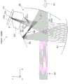
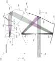
以下,参照图3等,更详细地说明上述各部的结构、图像光ML的光路引起的差异等。图3是用于说明构成虚像显示装置200的光学系统的各部的侧剖视图,在此,作为图像光ML中的中心光束的成分即中心成分CL之外的周边光束的成分,示出从光射出面10a中的接近配戴者US(眼睛EY)的一方射出的第1周边成分PLa和从远离配戴者US(眼睛EY)的一方射出的第2周边成分PLb。在图示中,用实线表示中心成分CL,用虚线表示周边成分中的第1周边成分PLa,用点划线表示第2周边成分PLb。图4是用于说明虚像显示装置200的光学系统的结构的概念性的图,第1区域BR1通过主视图示出光学系统的各部的配置,第2区域BR2通过俯视图示出光学系统的各部的配置。图5是示出虚像显示装置200的结构的立体图。另外,在图5中,以中心成分CL为代表而示出图像光ML。Hereinafter, with reference to FIG. 3 and the like, the configuration of each of the above-mentioned units, the difference due to the optical path of the image light ML, and the like will be described in more detail. 3 is a side cross-sectional view for explaining each part of the optical system constituting the virtual
如上所述,图3等所示的显示元件10是射出图像光ML的图像光生成部。显示元件(图像光生成部)10可以由各种元件构成,例如,显示元件10可以由自发光型的显示器件构成,在此情况下,为了产生图像光ML,显示元件10包括发光部。更具体而言,显示元件10例如由有机EL(有机电致发光,Organic Electro-Luminescence)显示器构成。在此,作为一例,显示元件10由有机EL显示器构成,从而将包含各种偏振方向的光(例如无偏振的光)作为图像光ML从光射出面10a射出,即在2维的光射出面10a形成彩色的静态图像或动态图像。但是,显示元件10不限于基于有机EL显示器的上述方式,可以置换为使用了微型LED显示器或无机EL、有机LED、激光器阵列、量子点发光型元件等的显示器件。进而,显示元件10不限于自发光型的图像光生成装置,也可以由LCD等光调制元件构成,通过由背光源那样的光源(发光部)照明该光调制元件而形成图像。作为显示元件10,也可以代替LCD而使用LCOS(Liquid crystal on silicon,LCoS为注册商标)、数字微镜器件等。As described above, the
棱镜20是在图像光ML的光路上配置在显示元件10和第1反射镜31之间、使从显示元件10射出的图像光ML折射并通过而入射到第1反射镜31的光折射光学元件(透镜)。如图3~图5所示,光学系统非轴对称地配置,具有非轴对称的光学面,成为离轴光学系统,该光学面包含自由曲面。因此,图像光ML根据相对于棱镜20的入射位置,在入射时或出射时,每个位置的折射的程度(折射角)不同。特别是,在本实施方式中,如图3所示,在棱镜20中的图像光ML所入射的入射部21,设置有第1入射区域21a和第2入射区域21b。第1入射区域21a是入射部21中的靠近佩戴者US(眼睛EY)的一侧即-Z侧的区域,第2入射区域21b是入射部21中的远离佩戴者US(眼睛EY)的一侧即+Z侧的区域。在此,如图所示,从第1入射区域21a到显示元件(图像光生成部)10的距离Da比从第2入射区域21b到显示元件10的距离Db长。即,图像光ML的周边成分中的虚线所示的第1周边成分PLa向入射部21入射的入射位置比点划线所示的第2周边成分PLb向入射部21入射的入射位置远。在此,关于从各入射区域21a、21b到显示元件10的距离,可进行各种定义,例如,能够以连结形成显示元件10的光射出侧的表面的光射出面10a上的1点和各入射区域21a、21b上的1点的直线的距离中的最小值或者最大值进行定义。The
另外,如图3中对棱镜20局部放大所示,图像光ML向入射部21入射的入射角在第1入射区域21a和第2入射区域21b中也不同,图像光ML向第1入射区域21a入射的入射角(第1周边成分PLa的入射角α)大于图像光ML向第2入射区域21b入射的入射角(第1周边成分PLa的入射角β)。即,α>β,入射到入射部21的图像光ML中的入射到第1入射区域21a的成分(第1周边成分PLa)比入射到第2入射区域21b的成分(第2周边成分PLb)更强地折射。In addition, as shown partially enlarged on the
进而,关于以上内容改变看法,在图示的一例中,从第1入射区域21a到第3反射镜33的距离比从第2入射区域21b到第3反射镜33的距离长。关于从各入射区域21a、21b到第3反射镜33的距离,可进行各种定义,例如能够以连结代表第3反射镜33的反射镜面上的1点和各入射区域21a、21b上的1点的距离中的最小值进行定义。Furthermore, to change the viewpoint of the above, in the illustrated example, the distance from the
另外,棱镜20具有从第1入射区域21a延伸而在-Z侧形成侧面的第1端部EGa和从第2入射区域21b延伸而在+Z侧形成侧面的第2端部EGb,作为侧面部分。在图示中,第1端部EGa比第2端部EGb薄。即,如图所示,从包括第1反射镜31、第2反射镜32和棱镜20的关于图像光ML的光束中心的假想剖面的法线方向看,在对沿图像光ML的光束中心的方向(光射出面10a的法线方向)上的第1端部EGa的厚度THa和第2端部EGb的厚度THb进行比较的情况下,厚度THa的值比厚度THb的值小。In addition, the
另外,在图示的情况下,从第1端部EGa到第3反射镜33的距离比从第2端部EGb到第3反射镜33的距离长。这里的距离也可以与上述的一例同样地定义。In addition, in the illustrated case, the distance from the first end portion EGa to the
进而,在棱镜20的射出从入射部21入射的图像光ML的射出部22中,设置有占据与第1端部EGa相连的一侧即-Z侧的第1射出区域22a、占据与第2端部EGb相连的一侧即+Z侧的第2射出区域22b。第1射出区域22a包含凹面,第2射出区域22b包含凸面。即,第1射出区域22a具有在沿着图像光ML的光束中心的方向(光射出面10a的法线方向)上朝内侧凹陷的面,第2射出区域22b具有在沿着图像光ML的光束中心的方向(光射出面10a的法线方向)上向外侧鼓起的面。Furthermore, in the
并且,在图示的情况下,从第1出射区域22a到第3反射镜33的距离比从第2出射区域22b到第3反射镜33的距离长。这里的距离也可以与上述的一例同样地定义。In addition, in the case of illustration, the distance from the
棱镜20通过具有以上的非对称形状,作为入射来自显示元件(图像光生成部)10的图像光ML并将其朝向第1反射镜31射出的光学部件,可避免或抑制第1反射镜31的大型化。即,在本实施方式的情况下,在虚像显示装置200的棱镜20中,构成为抑制图像光ML的周边成分伴随图像的广角化而扩大。By having the above asymmetric shape, the
如上所述,第1反射镜31配置在棱镜20的光射出侧,使从棱镜20射出的图像光ML反射(折返)。第1反射镜31利用反射镜反射,高效率地反射图像光ML,即100%或几乎100%地反射图像光ML。As described above, the first reflecting
在图3中,如对第1反射镜31局部放大示出的那样,第1反射镜31例如通过在树脂制的基材31a的表面利用反射镜蒸镀等形成反射膜(反射面)R1而构成。在基材31a中的设置有反射膜R1的面的相反侧的面上,为了防止漏光,例如也可以设置光吸收膜A1。在该情况下,光吸收膜A1也可以作为用于在反射膜R1的成膜时维持基材31a的形状(不使形状变化)的反向膜(counter film)发挥功能。或者,光吸收膜A1可考虑采用专门作为反向膜发挥功能的膜,不具有光吸收作用。通过设置反向膜,即使基材31a较薄(例如1mm左右)且作为形成基于自由曲面的反射面而具有某种程度的曲率,也能够以必要的精度维持反射面的形状。In FIG. 3 , as partially enlarged for the first reflecting
并且,如图3~图5所示,第1反射镜31与棱镜20的入射部(入射面)21、射出部(射出面)22、或者其它反射部件(第2反射镜32、第3反射镜33)同样,具有自由曲面。进而,第1反射镜31具有自由曲面,并且与棱镜20一起作为凸透镜发挥功能,由此,使图像光ML的光束整体会聚,并且朝向第2反射镜32。由此,实现第2反射镜32的小型化。And, as shown in FIGS. 3 to 5 , the incident portion (incident surface) 21 and the exit portion (exit surface) 22 of the
如上所述,第2反射镜32配置于第1反射镜31的光射出侧,使由第1反射镜31弯折(反射)的图像光ML进一步反射(折返),朝向第3反射镜33射出。在图示的一例的情况下,第2反射镜32设置于比第3反射镜33靠上方(+Y侧)的位置,图像光ML从第2反射镜32朝向第3反射镜33向斜下方投射。由此,第3反射镜33为半反射镜,即使图像光ML中的一部分的成分透过第3反射镜33,也能够避免或者减少该透射成分进入佩戴者以外的人的眼睛而看到图像的情况。As described above, the second reflecting
此外,第2反射镜32与第1反射镜31同样,具有自由曲面,并且通过反射镜反射,高效率地反射图像光ML,即100%或几乎100%地反射图像光ML。关于结构,也与第1反射镜31同样,例如可考虑在树脂制的基材31a的表面通过反射镜蒸镀等形成反射膜,进而设置光吸收膜等(省略图示)。Also, the
如上所述,第3反射镜33是具有半透射性的半反射镜,配置于第2反射镜32的光射出侧。经过了第2反射镜32的图像光ML的一部分被第3反射镜33反射。在此,第3反射镜33反射后的图像光ML朝向成为眼睛EY的假想位置(出射光瞳的位置)的出射光瞳PP。例如,与图像光ML中的中心成分CL有关的第3反射镜33中的反射成分朝向-Z方向,到达出射光瞳PP。作为中心成分CL以外的反射成分的第1周边成分PLa和第2周边成分PLb也同样到达出射光瞳PP。另外,出射光瞳PP成为来自光射出面10a上的各点的图像光ML以规定的发散状态从与光射出面10a上的各点的位置对应的角度方向重叠地入射的位置。在第3反射镜33中,由具有半透射性的膜形成透射反射面R3。As described above, the third reflecting
另外,关于作为半反射镜的第3反射镜33的反射透射率,可考虑各种设定,例如可考虑以反射率约50%、透射率约50%的方式形成半反射膜等。在本实施方式的情况下,关于第3反射镜33以外的第1反射镜31以及第2反射镜32,采用高效率反射的反射镜,第3反射镜33中的图像光ML的通过也仅为1次,所以,与例如多次经过半反射镜等的Birdbath型的光学系统相比,能够较高地维持作为光学系统整体的图像光ML的利用效率。Various settings can be considered for the reflective transmittance of the third
在此,如图3等所示,第1反射镜31的反射膜R1配置于眼睛EY的附近且朝上,即配置为向+Y方向反射光。因此,例如,与图2对应的图6所示的那样,来自外界的光中的太阳光等成分如果被第1反射镜31反射,则朝向眼睛EY而向对观察带来不良影响的非期望方向反射的光SL成为问题。与此相对,在本实施方式中,在第1反射镜31(反射膜R1)上设置角度依赖性以使光SL不反射,如图所示,能够避免或抑制光SL朝向眼睛EY的情况。Here, as shown in FIG. 3 and the like, the reflection film R1 of the
图7是用于说明构成本实施方式的虚像显示装置200的第1反射镜31或第1反射镜31的反射面(反射膜)R1的角度依赖性的曲线图。曲线图的横轴表示第1反射镜31的光的入射角度(单位:°),纵轴表示与光的入射角度相对的第1反射镜31的反射率(单位:%)。如曲线(或折线)Q1所示,第1反射镜31(反射膜R1)具有这样的特征作为角度依赖性:对于以入射角度为45°以下的角度入射的光呈现高反射性(反射率),另一方面,对于以大于45°的角度入射的光呈现非常低的反射性(反射率)。即,在第1反射镜31(反射膜R1)中,以45°以下的角度入射的光的反射率比以大于45°的角度入射的光的反射率高。关于具有上述角度依赖性的反射膜R1的成形,例如可考虑由电介质多层膜构成。FIG. 7 is a graph for explaining the angular dependence of the first reflecting
在图3等所示的第1反射镜31的情况下,入射到第1反射镜31的图像光ML的入射角度都比较小,即使在图像光ML形成大到某种程度的视场角的图像的情况下,也可认为图像光ML相对于第1反射镜31的最大入射角度为30°左右。因此,在第1反射镜31中,如果至少在30°左右的范围内更优选在45°左右的范围内维持较高的反射性,则可认为足以确保图像光ML的反射。In the case of the
另一方面,图6所示的光SL那样的光即通过被第1反射镜31(反射膜R1)反射而朝向眼睛EY的成分可设想为相对于第1反射镜31以大到某种程度以上的角度入射的光。因此,第1反射镜31具有上述的角度依赖性,由此,能够适当地避免或抑制光SL朝向眼睛EY的情况。On the other hand, light such as light SL shown in FIG. 6, that is, the component that is reflected by the first reflecting mirror 31 (reflecting film R1) and goes toward the eye EY is assumed to be larger than the first reflecting
另外,第3反射镜33也可以具有上述的角度依赖性。例如,第3反射镜33也可以在对图像光ML或外界光OL进行透射或反射的透射反射面R3中具有角度依赖性,在透射反射面R3中,以大于45°的角度入射的光的反射率高于以45°以下的角度入射的光的反射率。入射到第3反射镜33的图像光ML的入射角度也都比较小,即使在图像光ML形成大到某种程度的视场角的图像的情况下,也可认为图像光ML相对于第1反射镜31的最大入射角度为30°左右。In addition, the third reflecting
如上所述,本实施方式的虚像显示装置200具备:显示元件10,其是生成图像光ML的图像光生成部;第1反射镜31,其反射图像光ML;第2反射镜32,其反射由第1反射镜31反射后的图像光ML;以及第3反射镜33,其使外界光OL透过并且使由第2反射镜32反射后的图像光ML的一部分向出射光瞳PP的位置反射,第1反射镜31具有反射率根据图像光ML入射的角度而不同的角度依赖性。在虚像显示装置200中,在第3反射镜33中,使外界光OL透过,并且使由第2反射镜32反射的图像光ML的一部分向出射光瞳PP的位置反射,从而能够进行所谓的透视的观察,同时第1反射镜31具有反射率根据图像光ML入射的角度而不同的角度依赖性,从而对于图像光ML维持可靠的反射,并且能够避免或抑制由来自外界的非期望成分(图6的光SL等)的反射引起的重影光等的产生。As described above, the virtual
并且,在上述方式的情况下,在棱镜20中,通过使从第1入射区域21a与第2入射区域21b中的第1入射区域21a到显示元件10的距离比从第2入射区域21b到显示元件10的距离长,能够避免或抑制设置于棱镜20的光路后级的作为反射面的多个反射镜(第1反射镜31等)的大型化,尤其是第1反射镜31的大型化乃至装置整体的大型化。And, in the case of the above-mentioned mode, in the
进而,在上述方式的情况下,通过采用自由曲面作为各光学系统中的折射面和反射面,在广角化时,将各光学系统维持为小型化,并且抑制图像畸变(畸变像差)的发生。另外,也能够良好地维持分辨率。Furthermore, in the case of the above-mentioned form, by adopting the free-form surface as the refraction surface and the reflection surface in each optical system, when widening the angle of view, each optical system is kept downsized and the occurrence of image distortion (distortion aberration) is suppressed. . In addition, resolution can also be maintained well.
以下,参照图8说明一变形例的虚像显示装置200。在本变形例中,第3反射镜33是反射特定的偏振状态的光的偏振反射镜。而且,虚像显示装置200还具有使图像光ML成为与第3反射镜33的偏振特性相应的偏振状态的偏振板PA。在图8中,作为一例,示出偏振板PA设置在图像光ML的光路中的棱镜20与第1反射镜31之间的光路上、且设置在不与第3反射镜33向出射光瞳PP的位置反射的图像光ML交叉的位置的情况。在该情况下,图像光ML通过由偏振板PA进行偏振,成为与第3反射镜33的反射特性对应的特定的偏振状态(例如,在向作为与P偏振光相比对于S偏振光呈现较高反射特性的偏振反射镜的第3反射镜33入射时成为S偏振光)。由此,在第3反射镜33中,高效率地反射图像光ML。在上述内容中,偏振板PA设置于图像光ML的光路上的棱镜20与第1反射镜31之间的光路上,但也可以考虑例如在从作为图像光生成部的显示元件10到棱镜20的光路上设置偏振板PA的方式。通过设置偏振板PA,能够提高图像光ML的利用效率。Hereinafter, a modified virtual
并且,相对于上述方式的第3反射镜33,作为图像光生成部的显示元件10也可以以与作为偏振镜的第3反射镜33的偏振特性对应的偏振状态射出图像光ML。例如,可以考虑采用通过作为背光灯的光源(发光部)对LCD进行照明而形成图像的元件作为显示元件10,从而使图像光ML以相对于第3反射镜33成为S偏振光的状态射出。在这种情况下,可以采用不设置图8所示的偏振板PA的结构。Furthermore, the
[第2实施方式][the second embodiment]
以下,参照图9等说明第2实施方式的虚像显示装置。作为本实施方式的虚像显示装置的一例的虚像显示装置,对第1实施方式的虚像显示装置200进行部分变更,除了引导图像光ML的光学系统的结构之外的其它结构与第1实施方式的情况相同,所以,关于整体结构等,省略详细的图示、说明,根据需要而适当引用参照其它附图说明的事项。Hereinafter, a virtual image display device according to a second embodiment will be described with reference to FIG. 9 and the like. The virtual image display device as an example of the virtual image display device according to the present embodiment partially changes the virtual
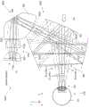
图9是示出本实施方式的虚像显示装置400中的图像光ML的光路的概念性的侧剖视图,是与图2对应的图。另外,图10是用于说明构成虚像显示装置400的光学系统的各部的侧剖视图,是与图3的一部分等对应的图。另外,图11是示出虚像显示装置400的结构的立体图,是与图5对应的图。另外,在图11中,仅示出后述的棱镜部件PZ中的图像光ML折射或反射的部位。FIG. 9 is a conceptual side sectional view showing the optical path of the image light ML in the virtual
如图9~图11所示,构成本实施方式的虚像显示装置400的右眼用的第1显示装置300A以及左眼用的第2显示装置300B与图1等所示的右眼用的第1显示装置100A以及左眼用的第2显示装置100B同样地左右成对构成,所以,示出一方的第1显示装置300A。另外,虚像显示装置400的整体外观及结构与图1的虚像显示装置200相同。As shown in FIGS. 9 to 11 , the
如图9等所示,作为具有光学功能的部分,第1显示装置300A具备:显示元件10,其是射出图像光ML的图像光生成部;光学部件320,其入射来自显示元件10的图像光ML;以及反射光学元件330,其由对来自光学部件320的图像光ML进行反射的3个反射部件(第1反射镜331、第2反射镜332、第3反射镜333)构成。反射光学元件330中的第2反射镜332与第1实施方式中的第2反射镜32同样具有关于光反射的角度依赖性。第3反射镜333也与第1实施方式中的第3反射镜33同样地可以采用具有角度依赖性的结构。As shown in FIG. 9 and the like, as a part having an optical function, the
光学部件320是设置于从作为图像光生成部的显示元件10到第1反射镜331的光路上并将来自显示元件10的图像光ML朝向第1反射镜331射出的部件。在图示的一例中,光学部件320由投影透镜PO和棱镜部件PZ构成。在光学部件320中,将棱镜部件PZ作为第1光学部件,将投影透镜PO作为第2光学部件。The
投影透镜(第2光学部件)PO由第1透镜PO1和第2透镜PO2构成,将从显示元件10射出的图像光ML朝向棱镜部件PZ中的后述的入射部PZ1射出。The projection lens (second optical member) PO is composed of a first lens PO1 and a second lens PO2, and emits the image light ML emitted from the
另一方面,棱镜部件PZ(第1光学部件)具有图像光ML入射的入射部PZ1、反射从入射部PZ1入射的图像光ML的反射部RR、和将由反射部RR反射的图像光ML朝向第1反射镜331射出的射出部PZ2。On the other hand, the prism part PZ (first optical part) has an incident part PZ1 where the image light ML is incident, a reflection part RR that reflects the image light ML incident from the incident part PZ1, and a reflector RR that reflects the image light ML reflected by the reflection part RR toward the first 1 The emission part PZ2 from which the
在上述结构的第1显示装置300A中,首先,从显示元件10的光射出面10a射出的图像光ML从投射透镜PO向棱镜部件PZ射出,入射到入射部PZ1而折射。从入射部PZ1入射到棱镜部件PZ的内部的图像光ML被反射部RR反射(内面反射),朝向射出部PZ2,从射出部PZ2折射而射出,从而向在下方向(-Y方向)具有成分的方向投射。经过了棱镜部件PZ的图像光ML首先被位于棱镜部件PZ的下方而构成反射光学元件330的作为3个反射部件的第1反射镜331、第2反射镜332、第3反射镜333中的位于最下方的第1反射镜331反射,朝向位于在上方向(+Y方向)具有成分的方向的第2反射镜332。也就是说,第1反射镜331在安装时位于比包括棱镜部件PZ等的光学部件320及第2反射镜332靠下方的位置,将从光学部件320朝下方投射的图像光ML向上方反射。In the
经过了第1反射镜331的图像光ML由第2反射镜332反射,再次朝向下方,这次入射到第3反射镜333。第3反射镜333使来自第2反射镜332的图像光ML成为平行光束,并且朝向成为佩戴者US的眼睛EY的位置的出射光瞳PP弯折。The image light ML passing through the
并且,以上的情况也与图2等所示的第1显示装置100A的情况同样,从棱镜部件PZ到第1反射镜331的图像光ML的光路与从第2反射镜332到第3反射镜333的图像光ML的光路交叉,并且与从第3反射镜333朝向出射光瞳PP的位置的图像光ML的光路交叉。即,在反射光学元件330中,图像光ML的光路多次交叉地弯折,从而具有某种程度的光路长度,并且光学系统整体实现小型化。In addition, the above case is the same as that of the
并且,作为光学的其它方面,光学部件320及第1反射镜331一并作为凸透镜发挥作用。并且,在图示的一例中,在第1反射镜331与第2反射镜332之间形成中间像IM。In addition, as another aspect of optics, the
另外,在第3反射镜333作为具有半透射性的半反射镜发挥作用从而构成透视型的光学系统的方面也相同。The same applies to the point that the
以下,参照图12对构成第1显示装置300A的上述光学系统的原理进行说明。图12是概念性地示出将构成第1显示装置300A的光学系统展开的状况的图。在图示中,虚线表示的光线LL1表示从1个点光源射出的周边光的情况,在图中,光线LL1交叉的点表示中间像IM的位置等成像位置。另一方面,实线表示的光线LL2表示从不同的点光源射出的主光线的情况,在图中,光线LL2交叉的点表示光瞳的位置。例如,在设置光圈的情况下,优选在该点或该点附近。并且,往返箭头表示的第1透镜组LS1相当于光学部件320即投影透镜PO及棱镜部件PZ,第2透镜组LS2相当于第1反射镜331,第3透镜组LS3相当于第2反射镜332及第3反射镜333。第4个往返箭头相当于作为透镜发挥作用的人的眼睛EY(晶状体)。Hereinafter, the principle of the optical system constituting the
在此,在图示中,第1透镜组LS1的焦距为L,与此相对,第2透镜组LS2及第3透镜组LS3的焦距分别为2L(即L的2倍),即第1透镜组LS1的屈光力较强,第2透镜组LS2或第3透镜组LS3的屈光力较弱。换言之,在第1透镜组LS1侧即投影侧,增大屈光力的负荷,另一方面,在第2透镜组LS2或第3透镜组LS3即与眼睛EY(出射光瞳PP的位置)接近的一侧,减小屈光力,成为需要距离的光学系统。由此,成为由3个反射镜(第1反射镜331、第2反射镜332、第3反射镜333)争取距离,并抑制畸变(失真)的结构。在本结构的情况下,虽然光学系统自身为偏心系统,但容易进行畸变校正,所以,仅通过旋转对称系统的结构就能够构成良好地进行了校正的光学系统。即,第1反射镜331、第2反射镜332、第3反射镜333、棱镜部件PZ及投影透镜PO可以为旋转对称光学系统。关于上述结构,也可以理解为在屈光力较强的第1透镜组LS1(投影透镜PO、棱镜部件PZ)中,通过使用多个透镜进行校正实现上述结构。即,在图示的一例的情况下,投影透镜PO由2个折射光学系统(图9等所示的透镜PO1、PO2)构成,棱镜部件PZ由2个折射入射面和1个反射面构成。Here, in the figure, the focal length of the first lens group LS1 is L, while the focal lengths of the second lens group LS2 and the third lens group LS3 are respectively 2L (that is, twice of L), that is, the first lens group The refractive power of the group LS1 is strong, and the refractive power of the second lens group LS2 or the third lens group LS3 is weak. In other words, on the side of the first lens group LS1, that is, on the projection side, the load on the refractive power increases, while on the other hand, on the side of the second lens group LS2 or the third lens group LS3, that is, the side closer to the eye EY (the position of the exit pupil PP). side, reduce the refractive power, and become an optical system that requires a distance. Thereby, the three reflecting mirrors (the first reflecting
以下,参照图13说明光圈(遮光部、孔)ST的一个结构例。在图中,第1区域DR1概念性地示出板状的光圈ST,例如,如图所示,也可以通过在圆盘状的板部件BA的中央部分设置与图像光ML的轮廓形状对应的形状(例如矩形状)的开口OP而形成光圈ST。如参照图12说明的那样,在图12所示的情况下,光圈ST优选设置于光线LL2交叉的点。即,优选配置在从投影透镜PO到棱镜部件PZ的位置。因此,作为另一例,也可以如第2区域DR2所示,通过对表示为状态α1的棱镜部件PZ中的入射部PZ1或射出部PZ2的周围,如状态β2所示那样进行涂黑(遮光掩模),从而作为光圈ST发挥作用。特别是,通过至少在射出部PZ2的周围设置光圈ST,能够期待有效的遮光。即,射出部PZ2可以构成为具有对由反射部RR反射的图像光ML中的一部分进行遮光的光圈(遮光部)ST。另外,在上述方式中,针对反射部RR,也可以对反射所需的部位的周围进行涂黑。Hereinafter, an example of the configuration of the diaphragm (shading portion, hole) ST will be described with reference to FIG. 13 . In the figure, the first region DR1 conceptually shows a plate-shaped diaphragm ST. For example, as shown in the figure, it is also possible to provide a diaphragm corresponding to the contour shape of the image light ML in the central part of the disc-shaped plate member BA. A shape (for example, a rectangular shape) of the opening OP forms a stop ST. As described with reference to FIG. 12 , in the case shown in FIG. 12 , it is preferable to install the diaphragm ST at a point where the light rays LL2 intersect. That is, it is preferably arranged at a position from the projection lens PO to the prism member PZ. Therefore, as another example, as shown in the second region DR2, the surroundings of the incident part PZ1 or the emitting part PZ2 in the prism part PZ shown in the state α1 may be painted black as shown in the state β2 (light-shielding mask mode), thus functioning as the aperture ST. In particular, effective light shielding can be expected by providing the diaphragm ST at least around the exit portion PZ2. That is, the emission unit PZ2 may be configured to have a stop (light shielding unit) ST that shields part of the image light ML reflected by the reflection unit RR. In addition, in the above-mentioned form, you may black-paint the periphery of the part required for reflection with respect to the reflection part RR.
以下,参照图14说明一变形例的虚像显示装置400。另外,图14是与图8对应的图。即,在本变形例中,例示了在虚像显示装置400内设置偏振板PA的情况,在图14中,关于偏振板PA的配置部位,用虚线示出成为候补的部位。即,作为偏振板PA的可配置部位的例示,可考虑显示元件10的最接近的后级、投影透镜PO即第1透镜PO1与第2透镜PO2之间、棱镜部件PZ的前级(入射部PZ1的位置)或后级(射出部PZ2的位置)等。即,能够将偏振板PA配置在从作为图像光生成部的显示元件10到第1反射镜331为止的光路上的各种位置。通过在这些位置中的任一位置设置偏振板PA,能够与参照图8说明的情况同样地提高图像光ML的利用效率。Hereinafter, a modified virtual
以下,参照图15说明另一变形例的虚像显示装置400。如参照图12说明的那样,在本实施方式中,能够将光学系统设为旋转对称系统且畸变少的系统。在该情况下,对于光学系统的一部分,即使在光线行进方向(光轴方向)上稍微移动,也可认为影像整体均等地变化。因此,这里采用利用该性质进行影像焦距的调整的方式。具体而言,如第1区域ER1所示的一例那样,关于投影透镜PO中的被虚线PP1包围而示出的第2透镜PO2,能够沿点划线所示的光轴AX在箭头AA1所示的方向(负方向)上移动(能够调整)。第2区域ER2所示的曲线图描绘了使第2透镜PO2向显示元件10侧移动时的调整量(第2透镜PO2的移动量)与影像焦距的关系。即,在图示的曲线图中,横轴表示调整量即第2透镜PO2向箭头AA1所示的方向移动的值(负值),纵轴表示影像焦距即到识别为存在与调整量对应的作为虚像的图像的位置的距离。在该情况下,如果具有约0.5mm的调整幅度,则能够在接近2500mm的范围内进行影像焦距的调整。如上所述,投影透镜PO通过构成为包括能够在光线行进方向上移动的透镜(第2透镜PO2),能够调整影像焦距。Hereinafter, a virtual
在本实施方式中,第1反射镜331具有角度依赖性,由此,也能对图像光ML维持可靠的反射,并且能够避免或抑制因来自外界的不希望的成分的反射而产生重影光等。另外,在本实施方式中,能够由旋转对称的光学系统构成。In the present embodiment, the
[第3实施方式][the third embodiment]
以下,参照图16等说明作为第3实施方式的虚像显示装置的虚像显示装置。作为本实施方式的虚像显示装置的一例的虚像显示装置,对第1实施方式的虚像显示装置200等的一部分进行了变更,除了第1反射镜31和第3反射镜33一体化之外的其它结构与第1实施方式等的情况相同,所以,关于整体结构等,省略详细的图示和说明,根据需要而适当引用参照其它附图说明的事项。Hereinafter, a virtual image display device as a virtual image display device according to a third embodiment will be described with reference to FIG. 16 and the like. The virtual image display device as an example of the virtual image display device of the present embodiment is a part of the virtual
图16是示出本实施方式的虚像显示装置200的概略的侧剖视图,是对应于图2的图。即,在图16中,代表性地示出从显示元件10射出的图像光ML中的中心光束(中心成分CL)。在此情况下,通过使第1反射镜31和第3反射镜33一体化,可容易维持组装精度,并且能够减少光学部件的数量。另外,能够抑制尘埃等从第1反射镜31与第3反射镜33的间隙进入。FIG. 16 is a schematic side sectional view showing a virtual
关于第1反射镜31与第3反射镜33的连接部CN,通过设置为图像光ML不通过的部分,能够在图像光ML的导光时不产生影响。The connecting portion CN between the first reflecting
另外,图17是示出本实施方式的一变形例的虚像显示装置400的概略的侧剖视图,是对应于图9的图。即,在图17中,通过使第1反射镜331与第3反射镜333一体化,容易维持组装精度,并且能够减少光学部件的数量。并且,能够抑制尘埃等从第1反射镜331与第3反射镜333的间隙进入。In addition, FIG. 17 is a schematic side sectional view showing a virtual
在本实施方式中,也能够对图像光ML维持可靠的反射,并且避免或抑制由来自外界的不希望的成分的反射引起的重影光等的产生。另外,在本实施方式中,能够实现组装精度的维持的简化等。Also in this embodiment, while maintaining reliable reflection of the image light ML, it is possible to avoid or suppress generation of ghost light or the like due to reflection of unwanted components from the outside. In addition, in the present embodiment, simplification of maintenance of assembly accuracy and the like can be achieved.
[变形例及其它][Modifications and others]
以上按照各实施方式说明了本发明,但本发明不限于上述的实施方式,在不脱离其主旨的范围内能够以各种方式实施,例如也能够进行如下的变形。As mentioned above, although this invention was demonstrated based on each embodiment, this invention is not limited to said embodiment, It can implement in various forms in the range which does not deviate from the summary, For example, the following deformation|transformation is also possible.
首先,在上述内容中,例示了在光路上的一处设置中间像的结构,但不限于此,也可以构成在多处(2处)形成中间像的系统。First, in the above description, the structure in which an intermediate image is provided at one place on the optical path was exemplified, but the present invention is not limited to this, and a system in which intermediate images are formed at multiple places (two places) may also be configured.
另外,在上述内容中,关于壳体CS,在不损害上述光学功能的范围内可采用各种方式,例如,如上所述,可以采用这样的结构:除了设置用于将各光学系统固定在规定位置的安装用部件以外,还具有防尘功能。In addition, in the above, regarding the casing CS, various methods can be adopted within the scope not to impair the above-mentioned optical functions. In addition to the parts for installation in the position, it also has a dustproof function.
在上述内容中,采用了双眼用的虚像显示装置200,但是关于虚像显示装置200,能够省略右眼用或左眼用的部分中的一方。也就是说,也能够仅由右眼用的第1显示装置100A或左眼用的第2显示装置100B形成虚像显示装置200的光学系统,在该情况下,成为单眼型的头戴式显示器。In the above description, the virtual
具体方式中的虚像显示装置具有:图像光生成部,其生成图像光;第1反射镜,其使图像光反射;第2反射镜,其使由第1反射镜反射的图像光反射;以及第3反射镜,其使外界光透过,并且使由第2反射镜反射的图像光的一部分向出射光瞳的位置反射,第1反射镜具有反射率根据图像光入射的角度而不同的角度依赖性。A virtual image display device in a specific form includes: an image light generating unit that generates image light; a first reflector that reflects the image light; a second reflector that reflects the image light reflected by the first reflector; and a second reflector. 3 mirrors that transmit external light and reflect a part of the image light reflected by the second mirror toward the position of the exit pupil. sex.
在上述虚像显示装置中,在第3反射镜中,使外界光透过,并且使由第2反射镜反射后的图像光的一部分向出射光瞳的位置反射,从而能够进行所谓的透视的观察,同时,第1反射镜具有反射率根据图像光入射的角度而不同的角度依赖性,从而对于图像光维持可靠的反射,并且能够避免或抑制由来自外界的不希望的成分的反射引起的重影光等的产生。In the above-mentioned virtual image display device, external light is transmitted through the third mirror, and part of the image light reflected by the second mirror is reflected toward the position of the exit pupil, so that so-called see-through observation can be performed. , and at the same time, the first reflector has a reflectivity that varies depending on the angle at which the image light is incident, thereby maintaining reliable reflection for the image light, and avoiding or suppressing the occurrence of refraction caused by reflection of unwanted components from the outside. The production of shadows and light, etc.
在具体的方面中,在第1反射镜中,以45°以下的角度入射的图像光的反射率比以大于45°的角度入射的图像光的反射率高。在该情况下,即使图像光成为广视场角的光,也能够维持高的反射性,并且避免或抑制不期望的光朝向佩戴者。In a specific aspect, in the first reflecting mirror, the reflectance of image light incident at an angle of 45° or less is higher than the reflectance of image light incident at an angle greater than 45°. In this case, even if the image light becomes light with a wide viewing angle, high reflectivity can be maintained, and unwanted light can be prevented or suppressed from being directed toward the wearer.
在具体的方面中,第3反射镜使图像光的一部分以通过第1反射镜和第2反射镜之间的方式反射。此时,可实现光学系统的紧凑化。In a specific aspect, the third mirror reflects a part of the image light so as to pass between the first mirror and the second mirror. In this case, the compactness of the optical system can be realized.
在具体的方面中,第1反射镜与图像光生成部相比相对于出射光瞳的位置位于下方,第1反射镜向相对于出射光瞳的位置位于上方的第2反射镜图像光。在该情况下,能够将光源配置于在佩戴时不易妨碍佩戴者的位置,并且使光路弯折,确保光学系统的光路,并且使光学系统成为紧凑的结构。In a specific aspect, the first mirror is positioned below the exit pupil relative to the image light generating unit, and the first mirror directs image light to the second mirror positioned above the exit pupil. In this case, the light source can be arranged at a position where the wearer does not easily obstruct the wearer, and the optical path can be bent to secure the optical path of the optical system and make the optical system compact.
在具体的方面中,第3反射镜具有对于以大于45°的角度入射的光的反射率比对于以45°以下的角度入射的光的反射率高的角度依赖性的反射率。在该情况下,能够避免或者抑制不期望的光朝向佩戴者。In a specific aspect, the third reflecting mirror has an angle-dependent reflectance that is higher for light incident at an angle greater than 45° than for light incident at an angle of 45° or less. In this case, undesired light directed toward the wearer can be avoided or suppressed.
在具体的方面中,第3反射镜是反射特定的偏振状态的图像光的偏振反射镜。在该情况下,能够高效率地利用图像光。In a specific aspect, the third mirror is a polarizing mirror that reflects image light in a specific polarization state. In this case, image light can be efficiently used.
在具体的方面中,图像光生成部射出偏振状态的图像光。在此情况下,通过图像光生成部与第3反射镜协作,能够高效率地利用图像光。In a specific aspect, the image light generation unit emits image light in a polarized state. In this case, the image light generation unit cooperates with the third mirror to efficiently use the image light.
在具体的方面中,虚像显示装置具有偏振板,偏振板设置在从图像光生成部到第1反射镜的光路上,使从图像光生成部射出的图像光成为偏振状态。在该情况下,通过偏振板与第3反射镜进行协作,能够高效地利用图像光。In a specific aspect, the virtual image display device includes a polarizing plate disposed on an optical path from the image light generating unit to the first reflection mirror to make the image light emitted from the image light generating unit into a polarized state. In this case, image light can be efficiently used by cooperation of the polarizing plate and the third mirror.
在具体的方面中,虚像显示装置具备光学部件,光学部件设置在从图像光生成部到第1反射镜的光路上,将来自图像光生成部的图像光朝向第1反射镜射出。In a specific aspect, the virtual image display device includes an optical member provided on an optical path from the image light generation unit to the first reflection mirror, and emits the image light from the image light generation unit toward the first reflection mirror.
在具体的方面中,光学部件包括向第1反射镜进行射出的第1光学部件,第1光学部件具有供图像光入射的入射部、反射从入射部入射的图像光的反射部、以及将由反射部反射的图像光朝向第1反射镜射出的射出部。在该情况下,能够使位于光源侧的光学部件成为光学系统整体中的屈光力强的结构。In a specific aspect, the optical component includes a first optical component that emits to the first reflecting mirror, the first optical component has an incident portion through which the image light is incident, a reflective portion that reflects the image light incident from the incident portion, and The image light reflected by the part is directed toward the output part from which the first reflecting mirror is output. In this case, the optical member located on the light source side can be configured to have a strong refractive power in the entire optical system.
在具体的方面中,第1光学部件在射出部具有对由反射部反射的图像光的一部分进行遮光的光圈。此时,在光瞳(入射光瞳)的位置或其附近能够进行遮光。In a specific aspect, the first optical member has a diaphragm that blocks part of the image light reflected by the reflection part in the exit part. At this time, light can be shielded at the position of the pupil (entrance pupil) or its vicinity.
在具体的方面中,光学部件包括第2光学部件,第2光学部件将从图像光生成部射出的图像光朝向第1光学部件的入射部射出。在该情况下,在第2光学部件中,能够成为光学系统整体中的屈光力较强的结构。In a specific aspect, the optical component includes a second optical component that emits the image light emitted from the image light generation unit toward the incident portion of the first optical component. In this case, the second optical member can have a relatively strong refractive power in the entire optical system.
在具体的方面中,第1反射镜、第2反射镜、第3反射镜、第1光学部件以及第2光学部件是旋转对称光学系统。此时,能够容易地制作各光学系统。In a specific aspect, the first mirror, the second mirror, the third mirror, the first optical component, and the second optical component are rotationally symmetric optical systems. In this case, each optical system can be easily produced.
在具体的方面中,第2光学部件能够在图像光生成部与第1光学部件之间的光路上移动。在这种情况下,能够调整影像焦距。In a specific aspect, the second optical member is movable on the optical path between the image light generating unit and the first optical member. In this case, the image focus can be adjusted.
在具体的方面中,光学部件以与第2反射镜朝向第3反射镜反射的图像光的光路以及第3反射镜朝向出射光瞳的位置反射的图像光的光路交叉的方式朝向第1反射镜投射图像光。在该情况下,能够多次弯折图像光的光路,确保光学系统的光路,并且使光学系统更小型。In a specific aspect, the optical member faces the first reflecting mirror so as to cross the optical path of the image light reflected by the second reflecting mirror toward the third reflecting mirror and the optical path of the image light reflected by the third reflecting mirror toward the exit pupil. Casts an image light. In this case, the optical path of the image light can be bent multiple times, the optical path of the optical system can be ensured, and the optical system can be made smaller.
在具体的方面中,第1反射镜和第3反射镜一体化。在该情况下,能够实现组装精度的维持的简化等。In a specific aspect, the first reflecting mirror and the third reflecting mirror are integrated. In this case, simplification of maintenance of assembly accuracy and the like can be achieved.
Claims (16)
Translated fromChineseApplications Claiming Priority (2)
| Application Number | Priority Date | Filing Date | Title |
|---|---|---|---|
| JP2021125111AJP2023020005A (en) | 2021-07-30 | 2021-07-30 | virtual image display |
| JP2021-125111 | 2021-07-30 |
Publications (1)
| Publication Number | Publication Date |
|---|---|
| CN115685550Atrue CN115685550A (en) | 2023-02-03 |
Family
ID=85037883
Family Applications (1)
| Application Number | Title | Priority Date | Filing Date |
|---|---|---|---|
| CN202210889692.4AWithdrawnCN115685550A (en) | 2021-07-30 | 2022-07-27 | virtual image display device |
Country Status (3)
| Country | Link |
|---|---|
| US (1) | US12345890B2 (en) |
| JP (1) | JP2023020005A (en) |
| CN (1) | CN115685550A (en) |
Citations (3)
| Publication number | Priority date | Publication date | Assignee | Title |
|---|---|---|---|---|
| US20030063400A1 (en)* | 2001-06-26 | 2003-04-03 | Toshihiro Sunaga | Reflective optical element, reflective optical system, image display system, and finder optical system |
| CN110780444A (en)* | 2018-07-30 | 2020-02-11 | 精工爱普生株式会社 | Virtual image display device |
| CN112444991A (en)* | 2019-08-28 | 2021-03-05 | 精工爱普生株式会社 | Virtual image display device and light guide device |
Family Cites Families (1)
| Publication number | Priority date | Publication date | Assignee | Title |
|---|---|---|---|---|
| JP2003005074A (en) | 2001-06-26 | 2003-01-08 | Canon Inc | Reflection optical system, reflection type optical system and optical apparatus |
- 2021
- 2021-07-30JPJP2021125111Apatent/JP2023020005A/enactivePending
- 2022
- 2022-07-27CNCN202210889692.4Apatent/CN115685550A/ennot_activeWithdrawn
- 2022-07-29USUS17/876,762patent/US12345890B2/enactiveActive
Patent Citations (3)
| Publication number | Priority date | Publication date | Assignee | Title |
|---|---|---|---|---|
| US20030063400A1 (en)* | 2001-06-26 | 2003-04-03 | Toshihiro Sunaga | Reflective optical element, reflective optical system, image display system, and finder optical system |
| CN110780444A (en)* | 2018-07-30 | 2020-02-11 | 精工爱普生株式会社 | Virtual image display device |
| CN112444991A (en)* | 2019-08-28 | 2021-03-05 | 精工爱普生株式会社 | Virtual image display device and light guide device |
Also Published As
| Publication number | Publication date |
|---|---|
| US20230030353A1 (en) | 2023-02-02 |
| US12345890B2 (en) | 2025-07-01 |
| JP2023020005A (en) | 2023-02-09 |
Similar Documents
| Publication | Publication Date | Title |
|---|---|---|
| US11275246B2 (en) | Head-mounted display | |
| CN112444991B (en) | Virtual image display device and light guide device | |
| US20190369399A1 (en) | Head-mounted display device | |
| CN112444992B (en) | Virtual image display device and light guide device | |
| WO2016181459A1 (en) | Prism optical system, image display device using prism optical system, and imaging device using prism optical system | |
| US10302949B2 (en) | Virtual image display apparatus including a diffraction optical member having a diffraction section and a light transmissive substrate | |
| CN109073896B (en) | Spectacle lens for imaging optical unit and data goggles | |
| US11327309B2 (en) | Virtual image display apparatus | |
| CN114545628B (en) | Display module, virtual image display device, and method for manufacturing light guide optical device | |
| US11506894B2 (en) | Display device | |
| CN114578550B (en) | Display modules and display devices | |
| CN111142249A (en) | display device | |
| CN115685550A (en) | virtual image display device | |
| US12345889B2 (en) | Virtual image display device | |
| JP5781165B2 (en) | Head-mounted image display device | |
| US12292574B2 (en) | Optical module, virtual image display device, and light-guiding device | |
| CN114428401B (en) | Display module, method for assembling display module, and virtual image display device | |
| US12313849B2 (en) | Virtual image display device and optical unit | |
| US20250004278A1 (en) | Virtual image display device and optical unit | |
| US20240219722A1 (en) | Virtual image display device and optical unit | |
| JP2001343607A (en) | Method for manufacturing light guide element in image display device, image display device, and image display system | |
| JP2025006919A (en) | Virtual image display device and optical unit | |
| JP2024077798A (en) | Optical system and display device | |
| JP2025030211A (en) | Virtual image display device and optical unit | |
| JP2025090917A (en) | Optical system and display device |
Legal Events
| Date | Code | Title | Description |
|---|---|---|---|
| PB01 | Publication | ||
| PB01 | Publication | ||
| SE01 | Entry into force of request for substantive examination | ||
| SE01 | Entry into force of request for substantive examination | ||
| WW01 | Invention patent application withdrawn after publication | Application publication date:20230203 |