CN115684690A - An energy harvesting and current measuring device - Google Patents
An energy harvesting and current measuring deviceDownload PDFInfo
- Publication number
- CN115684690A CN115684690ACN202211423591.4ACN202211423591ACN115684690ACN 115684690 ACN115684690 ACN 115684690ACN 202211423591 ACN202211423591 ACN 202211423591ACN 115684690 ACN115684690 ACN 115684690A
- Authority
- CN
- China
- Prior art keywords
- module
- voltage
- diode
- energy
- resistor
- Prior art date
- Legal status (The legal status is an assumption and is not a legal conclusion. Google has not performed a legal analysis and makes no representation as to the accuracy of the status listed.)
- Pending
Links
Images


Landscapes
- Emergency Protection Circuit Devices (AREA)
Abstract
Description
Translated fromChinese技术领域technical field
本发明涉及磁场取能与电流测量的交叉技术领域,尤其涉及一种取能与电流测量装置。The invention relates to the intersecting technical field of magnetic field energy harvesting and current measurement, in particular to an energy harvesting and current measuring device.
背景技术Background technique
取能装置用于为设备提供电能,在电力设备状态监测领域具有广泛的应用。The energy harvesting device is used to provide electric energy for equipment, and has a wide range of applications in the field of power equipment condition monitoring.
电流测量装置用于检测被测电流的信息,并将检测到的信息,按一定规律变换成为符合一定标准需要的电信号或其他所需形式的信息输出,以满足信息的传输、处理、存储、显示、记录和控制等要求。The current measuring device is used to detect the information of the measured current, and convert the detected information into an electrical signal that meets certain standards or other required forms of information output according to certain rules, so as to meet the requirements of information transmission, processing, storage, display, recording and control requirements.
目前,取能装置与电流测量装置都是独立的器件结构,使得取能装置与电流测量装置结合应用中存在以下问题:取能装置与电流测量装置相邻时,取能线圈和电流测量线圈互相影响,使得取能装置的取能功率可能对电流测量装置的检测结果造成影响,从而使得电流测量装置的检测结果不准确;由于取能装置与电流测量装置相互独立,增大了设备体积与重量,导致对安装环境具有较高的要求。At present, the energy harvesting device and the current measuring device are both independent device structures, so that the following problems exist in the combined application of the energy harvesting device and the current measuring device: when the energy harvesting device is adjacent to the current measuring device, the energy harvesting coil and the current measuring coil are mutually Influence, so that the energy harvesting power of the energy harvesting device may affect the detection results of the current measuring device, so that the detection results of the current measuring device are inaccurate; because the energy harvesting device and the current measuring device are independent of each other, the volume and weight of the equipment are increased , resulting in higher requirements for the installation environment.
发明内容Contents of the invention
基于此,有必要针对上述问题,提出了一种取能与电流测量装置,使得取能与电流测量互不产生影响,从而得到准确的电流测量结果,且该装置减小了装置的体积和重量,具有对安装环境要求低等优点。Based on this, it is necessary to address the above problems and propose a device for energy harvesting and current measurement, so that energy harvesting and current measurement do not affect each other, thereby obtaining accurate current measurement results, and the device reduces the volume and weight of the device , has the advantages of low requirements on the installation environment.
为实现上述目的,本发明提供一种取能与电流测量装置,所述装置包括:To achieve the above object, the present invention provides an energy harvesting and current measuring device, said device comprising:
取能测量线圈、电压测量模块、供能模块;Energy harvesting and measuring coils, voltage measuring modules, and energy supply modules;
所述取能测量线圈分别与所述供能模块、所述电压测量模块连接,所述供能模块与所述电压测量模块连接;The energy-taking measurement coil is respectively connected to the energy supply module and the voltage measurement module, and the energy supply module is connected to the voltage measurement module;
所述取能测量线圈用于基于高压导线的交变磁场产生交流感应电压,并将所述交流感应电压分别传输至所述供能模块和所述电压测量模块;The energy-taking measurement coil is used to generate an AC induced voltage based on the alternating magnetic field of the high-voltage wire, and transmit the AC induced voltage to the energy supply module and the voltage measurement module respectively;
所述电压测量模块用于采集所述交流感应电压的电压波形及有效值,且根据所述电压波形及有效值生成测量结果;The voltage measurement module is used to collect the voltage waveform and effective value of the AC induced voltage, and generate measurement results according to the voltage waveform and effective value;
所述供能模块用于对所述交流感应电压进行处理后为所述电压测量模块提供电能。The energy supply module is used to provide electric energy for the voltage measurement module after processing the AC induced voltage.
可选地,所述装置还包括冲击过压保护模块;Optionally, the device also includes a shock overvoltage protection module;
所述取能测量线圈与所述冲击过压保护模块、所述供能模块依次连接;The energy-taking measurement coil is sequentially connected to the impact overvoltage protection module and the energy supply module;
所述取能测量线圈还用于将所述交流感应电压传输至所述冲击过压保护模块;The energy harvesting measurement coil is also used to transmit the AC induced voltage to the impulse overvoltage protection module;
所述冲击过压保护模块用于在所述交流感应电压小于或等于预设阈值时,将所述交流感应电压传输至所述供能模块。The impulse overvoltage protection module is used to transmit the AC induced voltage to the energy supply module when the AC induced voltage is less than or equal to a preset threshold.
可选地,所述供能模块包括整流滤波模块、直流调压稳压模块和储能模块;Optionally, the energy supply module includes a rectification and filtering module, a DC voltage regulation and stabilization module, and an energy storage module;
所述冲击过压保护模块与所述整流滤波模块、所述直流调压稳压模块、所述储能模块、所述电压测量模块依次连接;The impact overvoltage protection module is sequentially connected with the rectification and filtering module, the DC voltage regulation and stabilization module, the energy storage module, and the voltage measurement module;
所述冲击过压保护模块还用于在所述交流感应电压小于或等于所述预设阈值时,将所述交流感应电压传输至所述整流滤波模块;The impulse overvoltage protection module is also used to transmit the AC induced voltage to the rectification and filtering module when the AC induced voltage is less than or equal to the preset threshold;
所述整流滤波模块用于将所述交流感应电压转换为直流电压,并将所述直流电压传输至所述直流调压稳压模块;The rectification and filtering module is used to convert the AC induced voltage into a DC voltage, and transmit the DC voltage to the DC voltage regulating and stabilizing module;
所述直流调压稳压模块用于根据预设电压范围对所述直流电压进行调压处理得到直流稳压电压,并将所述直流稳压电压传输至所述储能模块;The DC voltage regulating and stabilizing module is used to regulate the DC voltage according to a preset voltage range to obtain a DC stabilizing voltage, and transmit the DC stabilizing voltage to the energy storage module;
所述储能模块用于存储所述直流稳压电压,并为所述电压测量模块提供电能。The energy storage module is used to store the DC regulated voltage and provide electric energy for the voltage measurement module.
可选地,所述装置还包括能量泄放模块、通信模块;Optionally, the device further includes an energy discharge module and a communication module;
所述冲击过压保护模块与所述能量泄放模块、所述整流滤波模块依次连接,所述通信模块分别与所述电压测量模块、所述储能模块连接;The impact overvoltage protection module is sequentially connected to the energy discharge module and the rectification and filtering module, and the communication module is respectively connected to the voltage measurement module and the energy storage module;
所述冲击过压保护模块还用于在所述交流感应电压小于或等于所述预设阈值时,将所述交流感应电压传输至所述能量泄放模块;The impulse overvoltage protection module is also used to transmit the AC induced voltage to the energy discharge module when the AC induced voltage is less than or equal to the preset threshold;
所述能量泄放模块用于将所述交流感应电压传输至所述整流滤波模块;The energy discharge module is used to transmit the AC induced voltage to the rectification and filtering module;
所述能量泄放模块还用于在所述储能模块存储的所述直流稳压电压达到额定电压时,消耗所述交流感应电压;The energy discharge module is also used to consume the AC induced voltage when the DC regulated voltage stored in the energy storage module reaches a rated voltage;
所述电压测量模块还用于将所述测量结果传输至所述通信模块;The voltage measurement module is also used to transmit the measurement result to the communication module;
所述通信模块用于将所述测量结果传输至终端设备;The communication module is used to transmit the measurement result to a terminal device;
所述储能模块还用于为所述通信模块提供电能。The energy storage module is also used to provide electric energy for the communication module.
可选地,所述冲击过压保护模块包括第一电容、第二电容、压敏电阻;Optionally, the impulse overvoltage protection module includes a first capacitor, a second capacitor, and a varistor;
所述第一电容的一端与所述压敏电阻的一端连接,所述压敏电阻的另一端与所述第二电容的一端连接;One end of the first capacitor is connected to one end of the varistor, and the other end of the varistor is connected to one end of the second capacitor;
所述第一电容的另一端、所述第二电容的另一端均与所述取能测量线圈;所述压敏电阻的两端均与所述能量泄放模块连接。The other end of the first capacitor and the other end of the second capacitor are both connected to the energy harvesting and measuring coil; both ends of the piezoresistor are connected to the energy discharge module.
可选地,所述能量泄放模块包括第一电阻、第一MOS管、第一控制模块;Optionally, the energy discharge module includes a first resistor, a first MOS transistor, and a first control module;
所述第一电阻的一端与所述第一MOS管的漏极端连接,所述第一MOS管的栅极端与所述第一控制模块连接;One end of the first resistor is connected to the drain end of the first MOS transistor, and the gate end of the first MOS transistor is connected to the first control module;
所述第一电阻的另一端与所述压敏电阻的一端连接,所述第一MOS管的源极端与所述压敏电阻的另一端连接;所述第一电阻的另一端、所述第一MOS管的源极端均与所述整流滤波模块连接。The other end of the first resistor is connected to one end of the varistor, and the source terminal of the first MOS transistor is connected to the other end of the varistor; the other end of the first resistor, the first Both source terminals of a MOS transistor are connected to the rectification and filtering module.
可选地,所述整流滤波模块包括第一二极管、第二二极管、第三二极管、第四二极管、第五二极管;Optionally, the rectification and filtering module includes a first diode, a second diode, a third diode, a fourth diode, and a fifth diode;
所述第一二极管的阴极端分别与所述第二二极管的阳极端、所述第三二极管的阴极端连接,所述第三二极管的阳极端与所述第四二极管的阴极端连接,所述第四二极管的阳极端与所述第五二极管的阳极端连接,所述第五二极管的阴极端与所述第一二极管的阳极端连接;The cathode terminal of the first diode is respectively connected to the anode terminal of the second diode and the cathode terminal of the third diode, and the anode terminal of the third diode is connected to the fourth diode The cathode end of the diode is connected, the anode end of the fourth diode is connected to the anode end of the fifth diode, the cathode end of the fifth diode is connected to the first diode Anode terminal connection;
所述第一二极管的阳极端与所述第一电阻的另一端连接,所述第三二极管的阳极端与所述第一MOS管的源极端连接;所述第二二极管的阴极端、所述第四二极管的阳极端均与所述直流调压稳压模块连接。The anode terminal of the first diode is connected to the other end of the first resistor, the anode terminal of the third diode is connected to the source terminal of the first MOS transistor; the second diode The cathode terminal of the fourth diode and the anode terminal of the fourth diode are both connected to the DC voltage regulating and stabilizing module.
可选地,所述直流调压稳压模块包括电感、第六二极管、第二MOS管、电压变换驱动模块、第三电容;Optionally, the DC voltage regulating and stabilizing module includes an inductor, a sixth diode, a second MOS transistor, a voltage conversion drive module, and a third capacitor;
所述电感的一端分别与所述第六二极管的阳极端、所述第二MOS管的漏极端连接,所述第二MOS管的栅极端与所述电压变换驱动模块连接,所述第二MOS管的源极与所述第三电容的一端连接,所述第三电容的另一端与所述第六二极管的阴极端连接;One end of the inductor is respectively connected to the anode end of the sixth diode and the drain end of the second MOS transistor, the gate end of the second MOS transistor is connected to the voltage conversion drive module, and the first The sources of the two MOS transistors are connected to one end of the third capacitor, and the other end of the third capacitor is connected to the cathode end of the sixth diode;
所述电感的另一端与所述第二二极管的阴极端连接,所述第二MOS管的源极端与所述第四二极管的阳极端连接;所述第三电容的两端均与所述储能模块连接。The other end of the inductance is connected to the cathode end of the second diode, and the source end of the second MOS transistor is connected to the anode end of the fourth diode; both ends of the third capacitor are Connect with the energy storage module.
可选地,所述储能模块包括第七二极管、第八二极管、第二电阻、超级电容、第三MOS管、第二控制模块;Optionally, the energy storage module includes a seventh diode, an eighth diode, a second resistor, a super capacitor, a third MOS transistor, and a second control module;
所述第七二极管的阴极端分别与所述第八二极管的阴极端、所述第二电阻的一端连接,所述第二电阻的另一端分别与所述第八二极管的阳极端、所述超级电容的一端连接,所述超级电容的另一端与所述第三MOS管的漏极端连接,所述第三MOS管的栅极端与所述第二控制模块连接;The cathode end of the seventh diode is respectively connected to the cathode end of the eighth diode and one end of the second resistor, and the other end of the second resistor is connected to the eighth diode respectively. The anode terminal is connected to one end of the supercapacitor, the other end of the supercapacitor is connected to the drain terminal of the third MOS transistor, and the gate terminal of the third MOS transistor is connected to the second control module;
所述第七二极管的阳极端与所述第三电容的另一端连接,所述第三MOS管的源极端与所述第三电容的一端连接;所述第八二极管的阴极端、所述超级电容的另一端均分别与所述电压测量模块、所述通信模块连接。The anode terminal of the seventh diode is connected to the other end of the third capacitor, the source terminal of the third MOS transistor is connected to one end of the third capacitor; the cathode terminal of the eighth diode and the other ends of the supercapacitors are respectively connected to the voltage measurement module and the communication module.
可选地,所述电压测量模块包括第三电阻、第四电阻、电压采样模块;所述所述通信模块包括信号传输模块;Optionally, the voltage measurement module includes a third resistor, a fourth resistor, and a voltage sampling module; the communication module includes a signal transmission module;
所述第三电阻的一端分别与所述第四电阻的一端、所述电压采样模块的第一端连接,所述电压采样模块的第二端与所述第四电阻的另一端连接;所述电压采样模块的第三端与所述信号传输模块的第一端连接;One end of the third resistor is respectively connected to one end of the fourth resistor and the first end of the voltage sampling module, and the second end of the voltage sampling module is connected to the other end of the fourth resistor; the The third end of the voltage sampling module is connected to the first end of the signal transmission module;
所述第三电阻的另一端、所述第四电阻的另一端均与所述取能测量线圈的两端连接;所述电压采样模块的第四端、所述信号传输模块的第二端均与所述第八二极管的阴极端连接,所述电压采样模块的第五端、所述信号传输模块的第三端均与所述超级电容的另一端连接。The other end of the third resistor and the other end of the fourth resistor are both connected to the two ends of the energy acquisition measurement coil; the fourth end of the voltage sampling module and the second end of the signal transmission module are both connected to the cathode terminal of the eighth diode, the fifth terminal of the voltage sampling module and the third terminal of the signal transmission module are both connected to the other terminal of the supercapacitor.
采用本发明实施例,具有如下有益效果:取能测量线圈分别与供能模块、电压测量模块连接,供能模块与电压测量模块连接;取能测量线圈用于基于高压导线的交变磁场产生交流感应电压,并将交流感应电压分别传输至供能模块和电压测量模块;电压测量模块用于采集交流感应电压的电压波形及有效值,且根据电压波形及有效值生成测量结果;供能模块用于对交流感应电压进行处理后为电压测量模块提供电能。上述装置通过将取能与电流测量结合为一体,即将取能线圈和电流测量线圈用一个取能测量线圈代替,使得取能与电流测量互不产生影响,从而得到准确的电流测量结果,且该装置减小了装置的体积和重量,具有对安装环境要求低等优点。Adopting the embodiment of the present invention has the following beneficial effects: the energy-taking measurement coil is connected to the energy supply module and the voltage measurement module respectively, and the energy supply module is connected to the voltage measurement module; the energy-taking measurement coil is used to generate AC based on the alternating magnetic field of the high-voltage wire Induce the voltage, and transmit the AC induced voltage to the energy supply module and the voltage measurement module respectively; the voltage measurement module is used to collect the voltage waveform and effective value of the AC induced voltage, and generate measurement results according to the voltage waveform and effective value; the energy supply module is used Provide power for the voltage measurement module after processing the AC induced voltage. The above-mentioned device integrates energy harvesting and current measurement, that is, the energy harvesting coil and the current measurement coil are replaced by an energy harvesting and measuring coil, so that energy harvesting and current measurement do not affect each other, thereby obtaining accurate current measurement results, and the The device reduces the volume and weight of the device, and has the advantages of low requirements on the installation environment.
附图说明Description of drawings
为了更清楚地说明本发明实施例或现有技术中的技术方案,下面将对实施例或现有技术描述中所需要使用的附图作简单地介绍,显而易见地,下面描述中的附图仅仅是本发明的一些实施例,对于本领域普通技术人员来讲,在不付出创造性劳动的前提下,还可以根据这些附图获得其他的附图。In order to more clearly illustrate the technical solutions in the embodiments of the present invention or the prior art, the following will briefly introduce the drawings that need to be used in the description of the embodiments or the prior art. Obviously, the accompanying drawings in the following description are only These are some embodiments of the present invention. Those skilled in the art can also obtain other drawings based on these drawings without creative work.
其中:in:
图1为本申请实施例中一种取能与电流测量装置的结构示意图;Fig. 1 is a schematic structural diagram of an energy harvesting and current measuring device in an embodiment of the present application;
图2为本申请实施例中一种取能与电流测量装置的另一结构示意图;FIG. 2 is another structural schematic diagram of an energy harvesting and current measuring device in an embodiment of the present application;
图3为本申请实施例中一种取能与电流测量装置的另一结构示意图;FIG. 3 is another structural schematic diagram of an energy harvesting and current measuring device in an embodiment of the present application;
图4为本申请实施例中一种取能与电流测量装置的另一结构示意图;FIG. 4 is another structural schematic diagram of an energy harvesting and current measuring device in an embodiment of the present application;
图5为本申请实施例中一种取能与电流测量装置的另一结构示意图。FIG. 5 is another structural schematic diagram of an energy harvesting and current measuring device in an embodiment of the present application.
具体实施方式Detailed ways
下面将结合本发明实施例中的附图,对本发明实施例中的技术方案进行清楚、完整地描述,显然,所描述的实施例仅仅是本发明一部分实施例,而不是全部的实施例。基于本发明中的实施例,本领域普通技术人员在没有作出创造性劳动前提下所获得的所有其他实施例,都属于本发明保护的范围。The following will clearly and completely describe the technical solutions in the embodiments of the present invention with reference to the accompanying drawings in the embodiments of the present invention. Obviously, the described embodiments are only some, not all, embodiments of the present invention. Based on the embodiments of the present invention, all other embodiments obtained by persons of ordinary skill in the art without creative efforts fall within the protection scope of the present invention.
请参阅图1,为本申请实施例中一种取能与电流测量装置的结构示意图,该装置包括:取能测量线圈110、电压测量模块120、供能模块130。Please refer to FIG. 1 , which is a schematic structural diagram of an energy harvesting and current measurement device in an embodiment of the present application. The device includes: an energy
其中,取能测量线圈110分别与供能模块130、电压测量模块120连接,供能模块130与电压测量模块120连接。Wherein, the energy-taking
在一种可行的实现方式中,取能测量线圈110用于基于高压导线000的交变磁场产生交流感应电压,并将交流感应电压分别传输至供能模块130和电压测量模块120;电压测量模块120用于采集交流感应电压的电压波形及有效值,且根据电压波形及有效值生成测量结果;供能模块130用于对交流感应电压进行处理后为电压测量模块120提供电能。In a feasible implementation, the energy-taking
其中,取能测量线圈110是由磁芯与绕组构成,将取能测量线圈110套在高压导线上,由于高压导线周围存在交变磁场,且随着高压导线的电流变化,交变磁场也随之变化,进而通过取能测量线圈产生交流感应电压。Among them, the energy
需要说明的是,电压测量模块120在得到测量结果以后,还可以将测量结果传输给通信模块,通过通信模块将测量结果以无线通信或有线通信的模式传输给终端设备,可以理解的是,此处的终端设备可以是电力系统中一些需要测量结果的终端设备;另外,供能模块130还可以将交流感应电压进行处理后存储起来,从而在后续为电压测量模块120和通信模块,以及外部设备提供电能;进一步的,此处的处理可以是将交流感应电压转换为直流电压,并对直流电压进行调压得到直流稳压电压,从而再将直流稳压电压进行存储。It should be noted that after the
另外需要说明的是,在现有技术中,取能装置是由取能线圈和供能模块所组成,用于通过高压导线的磁场感应,以实现为外部设备提供电能;电流测量装置是由电流测量线圈和电压测量模块所组成,用于通过高压导线的磁场感应,以测量交流感应电压的信息,从而实现测量高压导线的电流的信息,可以理解的是,由于交流感应电压与电流具有正比的关系,因此,可以通过测量交流感应电压以得到电流信息;当取能装置与电流测量装置相邻时,由于两个线圈(取能线圈和电流测量线圈)相互靠得较近时,一个线圈的磁场变化将会影响另一个线圈的磁场变化,从而使得线圈中的交流感应电压发生变化,即取能线圈和电流测量线圈互相影响,使得取能装置的取能功率对电流测量装置的检测结果造成影响,从而使得电流测量装置的检测结果不准确。In addition, it should be noted that in the prior art, the energy harvesting device is composed of an energy harvesting coil and an energy supply module, which is used for magnetic field induction through high-voltage wires to provide electric energy for external equipment; the current measuring device is composed of a current Composed of a measuring coil and a voltage measuring module, it is used to measure the information of the AC induced voltage through the magnetic field induction of the high-voltage wire, so as to realize the information of measuring the current of the high-voltage wire. It can be understood that since the AC induced voltage and current have a proportional Therefore, the current information can be obtained by measuring the AC induced voltage; when the energy-taking device is adjacent to the current measuring device, since the two coils (the energy-taking coil and the current measuring coil) are close to each other, the The change of the magnetic field will affect the change of the magnetic field of the other coil, so that the AC induced voltage in the coil changes, that is, the energy harvesting coil and the current measurement coil affect each other, so that the energy harvesting power of the energy harvesting device has a significant impact on the detection results of the current measuring device. Influenced, thus making the detection result of the current measuring device inaccurate.
在本申请实施例中,通过将取能与电流测量结合为一体,即将取能线圈和电流测量线圈用一个取能测量线圈110代替,使得取能与电流测量互不产生影响,从而得到准确的电流测量结果,且该装置减小了装置的体积和重量,具有对安装环境要求低等优点。In the embodiment of the present application, the energy harvesting and current measurement are integrated, that is, the energy harvesting coil and the current measurement coil are replaced by an energy harvesting and measuring
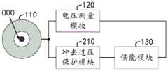
请参阅图2,为本申请实施例中一种取能与电流测量装置的另一结构示意图,该装置还包括冲击过压保护模块210。Please refer to FIG. 2 , which is another structural schematic diagram of an energy harvesting and current measuring device according to an embodiment of the present application. The device also includes a surge
其中,取能测量线圈110与冲击过压保护模块210、供能模块130依次连接。Wherein, the energy
在一种可行的实现方式中,取能测量线圈110还用于将交流感应电压传输至冲击过压保护模块210;冲击过压保护模块210用于在交流感应电压小于或等于预设阈值时,将交流感应电压传输至供能模块130。In a feasible implementation, the energy
其中,预设阈值是由操作人员根据实际需求选择的器件确定的,可以理解的是,在冲击过压保护模块210中可以有压敏电阻或其他器件,因此,在交流感应电压过大时或出现暂态过电压(即在雷击时出现的暂态过电压)时,压敏电阻会被击穿,从而使得电路呈现短路的状态,停止传输交流感应电压,以避免损坏其他电路模块中的器件。Among them, the preset threshold is determined by the device selected by the operator according to the actual demand. It is understandable that there may be a piezoresistor or other devices in the impulse
即在另一种可行的实现方式中,冲击过压保护模块210还用于在交流感应电压大于预设阈值时,停止传输交流感应电压。That is, in another feasible implementation manner, the surge
在本申请实施例中,通过冲击过压保护模块210提供过压保护,以将传输的交流感应电压保持在小于或等于预设阈值,从而避免损坏其他电路模块中的器件。In the embodiment of the present application, the overvoltage protection is provided by the surge
请参阅图3,为本申请实施例中一种取能与电流测量装置的另一结构示意图,供能模块130包括整流滤波模块310、直流调压稳压模块320和储能模块330。Please refer to FIG. 3 , which is another structural schematic diagram of an energy harvesting and current measuring device in an embodiment of the present application. The
其中,冲击过压保护模块210与整流滤波模块310、直流调压稳压模块320、储能模块330、电压测量模块120依次连接。Wherein, the impact
在一种可行的实现方式中,冲击过压保护模块210还用于在交流感应电压小于或等于预设阈值时,将交流感应电压传输至整流滤波模块310;整流滤波模块310用于将交流感应电压转换为直流电压,并将直流电压传输至直流调压稳压模块320;直流调压稳压模块320用于根据预设电压范围对直流电压进行调压处理得到直流稳压电压,并将直流稳压电压传输至储能模块330;储能模块330用于存储直流稳压电压,并为电压测量模块120提供电能。In a feasible implementation, the impulse
其中,预设电压范围是由操作人员根据实际需求进行设置的,可以理解的是,若存储的直流稳压电压5V的,则预设电压范围可以在5V±0.01V,此处不做限制。Wherein, the preset voltage range is set by the operator according to actual needs. It is understandable that if the stored DC voltage is 5V, the preset voltage range can be 5V±0.01V, which is not limited here.
需要说明的是,整流滤波模块310可以将交流感应电压转换为直流电压,直流调压稳压模块320可以将直流电压调压为预设电压范围的稳定且低纹波的直流稳压电压,从而使得所得到的直流稳压电压适合储能模块330进行存储及供能,进一步的,储能模块330不但可以为电压测量模块120提供电能,还可以为其他外部设备提供电能。It should be noted that the rectification and
进一步需要说明的是,存储模块330还用于在存储的直流稳压电压达到额定电压时,停止存储直流稳定电压,在存储的直流稳压电压小于额定电压时,再重新存储直流稳定电压。It should be further noted that the
在本申请实施例中,通过整流滤波模块310将交流感应电压转换为直流电压,以及通过直流调压稳压模块320将直流电压调压为预设电压范围的直流稳压电压,从而得到适合储能模块330进行存储及供能的直流稳压电压,且通过储能模块330存储直流稳压电压,并为电压测量模块120提供电能,以实现对交流感应电压进行测量,从而得到准确的电流测量结果,以最终实现电流测量。In the embodiment of the present application, the AC induction voltage is converted into a DC voltage through the rectification and
请参阅图4,为本申请实施例中一种取能与电流测量装置的另一结构示意图,该装置还包括能量泄放模块410、通信模块420。Please refer to FIG. 4 , which is another structural schematic diagram of an energy harvesting and current measuring device in an embodiment of the present application. The device also includes an
其中,冲击过压保护模块210与能量泄放模块410、整流滤波模块310依次连接,通信模块420分别与电压测量模块120、储能模块330连接。Wherein, the impulse
在一种可行的实现方式中,冲击过压保护模块210还用于在交流感应电压小于或等于预设阈值时,将交流感应电压传输至能量泄放模块410;能量泄放模块410用于将交流感应电压传输至整流滤波模块310;能量泄放模块410还用于在储能模块330存储的直流稳压电压达到额定电压时,消耗交流感应电压;电压测量模块120还用于将测量结果传输至通信模块420;通信模块420用于将测量结果传输至终端设备;储能模块330还用于为通信模块420提供电能。In a feasible implementation, the impulse
其中,额定电压是由储能模块330本身的器件所决定的,也可以由操作人员根据实际需求进行设置。Wherein, the rated voltage is determined by the components of the
需要说明的是,能量泄放模块410可以在储能模块330存储的直流稳压电压达到额定电压时,消耗交流感应电压,可以理解的是,在储能模块330存储的直流稳压电压达到额定电压时,可以将多余的电能通过能量泄放模块410进行泄放,以避免传输的交流感应电压过高,从而损坏其他电路模块中的器件;通信模块420可以将电压测量模块120的测量结果传输至终端设备,从而便于电力系统中的终端设备获取测量结果。It should be noted that the
在本申请实施例中,通过能量泄放模块410在储能模块330存储的直流稳压电压达到额定电压时,消耗交流感应电压,以将多余的电能进行泄放,以避免传输的交流感应电压过高,从而损坏其他电路模块中的器件;通过通信模块420将测量结果传输至终端设备,从而便于电力系统中的终端设备获取测量结果。In the embodiment of the present application, when the DC regulated voltage stored in the
请参阅图5,为本申请实施例中一种取能与电流测量装置的另一结构示意图,冲击过压保护模块210包括第一电容211、第二电容212、压敏电阻213。Please refer to FIG. 5 , which is another structural diagram of an energy harvesting and current measuring device in an embodiment of the present application. The surge
在一种可行的实现方式中,第一电容211的一端与压敏电阻213的一端连接,压敏电阻213的另一端与第二电容212的一端连接;第一电容211的另一端、第二电容212的另一端均与取能测量线圈110;压敏电阻213的两端均与能量泄放模块410连接。In a feasible implementation, one end of the
在本申请实施例中,通过第一电容211、第二电容212将交流感应电压进行滤波,使得输出的交流感应电压更为稳定;通过压敏电阻213使得输出的交流感应电压保持在小于或等于预设阈值,且当输出的交流感应电压大于预设阈值时,或者出现暂态过电压时,可以通过压敏电阻213,使得电路传输呈现短路状态,从而避免损坏其他电路模块中的器件。In the embodiment of the present application, the AC induced voltage is filtered through the
请继续参阅图5,能量泄放模块410包括第一电阻411、第一MOS管412、第一控制模块413。Please continue to refer to FIG. 5 , the
在一种可行的实现方式中,第一电阻411的一端与第一MOS管412的漏极端连接,第一MOS管412的栅极端与第一控制模块413连接;第一电阻411的另一端与压敏电阻213的一端连接,第一MOS管412的源极端与压敏电阻213的另一端连接;第一电阻411的另一端、第一MOS管412的源极端均与整流滤波模块310连接。In a feasible implementation, one end of the first resistor 411 is connected to the drain end of the
需要说明的是,第一MOS管412的初始状态为断开状态,第一控制模块413用于控制第一MOS管412的断开状态与导通状态,可以理解的是,第一控制模块413可以通过调整是否输出电压,或调整输出电压的电压值,从而控制第一MOS管412的断开状态和导通状态。It should be noted that the initial state of the
在本申请实施例中,当储能模块330存储的直流稳压电压达到额定电压时,通过第一控制模块413控制第一MOS管412导通,使得第一电阻411将电能转化为热能,从而消耗交流感应电压,以将多余的电能进行泄放,避免了传输的交流感应电压过高,从而损坏其他电路模块中的器件。In the embodiment of the present application, when the DC voltage stored in the
请继续参阅图5,整流滤波模块310包括第一二极管311、第二二极管312、第三二极管313、第四二极管314、第五二极管315。Please continue to refer to FIG. 5 , the rectification and
在一种可行的实现方式中,第一二极管311的阴极端分别与第二二极管312的阳极端、第三二极管313的阴极端连接,第三二极管313的阳极端与第四二极管314的阴极端连接,第四二极管314的阳极端与第五二极管的阳极端连接,第五二极管315的阴极端与第一二极管311的阳极端连接;第一二极管311的阳极端与第一电阻411的另一端连接,第三二极管313的阳极端与第一MOS管412的源极端连接;第二二极管312的阴极端、第四二极管314的阳极端均与直流调压稳压模块320连接。In a feasible implementation, the cathode terminal of the
在本申请实施例中,通过第一二极管311、第三二极管313、第四二极管314及第五二极管315的共同作用,以将交流感应电压转换为直流电压,从而便于后续将直流电压调压为适合存储及供能的直流稳定电压,以实现对外部设备进行供能;通过第二二极管312可以避免直流电压回流,导致其他电路模块中的器件受到损坏,且通过第二二极管312防止直流电压回流,以保证直流电压调压过程的稳定进行。In the embodiment of the present application, through the joint action of the
请继续参阅图5,直流调压稳压模块320包括电感321、第六二极管322、第二MOS管323、电压变换驱动模块324、第三电容325。Please continue to refer to FIG. 5 , the
在一种可行的实现方式中,电感321的一端分别与第六二极管322的阳极端、第二MOS管323的漏极端连接,第二MOS管323的栅极端与电压变换驱动模块324连接,第二MOS管323的源极与第三电容325的一端连接,第三电容325的另一端与第六二极管322的阴极端连接;电感321的另一端与第二二极管312的阴极端连接,第二MOS管323的源极端与第四二极管314的阳极端连接;第三电容325的两端均与储能模块330连接。In a feasible implementation, one end of the inductor 321 is respectively connected to the anode end of the
需要说明的是,电压变换驱动模块324用于控制第二MOS管323的断开状态与导通状态,可以理解的是,电压变换驱动模块324可以有规律的通过调整是否输出电压,或调整输出电压的电压值,从而有规律的控制第二MOS管323的断开状态和导通状态,即电压变换驱动模块324具有调控电压变换的功能。It should be noted that the voltage
在本申请实施例中,通过电感321、电压变换驱动模块324有规律的控制第二MOS管323的断开状态和导通状态、以及第三电容325共同的作用,以将直流电压调压为直流稳定电压,从而实现对外部设备进行供能;通过第六二极管322可以避免直流稳压电压回流,导致其他电路模块中的器件受到损坏。In the embodiment of the present application, the inductance 321, the voltage
请继续参阅图5,储能模块330包括第七二极管331、第八二极管332、第二电阻333、超级电容334、第三MOS管335、第二控制模块336。Please continue to refer to FIG. 5 , the
在一种可行的实现方式中,第七二极管331的阴极端分别与第八二极管332的阴极端、第二电阻333的一端连接,第二电阻333的另一端分别与第八二极管332的阳极端、超级电容334的一端连接,超级电容334的另一端与第三MOS管335的漏极端连接,第三MOS管335的栅极端与第二控制模块336连接;第七二极管331的阳极端与第三电容325的另一端连接,第三MOS管335的源极端与第三电容325的一端连接;第八二极管332的阴极端、超级电容334的另一端均分别与电压测量模块120、通信模块420连接。In a feasible implementation manner, the cathode terminal of the
需要说明的是,第三MOS管335的初始状态为导通状态,第二控制模块336用于控制第三MOS管335的断开状态与导通状态,可以理解的是,第二控制模块336可以通过调整是否输出电压,或调整输出电压的电压值,从而控制第三MOS管335的断开状态和导通状态。It should be noted that the initial state of the
进一步需要说明的是,在超级电容334存储的直流稳定电压达到额定电压时,It should be further noted that when the DC stable voltage stored in the
在本申请实施例中,通过第二电阻333降低存储的直流稳定电压的电流,使得直流稳定电压适合超级电容334的存储;在超级电容334存储的直流稳定电压达到额定电压时,第二控制模块336控制第三MOS管335断开,使得超级电容334停止充电,在采集电容334存储的直流稳定电压小于额定电压时,第二控制模块336控制第三MOS管335导通,使得超级电容334充电,既避免了过充过放,还能为外部设备持续的进行供能;通过第七二极管331、第八二极管332可以避免直流稳压电压回流及超级电容334放电的回流,导致其他电路模块中的器件受到损坏。In the embodiment of the present application, the current of the stored DC stabilized voltage is reduced by the
请继续参阅图5,电压测量模块120包括第三电阻121、第四电阻122、电压采样模块123;通信模块420包括信号传输模块421。Please continue to refer to FIG. 5 , the
在一种可行的实现方式中,第三电阻121的一端分别与第四电阻122的一端、电压采样模块123的第一端连接,电压采样模块123的第二端与第四电阻122的另一端连接;电压采样模块123的第三端与信号传输模块421的第一端连接;第三电阻121的另一端、第四电阻122的另一端均与取能测量线圈110的两端连接;电压采样模块123的第四端、信号传输模块421的第二端均与第八二极管332的阴极端连接,电压采样模块123的第五端、信号传输模块421的第三端均与超级电容334的另一端连接。In a feasible implementation, one end of the
需要说明的是,电压采样模块123是具有采集交流感应电压的电压波形及有效值,且将电压波形及有效值生成测量结果的电路模块,信号传输模块421是具有无线传输功能或有线传输功能的电路模块;例如:电压采样模块123可以类似示波器的电路模块,信号传输模块421类似于信号发生器的电路模块。It should be noted that the
在本申请实施例中,通过第三电阻121、第四电阻122形成分压,以避免电压采样模块123受到损坏;通过电压采样模块123采集第四电阻122的两端的电压,从而得到交流感应电压的电压波形及有效值,且将电压波形及有效值生成测量结果,从而得到准确的电流测量结果,以最终实现电流测量;通过信号传输模块421将测量结果传输至终端设备,从而便于电力系统中的终端设备获取测量结果。In the embodiment of the present application, the
以上实施例的各技术特征可以进行任意的组合,为使描述简洁,未对上述实施例中的各个技术特征所有可能的组合都进行描述,然而,只要这些技术特征的组合不存在矛盾,都应当认为是本说明书记载的范围。The technical features of the above embodiments can be combined arbitrarily. To make the description concise, all possible combinations of the technical features in the above embodiments are not described. However, as long as there is no contradiction in the combination of these technical features, they should be It is considered to be within the range described in this specification.
以上所述实施例仅表达了本申请的几种实施方式,其描述较为具体和详细,但并不能因此而理解为对本申请专利范围的限制。应当指出的是,对于本领域的普通技术人员来说,在不脱离本申请构思的前提下,还可以做出若干变形和改进,这些都属于本申请的保护范围。因此,本申请专利的保护范围应以所附权利要求为准。The above-mentioned embodiments only express several implementation modes of the present application, and the description thereof is relatively specific and detailed, but should not be construed as limiting the patent scope of the present application. It should be noted that those skilled in the art can make several modifications and improvements without departing from the concept of the present application, and these all belong to the protection scope of the present application. Therefore, the scope of protection of the patent application should be based on the appended claims.
Claims (10)
Priority Applications (1)
| Application Number | Priority Date | Filing Date | Title |
|---|---|---|---|
| CN202211423591.4ACN115684690A (en) | 2022-11-15 | 2022-11-15 | An energy harvesting and current measuring device |
Applications Claiming Priority (1)
| Application Number | Priority Date | Filing Date | Title |
|---|---|---|---|
| CN202211423591.4ACN115684690A (en) | 2022-11-15 | 2022-11-15 | An energy harvesting and current measuring device |
Publications (1)
| Publication Number | Publication Date |
|---|---|
| CN115684690Atrue CN115684690A (en) | 2023-02-03 |
Family
ID=85052123
Family Applications (1)
| Application Number | Title | Priority Date | Filing Date |
|---|---|---|---|
| CN202211423591.4APendingCN115684690A (en) | 2022-11-15 | 2022-11-15 | An energy harvesting and current measuring device |
Country Status (1)
| Country | Link |
|---|---|
| CN (1) | CN115684690A (en) |
Cited By (2)
| Publication number | Priority date | Publication date | Assignee | Title |
|---|---|---|---|---|
| CN116699216A (en)* | 2023-08-02 | 2023-09-05 | 武汉邢仪新未来电力科技股份有限公司 | Current transformer |
| CN119375531A (en)* | 2024-09-30 | 2025-01-28 | 珠海多创科技有限公司 | Current sensor, electronic device and current measuring method |
Citations (3)
| Publication number | Priority date | Publication date | Assignee | Title |
|---|---|---|---|---|
| CN104122428A (en)* | 2014-08-04 | 2014-10-29 | 青岛科汇电气有限公司 | Electronic current transformer adopting optical fiber transmission analog signals |
| CN107356801A (en)* | 2017-07-20 | 2017-11-17 | 云南电网有限责任公司电力科学研究院 | A kind of current measuring device and measuring method |
| CN216350955U (en)* | 2021-11-23 | 2022-04-19 | 苏州工业园区科佳自动化有限公司 | Wind generating set is from energy-taking lightning current monitoring system based on bluetooth |
- 2022
- 2022-11-15CNCN202211423591.4Apatent/CN115684690A/enactivePending
Patent Citations (3)
| Publication number | Priority date | Publication date | Assignee | Title |
|---|---|---|---|---|
| CN104122428A (en)* | 2014-08-04 | 2014-10-29 | 青岛科汇电气有限公司 | Electronic current transformer adopting optical fiber transmission analog signals |
| CN107356801A (en)* | 2017-07-20 | 2017-11-17 | 云南电网有限责任公司电力科学研究院 | A kind of current measuring device and measuring method |
| CN216350955U (en)* | 2021-11-23 | 2022-04-19 | 苏州工业园区科佳自动化有限公司 | Wind generating set is from energy-taking lightning current monitoring system based on bluetooth |
Cited By (3)
| Publication number | Priority date | Publication date | Assignee | Title |
|---|---|---|---|---|
| CN116699216A (en)* | 2023-08-02 | 2023-09-05 | 武汉邢仪新未来电力科技股份有限公司 | Current transformer |
| CN116699216B (en)* | 2023-08-02 | 2023-11-03 | 武汉邢仪新未来电力科技股份有限公司 | Current transformer |
| CN119375531A (en)* | 2024-09-30 | 2025-01-28 | 珠海多创科技有限公司 | Current sensor, electronic device and current measuring method |
Similar Documents
| Publication | Publication Date | Title |
|---|---|---|
| CN115684690A (en) | An energy harvesting and current measuring device | |
| CN110212594B (en) | Circuit CT energy acquisition and energy storage power supply | |
| CN114865760B (en) | An inductive power supply based on a non-closed magnetic core and a power supply method thereof | |
| CN109560578A (en) | A kind of device and method taking energy from ultra-high-tension power transmission line | |
| US11750026B2 (en) | System for harvesting power from a current transformer | |
| JP2003050637A (en) | Power supply | |
| CN101860084A (en) | High voltage side measurement system power supply | |
| CN109687540A (en) | A kind of electric wire magnetic field energy acquisition power supply | |
| CN101458266B (en) | Voltage source for high voltage dc transmission thyristor valve performance test | |
| CN106026424A (en) | Power supply system applied to power capacitor online monitoring system | |
| CN111917169B (en) | Power transmission line fault monitoring method and device based on dynamic electricity taking | |
| CN211127316U (en) | Current induction self-power-taking device and power distribution cabinet thereof | |
| CN112510851A (en) | High-voltage power taking circuit, device, control method and high-voltage power taking device | |
| CN204333983U (en) | Power supply device for wireless temperature sensor | |
| CN117200468A (en) | Sensor wide-range energy-taking conditioning method and circuit based on optocoupler automatic control | |
| CN205141824U (en) | Cubical switchboard modular power | |
| CN209593046U (en) | A kind of power supply circuit and weather station based on rechargeable battery | |
| CN209767367U (en) | self-powered circuit and control chip of switching power supply, switching power supply and electrical device | |
| CN208369292U (en) | Protect circuit and the charging equipment with the protection circuit | |
| CN117937782B (en) | Lightning arrester leakage current energy acquisition module and lightning arrester online monitoring equipment | |
| CN207074884U (en) | A kind of piezoelectric energy collecting circuit and piezoelectricity collector with decompression conversion | |
| CN119471014B (en) | A magnetic field energy-taking self-powered electromagnetic sensor and interference suppression method thereof | |
| CN222691574U (en) | A CT power supply circuit | |
| CN112946375B (en) | A lightning arrester monitoring device capable of measuring transferred charge | |
| CN217406248U (en) | Safety monitoring device for electrical equipment |
Legal Events
| Date | Code | Title | Description |
|---|---|---|---|
| PB01 | Publication | ||
| PB01 | Publication | ||
| SE01 | Entry into force of request for substantive examination | ||
| SE01 | Entry into force of request for substantive examination |