CN115682895B - Self-driven sensor and preparation method thereof - Google Patents
Self-driven sensor and preparation method thereofDownload PDFInfo
- Publication number
- CN115682895B CN115682895BCN202211703509.3ACN202211703509ACN115682895BCN 115682895 BCN115682895 BCN 115682895BCN 202211703509 ACN202211703509 ACN 202211703509ACN 115682895 BCN115682895 BCN 115682895B
- Authority
- CN
- China
- Prior art keywords
- electrode
- layer
- self
- electrodes
- sub
- Prior art date
- Legal status (The legal status is an assumption and is not a legal conclusion. Google has not performed a legal analysis and makes no representation as to the accuracy of the status listed.)
- Active
Links
Images


Landscapes
- Measurement Of Length, Angles, Or The Like Using Electric Or Magnetic Means (AREA)
Abstract
Translated fromChinese
Description
Translated fromChinese技术领域technical field
本发明属于人机交互技术领域,具体涉及一种自驱动传感器及其制备方法。The invention belongs to the technical field of human-computer interaction, and in particular relates to a self-driving sensor and a preparation method thereof.
背景技术Background technique
智能手机等便携电子设备的人机交互方式经历了从实体键盘到触摸屏的演变,加之虚拟现实等新兴技术也在近年不断涌现,人机交互操作方式不断趋向于提高操作体验与便利性,更加直观、高效、多样。但是,虚拟现实等交互技术实现起来较为复杂,而且需要昂贵的分体式佩戴设备,单从使用的便利性与成本来讲,虚拟现实等技术存在本征劣势。与此同时,传统键盘与触摸屏的交互界面局限在二维平(曲)面中的点按与画线,无法向三维空间扩展,限制了更多直观交互方式的应用。因此,需要一种既超越传统键盘与触摸屏感知能力范畴,又便于实现、可广泛应用的人机交互方式。The human-computer interaction mode of portable electronic devices such as smartphones has experienced the evolution from physical keyboards to touch screens. In addition, emerging technologies such as virtual reality have also emerged in recent years. The human-computer interaction operation mode continues to improve the operating experience and convenience, and is more intuitive , Efficient and diverse. However, interactive technologies such as virtual reality are more complicated to implement and require expensive split-type wearable devices. In terms of convenience and cost of use, technologies such as virtual reality have inherent disadvantages. At the same time, the interactive interface of traditional keyboards and touch screens is limited to clicking and drawing lines on a two-dimensional flat (curved) surface, which cannot be extended to three-dimensional space, which limits the application of more intuitive interactive methods. Therefore, there is a need for a human-computer interaction method that goes beyond the perception capabilities of traditional keyboards and touch screens, and is easy to implement and widely applicable.
摩擦电感知技术基于摩擦起电与静电感应效应的耦合,此前已广泛报道于压力传感等创新性研究。摩擦起电即为接触起电,日常生活当中无处不在的静电即由此产生,借助这一效应的普遍性,摩擦电感知技术具有非常广泛的应用范围。已有报道通常是基于两个带电物体之间的动态接触变化产生的电压输出,将这种电压输出作为自驱动感知信号,反映被测物体与传感器之间的接触压强或者压实程度,由此判断触点位置、受力分布、运动轨迹等二维平(曲)面内的信息,不具备感知被测物体三维静态位置的能力。Triboelectric sensing technology is based on the coupling of triboelectrification and electrostatic induction effects, which have been widely reported in innovative researches such as pressure sensing. Triboelectrification is contact electrification, from which the ubiquitous static electricity in daily life is generated. With the universality of this effect, triboelectric sensing technology has a very wide range of applications. Previous reports are usually based on the voltage output generated by the dynamic contact change between two charged objects, and this voltage output is used as a self-driven sensing signal to reflect the contact pressure or degree of compaction between the measured object and the sensor, thus It does not have the ability to perceive the three-dimensional static position of the measured object to judge the information in the two-dimensional flat (curved) surface such as the contact position, force distribution, and motion trajectory.
因此,目前的应用于人机交互设备的传感器设计不合理,不具备感知被测物体三维静态位置的能力。Therefore, the current sensors used in human-computer interaction devices are unreasonably designed and do not have the ability to perceive the three-dimensional static position of the measured object.
发明内容Contents of the invention
本发明旨在至少解决现有技术中存在的技术问题之一,提供一种自驱动传感器及其制备方法的新技术方案。The present invention aims to solve at least one of the technical problems existing in the prior art, and provides a new technical solution of a self-driven sensor and a preparation method thereof.
根据本申请的第一方面,提供一种自驱动传感器,包括:According to a first aspect of the present application, a self-driven sensor is provided, comprising:
衬底层;substrate layer;
电极图案层,所述电极图案层包括第一电极层、第二电极层和绝缘层;所述第一电极层设置于所述衬底层的表面;所述第一电极层包括多个第一电极,多个所述第一电极沿第一方向阵列排布;所述第二电极层通过所述绝缘层设置于所述第一电极层的上方,所述第二电极层包括多个第二电极,多个所述第二电极沿第二方向阵列排布,所述绝缘层位于所述第一电极与所述第二电极相对应的位置处;An electrode pattern layer, the electrode pattern layer includes a first electrode layer, a second electrode layer and an insulating layer; the first electrode layer is arranged on the surface of the substrate layer; the first electrode layer includes a plurality of first electrodes , a plurality of the first electrodes are arranged in an array along the first direction; the second electrode layer is arranged above the first electrode layer through the insulating layer, and the second electrode layer includes a plurality of second electrodes , a plurality of the second electrodes are arranged in an array along the second direction, and the insulating layer is located at a position corresponding to the first electrode and the second electrode;
电压读取单元,每个所述第一电极均连接有一个所述电压读取单元,每个所述第二电极均连接有一个所述电压读取单元;A voltage reading unit, each of the first electrodes is connected to one of the voltage reading units, and each of the second electrodes is connected to one of the voltage reading units;
当被测物体靠近所述电极图案层的某一位置时,在静电感应的作用下,所述第一电极层和第二电极层发生电势变化并通过电压读取单元输出自驱动感知信号;其中,电势变化量与被测物体与电极图案层的距离呈正相关,且根据发生电势变化的第一电极和第二电极获取被测物体的位置信息。When the measured object is close to a certain position of the electrode pattern layer, under the action of electrostatic induction, the potential of the first electrode layer and the second electrode layer changes and outputs a self-driven sensing signal through the voltage reading unit; wherein, The amount of potential change is positively correlated with the distance between the measured object and the electrode pattern layer, and the position information of the measured object is obtained according to the first electrode and the second electrode where the potential change occurs.
可选地,自驱动传感器还包括保护层,所述保护层覆盖所述电极图案层远离衬底层的一侧。Optionally, the self-driven sensor further includes a protective layer, and the protective layer covers a side of the electrode pattern layer away from the substrate layer.
可选地,所述保护层的材质为防水材质。Optionally, the protective layer is made of waterproof material.
可选地,所述保护层的表面设置微纳米多孔结构。Optionally, a micro-nano porous structure is provided on the surface of the protective layer.
可选地,所述第一电极包括多个依次相连的第一子电极,所述第二电极包括多个依次相连的第二子电极,所述绝缘层包括多个绝缘单元;Optionally, the first electrode includes a plurality of sequentially connected first sub-electrodes, the second electrode includes a plurality of sequentially connected second sub-electrodes, and the insulating layer includes a plurality of insulating units;
相邻的两个第一子电极的连接处形成第一连接点,相邻的两个第二子电极的连接处形成第二连接点,每个所述第一连接点对应一个所述第二连接点,所述绝缘单元连接所述第一连接点和所述第二连接点。The connection of two adjacent first sub-electrodes forms a first connection point, and the connection of two adjacent second sub-electrodes forms a second connection point, and each of the first connection points corresponds to one of the second A connection point, the insulation unit connects the first connection point and the second connection point.
可选地,所述第一子电极的形状为菱形、矩形、圆形或星形。例如,第一子电极在衬底层表面的投影与第二子电极在衬底层表面的投影不重叠。进一步地,在此基础上应以第一子电极和第二子电极可最大面积覆盖衬底层的传感区域为首要原则。Optionally, the shape of the first sub-electrode is rhombus, rectangle, circle or star. For example, the projection of the first sub-electrode on the surface of the substrate layer does not overlap with the projection of the second sub-electrode on the surface of the substrate layer. Further, on this basis, the first principle should be that the first sub-electrode and the second sub-electrode can cover the sensing area of the substrate layer with the largest area.
可选地,所述第一方向与所述第二方向垂直设置。Optionally, the first direction is perpendicular to the second direction.
可选地,所述衬底层的材质为绝缘材质,且所述衬底层为柔性衬底或者硬质衬底。Optionally, the material of the substrate layer is an insulating material, and the substrate layer is a flexible substrate or a hard substrate.
根据本申请的第二方面,提供一种自驱动传感器的制备方法,用于制备如第一方面所述的自驱动传感器,包括如下步骤:According to the second aspect of the present application, there is provided a method for preparing a self-driven sensor, which is used to prepare the self-driven sensor as described in the first aspect, comprising the following steps:
步骤100,在衬底层上形成图案化的第一电极层;Step 100, forming a patterned first electrode layer on the substrate layer;
步骤200,在第一电极层上形成图案化的绝缘层,在绝缘层上形成图案化的第二电极层;Step 200, forming a patterned insulating layer on the first electrode layer, and forming a patterned second electrode layer on the insulating layer;
步骤300,在衬底层的表面形成覆盖第一电极层以及第二电极层的保护层;Step 300, forming a protective layer covering the first electrode layer and the second electrode layer on the surface of the substrate layer;
步骤400,将每个第一电极层的第一电极连接电压读取单元,并将每个第二电极层的第二电极连接电压读取单元。Step 400, connect the first electrode of each first electrode layer to the voltage reading unit, and connect the second electrode of each second electrode layer to the voltage reading unit.
可选地,自驱动传感器的制备方法还包括:Optionally, the preparation method of the self-driven sensor also includes:
步骤500,将被测物体与保护层的表面触摸后分离,通过接触起电效应使被测物体与保护层的表面分别达到稳定的电荷分布,然后,将各个第一电极和各个第二电极分别接地一次。Step 500, separate the measured object from the surface of the protective layer after touching, and make the measured object and the surface of the protective layer respectively achieve stable charge distribution through the contact electrification effect, and then separate each first electrode and each second electrode Ground once.
本发明的一个技术效果在于:A technical effect of the present invention is:
在本申请实施例中,当被测物体靠近电极图案层的某一位置时,在静电感应的作用下,第一电极层和第二电极层发生电势变化并通过电压读取单元输出自驱动感知信号;其中,电势变化量与被测物体与电极图案层的距离呈正相关,且根据发生电势变化的第一电极和第二电极获取被测物体的位置信息。因此,可以通过电势的变化量以及发生电势变化的第一电极和第二电极准确地感知距离该自驱动传感器一定距离范围内的各个物体在三维空间的位置及变化。In the embodiment of the present application, when the measured object is close to a certain position of the electrode pattern layer, under the action of electrostatic induction, the potential of the first electrode layer and the second electrode layer changes and outputs a self-driving sensing signal through the voltage reading unit ; Wherein, the potential change amount is positively correlated with the distance between the measured object and the electrode pattern layer, and the position information of the measured object is obtained according to the first electrode and the second electrode where the potential change occurs. Therefore, the position and change of each object in a three-dimensional space within a certain distance from the self-driven sensor can be accurately sensed through the change amount of the potential and the first electrode and the second electrode where the potential change occurs.
该自驱动传感器不仅突破传统键盘、触摸屏等人机交互界面只能感知二维面内的点按、划线等交互信息的局限;而且,结构非常简单,操作方便,其不需要类似于虚拟现实技术那样佩戴于周身的分体式复杂设备;同时,该自驱动传感器的传感功能集中在一个平面式阵列当中,且采用层状堆叠结构,易于制备和应用。The self-driven sensor not only breaks through the limitations of traditional human-computer interaction interfaces such as keyboards and touch screens, which can only perceive interactive information such as clicks and lines in two-dimensional surfaces; moreover, the structure is very simple and easy to operate, and it does not need to It is a split-type complex device worn around the body like technology; at the same time, the sensing function of the self-driven sensor is concentrated in a planar array, and it adopts a layered stack structure, which is easy to prepare and apply.
综上,该自驱动传感器在形式上仅为类似普通触摸屏的二维平面,但可以基于摩擦电效应感知一定距离范围内的各个物体在三维空间的位置及变化,能够作为新型的人机交互界面,使得手势操控等交互方式以易于应用的方式扩展到三维空间,带来更加直观的操作方式和便利体验。In summary, the self-driven sensor is only a two-dimensional plane similar to an ordinary touch screen in form, but it can perceive the position and change of each object within a certain distance in three-dimensional space based on the triboelectric effect, and can be used as a new type of human-computer interaction interface. , so that interactive methods such as gesture control can be extended to three-dimensional space in an easy-to-apply manner, bringing more intuitive operation methods and convenient experience.
附图说明Description of drawings
图1为本发明一实施例的一种自驱动传感器的第一电极层的结构示意图;FIG. 1 is a schematic structural diagram of a first electrode layer of a self-driven sensor according to an embodiment of the present invention;
图2为本发明一实施例的一种自驱动传感器的绝缘层的结构示意图;2 is a schematic structural diagram of an insulating layer of a self-driven sensor according to an embodiment of the present invention;
图3为本发明一实施例的一种自驱动传感器的第二电极层叠置于第一电极层的俯视图;3 is a top view of a self-driven sensor in which the second electrode layer is stacked on the first electrode layer according to an embodiment of the present invention;
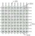
图4为本发明一实施例的一种自驱动传感器的对第一电极和第二电极编号的结构示意图;Fig. 4 is a structural schematic diagram of numbering the first electrode and the second electrode of a self-driven sensor according to an embodiment of the present invention;
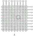
图5为被测物体靠近图4中A处的示意图;Fig. 5 is a schematic diagram of the measured object close to A in Fig. 4;
图6为图4的剖面结构示意图。FIG. 6 is a schematic cross-sectional structure diagram of FIG. 4 .
图中:1、衬底层;21、第一电极层;211、第一电极;2111、第一子电极;22、第二电极层;221、第二电极;2211、第二子电极;23、绝缘单元;3、电压读取单元;4、保护层;5、被测物体。In the figure: 1, substrate layer; 21, first electrode layer; 211, first electrode; 2111, first sub-electrode; 22, second electrode layer; 221, second electrode; 2211, second sub-electrode; 23, Insulation unit; 3. Voltage reading unit; 4. Protective layer; 5. Object to be measured.
具体实施方式Detailed ways
现在将参照附图来详细描述本申请的各种示例性实施例。应注意到:除非另外具体说明,否则在这些实施例中阐述的部件和步骤的相对布置、数字表达式和数值不限制本申请的范围。Various exemplary embodiments of the present application will now be described in detail with reference to the accompanying drawings. It should be noted that the relative arrangements of components and steps, numerical expressions and numerical values set forth in these embodiments do not limit the scope of the present application unless specifically stated otherwise.
下面将详细描述本申请的实施例,所述实施例的示例在附图中示出,其中自始至终相同或类似的标号表示相同或类似的元件或具有相同或类似功能的元件。下面通过参考附图描述的实施例是示例性的,仅用于解释本申请,而不能理解为对本申请的限制。基于本申请中的实施例,本领域普通技术人员在没有作出创造性劳动前提下所获得的所有其他实施例,都属于本申请保护的范围。Embodiments of the present application will be described in detail below, examples of which are shown in the drawings, in which the same or similar reference numerals denote the same or similar elements or elements having the same or similar functions throughout. The embodiments described below by referring to the figures are exemplary, are only for explaining the present application, and should not be construed as limiting the present application. Based on the embodiments in this application, all other embodiments obtained by persons of ordinary skill in the art without creative efforts fall within the protection scope of this application.
本申请的说明书和权利要求书中的术语“第一”、“第二”的特征可以明示或者隐含地包括一个或者更多个该特征。在本申请的描述中,除非另有说明,“多个”的含义是两个或两个以上。此外,说明书以及权利要求中“和/或”表示所连接对象的至少其中之一,字符“/”,一般表示前后关联对象是一种“或”的关系。The features of the terms "first" and "second" in the description and claims of the present application may explicitly or implicitly include one or more of these features. In the description of the present application, unless otherwise specified, "plurality" means two or more. In addition, "and/or" in the specification and claims means at least one of the connected objects, and the character "/" generally means that the related objects are an "or" relationship.
在本申请的描述中,需要理解的是,术语“中心”、“纵向”、“横向”、“长度”、“宽度”、“厚度”、“上”、“下”、“前”、“后”、“左”、“右”、“竖直”、“水平”、“顶”、“底”“内”、“外”、“顺时针”、“逆时针”、“轴向”、“径向”、“周向”等指示的方位或位置关系为基于附图所示的方位或位置关系,仅是为了便于描述本申请和简化描述,而不是指示或暗示所指的装置或元件必须具有特定的方位、以特定的方位构造和操作,因此不能理解为对本申请的限制。In the description of the present application, it should be understood that the terms "center", "longitudinal", "transverse", "length", "width", "thickness", "upper", "lower", "front", " Back", "Left", "Right", "Vertical", "Horizontal", "Top", "Bottom", "Inner", "Outer", "Clockwise", "Counterclockwise", "Axial", The orientation or positional relationship indicated by "radial", "circumferential", etc. is based on the orientation or positional relationship shown in the drawings, and is only for the convenience of describing the application and simplifying the description, rather than indicating or implying the referred device or element Must be in a particular orientation, constructed, and operate in a particular orientation, and thus should not be construed as limiting of the application.
在本申请的描述中,需要说明的是,除非另有明确的规定和限定,术语“安装”、“相连”、“连接”应做广义理解,例如,可以是固定连接,也可以是可拆卸连接,或一体地连接;可以是机械连接,也可以是电连接;可以是直接相连,也可以通过中间媒介间接相连,可以是两个元件内部的连通。对于本领域的普通技术人员而言,可以具体情况理解上述术语在本申请中的具体含义。In the description of this application, it should be noted that unless otherwise specified and limited, the terms "installation", "connection", and "connection" should be understood in a broad sense, for example, it can be a fixed connection or a detachable connection. Connected, or integrally connected; it may be mechanically connected or electrically connected; it may be directly connected or indirectly connected through an intermediary, and it may be the internal communication of two components. Those of ordinary skill in the art can understand the specific meanings of the above terms in this application in specific situations.
参见图1至图6,根据本申请的第一方面,提供一种自驱动传感器,其包括衬底层1、电极图案层和电压读取单元3。Referring to FIGS. 1 to 6 , according to a first aspect of the present application, a self-driven sensor is provided, which includes a
具体地,所述电极图案层包括第一电极层21、第二电极层22和绝缘层;所述第一电极层21设置于所述衬底层1的表面;所述第一电极层21包括多个第一电极211,多个所述第一电极211沿第一方向阵列排布;所述第二电极层22通过所述绝缘层设置于所述第一电极层21的上方,所述第二电极层22包括多个第二电极221,多个所述第二电极221沿第二方向阵列排布,所述绝缘层位于所述第一电极211与所述第二电极221相对应的位置处。Specifically, the electrode pattern layer includes a
在一个具体的实施方式中,第一电极层21和第二电极层22的图案相同,两者的不同之处在于,第一电极层21的排布方式和阵列方向与第二电极层22的排布方式和阵列方向不同。In a specific embodiment, the patterns of the
进一步具体地,每个所述第一电极211均连接有一个所述电压读取单元3,每个所述第二电极221均连接有一个所述电压读取单元3。More specifically, each of the
当被测物体5靠近所述电极图案层的某一位置时,在静电感应的作用下,所述第一电极层21和第二电极层22发生电势变化并通过电压读取单元3输出自驱动感知信号;其中,电势变化量与被测物体5与电极图案层的距离呈正相关,且根据发生电势变化的第一电极211和第二电极221获取被测物体5的位置信息。When the measured
在本申请实施例中,该自驱动传感器能够感知物体三维位置,其可以应用于近距离感知手部静态动作等三维空间信息等能力,且该自驱动传感器的结构简单,其外观依然是二维平面形式,不需要类似于虚拟现实技术中复杂且数量众多的配套设备,可广泛应用于日常使用环境中,使用非常方便。In the embodiment of the present application, the self-driving sensor can perceive the three-dimensional position of the object, which can be applied to the ability to perceive three-dimensional space information such as the static movement of the hand at close range, and the structure of the self-driving sensor is simple, and its appearance is still two-dimensional The flat form does not require complex and numerous supporting equipment similar to that in virtual reality technology, and can be widely used in daily use environments, and it is very convenient to use.
可选地,参见图6,自驱动传感器还包括保护层4,所述保护层4覆盖所述电极图案层远离衬底层的一侧。保护层4能够较好地保护电极图案层,增强自驱动传感器对环境的适应性,保证自驱动传感器安全且稳定的运行。保护层4能够大福提高第一电极211和第二电极221的耐用程度,防止外部接触引起电极损坏。Optionally, referring to FIG. 6 , the self-driven sensor further includes a
需要说明的是,根据接触起电效应,被测物体5比如手指等人体部位以及常见物体在日常环境中都会因为接触其他物体而带有表面电荷,电荷根据物体表面形状尽可能地分布在尖端。以人体为例,人体与地面、衣物等日常接触摩擦而带有电荷,这些电荷又因表面形状通常集中分布在手指等部位上。这些通常分布有表面电荷的带电物体或人体部位接近自驱动传感器时,通过静电感应将引起自驱动传感器的第一电极211和第二电极221的电势产生变化。同时,第一电极211和第二电极221均与电压读取单元3连接,电压读取单元3所读取的电压的变化即反映了被测物体5与自驱动传感器的距离信息。进一步地,多个第一电极211沿第一方向阵列排布,多个第二电极221沿第二方向阵列排布,每个阵列点对应一个平面坐标,综合各坐标点的电压信号即可得知自驱传感器附近带电的被测物体5的三维空间位置及变化。此外,通过在传感器表面增加疏水功能的保护层4,增强对潮湿环境的适应性。It should be noted that according to the contact electrification effect, the measured
可选地,所述保护层4的材质为防水材质。保护层4能够较好地增强自驱动传感器对湿度环境的适应性。使用防水材质的保护层4,或在衬底层1的表面涂敷防水涂层以形成保护层4,均可以增强自驱动传感器在湿度环境下的性能稳定。保护层4可根据透光度、装饰性、防护性等具体要求进行选择,例如,采用PDMS、二维材料/防水修饰层复合材料等。Optionally, the
可选地,所述保护层4的表面设置微纳米多孔结构,或者以其他方式增强疏水性。比如,在衬底层1的表面旋涂PDMS(聚二甲基硅氧烷),PDMS加热固化后形成保护层4,可采用激光刻蚀的方式在保护层4的表面形成微纳米多孔结构,从而能够较好地增强保护层4的疏水性能。Optionally, the surface of the
可选地,所述第一电极211包括多个依次相连的第一子电极2111,所述第二电极221包括多个依次相连的第二子电极2211,所述绝缘层包括多个绝缘单元23;Optionally, the
相邻的两个第一子电极2111的连接处形成第一连接点,相邻的两个第二子电极2211的连接处形成第二连接点,每个所述第一连接点对应一个所述第二连接点,所述绝缘单元23连接所述第一连接点和所述第二连接点。The connection between two adjacent first sub-electrodes 2111 forms a first connection point, and the connection between two adjacent second sub-electrodes 2211 forms a second connection point, and each of the first connection points corresponds to one of the The second connection point, the insulating
在上述实施方式中,第一电极211和第二电极221的结构比较简单,通过绝缘层能够将第二电极221固定在第一电极211上,同时能够保证第一电极211和第二电极221之间的绝缘。In the above embodiment, the structure of the
可选地,所述第一子电极2111的形状为菱形、矩形、圆形或星形等,且所述第二子电极2211与所述第一子电极2111的形状可以相同,也可以不相同。这使得第一子电极2111和第二子电极2211的形状多样化,可以根据用户的需求选择第一子电极2111和第二子电极2211的形状。Optionally, the shape of the first sub-electrode 2111 is rhombus, rectangle, circle or star, and the shape of the second sub-electrode 2211 and the first sub-electrode 2111 may or may not be the same . This makes the shapes of the first sub-electrodes 2111 and the second sub-electrodes 2211 diversified, and the shapes of the first sub-electrodes 2111 and the second sub-electrodes 2211 can be selected according to user's needs.
在其他实施方式中,第一子电极2111和第二子电极2211可以为其他的形状,只要能够实现第一电极层21和第二电极层22对待测物体的位置感知即可。In other embodiments, the first sub-electrode 2111 and the second sub-electrode 2211 may have other shapes, as long as the
可选地,所述第一方向与所述第二方向垂直设置。这使得第一电极层21和第二电极层22能够较好地感知待测物体的位置,从而保证自驱动传感器检测的准确性。Optionally, the first direction is perpendicular to the second direction. This enables the
在一个具体的是方式中,第一子电极2111和第二子电极2211的形状为菱形,且第一方向与第二方向垂直设置,这使得第一子电极2111和第二子电极2211能够较好地布满衬底的整个表面,从而有助于保证自驱动传感器检测的准确性。In a specific way, the shape of the first sub-electrode 2111 and the second sub-electrode 2211 is a rhombus, and the first direction is perpendicular to the second direction, which makes the first sub-electrode 2111 and the second sub-electrode 2211 can be compared The entire surface of the substrate is well covered, which helps to ensure the accuracy of self-driven sensor detection.
可选地,所述衬底层1的材质为绝缘材质,且所述衬底层1为柔性衬底或者硬质衬底。这使得衬底层1的材质的选择灵活,可以根据自驱动传感器具体的应用场景进行选择,使用非常方便。Optionally, the material of the
当绝缘衬底为柔性衬底时,其可以为PET(聚对苯二甲酸乙二醇酯)、kapton(聚酰亚胺)、PDMS(聚二甲基硅氧烷)等绝缘材料;当绝缘衬底为硬质衬底,其可以为氧化硅片、硬质塑料、玻璃等。When the insulating substrate is a flexible substrate, it can be insulating materials such as PET (polyethylene terephthalate), kapton (polyimide), PDMS (polydimethylsiloxane); when insulating The substrate is a hard substrate, which can be silicon oxide wafer, hard plastic, glass and so on.
根据本申请的第二方面,提供一种自驱动传感器的制备方法,用于制备如第一方面所述的自驱动传感器,包括如下步骤:According to the second aspect of the present application, there is provided a method for preparing a self-driven sensor, which is used to prepare the self-driven sensor as described in the first aspect, comprising the following steps:
步骤100,在衬底层1上形成图案化的第一电极层21。Step 100 , forming a patterned
参见图1,第一电极211沿横向延伸并沿纵向阵列以形成第一电极层21。具体地,在清洗干净的衬底层1(例如玻璃)上旋涂光刻胶,经光刻、显影后形成第一电极层21的图案。在带有第一电极层21图案的衬底层1上磁控溅射生长ITO薄膜透明电极,经去胶剥离和清洗后得到图案化的第一电极层21。Referring to FIG. 1 , the
步骤200,在第一电极层21上形成图案化的绝缘层,在绝缘层上形成图案化的第二电极层22。In step 200, a patterned insulating layer is formed on the
具体地,制备图案化的绝缘层。示例性地,第一子电极2111和第二子电极2211均为菱形,相邻两个第一子电极2111的连接处制备绝缘单元23,多个绝缘单元23构成图案化的绝缘层,参见图2。例如,采用旋涂光刻胶后曝光、显影的方式形成绝缘层的图案,物理沉积方法生长二氧化硅薄膜,经过去胶剥离和清洗后得到图案化的绝缘层。Specifically, a patterned insulating layer is prepared. Exemplarily, the first sub-electrode 2111 and the second sub-electrode 2211 are rhombus-shaped, and an insulating
进一步地,在形成有第一电极层21和绝缘层的衬底层1上制备图案化的第二电极层22,图案化方式为光刻法。例如,形成第二电极层22的图案如图3所示;然后,沉积ITO薄膜透明电极,经过去胶剥离和清洗后得到的第二电极221与第一电极211交错排列但互相绝缘。即第二电极221沿纵向延伸并沿横向阵列以形成第二电极层22。Further, a patterned
步骤300,在衬底层1的表面形成覆盖第一电极层21以及第二电极层22的保护层4。保护层4能够较好地保护电极图案层。Step 300 , forming a
步骤400,将每个第一电极层21的第一电极211连接电压读取单元3,并将每个第二电极层22的第二电极221连接电压读取单元3。Step 400 , connect the
在上述实施方式中,自驱动传感器的制备方法非常简单,而且制得的自驱动传感器具备感知二维与三维操作信息的能力,其物理形状仅为二维平面(曲面)形式,形式简单且功能集成度高。In the above embodiments, the preparation method of the self-driven sensor is very simple, and the prepared self-driven sensor has the ability to perceive two-dimensional and three-dimensional operation information, and its physical shape is only in the form of a two-dimensional plane (curved surface), which is simple in form and functional High integration.
图1至图3仅是对自驱动传感器的第一电极211和第二电极221的某个样式进行展示,其不对第一电极层21或第二电极层22的图案的具体样式产生任何限制,每个第一子电极2111以及第二子电极2211的形状可以但不限于方形、矩形、圆形、星形等形状,第一电极211和第二电极221的阵列排布方式可以但不限于横平竖直、隔行/列交错等形式。第一电极层21和第二电极层22的图案化可以采用掩膜、光刻、激光直写、喷墨打印、3D打印、刻蚀等图案化方法。第一电极层21和第二电极层22的制备可采用化学法薄膜沉积、物理法薄膜沉积、导电材料转移、导电材料转印、导电材料涂敷等各种方式。FIGS. 1 to 3 only show a certain pattern of the
可选地,自驱动传感器的制备方法还包括:Optionally, the preparation method of the self-driven sensor also includes:
步骤500,将被测物体5与保护层4的表面触摸后分离,通过接触起电效应使被测物体5与保护层4的表面分别达到稳定的电荷分布,从而能够增强信号输出和自驱动传感器的性能稳定;然后,将各个第一电极211和各个第二电极221分别接地一次,便于后续第一电极211以及第二电极221的电位变化的测量。Step 500, separate the measured
在本申请实施例中,该自驱动传感器的使用与电压信号输出如下:In the embodiment of this application, the use and voltage signal output of the self-driven sensor are as follows:
第一电极211(横向电极)和第二电极221(纵向电极)可通过各自编号进行区分,如附图4所示,每个第一电极211和第二电极221之间互相绝缘,第一电极211和第二电极221覆盖整个传感阵列区域。每个横向电极和纵向电极各自与一个电压读取单元3通路相连接,如附图5所示。经过步骤500之后,被测物体5与自驱动传感器表面的保护层4(PDMS)带有互相异号的电荷。当被测物体5再次接近自驱动传感器时,由于静电感应的存在,自驱动传感器对应位置的第一电极211和第二电极221将产生电势变化,电势变化反映被测物体5距离的远近,此外根据发生电势变化的第一电极211和第二电极221的编号则可以揭示出带电的被测物体5的具体位置。The first electrodes 211 (horizontal electrodes) and the second electrodes 221 (longitudinal electrodes) can be distinguished by their respective numbers. As shown in Figure 4, each
参见图4和图5,当被测物体5(如手指)接近图4中A位置附近时,手指与自驱动传感器越近则自驱动传感器输出的电势变化越大,根据电势的变化可以判断手指与自驱动传感器的距离。同时,与手指距离最近的横向电极L5和纵向电极C4将产生最大的电势变化响应,由此可以判断出手指在图4中A位置的上方附近位置。当多个手指接近自驱动传感器时,则根据不同手指附近电极电势响应的大小以及第一电极211和第二电极221交点位置即可识别手势动作悬停和变化。此外,当手指与自驱动传感器靠近过程中,两者接触时引起的电荷变化最大,因此也可用于以接触模式实现普通触摸屏的对点击、划线等二维面内操作信息的感知功能。Referring to Figure 4 and Figure 5, when the measured object 5 (such as a finger) is close to the position A in Figure 4, the closer the finger is to the self-driving sensor, the greater the change in the potential output from the self-driving sensor, and the finger can be judged according to the change in potential Distance from self-driving sensor. At the same time, the horizontal electrode L5 and the vertical electrode C4 closest to the finger will produce the largest potential change response, so it can be judged that the finger is near the top of the position A in FIG. 4 . When multiple fingers approach the self-driving sensor, the hovering and changing of the gesture can be recognized according to the magnitude of the electrode potential response near different fingers and the position of the intersection of the
需要说明的是,该自驱动传感器具有如下应用场景:It should be noted that the self-driving sensor has the following application scenarios:
场景一:应用于智能手机等电子设备。衬底层1选用透明玻璃,电极图案层和绝缘层分别采用透明材料,则可以使智能手机的触摸屏具备三维感知能力,而不再依赖摄像头等耗能高的光学信息组件提供对用户靠近手机、用户手势识别等信息的感知,从而显著增强智能手机等电子设备操作便利性,提供更低功耗、更低成本、更便利的新型人机交互方式。Scenario 1: Applied to electronic devices such as smartphones. The
场景二:应用于智能机器人。智能机器人的机械手的手部活动往往复杂且自由度高,难以通过直观的方式对机械手进行控制,通过自驱动传感器能够操控智能机器人的机械手,从而将获得极大的便利性。例如,操作者只需要在自驱动传感器附近做出手势动作,自驱动传感器感知操作者的手指在三维空间的位置变化便可通过计算得出操作者的完整手势,进而指挥机械手同步跟随。Scenario 2: Applied to intelligent robots. The hand movement of the manipulator of the intelligent robot is often complicated and has a high degree of freedom, and it is difficult to control the manipulator in an intuitive way. The manipulator of the intelligent robot can be controlled through the self-driving sensor, which will obtain great convenience. For example, the operator only needs to make a gesture near the self-driving sensor, and the self-driving sensor can sense the position change of the operator's finger in three-dimensional space to calculate the operator's complete gesture, and then command the manipulator to follow it synchronously.
可以理解的是,以上实施方式仅仅是为了说明本发明的原理而采用的示例性实施方式,然而本发明并不局限于此。对于本领域内的普通技术人员而言,在不脱离本发明的精神和实质的情况下,可以做出各种变型和改进,这些变型和改进也视为本发明的保护范围。It can be understood that, the above embodiments are only exemplary embodiments adopted for illustrating the principle of the present invention, but the present invention is not limited thereto. For those skilled in the art, various modifications and improvements can be made without departing from the spirit and essence of the present invention, and these modifications and improvements are also regarded as the protection scope of the present invention.
Claims (7)
Priority Applications (1)
| Application Number | Priority Date | Filing Date | Title |
|---|---|---|---|
| CN202211703509.3ACN115682895B (en) | 2022-12-29 | 2022-12-29 | Self-driven sensor and preparation method thereof |
Applications Claiming Priority (1)
| Application Number | Priority Date | Filing Date | Title |
|---|---|---|---|
| CN202211703509.3ACN115682895B (en) | 2022-12-29 | 2022-12-29 | Self-driven sensor and preparation method thereof |
Publications (2)
| Publication Number | Publication Date |
|---|---|
| CN115682895A CN115682895A (en) | 2023-02-03 |
| CN115682895Btrue CN115682895B (en) | 2023-04-07 |
Family
ID=85055800
Family Applications (1)
| Application Number | Title | Priority Date | Filing Date |
|---|---|---|---|
| CN202211703509.3AActiveCN115682895B (en) | 2022-12-29 | 2022-12-29 | Self-driven sensor and preparation method thereof |
Country Status (1)
| Country | Link |
|---|---|
| CN (1) | CN115682895B (en) |
Family Cites Families (11)
| Publication number | Priority date | Publication date | Assignee | Title |
|---|---|---|---|---|
| WO2008135713A1 (en)* | 2007-05-07 | 2008-11-13 | Qrg Limited | Two-dimensional position sensor |
| KR101685902B1 (en)* | 2010-09-15 | 2016-12-13 | 삼성전자주식회사 | Touch sensing appratus and method for sensing approach |
| JP5888686B2 (en)* | 2012-11-26 | 2016-03-22 | 学校法人福岡大学 | Proximity / contact sensor |
| CN103411710B (en)* | 2013-08-12 | 2016-04-06 | 北京纳米能源与系统研究所 | A kind of pressure transducer, electronic skin and touch-screen equipment |
| CN104748769B (en)* | 2013-12-25 | 2017-08-04 | 北京纳米能源与系统研究所 | A sensor and sensing method based on electrostatic induction |
| CN105091913B (en)* | 2014-04-18 | 2018-02-16 | 北京纳米能源与系统研究所 | Sensor and method for sensing based on electrostatic induction |
| CN106382997B (en)* | 2016-09-18 | 2019-08-09 | 北京科技大学 | A frictional electrostatic induction electronic skin |
| CN108240877B (en)* | 2016-12-23 | 2021-04-16 | 北京纳米能源与系统研究所 | Pressure sensor, pressure measurement system, and method of manufacturing pressure sensor |
| CN109427955B (en)* | 2017-08-31 | 2023-04-25 | 北京纳米能源与系统研究所 | Self-driven multilevel sensor and its preparation method, sensing method and electronic skin |
| CN111124186B (en)* | 2019-12-27 | 2022-10-14 | 郑州大学 | Non-contact screen sensor based on triboelectric and electrostatic induction and sensing method |
| CN114322827B (en)* | 2021-12-13 | 2023-12-01 | 北京纳米能源与系统研究所 | Non-contact sensor and related method |
- 2022
- 2022-12-29CNCN202211703509.3Apatent/CN115682895B/enactiveActive
Also Published As
| Publication number | Publication date |
|---|---|
| CN115682895A (en) | 2023-02-03 |
Similar Documents
| Publication | Publication Date | Title |
|---|---|---|
| JP7699134B2 (en) | Rotatable Knob Interface | |
| US8546705B2 (en) | Device and method for preventing the influence of conducting material from point detection of projected capacitive touch panel | |
| JP5512734B2 (en) | Conductive pattern structure of capacitive touch panel | |
| JP6723226B2 (en) | Device and method for force and proximity sensing employing an intermediate shield electrode layer | |
| CN102378956B (en) | Detect the touch on curved surface | |
| RU2537043C2 (en) | Detecting touch on curved surface | |
| JP4714144B2 (en) | Improvement of contact technology | |
| CN102449583B (en) | Input device and method with pressure sensitive layer | |
| WO2010079551A1 (en) | Touch panel device, manufacturing method therefor, and display device | |
| WO2014209718A1 (en) | Haptic display with simultaneous sensing and actuation | |
| CN102214037A (en) | Electronic device and operation detection method | |
| WO2013083737A1 (en) | Electronic device with a user interface that has more than two degrees of freedom, the user interface comprising a touch-sensitive surface and contact-free detection means | |
| CN107209279A (en) | Flexible and transparent sensor with ion conductive material | |
| JP5877864B2 (en) | Conductive pattern structure of capacitive touch panel | |
| CN105487733A (en) | Device and method for control interface sensitive to a movement of a body or of an object and control equipment integrating this device | |
| TW201135546A (en) | Contactless touch panel | |
| JP2012529126A5 (en) | ||
| JP5487240B2 (en) | Conductive pattern structure of capacitive touch panel and method for configuring the same | |
| CN110315556A (en) | A kind of robot electronic skin, robot and exchange method | |
| TW201541322A (en) | Capacitive touch device | |
| CN118466773A (en) | Capacitive knob sensing system and method using transparent sensing | |
| CN115682895B (en) | Self-driven sensor and preparation method thereof | |
| CN108874222A (en) | Touch substrate, touch screen and touch device | |
| WO2014088158A1 (en) | Touch input device for mobile terminal, and method thereof | |
| US20140104234A1 (en) | Capacitance-type touch sensor |
Legal Events
| Date | Code | Title | Description |
|---|---|---|---|
| PB01 | Publication | ||
| PB01 | Publication | ||
| SE01 | Entry into force of request for substantive examination | ||
| SE01 | Entry into force of request for substantive examination | ||
| GR01 | Patent grant | ||
| GR01 | Patent grant |