CN1156795C - Image processing method for image transmission system and its optical fibre endoscope - Google Patents
Image processing method for image transmission system and its optical fibre endoscopeDownload PDFInfo
- Publication number
- CN1156795C CN1156795CCNB021165122ACN02116512ACN1156795CCN 1156795 CCN1156795 CCN 1156795CCN B021165122 ACNB021165122 ACN B021165122ACN 02116512 ACN02116512 ACN 02116512ACN 1156795 CCN1156795 CCN 1156795C
- Authority
- CN
- China
- Prior art keywords
- image
- light
- pixel
- transmission channel
- input end
- Prior art date
- Legal status (The legal status is an assumption and is not a legal conclusion. Google has not performed a legal analysis and makes no representation as to the accuracy of the status listed.)
- Expired - Fee Related
Links
Images


Landscapes
- Endoscopes (AREA)
Abstract
Translated fromChineseDescription
Translated fromChinese技术领域technical field
本发明属于图像处理及内窥镜技术领域,主要涉及一种用于图像传输系统的处理方法及采用该方法进行的光纤内窥镜的设计,尤其涉及光纤内窥镜的传像束两端头光纤采取非同配位排列方式的设计。The invention belongs to the field of image processing and endoscope technology, and mainly relates to a processing method for an image transmission system and the design of an optical fiber endoscope using the method, in particular to two ends of an image transmission bundle of an optical fiber endoscope The optical fiber is designed in a non-isocoordinated arrangement.
背景技术Background technique
一般的图像传输系统,由若干相同的传输通道、光电转换部件、图象采集处理单元构成,每个传输通道的截面大小处处相同,并且能通过传递被测物体上某个区域反射的光信息以传递一个像元,传输通道在图像传输系统的输入输出两端面上一般采用同配位排列的方式;光电转换部件用于将传输通道输出端传出的光信息转换成为相应的电荷信息;图像采集处理单元用于接收光电转换部件输出的电荷信息并进行数字化后予以处理。A general image transmission system is composed of several identical transmission channels, photoelectric conversion components, and image acquisition and processing units. To transmit a pixel, the transmission channel generally adopts the same coordination arrangement on the input and output ends of the image transmission system; the photoelectric conversion component is used to convert the light information transmitted from the output end of the transmission channel into corresponding charge information; image acquisition The processing unit is used for receiving the charge information output by the photoelectric conversion component and digitizing it for processing.
光纤内窥镜是一种常用的图像传输系统,其传输通道由光纤束组成。通常情况下,已有的光纤内窥镜依据每根单纤维丝构成被测物体的图像上的一个像元的原理来传递被测物体的图像。用于检测物体图像的光纤内窥镜包括:光源、传光束、物镜、传像束、目镜。为将被测物体图像采集到计算机中进行保存处理,有的光纤内窥镜还包括:CCD摄像机、图像采集卡、计算机、监视器。Fiber optic endoscope is a commonly used image transmission system, and its transmission channel is composed of fiber optic bundles. Usually, the existing fiber optic endoscope transmits the image of the object under test according to the principle that each single fiber constitutes a pixel on the image of the object under test. The fiber optic endoscope used to detect object images includes: light source, transmission beam, objective lens, image transmission beam, and eyepiece. In order to collect the image of the measured object into the computer for storage and processing, some fiber optic endoscopes also include: CCD camera, image acquisition card, computer, and monitor.
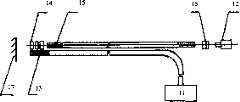
已有的一种光纤内窥镜的组成及工作原理如图1所示,包括光源11及CCD摄像机12、由非同配位排列的传光束13、物镜14、同配位排列的传像束15及目镜16组成的系统。为使整个视场照度均匀,传光束照明范围应大于视场角。物镜14设计为小孔径大视场,小孔径的设计要保证足够的景深,大视场的设计要保证近距离内能观察到尽可能宽的范围,前提是图像的畸变不影响使用的基本要求。由于纤维单丝直径的限制,目镜16的放大倍率不能太高,一般情况下不超过10倍,否则会影响观察效果。The composition and working principle of an existing fiber optic endoscope are shown in Figure 1, including a
上述光纤内窥镜的工作原理是:光源11发出的光会聚到传光束13一端,经传光束13传输到光纤内窥镜前端部照明被测物体17,被测物体17的图像由物镜14成像到传像束15的输入端面,通过传像束15再传至输出端面,用目镜16将它放大,人眼就可以直接观察或经CCD摄像机12接收后输入到系统附属的图像采集处理单元。The working principle of the above-mentioned fiber optic endoscope is: the light emitted by the
上述光纤内窥镜采用的传光束13和传像束15都是由许多根单纤维丝经不同方式排列而成,在其两端用粘胶剂或加热熔压后固定,端面经过研磨、磨光、涂保护膜后,便制成了两端固定、中间松散的纤维束了。The
用以传入外部照明光的纤维束叫传光束,因其主要的功能是作照明,因而单纤维丝的直径可以较粗(一般为15~30微米),且排列并不要求整齐,即所谓非同配位排列,就是组成传光束的各光纤在输入端和输出端的两端头截面上不存在一一对应的位置关系。The fiber bundle used to transmit external lighting light is called beam transmission. Because its main function is to illuminate, the diameter of the single fiber can be thicker (generally 15-30 microns), and the arrangement is not required to be neat, that is, the so-called Non-isocoordinated arrangement means that there is no one-to-one corresponding positional relationship between the cross-sections of the two ends of the input and output ends of the optical fibers that make up the beam transmission.
为了有效利用传光束的照明光,传光束的输出端必须尽可能接近被测物体,因此,传光束的输出端在传像束的输入端附近发出光照射到被测物体上,并且,传光束的输出端和传像束的输入端以一定的结构形式结合,结合部组成光纤内窥镜的前端部,这种结构形式称为传光束的照明方式。通常情况下,传光束的照明方式有以下几种:随机型21、半圆型22、同心圆型23、环型24、异型25、混合型26,如图2所示。所谓随机型21,就是传光束的输出端的单纤维丝和传像束输入端的单纤维丝以随机的方式密集排列在一起;所谓半圆型22,就是传光束的输出端的单纤维丝和传像束输入端的单纤维丝各占接合部的一半,并且各自紧密排列;所谓同心圆型23,就是传光束的输出端的单纤维丝构成一个圆环位于结合部中间,传像束输入端的单纤维丝一部分构成一个圆位于结合部的中心,其它部分构成一个圆环位于结合部的外侧,三部分各自紧密排列;所谓环型24,就是传光束的输出端的单纤维丝构成一个圆环位于结合部的外侧,传像束输入端的单纤维丝构成一个圆位于结合部的中心,两部分各自紧密排列;所谓异型25,就是传光束的输出端的单纤维丝和传像束输入端的单纤维丝隔行或隔列紧密排列;所谓混合型,就是综合具备两种或两种以上排列特点的排列方式,如图2所示,传光束的输出端的单纤维丝一部分位于结合部的中心紧密排列,其它部分和传像束输入端的单纤维丝采取近似异型25的方式紧密排列在一起。具体采用哪种照明方式可根据使用场合的要求确定,为了保证视场照明的均匀程度,可以采用同心圆型23、环型24等照明方式。例如,为了观察并获得微齿轮真实图像,由于微齿轮图像灰度和背景灰度相近,而且观察距离较近(物距为3mm),因此必须保证视场照明的均匀程度,因此采用同心圆型23、环型24的照明方式,实验证明,这种照明方式能够获得较好的观察效果。In order to effectively use the illumination light of the beam transmission, the output end of the transmission beam must be as close as possible to the object under test. Therefore, the output end of the transmission beam emits light near the input end of the image transmission beam to irradiate the object under test, and the transmission beam The output end of the fiber optic endoscope and the input end of the image beam are combined in a certain structural form, and the joint part forms the front end of the fiber optic endoscope. This structural form is called the illumination method of the beam transmission beam. Usually, there are the following types of lighting methods for beam transmission:
用来传递图像的纤维束称传像束,其主要功能是传递传光束照明下的被测物体图像,以便人眼直接观察或采集到计算机中保存处理,因而,已有内窥镜的传像束两端的单纤维丝必须排列整齐(例如,采用正方形排列或六角形蜂窝状排列),并且必须为同配位排列,即传光束的输入端和输出端在两端头截面上存在一一对应的位置关系。The fiber bundle used to transmit the image is called the image transmission beam. Its main function is to transmit the image of the measured object under the illumination of the transmission beam, so that the human eye can directly observe or collect it into the computer for storage and processing. Therefore, the existing endoscope image transmission The monofilaments at both ends of the beam must be arranged neatly (for example, in a square arrangement or a hexagonal honeycomb arrangement), and must be in the same coordination arrangement, that is, there is a one-to-one correspondence between the input end and the output end of the beam transmission beam on the cross-section of the two ends. location relationship.
已有光纤内窥镜的光纤传像束的设计是依据单纤维丝传光的基本原理:光线在单纤维丝内的传导方式,如图3所示,当光线31以θ角由空气投射到单纤维丝端面32时,由于空气折射率小于玻璃折射率(n0<n1),光线以θ’角折向单纤维丝内,并以φ角投射到核心层33(n1)与被覆层34(n2)的界面上,如果由空气投射到端面的入射角θ适当,则能使进入界面上的φ角大于临界角(φM),因此在界面上产生全反射,在单纤维丝任意弯曲的情况下,光线经成千上万次的全反射,最后仍以θ角度由单纤维丝的另一端面35射出。在没有断丝和暗丝的情况下,每根单纤维丝可以不失真的传递被测物体表面反射的光信息,从而构成了被测物体图像上的一个像元,对一根由几万根单纤维丝组成的光纤束来说,其输入端的所有像元将全部被传递到输出端,也就是传递了被测物体的一幅图像,这就是传像束传递图像的原理。上述光纤内窥镜的传像束由于采取同配位排列方式,因此,其输入端41和输出端42的像元存在一一对应的关系,如图4所示,传像束的输入端41的物体图像的像元A、B、C的位置与传像束的输出端42的物体图像的像元A’、B’、C’的位置为一一对应关系。The design of the optical fiber image transmission bundle of the existing fiber optic endoscope is based on the basic principle of single fiber light transmission: the transmission mode of light in the single fiber, as shown in Figure 3, when the light 31 is projected from the air to the At the end surface of the monofilament 32, since the refractive index of air is smaller than that of glass (n0 <n1 ), the light is bent into the monofilament at the angle θ', and projected to the core layer 33 (n1 ) and the coating layer at the angle φ 34(n2 ) on the interface, if the incident angle θ projected from the air to the end face is appropriate, the φ angle on the entering interface can be larger than the critical angle (φM ), so total reflection occurs on the interface, and the monofilament In the case of arbitrary bending, the light is totally reflected thousands of times, and finally exits from the other end surface 35 of the monofilament at an angle of θ. In the absence of broken wires and dark wires, each single fiber can transmit the light information reflected by the surface of the measured object without distortion, thus constituting a pixel on the image of the measured object. For an optical fiber bundle composed of fiber filaments, all the pixels at the input end will be transmitted to the output end, that is, an image of the object under test is transmitted, which is the principle of the image transmission beam to transmit images. Because the image beam of the above-mentioned fiber optic endoscope adopts the same coordination arrangement, there is a one-to-one correspondence between the pixels of its input end 41 and output end 42, as shown in Figure 4, the input end 41 of the image beam The positions of the pixels A, B, and C of the object image and the positions of the pixels A', B', and C' of the object image at the output end 42 of the image beam have a one-to-one correspondence.
为了增加传像的清晰度,传像束单位面积内的单纤维丝直径较细(一般为5~20微米)。每根单纤维丝构成被传递图像上的一个光点。在理想情况下,由物镜所成的图像,经传像束的一端不失真的以一定的分辨率传至另一端。光点越密,两端排列越整齐,它所传递的图像越清晰,每断丝一根,就因该单纤维丝不能传像而在被测物体图像上产尘一个黑点。从本质上讲,光纤内窥镜传递被测物体图像的质量主要取决于传像束的制作质量,影响因素包括单丝直径、两端的同配位排列程度、排列的紧密程度、断丝、音丝、界面交扰等。In order to increase the definition of the image transmission, the diameter of the monofilament in the unit area of the image transmission bundle is relatively small (generally 5-20 microns). Each monofilament constitutes a spot of light on the transmitted image. Under ideal conditions, the image formed by the objective lens is transmitted to the other end with a certain resolution through one end of the image beam without distortion. The denser the light spot is, the more orderly the two ends are arranged, the clearer the image it transmits. Every time a single fiber is broken, a black spot will be produced on the image of the object under test because the single fiber cannot transmit the image. In essence, the quality of the image of the object under test transmitted by the fiber optic endoscope mainly depends on the quality of the image transmission beam. The influencing factors include the diameter of the single filament, the degree of co-ordination arrangement at both ends, the tightness of the arrangement, broken wire, sound Wire, interface crosstalk, etc.
在孙磊,“传像束制造工艺的探讨”,《光纤与电缆及其应用技术》,1998年,第5期,第25-26页中描述了层叠法制造同配位排列的传像束中的叠片工艺。目前,国内外主要有酸溶法和层叠法两种传像束生产工艺,国内以后者为主。层叠法制造传像束,首先要拉制一定直径的连续单丝,然后将单丝排列成无间隙、无重叠的单片,再给单片上胶使单丝间相互固定,最后将单片按六角形排列规则层叠成束。层叠法的叠片工艺通过操作者肉眼观察莫尔条纹随两单片间夹角的变化而变化的情况,判定单片是否平行地、面对面地完成六角形排列。因此,层叠法生产工艺有很大局限性,首先是操作中对莫尔条纹精度的判断只能定性不能定量,人为因素的影响大;其次是单丝直径一般不能低于12μm,否则给生产带来很大困难。In Sun Lei, "Discussion on the Manufacturing Process of Image Transmission Beams", "Optical Fibers and Cables and Their Application Technology", 1998, No. 5, pp. 25-26, described the lamination method to manufacture image transmission beams with the same coordination arrangement The lamination process in . At present, there are mainly two image beam production processes at home and abroad, the acid solution method and the lamination method, and the latter is the main method in China. To manufacture the image beam by lamination method, it is first necessary to draw continuous monofilaments of a certain diameter, then arrange the monofilaments into a single piece without gaps and overlaps, then glue the single piece to fix the monofilaments to each other, and finally place the single piece According to the rules of hexagonal arrangement, they are stacked into bundles. In the lamination process of the lamination method, the operator observes the change of the moiré fringe with the change of the angle between the two single pieces with the naked eye, and determines whether the single pieces are parallel and face-to-face to complete the hexagonal arrangement. Therefore, the production process of the lamination method has great limitations. First, the judgment of the accuracy of Moiré fringes in the operation can only be qualitative but not quantitative, and the influence of human factors is large; secondly, the diameter of the monofilament generally cannot be lower than 12 μm, otherwise it will bring problems to the production. Come very difficult.
例如南京玻璃纤维研究设计院第三研究所采用层叠法工艺制造传像束,由于工艺本身的局限、生产设备的制造误差、人为因素的主观影响,因而不能在严格意义上完全保证传像束两端的单纤维丝排列整齐紧密和同配位排列,因此,观察到的图像实际上存在网格和部分象素错位现象。层叠法制造光纤传像束,还由于断丝、暗丝的影响,成品率较低,因而增加了生产成本和产品不合格率。For example, the Third Research Institute of Nanjing Glass Fiber Research and Design Institute adopts the lamination process to manufacture the image beam. Due to the limitations of the process itself, the manufacturing error of the production equipment, and the subjective influence of human factors, it is impossible to completely guarantee the two-dimensionality of the image beam in a strict sense. The monofilaments at the end are arranged neatly and tightly and are coordinatingly arranged, so the observed image actually has grid and some pixel misalignment. The lamination method to manufacture the optical fiber image transmission bundle is also due to the influence of broken wires and dark wires, and the yield is low, thus increasing the production cost and product failure rate.
发明内容Contents of the invention
本发明的目的是为克服已有技术的不足之处,提供一种用于图像传输系统的处理方法及可检测物体图像的光纤内窥镜,该处理方法可从被测物体所接收到的杂乱的图像信息中恢复、重构真实的图像。此外,这种用于图像传输系统的处理方法还在数据保密、网络安全、产品防伪等其它方面有特殊的应用价值。本发明设计的光纤内窥镜采用非同配位排列的光纤束作为传像束,可简化传像束的制作工艺,有效降低生产成本,且没有增加光纤内窥镜装置结构的复杂性。通过采用本发明方法的图像采集处理软件,可以恢复被测物体的真实图像,并能获取被测物体的精确二维尺寸信息,此外,通过图像平滑处理还能消除已有光纤内窥镜所成的被测物体图像的网格现象。The purpose of the present invention is to overcome the deficiencies of the prior art, to provide a processing method for an image transmission system and a fiber optic endoscope that can detect object images. Restoring and reconstructing the real image from the image information. In addition, this processing method for the image transmission system also has special application value in other aspects such as data security, network security, and product anti-counterfeiting. The optical fiber endoscope designed by the present invention adopts the fiber bundles arranged in non-isocoordination as the image transmission bundle, which can simplify the manufacturing process of the image transmission bundle, effectively reduce the production cost, and does not increase the complexity of the structure of the fiber optic endoscope device. By adopting the image acquisition and processing software of the method of the present invention, the real image of the measured object can be recovered, and the accurate two-dimensional size information of the measured object can be obtained. In addition, the image smoothing process can also eliminate the defects caused by the existing optical fiber endoscope. The grid phenomenon of the measured object image.
本发明提出的一种用于图像传输系统的图像处理方法,其特征在于,传输通道的输入输出两端面上采用非同配位排列的方式;可将被测物体从在该输出端的杂乱的图像信息中恢复、重构成为真实的图像;由标定及实测两部分构成,所说的标定方法包括以下步骤:An image processing method for an image transmission system proposed by the present invention is characterized in that the input and output ends of the transmission channel are arranged in a non-isocoordinated manner; The information is recovered and reconstructed into a real image; it consists of two parts: calibration and actual measurement. The calibration method includes the following steps:
(1)对图象传输系统作初始化处理;(1) Initialize the image transmission system;
(2)将标定所用的光照射传输通道的输入端使输入端相对光斑作匀速逐行扫描运动;(2) irradiating the input end of the transmission channel with the light used for calibration so that the input end performs a uniform progressive scanning motion relative to the light spot;
(3)实时获取光斑信息,判断有无光斑信息输入,如果有,进入第(4)步;如果没有,继续判断;(3) Obtain spot information in real time, judge whether there is spot information input, if yes, enter step (4); if not, continue to judge;
(4)对获得的像元灰度值大小进行判断,在每出现一个灰度极小值的情况时,记录下该像元的位置PIXB01(X1,Y1),根据扫描时间和匀速逐行扫描运动的速度可计算出相应的输入光斑所在的位置PIXA01(X0,Y0),然后用映射(4) Judging the gray value of the pixel obtained, and recording the position PIXB01(X1 , Y1 ) of the pixel every time there is a minimum gray value, according to the scanning time and constant speed The speed of the line scanning motion can calculate the position of the corresponding input spot PIXA01(X0 , Y0 ), and then use the mapping
F:(x,y)(u,v)来表示输入光斑位置和输出像元位置的一一对应关系,继续判断有无光斑信息输入,若有,返回步骤(4);若扫描下一行过程中仍然没有光斑信息的输入,进入步骤(5);F: (x, y)(u, v) to represent the one-to-one correspondence between the input spot position and the output pixel position, continue to judge whether there is spot information input, if yes, return to step (4); if scan the next line There is still no input of spot information in the process, enter step (5);
(5)结束扫描,生成与映射对应的标定函数,并保存得到的光斑所有像元图像信息;(5) End the scan, generate a calibration function corresponding to the mapping, and save the obtained image information of all pixels of the spot;
所说的实测方法包括以下步骤:Said measured method comprises the following steps:
(1)对图象传输系统作初始化处理;(1) Initialize the image transmission system;
(2)通过传输通道获取被测物体图像的杂乱信息;(2) Obtain the messy information of the image of the measured object through the transmission channel;
(3)确定实测得到的图像信息和标定得到的光斑所有像元图像信息的大小比例,按照该比例缩放实测得到的图像信息,并用标定函数变换实测得到的图像信息,产生新的图像信息;(3) Determine the size ratio of the image information obtained by actual measurement and the image information of all pixels of the light spot obtained by calibration, scale the image information obtained by actual measurement according to this ratio, and transform the image information obtained by actual measurement with a calibration function to generate new image information;
(4)按照该大小比例的倒数变换第(3)步得到的新的图像信息,并重构被测物体的真实图像;(4) Transform the new image information obtained in step (3) according to the reciprocal of the size ratio, and reconstruct the real image of the measured object;
(5)显示保存被测物体真实图像,并进行被测物体的图像二维尺寸计算。(5) Display and save the real image of the measured object, and calculate the two-dimensional size of the image of the measured object.
所说像元的位置、光斑的位置采用二维坐标值来表示。The position of the pixel and the position of the light spot are represented by two-dimensional coordinate values.
所说的映射的具体形式可采用二维矩阵方法、伪彩色图方法、四维数组方法或长数字方法等等可以表示位置一一对应关系的方法。The specific form of said mapping can be a two-dimensional matrix method, a pseudo-color image method, a four-dimensional array method or a long number method, etc., which can represent the one-to-one correspondence between positions.
所说的标定方法采用的光源,其发出的光可经聚焦成像后在图象传输系统的传输通道的输入端前方形成一个光斑,传入传输通道的输入端,并且光源形成的光斑发出的光进入一个传输通道的输入端时,光的范围大小应小于传输通道的截面大小。The light source used in the calibration method, the light emitted by it can form a spot in front of the input end of the transmission channel of the image transmission system after focusing and imaging, and enter the input end of the transmission channel, and the light emitted by the light spot formed by the light source When entering the input end of a transmission channel, the size of the light range should be smaller than the cross-sectional size of the transmission channel.
所说的标定方法采用的光源,其发出的光可耦合进入一根传光光纤,这根传光光纤输出的光在图象传输系统的传输通道的输入端前方形成一个光斑,传入传输通道的输入端,并且这根传光光纤形成的光斑发出的光进入一个传输通道的输入端时,光的范围大小应小于传输通道的截面大小。The light source used in the calibration method can be coupled into a light-transmitting optical fiber, and the light output by this light-transmitting optical fiber forms a light spot in front of the input end of the transmission channel of the image transmission system, and enters the transmission channel. When the light emitted by the light spot formed by this light-transmitting optical fiber enters the input end of a transmission channel, the size of the light range should be smaller than the cross-sectional size of the transmission channel.
本发明设计一种采用上述方法的光纤内窥镜,由传光部件和传像部件组成,该传光部件包括用于照明的光源、传递照明光用于提高被测物体照明光强和照明均匀程度的传光束以及将照明光耦合到该传光束的耦合透镜;该传像部件包括传像束、耦合被测物体的反射光到该传像束输入端的物镜、接收并放大传像束的输出端图像信息的目镜、CCD摄像机、用于采集处理图像信息的图像采集处理单元、以及用于显示被测物体图像信息的监视器,该图像采集处理单元包括计算机以及与该计算机的接口相连的图像采集卡;其特征在于,所说的传像束采用非同配位排列方式的光纤束,所说的计算机存储有用于从被测对象杂乱的图像信息中恢复、重构被测物体真实图像的标定模块及实测模块。The present invention designs a fiber optic endoscope adopting the above method, which is composed of a light transmission part and an image transmission part. The light transmission part includes a light source for illumination, and the transmission of illumination light is used to improve the illumination intensity and uniformity of the measured object. The beam of the degree and the coupling lens that couples the illumination light to the beam; the image component includes the image beam, the objective lens that couples the reflected light of the measured object to the input end of the image beam, and receives and amplifies the output of the image beam The eyepiece of the terminal image information, the CCD camera, the image acquisition and processing unit for collecting and processing the image information, and the monitor for displaying the image information of the measured object. Acquisition card; it is characterized in that, said image transmission beam adopts the optical fiber bundle of non-isocoordinated arrangement mode, and said computer stores are used for recovering from the messy image information of measured object, reconstruct the real image of measured object Calibration module and actual measurement module.
所说的CCD摄像机可为CCD面阵摄像机,用于将传像束的输出端传出的被测物体的光信息转换成为相应的电荷信息。The CCD camera can be a CCD area camera, which is used to convert the light information of the measured object transmitted from the output end of the image beam into corresponding charge information.
本发明的主要特点:Main features of the present invention:
本发明利用标定方法可确定图象传输系统的传输通道的输入输出两端的位置的一一对应关系,采用映射来表示,并生成与映射对应的标定函数存入图像采集处理单元;利用实测方法可获取被测物体杂乱的图像信息,借助标定函数,可以确定杂乱的图像信息中的每一个像元的正确位置,从而恢复、重构被测物体的真实图像。The present invention utilizes the calibration method to determine the one-to-one correspondence between the positions of the input and output ends of the transmission channel of the image transmission system, uses mapping to represent, and generates a calibration function corresponding to the mapping and stores it in the image acquisition and processing unit; using the actual measurement method, it can Obtain the messy image information of the measured object, and use the calibration function to determine the correct position of each pixel in the messy image information, thereby restoring and reconstructing the real image of the measured object.
本发明设计的光纤内窥镜在已有光纤内窥镜的基础上,为减少生产工艺的复杂程度和有效降低生产成本,用非同配位排列的传像束替代同配位排列的传像束,用于获取被测物体的图像信息,由于光纤束是非同配位排列的,因而在光纤束输出端得到的图像信息也是杂乱的,该杂乱的图像信息被—CCD摄像机所接收,并送入到计算机中保存,借助本发明提供的用于图像传输系统的处理方法,对本发明的光纤内窥镜进行标定后,从而得到标定函数,可以确定杂乱的图像信息中的每一个像元的正确位置,并恢复被测物体的真实图像。The optical fiber endoscope designed by the present invention is based on the existing optical fiber endoscope, in order to reduce the complexity of the production process and effectively reduce the production cost, the image transmission beam of the same coordination arrangement is replaced by the image transmission beam of the same coordination arrangement. bundle, used to obtain the image information of the measured object, because the fiber bundle is non-isocoordinated, the image information obtained at the output end of the fiber bundle is also messy, and the messy image information is received by the CCD camera and sent to It is stored in the computer, and with the help of the processing method for the image transmission system provided by the present invention, after the fiber optic endoscope of the present invention is calibrated, the calibration function is obtained, and the correctness of each pixel in the messy image information can be determined. position, and recover the real image of the measured object.
附图说明Description of drawings
图1为已有光纤内窥镜的光学系统组成示意图,Figure 1 is a schematic diagram of the composition of the optical system of an existing fiber optic endoscope,
图2为已有光纤内窥镜的传光束照明方式示意图,Fig. 2 is a schematic diagram of the light beam illumination mode of the existing fiber optic endoscope,
图3为单纤维丝传光的基本原理示意图,Figure 3 is a schematic diagram of the basic principle of single fiber light transmission,
图4为已有光纤内窥镜的传像束的像元输入输出对应关系示意图,Fig. 4 is a schematic diagram of the corresponding relationship between pixel input and output of the image beam of the existing fiber optic endoscope,
图5为本发明的装置基本结构示意图,Fig. 5 is a schematic diagram of the basic structure of the device of the present invention,
图6为本发明的实施例的传像束的像元输入输出对应关系示意图,Fig. 6 is a schematic diagram of the corresponding relationship between input and output of pixels of an image transmission beam according to an embodiment of the present invention,
图7为本发明的实施例的标定装置原理示意图,Fig. 7 is a schematic diagram of the principle of the calibration device of the embodiment of the present invention,
图8为本发明的实施例的图像处理软件流程图。FIG. 8 is a flowchart of image processing software according to an embodiment of the present invention.
具体实施方式Detailed ways
本发明提出的用于图像传输系统的图像处理方法及采用该方法设计的光纤内窥镜结合各附图及实施例详细说明如下。The image processing method used in the image transmission system proposed by the present invention and the fiber optic endoscope designed by this method are described in detail below in conjunction with the drawings and embodiments.
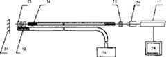
采用本发明的图像处理方法设计的光纤内窥镜装置的基本结构如图5所示,包括光源51、传光束52、物镜53、传像束54、目镜55、CCD摄像机56、图像采集处理单元57(即安装有图像采集卡的计算机)、监视器58。本发明是在已有内窥镜装置结构的基础上,用非同配位排列的传像束54替代同配位排列的传像束,因此,所获取的被测物体59图像信息是杂乱的,不能通过目镜55直接观察图像,也不能在监视器58直接显示真实图像。因此,本发明的装置必须包括CCD摄像机56、图像采集处理单元57、监视器58。此外,本发明的图像采集处理单元存储有图像采集处理软件,以便对被测物体59杂乱的图像信息进行采集处理并显示。其中还包括一个通过对采用的传像束进行标定后得到的标定函数,并用于恢复被测物体59真实的图像信息。Adopt the basic structure of the optical fiber endoscope device of image processing method design of the present invention as shown in Figure 5, comprise
本发明的传像束的像元输入输出对应关系原理如图6所示,由于光纤束采用非同配位排列,由图6可见,物体图像在输入端61的像元A、B、C的位置和在输出端62的像元A’、B’、C’的位置在两个端面上没有一一对应的关系,也即如果在两个端面中心处分别建立极坐标系,以(r1,θ1),(r2,θ2)来分别表征同一个像元在输入61输出62两个端面上的位置,r1=r2,θ1=θ2对任一个像元不能总成立,而对于光纤束理想的同配位排列,必然可以在两个端面中心处分别建立这样的极坐标系,使得r1=r2,θ1=θ2对任一个像元能总成立。此外,在非同配位排列的情况下,由于单纤维丝在端面处的排列是任意的,因此,两根光纤束的非同配位排列情况也是互不相同的,也就是说,非同配位排列没有重复性。The principle of the pixel input-output correspondence relationship of the image transmission beam of the present invention is as shown in Figure 6. Since the optical fiber bundle adopts non-isocoordination arrangement, it can be seen from Figure 6 that the object image is at the pixel A, B, and C of the
由于本发明的传像束是非同配位排列的,并且没有重复性,因此本发明的每一个实施例在第一次使用前需要进行准确的标定,从而得到该实施例的特定的标定函数并将其存储到实施例的图像采集处理单元中,才能恢复该实施例所观察物体的真实图像。经过标定后的本发明的实施例,由于其传像束两端用粘胶剂或加热熔压后固定了每一根单纤维丝的位置,所以在使用时不需要再次进行标定,只需要使用本发明的标定函数,就可在计算机屏幕上显示被测物体的真实图像,但是,人眼不能通过目镜直接观察图像。因此,一旦标定后,无需再次进行标定。Since the image beam of the present invention is non-isocoordinated and has no repeatability, each embodiment of the present invention needs to be accurately calibrated before the first use, so as to obtain the specific calibration function of this embodiment and Only by storing it in the image acquisition and processing unit of the embodiment can the real image of the object observed in the embodiment be recovered. In the embodiment of the present invention after calibration, the position of each monofilament is fixed after the two ends of the image transmission beam are fixed with adhesive or heating and melting, so there is no need to calibrate again when using it, only need to use The calibration function of the present invention can display the real image of the measured object on the computer screen, but human eyes cannot directly observe the image through the eyepiece. Therefore, once calibrated, there is no need to calibrate again.
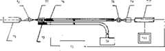
用于本发明各个实施例的标定装置的组成及原理如图7所示,标定装置包括标定光源71、聚焦透镜72、位移工作台73。标定时,本发明的实施例本身所属的光源74、传光束75停止工作,标定装置将光信息输入到该实施例的传像束76输入端。标定光源71发出的光经聚焦透镜72聚焦,在传像束76的物镜77的最佳物距处形成一个光斑,该光斑由物镜77所成的像光斑直径略小于传像束76的单纤维丝直径。该光斑经物镜77耦合入传像束76的一根单纤维丝的输入端,经传像束76传递到该单纤维丝的输出端,由目镜78放大并为CCD摄像机79靶面所敏感,并送入到图像采集处理单元710中并在监视器711上显示为一个像元。位移工作台73控制传像束76前端进行X或Y方向的步进运动,从而可以实现传像束76的前端做相对于光斑的匀速逐行扫描运动,并且,每相对移动一步,光斑由物镜77所成的像光斑相对传像束76输入端面的移动距离应该小于传像束76输入端面两根单纤维丝的最小中心距,否则,应调整位移工作台73的步长参数。位移工作台73也可以由其他可以实现相同功能的装置替代。在位移工作台73的控制下,物镜77和传像束76一起相对该光斑运动,控制位移工作台73的运动参数,就能实现该光斑对传像束76的输入端进行匀速逐行扫描,并得到每一根单纤维丝的输入输出端的位置对应关系,用映射F:(x,y)(u,v)描述这个位置对应关系,根据这个映射就可以采用程序代码描述所标定的实施例的物像的像元位置对应关系,该程序代码就是实施例的标定函数,将相应的软件代码存储到该实施例的图像采集处理单元710,就能检测被测物体的真实图像。依据光纤耦合理论,在耦合区的中心,耦合效率最高,因此,在匀速逐行扫描时,光斑每扫描过一个单纤维丝端面,扫描到该单纤维丝输入端面的中心处时该单纤维丝输出的光强为最大值,图像采集处理单元710就得到一个灰度最小值,这时得到的位置对应关系才是真实的单纤维丝的输入输出端的位置对应关系。因此,图像采集处理单元710必须对扫描时获得的像元灰度值大小进行判断,并计算出现极小值的情况时的位置对应关系。同样,在同一最佳物距下实测被测物体时,可以把物体上的每个点(该点的直径与光斑直径相同)都看成是一个个相同大小的光斑,分别耦合入传像束76的所有单纤维丝的输入端,经过传递放大,采集到图像采集处理单元710中,直接显示为杂乱的图像信息,经图像采集处理710单元经标定得到的标定函数进行处理后,恢复为真实的图像信息;在不同物距下实测被测物体时,考虑该实施例光学系统本身的放大倍率的影响,应先确定图像采集处理单元710接收到的杂乱的图像信息和标定时接收到的光斑所有像元图像信息的大小比例(该大小指的是未经处理在监视器711上直接显示杂乱的图像信息时,X、Y方向各有多少像素,例如100×100),并按照该大小比例将实测时接受到的杂乱的图象信息在不改变像素间相互位置关系的情况下缩放,然后用标定得到的标定函数进行处理得到新的图像信息,并按照上述大小比例的倒数将新的图象信息缩放,缩放后的图像信息即为被测物体的真实的图像信息,输出到监视器711显示即为被测物体的真实图像。The composition and principle of the calibration device used in various embodiments of the present invention are shown in FIG. 7 . The calibration device includes a
本发明的标定装置所用的光源发出的光也可以不通过上述聚焦透镜形成光斑的方法,而通过一个耦合透镜耦合进入一根传光光纤中,这根传光光纤的输出端输出一个光斑,并经光纤内窥镜的物镜耦合入传像束的一根单纤维丝的输入端,并且该光斑发出的光进入一个单纤维丝的输入端时,光的范围大小应小于传输通道的截面大小。The light emitted by the light source used in the calibration device of the present invention can also be coupled into a light-transmitting optical fiber through a coupling lens without passing through the above-mentioned focusing lens to form a light spot, and the output end of this light-transmitting optical fiber outputs a light spot, and When the objective lens of the fiber optic endoscope is coupled into the input end of a single fiber of the image beam, and the light emitted by the spot enters the input end of a single fiber, the size of the light range should be smaller than the cross-sectional size of the transmission channel.
采用本发明方法的光纤内窥镜中的图像处理软件流程实施例如图10所示。该图像处理软件主要有两个的模块:标定模块和实测模块。标定模块用于本发明的实施例第一次使用前,本发明采用映射F:(x,y)(u,v)来表示光斑位置和像元位置的一一对应关系,像元位置、光斑位置采用二维坐标值(x,y),(u,v)来表示,映射的具体形式可采用二维矩阵方法、伪彩色图方法、四维数组方法或长数字方法等等可以表示位置一一对应关系的方法。其中,二维矩阵方法,即构造一个二维矩阵,其中某个元素的行数、列数分别表示某个像元的位置,该元素的值表示该像元对应的光斑的位置,该元素的值的长度为传像束横截面方向最大单纤维丝根数m的的2倍,其中,前m位和后m位分别表示光斑的某个二维坐标值中的一个坐标;反之,某个元素的行数、列数和该元素的值所表示的位置意义也可以相互调换。伪彩色图方法,即构造一幅伪彩色图,该伪彩色图上的某个像元的横、纵坐标分别表示某个像元的位置,该伪彩色图的这个像元的RGB值中的某两个分别表示该像元对应的光斑的位置,RGB的另一个值可以任意指定一个合法值;反之,某个像元的横、纵坐标和该像元的RGB值所表示的位置意义也可以相互调换。四维数组方法,即构造许多个四维数组,每个数组按同样的先后顺序存放像元的位置、相应的光斑位置,所有的四维数组按照像元排列的一定顺序进行先后排队;反之,每个数组存放像元的位置、相应的光斑位置的先后顺序也可以相互调换。长数字方法,即构造许多个长数字,所有的长数字按照像元排列的一定顺序进行先后排队,每个长数字的长度为传像束横截面方向最大单纤维丝根数m的4倍,其中,前2m位和后2m位分别表示像元位置和相应的光斑位置;反之,前2m位和后2m位所表示的位置意义也可以相互调换。在本实施例中,采用二维矩阵方法表示这种对应关系。实测模块用于本发明的实施例实际检测时。具体处理步骤分别叙述如下:An embodiment of the image processing software flow in the fiber optic endoscope using the method of the present invention is shown in FIG. 10 . The image processing software mainly has two modules: a calibration module and an actual measurement module. Before the calibration module is used in the embodiment of the present invention for the first time, the present invention uses the mapping F: (x, y) (u, v) to represent the one-to-one correspondence between the spot position and the pixel position, the pixel position, The spot position is represented by two-dimensional coordinate values (x, y), (u, v), and the specific form of mapping can be represented by two-dimensional matrix method, pseudo-color map method, four-dimensional array method or long number method, etc. One-to-one relationship method. Among them, the two-dimensional matrix method is to construct a two-dimensional matrix, in which the number of rows and columns of an element respectively represent the position of a certain pixel, the value of this element represents the position of the spot corresponding to this pixel, and the number of the element The length of the value is 2 times of the maximum single fiber root number m in the direction of the cross-section of the image beam, where the first m bits and the last m bits respectively represent a coordinate in a certain two-dimensional coordinate value of the spot; otherwise, a certain The number of rows and columns of an element and the meaning of the position represented by the value of the element can also be interchanged. The pseudo-color map method is to construct a pseudo-color map. The horizontal and vertical coordinates of a certain pixel on the pseudo-color map represent the position of a certain pixel respectively, and the RGB value of the pixel in the pseudo-color map is Some two represent the position of the light spot corresponding to the pixel, and another value of RGB can specify a legal value arbitrarily; conversely, the meaning of the position represented by the horizontal and vertical coordinates of a certain pixel and the RGB value of the pixel is also can be interchanged. The four-dimensional array method is to construct many four-dimensional arrays, and each array stores the position of the pixel and the corresponding light spot position in the same order, and all four-dimensional arrays are lined up in a certain order according to the arrangement of the pixels; on the contrary, each array The order of storing the position of the pixel and the position of the corresponding spot can also be exchanged. The long number method is to construct many long numbers, and all the long numbers are lined up in a certain order according to the pixel arrangement, and the length of each long number is 4 times of the maximum single fiber root number m in the cross-sectional direction of the image beam, Among them, the first 2m bits and the last 2m bits indicate the position of the pixel and the corresponding light spot position respectively; conversely, the position meanings indicated by the first 2m bits and the last 2m bits can also be interchanged. In this embodiment, a two-dimensional matrix method is used to represent this correspondence. The actual measurement module is used for the actual detection of the embodiment of the present invention. The specific processing steps are described as follows:
(一)标定模块(1) Calibration module
1、对图像采集卡作初始化处理;1. Initialize the image acquisition card;
2、用图像采集卡实时从CCD摄像机获取光斑信息,判断有无光斑信息输入,如果有,进入第3步;如果没有,继续判断;2. Use the image acquisition card to obtain spot information from the CCD camera in real time, and judge whether there is spot information input. If yes, go to step 3; if not, continue to judge;
3、对获得的像元灰度值大小进行判断,在每出现一个灰度极小值的情况时,记录下该像元的位置PIXB01(X1,Y1),根据扫描时间和匀速逐行扫描运动的速度可计算出相应的扫描光斑所在的位置PIXA01(X0,Y0),然后用矩阵MAT记录描述这种一一对应的关系,依据PIXB的坐标X1,Y1分别确定了某个元素位于矩阵第X1行,第Y1列,矩阵元素MATX1Y1的值VALPIX01由PIXA01(X0,Y0)确定,VALPIX01=X0×m+Y0(设传像束横截面方向最大单纤维丝根数为m);3. Judging the gray value of the pixel obtained, and recording the position PIXB01(X1 , Y1 ) of the pixel every time a minimum gray value occurs, and proceed line by line according to the scanning time and constant speed The speed of the scanning movement can calculate the position of the corresponding scanning spot PIXA01 (X0 , Y0 ), and then use the matrix MAT record to describe this one-to-one correspondence relationship. According to the coordinates X1 and Y1 of PIXB, a certain The element is located in the X1 row of the matrix, the Y1 column, the value VALPIX01 of the matrix element MATX1Y1 is determined by PIXA01(X0 , Y0 ), VALPIX01=X0 ×m+Y0 (assuming that the cross-sectional direction of the image beam is the largest The number of single fibers is m);
4、继续判断有无光斑信息输入,若有,返回步骤三;若扫描下一行过程中仍然没有光斑信息的输入,进入步骤5;4. Continue to judge whether there is light spot information input, if yes, return to step 3; if there is still no light spot information input during scanning the next line, go to step 5;
5、结束扫描,生成标定函数,并保存得到的光斑所有像元图像信息。5. End the scan, generate a calibration function, and save the obtained image information of all pixels of the spot.
(二)实测模块(2) Measured module
1、对图像采集卡作初始化处理;1. Initialize the image acquisition card;
2、用图像采集卡从CCD摄像机获取被测物体杂乱的图像信息,并显示;2. Use the image acquisition card to obtain the messy image information of the measured object from the CCD camera, and display it;
3、确定实测得到的图像信息和标定得到的光斑所有像元图像信息的大小比例,按照该比例缩放实测得到的图像信息,并用标定函数变换实测得到的图像信息,产生新的图像信息;3. Determine the size ratio of the measured image information and the calibrated spot image information of all pixels, scale the measured image information according to the ratio, and use the calibration function to transform the measured image information to generate new image information;
4、按照该大小比例的倒数变换第3步得到的新的图像信息,并重构被测物体的真实图像;4. Transform the new image information obtained in step 3 according to the reciprocal of the size ratio, and reconstruct the real image of the measured object;
5、对重构后的真实图像进行图像平滑处理,以便消除网格现象;5. Perform image smoothing processing on the reconstructed real image in order to eliminate the grid phenomenon;
6、显示保存被测物体真实图像,并进行被测物体的二维尺寸计算。6. Display and save the real image of the measured object, and calculate the two-dimensional size of the measured object.
Claims (10)
Priority Applications (1)
| Application Number | Priority Date | Filing Date | Title |
|---|---|---|---|
| CNB021165122ACN1156795C (en) | 2002-03-27 | 2002-03-27 | Image processing method for image transmission system and its optical fibre endoscope |
Applications Claiming Priority (1)
| Application Number | Priority Date | Filing Date | Title |
|---|---|---|---|
| CNB021165122ACN1156795C (en) | 2002-03-27 | 2002-03-27 | Image processing method for image transmission system and its optical fibre endoscope |
Publications (2)
| Publication Number | Publication Date |
|---|---|
| CN1376443A CN1376443A (en) | 2002-10-30 |
| CN1156795Ctrue CN1156795C (en) | 2004-07-07 |
Family
ID=4744133
Family Applications (1)
| Application Number | Title | Priority Date | Filing Date |
|---|---|---|---|
| CNB021165122AExpired - Fee RelatedCN1156795C (en) | 2002-03-27 | 2002-03-27 | Image processing method for image transmission system and its optical fibre endoscope |
Country Status (1)
| Country | Link |
|---|---|
| CN (1) | CN1156795C (en) |
Families Citing this family (39)
| Publication number | Priority date | Publication date | Assignee | Title |
|---|---|---|---|---|
| CN1306309C (en)* | 2003-04-28 | 2007-03-21 | 南开大学 | Optic fiber digital microendoscope device for canalis radicis dentis |
| CN1313879C (en)* | 2003-08-22 | 2007-05-02 | 中国科学院上海光学精密机械研究所 | Adjustable camera lighting device |
| CN100367281C (en)* | 2005-06-01 | 2008-02-06 | 中国人民解放军国防科学技术大学 | Synchronous capture method of pulsed laser spot by software |
| CN100468442C (en)* | 2006-02-05 | 2009-03-11 | 原相科技股份有限公司 | Method for identifying multiple object images without recording full images |
| CN100468446C (en)* | 2006-02-05 | 2009-03-11 | 原相科技股份有限公司 | Dynamic image identification method and system using same |
| JP2008067780A (en)* | 2006-09-12 | 2008-03-27 | Olympus Medical Systems Corp | Endoscope device |
| US8324562B2 (en) | 2007-07-20 | 2012-12-04 | Koninklijke Philips Electronics N.V. | Fiber scanning system having a magnet attached to the fiber at a position before or after an electrical coil with improved tip positioning |
| CN101593292B (en)* | 2009-05-07 | 2012-01-04 | 长沙融威电子科技有限公司 | Anti-counterfeiting method and anti-counterfeiting device for separating and counting non-touch paper currency or tickets |
| US9706903B2 (en) | 2009-06-18 | 2017-07-18 | Endochoice, Inc. | Multiple viewing elements endoscope system with modular imaging units |
| US9901244B2 (en) | 2009-06-18 | 2018-02-27 | Endochoice, Inc. | Circuit board assembly of a multiple viewing elements endoscope |
| US9713417B2 (en) | 2009-06-18 | 2017-07-25 | Endochoice, Inc. | Image capture assembly for use in a multi-viewing elements endoscope |
| US10165929B2 (en) | 2009-06-18 | 2019-01-01 | Endochoice, Inc. | Compact multi-viewing element endoscope system |
| US9492063B2 (en) | 2009-06-18 | 2016-11-15 | Endochoice Innovation Center Ltd. | Multi-viewing element endoscope |
| US11547275B2 (en) | 2009-06-18 | 2023-01-10 | Endochoice, Inc. | Compact multi-viewing element endoscope system |
| WO2010146587A1 (en) | 2009-06-18 | 2010-12-23 | Peer Medical Ltd. | Multi-camera endoscope |
| US9872609B2 (en) | 2009-06-18 | 2018-01-23 | Endochoice Innovation Center Ltd. | Multi-camera endoscope |
| US11278190B2 (en) | 2009-06-18 | 2022-03-22 | Endochoice, Inc. | Multi-viewing element endoscope |
| US12137873B2 (en) | 2009-06-18 | 2024-11-12 | Endochoice, Inc. | Compact multi-viewing element endoscope system |
| US9560953B2 (en) | 2010-09-20 | 2017-02-07 | Endochoice, Inc. | Operational interface in a multi-viewing element endoscope |
| EP2618718B1 (en) | 2010-09-20 | 2020-04-15 | EndoChoice Innovation Center Ltd. | Multi-camera endoscope having fluid channels |
| CN103403605A (en) | 2010-10-28 | 2013-11-20 | 恩多巧爱思创新中心有限公司 | Optical systems for multi-sensor endoscopes |
| US12204087B2 (en) | 2010-10-28 | 2025-01-21 | Endochoice, Inc. | Optical systems for multi-sensor endoscopes |
| US9320419B2 (en) | 2010-12-09 | 2016-04-26 | Endochoice Innovation Center Ltd. | Fluid channeling component of a multi-camera endoscope |
| CN107361721B (en) | 2010-12-09 | 2019-06-18 | 恩多巧爱思创新中心有限公司 | Flexible electronic circuit boards for multi-camera endoscopes |
| US11889986B2 (en) | 2010-12-09 | 2024-02-06 | Endochoice, Inc. | Flexible electronic circuit board for a multi-camera endoscope |
| EP2672878B1 (en) | 2011-02-07 | 2017-11-22 | Endochoice Innovation Center Ltd. | Multi-element cover for a multi-camera endoscope |
| CA2798716A1 (en) | 2011-12-13 | 2013-06-13 | Peermedical Ltd. | Removable tip endoscope |
| US9560954B2 (en) | 2012-07-24 | 2017-02-07 | Endochoice, Inc. | Connector for use with endoscope |
| CN103006168A (en)* | 2012-12-29 | 2013-04-03 | 上海乾衡生物科技有限公司 | Rapid cluster optical fiber imaging device |
| US9986899B2 (en) | 2013-03-28 | 2018-06-05 | Endochoice, Inc. | Manifold for a multiple viewing elements endoscope |
| US9993142B2 (en) | 2013-03-28 | 2018-06-12 | Endochoice, Inc. | Fluid distribution device for a multiple viewing elements endoscope |
| US10499794B2 (en) | 2013-05-09 | 2019-12-10 | Endochoice, Inc. | Operational interface in a multi-viewing element endoscope |
| CN103815863A (en)* | 2014-01-28 | 2014-05-28 | 河南科技大学 | Endoscope with swingable head end |
| CN105181149B (en)* | 2014-06-20 | 2018-08-21 | 国家电网公司 | A kind of portable all insulation pressure resistance infrared measurement of temperature endoscope |
| CN105716627B (en)* | 2016-02-05 | 2019-06-18 | 中国科学院国家空间科学中心 | A method for arranging uniformly distributed interference baselines of concentric circles for CCD calibration |
| CN110231020A (en)* | 2018-03-05 | 2019-09-13 | 深圳先进技术研究院 | Ripple sensor, ripple method for reconstructing and its application |
| CN110686602B (en)* | 2019-11-06 | 2025-03-28 | 中国工程物理研究院总体工程研究所 | Displacement testing system and displacement testing method |
| CN110823920A (en)* | 2019-11-07 | 2020-02-21 | 深圳市智能机器人研究院 | Device, system and method for collecting surface defects of inner hole side wall |
| CN117257214A (en)* | 2022-06-13 | 2023-12-22 | 深圳开立生物医疗科技股份有限公司 | Light guide device, lighting assembly and endoscope system |
- 2002
- 2002-03-27CNCNB021165122Apatent/CN1156795C/ennot_activeExpired - Fee Related
Also Published As
| Publication number | Publication date |
|---|---|
| CN1376443A (en) | 2002-10-30 |
Similar Documents
| Publication | Publication Date | Title |
|---|---|---|
| CN1156795C (en) | Image processing method for image transmission system and its optical fibre endoscope | |
| CN1207601C (en) | Confocal point microscope and height measuring method using this | |
| CN1821732A (en) | Method and device for real-time correcting infrared measuring temperature | |
| CN105391954B (en) | A kind of image-scanning system and image scanning module | |
| CN114923659B (en) | Flow field multi-section schlieren synchronous display system and method | |
| CN208044186U (en) | Lighting device, pathological section imaging device based on white light linear light source and scanning system | |
| CN106859579A (en) | A kind of fibre bundle confocal fluorescent endoscopic imaging method and device based on sub-pix | |
| CN109078858A (en) | High-precision A ngel type lobster eye optical fiber detector, detection method and sorting system | |
| CN102540638A (en) | Detection device for focal position and detection method thereof | |
| CN104168430A (en) | TDI CCD focal plane coding super-resolution imaging device and method | |
| CN111442908A (en) | Apparatus and method for detecting visible light transmittance and uniformity of optical fiber imaging element | |
| CN110794575A (en) | Bionic compound eye space detection and positioning system based on light energy information | |
| CN208876461U (en) | EO-1 hyperion endoscopic imaging system based on image transmission optical fibre | |
| CN106908942A (en) | The parallel microscopic imaging apparatus of high-resolution based on microlens array | |
| CN1209653C (en) | Three-dimensional profile measuring method and equipment with optical fiber panel and confocal microscope | |
| CN114240755B (en) | An image super-resolution reconstruction method based on fiber bundle combined with micro-scanning technology | |
| CN116359944A (en) | A system and method for surface scanning time-of-flight three-dimensional imaging based on streak camera | |
| CN117008245A (en) | Bionic compound eye system based on optical fiber image transmission beam | |
| CN2784875Y (en) | Novel micro three-dimensional topography measurer based on fiber-optic image bundles | |
| JPH0868721A (en) | Optical system focus evaluation method, adjustment method, focus evaluation device, adjustment device, and chart device | |
| CN111103062B (en) | A device and method for two-dimensional imaging based on single photon counting | |
| CN110989074B (en) | Imaging device based on optical fiber array | |
| CN110575142A (en) | A single-spectrometer multi-beam optical coherence tomography imager | |
| CN201173768Y (en) | Non-contact measurement device for measuring motion state red and hot metal outer diameter and size defect | |
| CN116499398B (en) | Apparatus and method for roughness sensor, roughness grade evaluation and three-dimensional evaluation |
Legal Events
| Date | Code | Title | Description |
|---|---|---|---|
| C10 | Entry into substantive examination | ||
| SE01 | Entry into force of request for substantive examination | ||
| C06 | Publication | ||
| PB01 | Publication | ||
| C10 | Entry into substantive examination | ||
| SE01 | Entry into force of request for substantive examination | ||
| C14 | Grant of patent or utility model | ||
| GR01 | Patent grant | ||
| C19 | Lapse of patent right due to non-payment of the annual fee | ||
| CF01 | Termination of patent right due to non-payment of annual fee |