CN115673545A - Semiconductor laser welding device - Google Patents
Semiconductor laser welding deviceDownload PDFInfo
- Publication number
- CN115673545A CN115673545ACN202211422947.2ACN202211422947ACN115673545ACN 115673545 ACN115673545 ACN 115673545ACN 202211422947 ACN202211422947 ACN 202211422947ACN 115673545 ACN115673545 ACN 115673545A
- Authority
- CN
- China
- Prior art keywords
- lens
- semiconductor laser
- laser welding
- output
- output beam
- Prior art date
- Legal status (The legal status is an assumption and is not a legal conclusion. Google has not performed a legal analysis and makes no representation as to the accuracy of the status listed.)
- Pending
Links
Images


Landscapes
- Laser Beam Processing (AREA)
Abstract
Description
Translated fromChinese技术领域technical field
本发明涉及半导体激光器领域,尤其涉及一种应用于激光手持焊接技术的半导体激光器焊接装置。The invention relates to the field of semiconductor lasers, in particular to a semiconductor laser welding device applied to laser hand-held welding technology.
背景技术Background technique
激光焊接是利用高能量密度的激光束作为热源的一种高效精密焊接方法,相对于传统的焊接技术,激光焊接可以实现极大的焊接效率和精度,可以满足于多种材质、金属的焊接需求,其功率和能量释放快,可以提高工作效率。目前激光焊接技术广泛被应运在汽车、轮船、飞机、高铁等高精制造领域,给人们的生活质量带来了重大提升,更是带领家电行业进入了精工时代。Laser welding is an efficient and precise welding method that uses a high-energy-density laser beam as a heat source. Compared with traditional welding techniques, laser welding can achieve great welding efficiency and precision, and can meet the welding needs of various materials and metals. , its power and energy are released quickly, which can improve work efficiency. At present, laser welding technology is widely used in high-precision manufacturing fields such as automobiles, ships, aircraft, and high-speed rail, which has brought significant improvements to people's quality of life and led the home appliance industry into the era of precision engineering.
手持式激光焊接相对于传统的焊接方式,具备耗材少、设备部署和维护成本低、性价比高、节约成本以及焊接速度快的特点,目前激光手持焊接绝大多数采用500-2000W的光纤激光器,针对不厚于3mm的不锈钢、铝合金、碳钢焊接,已开始逐渐替代传统的氩弧焊、二保焊。Compared with traditional welding methods, handheld laser welding has the characteristics of less consumables, low equipment deployment and maintenance costs, high cost performance, cost saving and fast welding speed. At present, most of the laser handheld welding uses 500-2000W fiber lasers. The welding of stainless steel, aluminum alloy and carbon steel not thicker than 3mm has begun to gradually replace the traditional argon arc welding and secondary welding.
以1000W光纤激光手持焊接光路设计为例,常采用50μm的光纤输出,经有效焦距40mm透镜准直后,再由有效焦距150mm透镜聚焦,焦点处光斑功率密度达3×10⁶W/cm2。光纤激光器出光为高亮度的高斯光束,由于亮度过高,易造成焊接熔池飞溅、焊穿较薄的目标加工板材,故常采用填丝焊接方法。Taking the design of the 1000W fiber laser handheld welding optical path as an example, a 50μm fiber output is often used. After being collimated by a lens with an effective focal length of 40mm, it is then focused by a lens with an effective focal length of 150mm. The power density of the spot at the focal point reaches 3×10⁶ W/cm2 . The fiber laser emits high-brightness Gaussian beams. Due to the high brightness, it is easy to cause spattering of the welding pool and welding through thinner target processing plates. Therefore, the wire-fill welding method is often used.
现有手持式激光焊接技术路线采用光纤激光光源,通过石英端帽出光后,通过一准直透镜准直,一次经过振镜、聚焦透镜、窗口镜后,聚焦于目标焊接工件表面,融化焊接材料,冷却后达到焊接目的,有如下缺点:光纤激光的激光功率密度过高,对透镜镀膜损伤阈值要求高;光纤激光器在焊接焦点处为高斯光斑,中心能量密度过高,极易造成飞溅,并且容易焊穿较薄的板材;光纤激光出光原理是采用915或976nm半导体激光泵浦带谐振腔结构的有源光纤,产生高亮度的波长在1064-1080nm的光纤激光,其光电效率为30%-35%左右,相对半导体激光器效率较低,能耗大;光纤激光器由于效率低,其发热量大,对散热要求高,无法长时间连续工作;光纤激光器相对半导体激光器结构更加复杂,成本更高。The existing hand-held laser welding technology route uses a fiber laser light source. After the light is emitted through the quartz end cap, it is collimated by a collimating lens. After passing through the galvanometer, focusing lens, and window mirror once, it focuses on the surface of the target welding workpiece and melts the welding material. , to achieve the purpose of welding after cooling, there are the following disadvantages: the laser power density of the fiber laser is too high, which requires high damage threshold of the lens coating; It is easy to weld through thinner plates; the principle of fiber laser light output is to use 915 or 976nm semiconductor laser to pump an active fiber with a resonant cavity structure to produce high-brightness fiber laser with a wavelength of 1064-1080nm, and its photoelectric efficiency is 30%- About 35%, compared with semiconductor lasers, the efficiency is low and energy consumption is large; fiber lasers have high heat dissipation requirements due to low efficiency, and cannot work continuously for a long time; compared with semiconductor lasers, fiber lasers have more complex structures and higher costs.
另一方面,半导体激光器之前一直无法用于低功率(<1500W)手持式激光焊接,因其存在以下缺点:Diode lasers, on the other hand, have not previously been able to be used for low power (<1500W) handheld laser welding due to the following disadvantages:
单一波长的半导体激光器光束质量较差,焊接光斑的功率密度低,焊接金属材料时无法形成较深的熔池,其焊接模式倾向于热传导焊,只能用于塑料焊接、锡焊等;由于半导体激光光束发散角大,如用于焊接,需要较大的光学透镜、反射镜等光学元件,对应的焊接头体积大、重量大,无法直接用于激光手持焊接。The single-wavelength semiconductor laser has poor beam quality, low power density of the welding spot, and cannot form a deep molten pool when welding metal materials. Its welding mode tends to heat conduction welding and can only be used for plastic welding, soldering, etc.; The divergence angle of the laser beam is large. If it is used for welding, it needs larger optical elements such as optical lenses and reflectors. The corresponding welding head is bulky and heavy, and cannot be directly used for laser hand-held welding.
发明内容Contents of the invention
针对现有技术的不足,本发明提供一种半导体激光器焊接装置,采用光纤耦合的半导体激光器作为手持激光焊接装置的光源,实现激光焊接过程中飞溅少、加工效率高以及焊缝更加美观的特点;本技术还利用波长合束技术提高半导体激光器的光束亮度,并通过空间光束整形,实现了半导体激光器直接应用于手持式激光焊接,聚焦光斑焦点处的功率密度接近光纤激光器,且相对其他的半导体激光焊接设备结构更为紧凑、有效减轻了重量。Aiming at the deficiencies of the prior art, the present invention provides a semiconductor laser welding device, which adopts a fiber-coupled semiconductor laser as the light source of the handheld laser welding device, and realizes the characteristics of less spatter, high processing efficiency and more beautiful weld seam during laser welding; This technology also uses wavelength combining technology to improve the beam brightness of semiconductor lasers, and realizes the direct application of semiconductor lasers in hand-held laser welding through spatial beam shaping. The power density at the focus of the focused spot is close to that of fiber lasers, and compared The structure of the welding equipment is more compact and the weight is effectively reduced.
为了实现上述的目的,本发明提供如下技术方案:In order to achieve the above object, the present invention provides the following technical solutions:
一种半导体激光焊接装置,包括半导体激光器、石英端帽、准直透镜、第一振镜、凹透镜、聚焦透镜。所述半导体激光器产生输出光束,该输出光束依次经过所述石英端帽降低光输出功率密度,所述准直透镜进行光线准直,所述第一振镜进行光路的方向调整,所述凹透镜进行光的扩束,以及所述聚焦透镜进行光的聚焦,得到能用于焊接工作的输出光束。A semiconductor laser welding device includes a semiconductor laser, a quartz end cap, a collimating lens, a first oscillating mirror, a concave lens, and a focusing lens. The semiconductor laser generates an output beam, and the output beam sequentially passes through the quartz end cap to reduce the light output power density, the collimator lens performs light collimation, the first vibrating mirror adjusts the direction of the optical path, and the concave lens performs The beam expansion of the light, and the focusing of the light by the focusing lens results in an output beam that can be used for welding work.
所述半导体激光器可以采用单波长的光束作为光源,所述半导体激光器通过耦合光纤进行输出,其输出的光纤芯径在105-220μm之间,输出光束在光纤中进行全反射传输;The semiconductor laser can use a single-wavelength light beam as a light source, and the semiconductor laser is output through a coupling optical fiber. The core diameter of the output fiber is between 105-220 μm, and the output beam is transmitted through total reflection in the optical fiber;
进一步的,所述半导体激光器还可以采用复合波长的光束作为光源,通过波长合束或光谱合束技术进行多个波长的光束进行耦合,可以获得高亮度、高功率的半导体及激光输出光束;Further, the semiconductor laser can also use a composite wavelength beam as a light source, and couple beams of multiple wavelengths through wavelength combining or spectral beam combining technology to obtain high-brightness, high-power semiconductor and laser output beams;
所述半导体激光器还内置有指示光源,该指示光源与输出光束耦合至同一跟光纤进行输出;The semiconductor laser also has a built-in indicating light source, and the indicating light source and the output beam are coupled to the same optical fiber for output;
所述石英端帽通过输出光纤和所述半导体激光器进行熔接,可以降低端面输出光束的功率密度;The quartz end cap is fused through the output optical fiber and the semiconductor laser, which can reduce the power density of the output beam at the end face;
所述准直透镜可以将经过所述石英端帽的输出光束进行准直,将输出光束调整为平行输出的光束;The collimating lens can collimate the output beam passing through the quartz end cap, and adjust the output beam to a parallel output beam;
所述准直透镜选择自平凸透镜、双面凸透镜、非球透镜中的一种,其有效焦距在20-35 mm之间;The collimating lens is selected from a plano-convex lens, a biconvex lens, and an aspheric lens, and its effective focal length is between 20-35 mm;
所述第一振镜包括有反射镜,所述反射镜镜面法线与输出光束光轴的夹角为60°,且所述反射镜表面镀有针对半导体激光光束波段的高反射镀膜,可以对经过准直透镜的输出光束进行反射,调整输出光束的输出方向,使得输出光束的输出方向可以沿着垂直于输出光束光路的轴方向进行摆动;The first oscillating mirror includes a mirror, the angle between the normal of the mirror surface and the optical axis of the output beam is 60°, and the surface of the mirror is coated with a high-reflection coating for the semiconductor laser beam band, which can The output beam of the collimating lens is reflected, and the output direction of the output beam is adjusted so that the output direction of the output beam can swing along the axis perpendicular to the optical path of the output beam;
所述凹透镜可以对经过第一振镜的输出光束进行扩束,得到的输出光束的发散半角在5.7-7.5°之间,所成的光斑虚像大小在180-240μm之间;The concave lens can expand the output light beam passing through the first vibrating mirror, and the divergence half angle of the obtained output light beam is between 5.7-7.5°, and the size of the formed virtual spot image is between 180-240 μm;
可选的,所述凹透镜可以选择平凹透镜、双面凹透镜、或负弯月形透镜;Optionally, the concave lens may be a plano-concave lens, a double-sided concave lens, or a negative meniscus lens;
所述聚焦透镜选择自平凸透镜、双面凸透镜、非球透镜中的一种,有效焦距在60-70mm之间,可以对经过凹透镜的输出光束进行聚焦,光束聚焦于距离该聚焦透镜出光镜面120-200mm之间,该距离符合手持焊接的工作距离需求,聚焦后的输出光束可以焊接于工件表面。The focusing lens is selected from a plano-convex lens, a double-sided convex lens, and an aspheric lens, and the effective focal length is between 60-70mm. It can focus the output beam passing through the concave lens, and the beam is focused on a distance from the focusing lens. Between -200mm, this distance meets the working distance requirements of hand-held welding, and the focused output beam can be welded on the surface of the workpiece.
经过聚焦后的输出光束的焦点处的光斑在220-360μm之间,发散半角在3.2-5.7°之间,功率密度在5.0×10⁵-3.0×10⁶W/cm2之间,满足激光深熔焊的需求。The spot at the focal point of the focused output beam is between 220-360 μm, the divergence half-angle is between 3.2-5.7°, and the power density is between 5.0×10⁵ -3.0×10⁶ W/cm2 , satisfying the laser depth Welding requirements.
进一步的,所述半导体激光器焊接装置还包括振镜马达,所述振镜马达与所述第一振镜进行连接,通过所述振镜马达带动所述第一振镜反射镜面的方向进行往复旋转,使得所述所述第一振镜可以调整输出光束的输出方向。Further, the semiconductor laser welding device also includes a vibrating mirror motor, the vibrating mirror motor is connected to the first vibrating mirror, and the vibrating mirror motor drives the reciprocating rotation in the direction of the mirror surface of the first vibrating mirror , so that the first vibrating mirror can adjust the output direction of the output beam.
所述半导体激光器焊接装置还包括电磁装置,所述电磁装置设置在凹透镜的周围并与凹透镜嵌接,通过磁力约束或者电动机械约束的方式使得凹透镜可以沿着输出光束光轴的方向平行移动,从而调节经过聚焦透镜聚焦后的输出光束的光斑大小,以及调整激光焊接工作的距离;The semiconductor laser welding device also includes an electromagnetic device, which is arranged around the concave lens and embedded with the concave lens, and the concave lens can move in parallel along the direction of the optical axis of the output beam by means of magnetic force constraints or electromechanical constraints, thereby Adjust the spot size of the output beam focused by the focusing lens, and adjust the distance of the laser welding work;
所述半导体激光器焊接装置包括透镜组,所述透镜组设置在第一振镜与凹透镜之间的光路,所述透镜组包括第一楔形透镜以及第二楔形透镜,所述第一楔形透镜以及第二楔形透镜可以选择相同的直角三棱镜组成,所述第一楔形透镜以及第二楔形透镜呈现中心对称分布,其中第一楔形透镜以及第二楔形透镜的其中一个是固定,另一个楔形透镜可以沿着与光轴垂直的方向上下移动,使得输出光束在经过透镜组的时候可以在沿着与光轴垂直的方向上下移动,从而调节经过聚焦透镜聚焦后的输出光束的光斑的位置;The semiconductor laser welding device includes a lens group, the lens group is arranged on the optical path between the first oscillating mirror and the concave lens, the lens group includes a first wedge lens and a second wedge lens, the first wedge lens and the second wedge lens The two wedge-shaped lenses can be composed of the same right-angled triangular prism, and the first wedge-shaped lens and the second wedge-shaped lens are distributed centrally, wherein one of the first wedge-shaped lens and the second wedge-shaped lens is fixed, and the other wedge-shaped lens can be along the Move up and down in the direction perpendicular to the optical axis, so that the output beam can move up and down in the direction perpendicular to the optical axis when passing through the lens group, thereby adjusting the position of the spot of the output beam after being focused by the focusing lens;
通过所述第一振镜和所述透镜组的组合可实现光斑沿垂直纸面和平行纸面两个方向的摆动。优化焊接扫描的路径,达到更好的焊接效果。The combination of the first vibrating mirror and the lens group can realize the swing of the light spot in two directions perpendicular to the paper plane and parallel to the paper plane. Optimize the path of welding scan to achieve better welding effect.
所述半导体激光器焊接装置还包括第二振镜,所述第二振镜设置在第一振镜与凹透镜之间的光路,所述第二振镜包括反射镜及反射镜座,所述反射镜固定在反射镜座上,通过反射镜座的偏摆,可以带动反射镜在垂直于输出光束所在纸面上的轴上进行转动,转动的幅度在0°-3°之间,频率在0-100Hz之间,所述反射镜可以改变经过第一振镜的输出光束的平行光方向,使其可以到达凹透镜;The semiconductor laser welding device also includes a second oscillating mirror, the second oscillating mirror is arranged on the optical path between the first oscillating mirror and the concave lens, the second oscillating mirror includes a reflecting mirror and a reflecting mirror seat, and the reflecting mirror Fixed on the mirror seat, through the deflection of the mirror seat, the mirror can be driven to rotate on the axis perpendicular to the paper surface where the output beam is located. The rotation range is between 0°-3°, and the frequency is 0- Between 100 Hz, the reflector can change the parallel light direction of the output beam passing through the first vibrating mirror, so that it can reach the concave lens;
通过所述第一振镜和所述第二振镜的组合可实现光斑沿垂直纸面和平行纸面两个方向的摆动。优化焊接扫描的路径,达到更好的焊接效果。The combination of the first vibrating mirror and the second vibrating mirror can realize the swing of the light spot in two directions perpendicular to the paper plane and parallel to the paper plane. Optimize the path of welding scan to achieve better welding effect.
本申请技术方案通过多个透镜对半导体激光器产生的输出光束进行调整,优化了现有的手持式激光焊接光路设计,提高了半导体激光器输出光束的质量,使其能应用于激光手持焊接的制程;本申请采用了半导体激光器作为光源,其波长相对于光纤激光器的光源更短,焊接制程中对待加工材料有更高的吸收系数,具备更高的加工效率;本申请采用的半导体激光器具有光电转换效率更高的特点,节约加工成本;本申请采用了耦合光纤输出的半导体激光器,输出的光近似于平顶光,在进行激光焊接过程中更不容易发生飞溅,降低加工元件的损伤。The technical solution of this application adjusts the output beam generated by the semiconductor laser through multiple lenses, optimizes the existing hand-held laser welding optical path design, improves the quality of the output beam of the semiconductor laser, and makes it applicable to the laser hand-held welding process; This application uses a semiconductor laser as a light source, its wavelength is shorter than that of a fiber laser, the material to be processed in the welding process has a higher absorption coefficient, and has higher processing efficiency; the semiconductor laser used in this application has photoelectric conversion efficiency Higher features, saving processing cost; this application uses a semiconductor laser coupled with optical fiber output, the output light is similar to flat-top light, and spatter is less likely to occur during laser welding, reducing damage to processing components.
附图说明Description of drawings
图1是本申请第一实施例的半导体激光器焊接装置的示意图。FIG. 1 is a schematic diagram of a semiconductor laser welding device according to a first embodiment of the present application.
图2是本申请第二实施例的半导体激光器焊接装置的示意图。FIG. 2 is a schematic diagram of a semiconductor laser welding device according to a second embodiment of the present application.
图3是本申请第二实施例的半导体激光器焊接装置的透镜组件示意图。FIG. 3 is a schematic diagram of a lens assembly of a semiconductor laser welding device according to a second embodiment of the present application.
图4是本申请第三实施例的半导体激光器焊接装置的示意图。FIG. 4 is a schematic diagram of a semiconductor laser welding device according to a third embodiment of the present application.
图5是本申请第三实施例的半导体激光器焊接装置的振镜组件示意图。FIG. 5 is a schematic diagram of a vibrating mirror assembly of a semiconductor laser welding device according to a third embodiment of the present application.
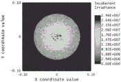
图6是本申请实施例的半导体激光器焊接装置的135um光纤端面能量分布。Fig. 6 is the energy distribution of the 135um fiber end face of the semiconductor laser welding device according to the embodiment of the present application.
图7是本申请实施例的半导体激光器焊接装置的135um光纤端面能量分布。Fig. 7 is the energy distribution of the 135um fiber end face of the semiconductor laser welding device according to the embodiment of the present application.
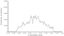
图8是本申请实施例的半导体激光器焊接装置的135um光纤的光束发散角。Fig. 8 is the beam divergence angle of the 135um optical fiber of the semiconductor laser welding device according to the embodiment of the present application.
图9是本申请实施例的半导体激光器焊接装置的聚焦焦点光斑形状。Fig. 9 is a focus spot shape of the semiconductor laser welding device according to the embodiment of the present application.
图10是本申请实施例的半导体激光器焊接装置的聚焦焦点光斑能量分布。Fig. 10 is the energy distribution of the focused focal spot of the semiconductor laser welding device according to the embodiment of the present application.
图11是本申请实施例的半导体激光器焊接装置的聚焦光束发散角。Fig. 11 is the divergence angle of the focused beam of the semiconductor laser welding device according to the embodiment of the present application.
图中,1、半导体激光器,2、石英端帽,3、准直透镜,4、第一振镜,5、振镜马达,6、凹透镜,7,聚焦透镜,8、透镜组,8.1、第一楔形透镜,8.2、第二楔形透镜,9、第二振镜,9.1、第一反射镜,9.2、反射镜座。In the figure, 1. Semiconductor laser, 2. Quartz end cap, 3. Collimating lens, 4. The first vibrating mirror, 5. Vibrating mirror motor, 6. Concave lens, 7. Focusing lens, 8. Lens group, 8.1, The first One wedge lens, 8.2, the second wedge lens, 9, the second vibrating mirror, 9.1, the first reflecting mirror, 9.2, the reflecting mirror seat.
具体实施方式Detailed ways
为了使本发明的目的、技术方案及优点更加清楚明白,以下结合附图及实施例,对本发明一种半导体激光器焊接装置进行进一步详细说明。应当理解,此处所描述的具体实施例仅用以解释本发明并不用于限定本发明。In order to make the purpose, technical solution and advantages of the present invention clearer, a semiconductor laser welding device of the present invention will be further described in detail below in conjunction with the accompanying drawings and embodiments. It should be understood that the specific embodiments described here are only used to explain the present invention and not to limit the present invention.
在本发明的描述中,除非另有说明,“多个”的含义是两个或两个以上;术语“中心”、“纵向”、“横向”、“上”、“下”、“左”、“右”、“内”、“外”、“前端”、“后端”、“头部”、“尾部”、“竖直”、“水平”、“顶”、“底”、“内”、“外”等指示的方位或位置关系为基于附图所示的方位或位置关系,仅是为了便于描述本发明和简化描述,而不是指示或暗示所指的装置或元件必须具有特定的方位、以特定的方位构造和操作,因此不能理解为对本发明的限制。此外,术语“第一”、“第二”、“第三”等仅用于描述目的,而不能理解为指示或暗示相对重要性。In the description of the present invention, unless otherwise stated, the meaning of "plurality" is two or more; , "Right", "Inner", "Outer", "Front", "Back", "Head", "Tail", "Vertical", "Horizontal", "Top", "Bottom", "Inner ", "outside" and other indicated orientations or positional relationships are based on the orientations or positional relationships shown in the drawings, which are only for the convenience of describing the present invention and simplifying the description, rather than indicating or implying that the referred device or element must have a specific Orientation, construction and operation in a particular orientation, therefore should not be construed as limiting the invention. In addition, the terms "first", "second", "third", etc. are used for descriptive purposes only and should not be construed as indicating or implying relative importance.
第一实施例first embodiment
请参见图1,本申请第一实施例提供一种半导体激光器焊接装置,包括:Please refer to Fig. 1, the first embodiment of the present application provides a semiconductor laser welding device, including:
半导体激光器1,所述半导体激光器1的输出功率在500-1500W之间,可以采用单波长的光束作为光源,输出光束的波长在800-1080nm之间,输出光束的NA在0.15-0.20之间,发散半角在8.53°-11.31°之间;所述半导体激光器1通过耦合光纤进行输出,其输出的光纤芯径在105-220μm之间,输出光束在光纤中进行全反射传输;A semiconductor laser 1, the output power of the semiconductor laser 1 is between 500-1500W, a single-wavelength beam can be used as a light source, the wavelength of the output beam is between 800-1080nm, and the NA of the output beam is between 0.15-0.20, The divergence half angle is between 8.53°-11.31°; the semiconductor laser 1 is output through a coupling fiber, the core diameter of the output fiber is between 105-220 μm, and the output beam is transmitted through total reflection in the fiber;
当对输出光束的功率和亮度要求更高时,所述半导体激光器1还可以采用复合波长的光束作为光源,通过波长合束或光谱合束技术进行多个波长的光束进行耦合,可以获得高亮度、高功率的输出光束;When the power and brightness of the output beam are required to be higher, the semiconductor laser 1 can also use a composite wavelength beam as a light source, and couple beams of multiple wavelengths through wavelength combining or spectral beam combining technology to obtain high brightness. , high power output beam;
所述半导体激光器1还内置有指示光源,该指示光源与输出光束耦合至同一跟光纤进行输出,该指示光源可以在激光焊接制程中起到指示以及安全的作用;The semiconductor laser 1 also has a built-in indicator light source, which is coupled to the same optical fiber as the output beam for output. The indicator light source can play an indicator and safety role in the laser welding process;
当所述半导体激光器1采用光纤芯径为135μm的光纤进行耦合输出时,输出端面的光斑大小、能量分布以及光束发散角如图6-图8所示。When the semiconductor laser 1 uses an optical fiber with a core diameter of 135 μm for coupling output, the spot size, energy distribution and beam divergence angle of the output end face are shown in FIGS. 6-8 .
石英端帽2,所述石英端帽的输出结构外径小于22mm,通过输出光纤和所述半导体激光器1进行熔接,所述石英端帽2可以降低端面输出光束的功率密度;
准直透镜3,所述准直透镜3的焦距在20.0-35.0mm之间,可以将经过所述石英端帽2的输出光束进行准直,将输出光束调整为平行输出的光束,准直后的输出光束的直径为6.0-12.0mm;
所述准直透镜3选择自平凸透镜、双面凸透镜、非球透镜中的一种;The
第一振镜4,所述第一振镜4包括有反射镜,所述反射镜镜面法线与输出光束光轴的夹角为60°,且所述反射镜表面镀有针对半导体激光光束波段的高反射镀膜,可以对经过准直透镜3的输出光束进行反射,调整输出光束的输出方向,使得输出光束的输出方向可以沿着图1中的y轴方向进行摆动,所述第一振镜4沿轴转动并调整光束的幅度为0°-3°之间,频率在0-100Hz之间;The first oscillating mirror 4, the first oscillating mirror 4 includes a reflector, the angle between the normal line of the mirror surface of the reflector and the optical axis of the output beam is 60°, and the surface of the reflector is coated with a coating for the wavelength band of the semiconductor laser beam. The high-reflection coating can reflect the output beam passing through the
凹透镜6,所述凹透镜6可以对经过第一振镜4的输出光束进行扩束,得到的输出光束的发散半角在5.7-7.5°之间,所成的光斑虚像大小在180-240μm之间;A concave lens 6, the concave lens 6 can expand the output beam passing through the first vibrating mirror 4, the divergence half angle of the obtained output beam is between 5.7-7.5°, and the size of the formed virtual spot image is between 180-240 μm;
可选的,所述凹透镜6可以选择平凹透镜或者双面凹透镜;Optionally, the concave lens 6 can be a plano-concave lens or a double-sided concave lens;
聚焦透镜7,所述聚焦透镜7选择自平凸透镜、双面凸透镜、非球透镜中的一种,有效焦距在60-70mm之间,可以对经过凹透镜6的输出光束进行聚焦,光束聚焦于距离该聚焦透镜7出光镜面120-200mm之间,该距离符合手持焊接的工作距离需求,聚焦后的输出光束可以焊接于工件表面。Focusing lens 7, the focusing lens 7 is selected from a plano-convex lens, a biconvex lens, and an aspheric lens, the effective focal length is between 60-70mm, and the output beam through the concave lens 6 can be focused, and the beam is focused at a distance The focusing lens 7 has a light output mirror surface of 120-200mm, which meets the working distance requirements of hand-held welding, and the focused output beam can be welded on the surface of the workpiece.
输出光束在经过所述凸透镜聚焦后,其光斑大小、能量分布以及发散角如图9-图11所示。After the output beam is focused by the convex lens, its spot size, energy distribution and divergence angle are shown in Figures 9-11.
经过聚焦后的输出光束的焦点处的光斑在220-360μm之间,发散半角在3.2-5.7°之间,功率密度在5.0×10⁵-3.0×10⁶W/cm2之间,满足激光深熔焊的需求。The spot at the focal point of the focused output beam is between 220-360 μm, the divergence half-angle is between 3.2-5.7°, and the power density is between 5.0×10⁵ -3.0×10⁶ W/cm2 , satisfying the laser depth Welding requirements.
本申请实施例所述半导体激光器焊接装置还包括振镜马达5,所述振镜马达5与所述第一振镜4进行连接,通过所述振镜马达5带动所述第一振镜4沿图1中虚线轴的方向进行往复旋转,使得所述所述第一振镜4可以调整输出光束的输出方向。The semiconductor laser welding device described in the embodiment of the present application also includes a vibrating mirror motor 5, which is connected to the first vibrating mirror 4, and the vibrating mirror motor 5 drives the first vibrating mirror 4 along the The direction of the dotted axis in FIG. 1 is reciprocatingly rotated, so that the first vibrating mirror 4 can adjust the output direction of the output beam.
在本申请实施例中,所述半导体激光器1产生输出光束,该输出光束经过所述石英端帽2降低光输出功率密度,所述准直透镜3进行光线准直,所述第一振镜4进行光路的方向调整,所述凹透镜6进行光的扩束,以及所述聚焦透镜7进行光的聚焦,得到能用于焊接工作的输出光束。In the embodiment of the present application, the semiconductor laser 1 generates an output beam, the output beam passes through the
第二实施例second embodiment
请参见图1-图3,本申请第二实施例提供一种半导体激光器焊接装置,除了包括上述第一实施例所记述的所有特征之外,还包括:Please refer to Fig. 1-Fig. 3, the second embodiment of the present application provides a semiconductor laser welding device, in addition to including all the features described in the first embodiment above, it also includes:
电磁装置(图未示),所述电磁装置设置在凹透镜6的周围并与凹透镜6嵌接,通过磁力约束或者电动机械约束的方式使得凹透镜6可以沿着输出光束光轴的方向平行移动,从而调节经过聚焦透镜7聚焦后的输出光束的光斑大小,以及调整激光焊接工作的距离;An electromagnetic device (not shown in the figure), the electromagnetic device is arranged around the concave lens 6 and embedded with the concave lens 6, and the concave lens 6 can move in parallel along the direction of the optical axis of the output beam by means of magnetic force constraints or electromechanical constraints, so that Adjust the spot size of the output beam focused by the focusing lens 7, and adjust the distance of the laser welding work;
透镜组8,所述透镜组8设置在第一振镜4与凹透镜6之间的光路,所述透镜组8包括第一楔形透镜8.1以及第二楔形透镜8.2,所述第一楔形透镜8.1以及第二楔形透镜8.2可以选择相同的直角三棱镜组成,所述第一楔形透镜8.1以及第二楔形透镜8.2呈现中心对称分布,其中第一楔形透镜8.1以及第二楔形透镜8.2的其中一个是固定,另一个楔形透镜可以沿着与光轴垂直的方向上下移动,使得输出光束在经过透镜组8的时候可以在沿着与光轴垂直的方向上下移动,从而调节经过聚焦透镜7聚焦后的输出光束的光斑的位置;A
通过第一振镜4和透镜组8的组合可实现光斑沿垂直纸面和平行纸面两个方向的摆动。优化焊接扫描的路径,达到更好的焊接效果。The combination of the first vibrating mirror 4 and the
第三实施例third embodiment
请参见图1、图4及图5,本申请第三实施例提供一种半导体激光器焊接装置,除了包括上述第一实施例所记述的所有特征之外,还包括:Please refer to Fig. 1, Fig. 4 and Fig. 5, the third embodiment of the present application provides a semiconductor laser welding device, in addition to including all the features described in the first embodiment above, it also includes:
第二振镜9,所述第二振镜9设置在第一振镜4与凹透镜6之间的光路,所述第二振镜9包括第一反射镜9.1及反射镜座9.2,所述第一反射镜9.1固定在反射镜座9.2上,通过反射镜座9.2的偏摆,可以带动第一反射镜9.1在垂直于输出光束所在纸面上的轴(y轴)上进行转动,转动的幅度在0°-3°之间,频率在0-100Hz之间,所述第一反射镜9.1可以改变经过第一振镜4的输出光束的平行光方向,使其可以到达凹透镜6;The second
通过第一振镜4和第二振镜9的组合可实现光斑沿垂直纸面和平行纸面两个方向的摆动。优化焊接扫描的路径,达到更好的焊接效果。The combination of the first vibrating mirror 4 and the second vibrating
本申请技术方案通过多个透镜对半导体激光器产生的输出光束进行调整,优化了现有的手持式激光焊接光路设计,提高了半导体激光器输出光束的质量,使其能应用于激光手持焊接的制程;本申请采用了半导体激光器作为光源,其波长相对于光纤激光器的光源更短,焊接制程中对待加工材料有更高的吸收系数,具备更高的加工效率;本申请采用的半导体激光器具有光电转换效率更高的特点,节约加工成本;本申请采用了耦合光纤输出的半导体激光器,输出的光近似于平顶光,在进行激光焊接过程中更不容易发生飞溅,降低加工元件的损伤。The technical solution of this application adjusts the output beam generated by the semiconductor laser through multiple lenses, optimizes the existing hand-held laser welding optical path design, improves the quality of the output beam of the semiconductor laser, and makes it applicable to the laser hand-held welding process; This application uses a semiconductor laser as a light source, its wavelength is shorter than that of a fiber laser, the material to be processed in the welding process has a higher absorption coefficient, and has higher processing efficiency; the semiconductor laser used in this application has photoelectric conversion efficiency Higher features, saving processing cost; this application uses a semiconductor laser coupled with optical fiber output, the output light is similar to flat-top light, and spatter is less likely to occur during laser welding, reducing damage to processing components.
Claims (10)
Priority Applications (1)
| Application Number | Priority Date | Filing Date | Title |
|---|---|---|---|
| CN202211422947.2ACN115673545A (en) | 2022-11-15 | 2022-11-15 | Semiconductor laser welding device |
Applications Claiming Priority (1)
| Application Number | Priority Date | Filing Date | Title |
|---|---|---|---|
| CN202211422947.2ACN115673545A (en) | 2022-11-15 | 2022-11-15 | Semiconductor laser welding device |
Publications (1)
| Publication Number | Publication Date |
|---|---|
| CN115673545Atrue CN115673545A (en) | 2023-02-03 |
Family
ID=85052784
Family Applications (1)
| Application Number | Title | Priority Date | Filing Date |
|---|---|---|---|
| CN202211422947.2APendingCN115673545A (en) | 2022-11-15 | 2022-11-15 | Semiconductor laser welding device |
Country Status (1)
| Country | Link |
|---|---|
| CN (1) | CN115673545A (en) |
Cited By (1)
| Publication number | Priority date | Publication date | Assignee | Title |
|---|---|---|---|---|
| CN116352272A (en)* | 2023-04-13 | 2023-06-30 | 长春慧眼神光光电科技有限公司 | Multi-point output laser light source |
Citations (9)
| Publication number | Priority date | Publication date | Assignee | Title |
|---|---|---|---|---|
| JP2001284732A (en)* | 2000-03-31 | 2001-10-12 | Matsushita Electric Ind Co Ltd | Multi-wavelength laser light emitting device, semiconductor laser array element used in the device, and method of manufacturing semiconductor laser array element |
| CN101486255A (en)* | 2008-01-16 | 2009-07-22 | 俞国麟 | Apparatus for laser welding thermoplastic plastic parts |
| JP2010079233A (en)* | 2008-09-26 | 2010-04-08 | Act Research Corp | Method and system for quick focusing and zooming for volume 3d display and camera |
| CN211361033U (en)* | 2020-06-19 | 2020-08-28 | 深圳市创鑫激光股份有限公司 | Multi-wavelength high-power laser processing system |
| CN214313862U (en)* | 2021-01-26 | 2021-09-28 | 深圳市星汉激光科技股份有限公司 | A semiconductor laser for laser welding |
| CN113814583A (en)* | 2021-07-07 | 2021-12-21 | 广东原点智能技术有限公司 | A kind of laser rotary cutting system and rotary cutting method |
| CN216355290U (en)* | 2021-09-10 | 2022-04-19 | 苏州创鑫激光科技有限公司 | Heat dissipation system and portable laser welding equipment |
| CN217253591U (en)* | 2021-06-15 | 2022-08-23 | 苏州创鑫激光科技有限公司 | Optical path assembly for laser processing head and hand-held laser processing head |
| CN217253603U (en)* | 2021-09-10 | 2022-08-23 | 苏州创鑫激光科技有限公司 | Laser welding head and laser |
- 2022
- 2022-11-15CNCN202211422947.2Apatent/CN115673545A/enactivePending
Patent Citations (9)
| Publication number | Priority date | Publication date | Assignee | Title |
|---|---|---|---|---|
| JP2001284732A (en)* | 2000-03-31 | 2001-10-12 | Matsushita Electric Ind Co Ltd | Multi-wavelength laser light emitting device, semiconductor laser array element used in the device, and method of manufacturing semiconductor laser array element |
| CN101486255A (en)* | 2008-01-16 | 2009-07-22 | 俞国麟 | Apparatus for laser welding thermoplastic plastic parts |
| JP2010079233A (en)* | 2008-09-26 | 2010-04-08 | Act Research Corp | Method and system for quick focusing and zooming for volume 3d display and camera |
| CN211361033U (en)* | 2020-06-19 | 2020-08-28 | 深圳市创鑫激光股份有限公司 | Multi-wavelength high-power laser processing system |
| CN214313862U (en)* | 2021-01-26 | 2021-09-28 | 深圳市星汉激光科技股份有限公司 | A semiconductor laser for laser welding |
| CN217253591U (en)* | 2021-06-15 | 2022-08-23 | 苏州创鑫激光科技有限公司 | Optical path assembly for laser processing head and hand-held laser processing head |
| CN113814583A (en)* | 2021-07-07 | 2021-12-21 | 广东原点智能技术有限公司 | A kind of laser rotary cutting system and rotary cutting method |
| CN216355290U (en)* | 2021-09-10 | 2022-04-19 | 苏州创鑫激光科技有限公司 | Heat dissipation system and portable laser welding equipment |
| CN217253603U (en)* | 2021-09-10 | 2022-08-23 | 苏州创鑫激光科技有限公司 | Laser welding head and laser |
Non-Patent Citations (1)
| Title |
|---|
| 陈继民等: "激光现代制造技术", vol. 1, 31 October 2007, 国防工业出版社, pages: 115* |
Cited By (1)
| Publication number | Priority date | Publication date | Assignee | Title |
|---|---|---|---|---|
| CN116352272A (en)* | 2023-04-13 | 2023-06-30 | 长春慧眼神光光电科技有限公司 | Multi-point output laser light source |
Similar Documents
| Publication | Publication Date | Title |
|---|---|---|
| JP5496370B2 (en) | Optical fiber and laser processing apparatus including the same | |
| CN103182604B (en) | Laser compound welding method and system | |
| US12263541B2 (en) | Laser processing device and laser processing method using same | |
| US7088749B2 (en) | Green welding laser | |
| CN202021424U (en) | Laser wire filling welding machine with non-stable cavity and coaxial wire feed | |
| CN114535609B (en) | Method for regulating and controlling fusing process of metal powder by using ultrahigh frequency vibration laser beam | |
| CN106498387B (en) | Laser cladding apparatus based on the pre- hot-working slow cooling power of liquid crystal modulation | |
| CN110681992A (en) | An adjustable broadband laser processing optical system and processing method | |
| CN110586939A (en) | Blue-green laser micro-melting forming method and device for high-reflection material | |
| CN110977152A (en) | A SLM dual-laser composite processing system | |
| CN210967462U (en) | A Tunable Broadband Laser Processing Optical System | |
| CN108500491A (en) | The coaxial compound increasing material manufacturing device and method of laser-cold metal transfer electric arc | |
| CN108544092A (en) | A kind of coaxial wire feed deposition head for laser metal printing | |
| CN114192971A (en) | Laser processing light path system, method and application thereof | |
| CN115673545A (en) | Semiconductor laser welding device | |
| WO2024174964A1 (en) | Laser spot dynamic control method and laser cutting system | |
| KR20220121900A (en) | laser device | |
| CN1299404C (en) | Laser apparatus | |
| CN213729961U (en) | Laser and electric arc composite welding gun | |
| CN108899753B (en) | End-face uniform pumping solid laser | |
| CN115446481B (en) | A precision laser deep hole processing device and processing method | |
| CN216758172U (en) | Blue light infrared dual-wavelength coaxial composite laser additive manufacturing device | |
| CN100486063C (en) | High power pulsed laser maladjustment proof resonant cavity | |
| CN212704975U (en) | Handheld laser welding gun | |
| CN116117306A (en) | Laser galvanometer scanning processing head |
Legal Events
| Date | Code | Title | Description |
|---|---|---|---|
| PB01 | Publication | ||
| PB01 | Publication | ||
| SE01 | Entry into force of request for substantive examination | ||
| SE01 | Entry into force of request for substantive examination |