CN115670756A - A lumbar posterior zero-profile fusion device system and its application method - Google Patents
A lumbar posterior zero-profile fusion device system and its application methodDownload PDFInfo
- Publication number
- CN115670756A CN115670756ACN202110853375.2ACN202110853375ACN115670756ACN 115670756 ACN115670756 ACN 115670756ACN 202110853375 ACN202110853375 ACN 202110853375ACN 115670756 ACN115670756 ACN 115670756A
- Authority
- CN
- China
- Prior art keywords
- connecting seat
- fusion device
- fusion
- posterior
- locking
- Prior art date
- Legal status (The legal status is an assumption and is not a legal conclusion. Google has not performed a legal analysis and makes no representation as to the accuracy of the status listed.)
- Granted
Links
Images


Landscapes
- Prostheses (AREA)
- Surgical Instruments (AREA)
Abstract
Translated fromChinese
Description
Translated fromChinese技术领域technical field
本发明涉及了腰椎后路植入技术领域,特别是涉及了一种腰椎后路零切迹融合器系统及其使用方法。The invention relates to the technical field of lumbar posterior implantation, in particular to a lumbar posterior zero-profile fusion device system and a method for using the same.
背景技术Background technique
脊椎由一个椎体、两个椎弓根、两个椎板、两个横突、四个关节突和一个棘突组成的骨结构、分颈椎骨、胸椎骨、腰椎骨、骶椎骨、尾椎骨。由于不良习惯或由于瞬间的不适当行为就会导致腰椎疾病。目前随着人们脊椎疾病的频繁发病,对脊椎的治疗手段越来越有针对性,当前腰椎融合手术是目前治疗腰椎疾病的主要手段,腰椎融合器作为腰椎椎间界面融合技术中重要的内置物起着越来越重要的作用。腰椎融合器一般分有应用于前路的融合器和应用于后路的融合器。由于腰椎前路可操作空间大,前路融合器应用风险相比后路融合器的小,目前前路融合器取得了良好的效果但需要二个手术切口,手术复杂,创伤大,风险高。为此,业内开发出了后路融合器,如中国实用新型CN203693843U公开了一种腰椎后路侧置椎间固定融合器,又如中国实用新型CN209316161U公开了零切迹腰椎后路融合器等等。The spine consists of one vertebral body, two pedicles, two lamina, two transverse processes, four articular processes and one spinous process, divided into cervical vertebrae, thoracic vertebrae, lumbar vertebrae, sacral vertebrae, and coccygeal vertebrae . Lumbar spine disease can be caused by bad habits or by momentary inappropriate behavior. At present, with the frequent occurrence of spinal diseases, the treatment methods for the spine are becoming more and more targeted. The current lumbar fusion surgery is the main method for the treatment of lumbar diseases. The lumbar fusion device is an important built-in object in the fusion technology of the lumbar intervertebral interface. play an increasingly important role. Lumbar fusion devices are generally divided into fusion devices used in the anterior approach and fusion devices used in the posterior approach. Due to the large operable space in the anterior approach of the lumbar spine, the risk of anterior fusion fusion is lower than that of posterior fusion fusion. At present, anterior fusion fusion has achieved good results but requires two surgical incisions. The operation is complicated, traumatic and risky. For this reason, the industry has developed a posterior fusion device, such as the Chinese utility model CN203693843U which discloses a lumbar posterior lateral intervertebral fixation fusion device, and the Chinese utility model CN209316161U which discloses a zero-notch lumbar posterior fusion device, etc. .
腰椎后路置入融合器手术过程是:椎管的横径约2.5厘米,里面有硬膜囊,两侧有神经根,在进行置入融合器时,先要把一侧的神经根、硬膜囊一起向对侧牵开才显露椎间盘,切除突出的椎间盘后再置入融合器,再者置入后的融合器的顶端(即所述融合器的前侧顶部)要比椎体后缘深2-4毫米左右。The operation process of inserting the fusion device in the posterior approach of the lumbar spine is as follows: the transverse diameter of the spinal canal is about 2.5 cm, there is a dural sac inside, and there are nerve roots on both sides. The intervertebral disc is exposed only when the membrane capsule is retracted to the opposite side. The intervertebral disc is resected and then the fusion cage is placed. Furthermore, the top of the fusion cage after placement (that is, the front top of the fusion cage) is larger than the posterior edge of the vertebral body. About 2-4mm deep.
现有技术的腰椎后路融合器(至少包括但不限于上述两个实用新型所公开的后路融合器)通过打入器置入椎体间的融合器之后,打入器撤出后,由于神经根、硬膜囊回位,覆盖或部分覆盖了融合器顶端,使得顶端几乎无法直接观察到,更无法在融合器顶端旋入锁定钉;目前现有的后路置入融合器在具体临床实践中是无法操作的,其原因是:把神经根和硬膜囊向对侧牵开只能到椎管中线,约1.3厘米左右,在这个宽度下置入宽为1厘米的融合器,为了旋入锁定钉需要二次牵开神经根、硬膜囊会造成神经根受到过度牵开或频繁牵开而损伤,以及旋入锁定钉极易造成对周围的神经根、硬膜囊等神经组织的磨损损伤,风险性很高。The posterior lumbar fusion device of the prior art (including but not limited to the posterior fusion device disclosed in the above two utility models) is inserted into the intervertebral fusion device through the driver, and after the driver is withdrawn, due to Nerve roots and dural sacs return, covering or partially covering the top of the fusion cage, making it almost impossible to directly observe the top of the fusion cage, let alone screw the locking nail on the top of the fusion cage; In practice, it is impossible to operate. The reason is that retracting the nerve root and dural sac to the opposite side can only reach the midline of the spinal canal, about 1.3 cm. Screwing in the locking screw requires secondary retraction of the nerve root, and the dural sac will cause damage to the nerve root due to excessive retraction or frequent retraction, and screwing in the locking screw can easily cause damage to the surrounding nerve roots, dural sac and other nerve tissues. The risk of wear damage is high.
即使如中国实用新型CN209316161U公开的融合器中采用了具有导向作用的锁紧孔的固定体,在实际后路置入椎体临床手术中,由于固定体是与融合器主体固定连接在一起置入椎体的,则置入后所述固定体顶端至少不超出椎体后缘,依然存在如上述无法直视到锁紧孔的情况,也即无法旋入锁定钉;即使在某些情况下可以牵开神经根、硬膜囊等神经组织,部分显露出融合器顶端以看到锁定孔,但也仅仅是看到锁定孔,而将一定长度的锁定钉倾斜一定角度经锁定孔旋入椎体过程中,不仅锁定孔外周面的螺纹存在接触损伤神经根、硬膜囊等神经组织的高风险,而且锁定钉是倾斜旋入相比垂直旋入需要将神经根、硬膜囊等神经组织牵开更大的操作空间这会造成更大的手术风险。Even if the fusion device disclosed in the Chinese utility model CN209316161U adopts a fixing body with a guiding locking hole, in the actual posterior vertebral body clinical operation, since the fixing body is fixedly connected with the main body of the fusion device and inserted together For the vertebral body, the top of the fixed body does not exceed the posterior edge of the vertebral body at least after it is placed, and there is still the situation that the locking hole cannot be seen directly as mentioned above, that is, the locking nail cannot be screwed in; even in some cases it can Nerve tissues such as the nerve root and dural sac are retracted to partially expose the top of the fusion cage to see the locking hole, but only the locking hole is seen, and a certain length of locking nail is screwed into the vertebral body through the locking hole at a certain angle. During the process, not only the thread on the outer peripheral surface of the locking hole has a high risk of contacting nerve roots, dural sac and other nerve tissues, but also the locking nail needs to pull the nerve roots, dural sac and other nerve tissues when it is screwed in obliquely compared with vertical screwing. Opening a larger operating space will cause greater surgical risks.
虽然现有已有零切迹腰椎后路融合器,但由于腰椎后路结构复杂,可操作空间小,具体应用时当前的零切迹腰椎后路融合器的可操作性不高,需要多次牵开神经根、硬膜囊等神经组织以及锁紧钉倾斜旋入过程存在损伤神经根、硬膜囊等神经组织的较大风险,故现有零切迹腰椎后路融合器真正应用于临床手术还是有很大的挑战性和手术风险。Although there are existing zero-profile posterior lumbar fusion devices, due to the complex structure of the posterior lumbar spine and the small operable space, the current zero-profile posterior lumbar fusion devices are not very operable in specific applications and need to be performed multiple times. There is a greater risk of damage to nerve roots, dural sac and other nerve tissues during the retraction of nerve roots and dural sac and the oblique screwing of locking screws. Therefore, the existing zero-profile posterior lumbar fusion device is really used in clinical practice. Surgery still has great challenges and surgical risks.
发明内容Contents of the invention
为了解决上述技术问题,本发明提供了一种腰椎后路零切迹融合器系统及其使用方法。In order to solve the above technical problems, the present invention provides a lumbar posterior zero-profile fusion device system and its application method.
本发明所要解决的技术问题通过以下技术方案予以实现:The technical problem to be solved by the present invention is realized through the following technical solutions:
一种腰椎后路零切迹融合器系统,其包括融合器及打入器;所述打入器包括连接座,其可拆卸连接在所述融合器上;所述融合器前侧设置有至少两个倾斜的锁定孔;所述连接座轴向高度为1.5cm以上;所述连接座设置有至少两条倾斜贯穿的通道,每一所述通道的出口端与一所述锁定孔相对应;所述通道轴线与所述连接座轴线之间的夹角为30~35°。A lumbar posterior zero-profile fusion device system, which includes a fusion device and a driver; the driver includes a connecting seat, which is detachably connected to the fusion device; the front side of the fusion device is provided with at least Two inclined locking holes; the axial height of the connecting seat is more than 1.5cm; the connecting seat is provided with at least two obliquely penetrating channels, and the outlet end of each channel corresponds to one of the locking holes; The included angle between the channel axis and the connecting seat axis is 30-35°.
作为本发明提供的所述的腰椎后路零切迹融合器系统的一种优选实施方式,所述锁定孔与所述通道共轴线设置。As a preferred embodiment of the posterior lumbar zero-profile fusion cage system provided by the present invention, the locking hole is arranged coaxially with the channel.
作为本发明提供的所述的腰椎后路零切迹融合器系统的一种优选实施方式,所述连接座轴向高度为1.5~2.0cm。As a preferred embodiment of the posterior lumbar zero-profile fusion device system provided by the present invention, the axial height of the connecting seat is 1.5-2.0 cm.
作为本发明提供的所述的腰椎后路零切迹融合器系统的一种优选实施方式,所述融合器与连接座之间的可拆卸连接为螺纹式连接结构或卡扣式连接结构。As a preferred embodiment of the lumbar posterior zero-profile fusion device system provided by the present invention, the detachable connection between the fusion device and the connecting seat is a threaded connection structure or a snap-fit connection structure.
作为本发明提供的所述的腰椎后路零切迹融合器系统的一种优选实施方式,所述螺纹式连接结构包括设置在所述融合器前侧顶部的螺纹孔和设置在所述连接座上的螺纹头,所述螺纹头与所述螺纹孔相配合。As a preferred embodiment of the lumbar posterior zero-profile fusion cage system provided by the present invention, the threaded connection structure includes a threaded hole on the front top of the fusion cage and a threaded hole on the connecting seat. The threaded head on the threaded head is matched with the threaded hole.
作为本发明提供的所述的腰椎后路零切迹融合器系统的一种优选实施方式,所述通道的入口端设置在所述连接座的前侧顶部。As a preferred implementation of the lumbar posterior zero-profile fusion fusion system provided by the present invention, the entrance end of the channel is arranged at the front top of the connecting seat.
作为本发明提供的所述的腰椎后路零切迹融合器系统的一种优选实施方式,所述通道的入口端设置在所述连接座的前侧侧部。As a preferred embodiment of the posterior lumbar zero-profile fusion fusion system provided by the present invention, the inlet end of the channel is arranged at the front side of the connecting seat.
作为本发明提供的所述的腰椎后路零切迹融合器系统的一种优选实施方式,所述融合器包括融合器本体及在所述融合器本体上设置有贯穿的人造骨填充孔。As a preferred embodiment of the lumbar posterior zero-profile fusion device system provided by the present invention, the fusion device includes a fusion device body and a penetrating artificial bone filling hole is arranged on the fusion device body.
作为本发明提供的所述的腰椎后路零切迹融合器系统的一种优选实施方式,所述融合器本体外表面上设置有波纹结构。As a preferred embodiment of the posterior lumbar zero-profile fusion cage system provided by the present invention, the outer surface of the fusion cage body is provided with a corrugated structure.
作为本发明提供的所述的腰椎后路零切迹融合器系统的一种优选实施方式,两个所述锁定孔设置在所述融合器前侧的两端部;两个所述锁定孔的倾斜方向相反。As a preferred embodiment of the lumbar posterior zero-profile fusion device system provided by the present invention, the two locking holes are arranged at both ends of the front side of the fusion device; The direction of inclination is opposite.
一种腰椎后路零切迹融合器系统的使用方法,包括以下步骤:在完成腰椎后路椎管减压、椎间盘切除手术后,通过打入器主体把相互连接的融合器和连接座,经过椎管由后向前置入椎体间,选择所需长度的锁定钉装入通道内,把锁定钉从锁定孔旋出进入椎体内,以将锁定钉锁定于所述融合器的前侧和椎体内完成所述融合器与所述椎体的锁定;旋入所有锁定钉后,通过打入器主体将所述连接座从融合器上拆离。A method for using a lumbar posterior zero-profile fusion device system, comprising the following steps: after the lumbar posterior spinal canal decompression and intervertebral discectomy are completed, the fusion device and the connecting seat connected to each other are driven into the main body of the device, and passed through The spinal canal is inserted into the vertebral body from the back to the front, and the locking nail of the required length is selected and loaded into the channel, and the locking nail is screwed out from the locking hole into the vertebral body, so as to lock the locking nail on the front side of the fusion cage The locking of the fusion device and the vertebral body is completed in the vertebral body; after all the locking nails are screwed in, the connecting seat is detached from the fusion device through the main body of the driver.
本发明具有如下有益效果:The present invention has following beneficial effect:
本发明将与融合器可拆卸连接的连接座的轴向高度为1.5cm以上,以及在连接座内设置有至少两条倾斜贯穿的通道,每一所述通道的出口端与一所述锁定孔相对应;所述通道轴线与所述连接座轴线之间的夹角为30~35°。如此设计,在完成腰椎后路椎管减压、椎间盘切除手术后,把相互连接的融合器和连接座,经过椎管由后向前置入椎体间,再用弹性螺丝批把所需长度的锁定钉插入所述通道并从锁定孔旋出进入椎体内,以将锁定钉锁定于所述融合器的前侧和椎体内完成所述融合器与所述椎体的锁定,最后移走所述打入器时连同移走连接座。According to the present invention, the axial height of the connecting seat detachably connected with the fusion device is more than 1.5 cm, and at least two obliquely penetrating channels are arranged in the connecting seat, and the outlet end of each channel is connected with one of the locking holes. Correspondingly; the included angle between the channel axis and the connecting seat axis is 30-35°. With this design, after completing the decompression of the lumbar posterior spinal canal and intervertebral disc resection, the interconnected fusion device and connecting seat are inserted into the intervertebral body from the back to the front through the spinal canal, and then the required length is adjusted by an elastic screwdriver. The locking nail is inserted into the channel and screwed out from the locking hole into the vertebral body, so as to lock the locking nail on the front side of the fusion device and the vertebral body to complete the locking of the fusion device and the vertebral body, and finally move When walking the driver, remove the connecting seat together.
通过本发明融合器系统,仅需一次牵开神经根、硬膜囊等神经组织,通过打入器将所述融合器置入椎体间后不直接移走连接座,根据实际可钉入深度选择合适长度的锁定钉,然后插入连接座内的一倾斜通道内进入锁定孔再旋入到椎体内,如此连接座轴向高度为1.5cm以上,加上所述通道轴线与所述连接座轴线之间的夹角为30~35°,则倾斜通道的入口端完全是高于神经根、硬膜囊等神经组织,倾斜通道相当一个导管作用,使融合器外以及连接座周围的神经组织受到保护,在旋入锁定钉的过程中,锁定钉以及螺丝批是完全在连接座及融合器进行,不与周围神经组织接触,以避免甚至杜绝在旋入锁定钉的过程中发生损伤椎体周围神经组织的意外,同时本发明腰椎后路零切迹融合器系统应用时仅需一个椎管后路切口,不需要再另作一个椎管前路切口,可大大降低手术费用、手术风险、手术创伤及手术时间,有较好的社会及经济效益。Through the fusion device system of the present invention, it is only necessary to retract nerve tissues such as nerve roots and dural sac once, and the fusion device is inserted into the vertebral body through the injector without directly removing the connecting seat, and the depth of the fusion can be nailed according to the actual situation. Choose a locking nail with a suitable length, insert it into an inclined channel in the connecting seat, enter the locking hole and screw it into the vertebral body, so that the axial height of the connecting seat is more than 1.5cm, plus the axis of the channel and the connecting seat The angle between the axes is 30-35°, the entrance of the inclined channel is completely higher than the nerve roots, dural sac and other nerve tissues, and the inclined channel acts as a conduit, so that the nerve tissue outside the fusion cage and around the connecting seat Protected, during the process of screwing in the locking screw, the locking screw and the screwdriver are completely carried out on the connecting seat and fusion cage, without contact with the surrounding nerve tissue, so as to avoid or even eliminate the damage to the vertebral body during the screwing in of the locking screw accidents in the peripheral nerve tissue, and at the same time, the application of the lumbar posterior zero-notch fusion device system of the present invention only requires one posterior spinal canal incision, and does not need to make another anterior spinal canal incision, which can greatly reduce surgical costs, surgical risks, Surgical trauma and operation time have better social and economic benefits.
本发明连接座内设置的倾斜通道,不仅用于容纳限定整个或大部分的锁定钉和螺丝批进出路径以避免现有融合器仅在头部开设导入孔造成锁定钉开始旋入时出现晃动和偏离预设倾斜角度的问题,还将通道轴线与所述连接座轴线之间的夹角为30~35°使得通道的长度足够长可容纳不同长度锁定钉,便于根据椎体情况选择合适长度的锁定钉进一步提高融合器与两侧椎体的锁定稳定性,解决了现有内藏锁定钉的融合器置入椎体间后无法灵活调整锁定钉长度的问题。The inclined channel provided in the connecting seat of the present invention is not only used to accommodate and limit the entire or most of the locking nails and the screwdriver access path to avoid shaking and swaying when the locking nails start to be screwed in because the existing cage only has an introduction hole in the head. For the problem of deviating from the preset inclination angle, the included angle between the axis of the channel and the axis of the connecting seat is 30-35° so that the length of the channel is long enough to accommodate locking nails of different lengths, which is convenient for selecting the appropriate length according to the vertebral body condition. The locking nail further improves the locking stability between the fusion cage and the vertebral bodies on both sides, and solves the problem that the length of the locking nail cannot be flexibly adjusted after the fusion cage with built-in locking nails is placed between the vertebral bodies.
附图说明Description of drawings
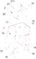
图1为本发明融合器系统的结构示意图;Fig. 1 is a schematic structural view of the fuser system of the present invention;
图2为本发明融合器系统的分解示意图;Fig. 2 is an exploded schematic view of the fuser system of the present invention;
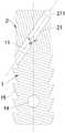
图3为图1中A-A处的剖视图;Fig. 3 is the sectional view of A-A place among Fig. 1;
图4为本发明融合器系统的使用方法流程图;Fig. 4 is a flow chart of the use method of the fuser system of the present invention;
图5为本发明融合器系统的使用过程示意图。Fig. 5 is a schematic diagram of the use process of the fusion device system of the present invention.
具体实施方式Detailed ways
以下结合具体实施例和附图对本发明的技术方案作进一步详细说明,应当理解,以下实施例仅仅用以解释本发明,并不用于限定本发明。The technical solutions of the present invention will be described in further detail below in conjunction with specific embodiments and accompanying drawings. It should be understood that the following embodiments are only used to explain the present invention and are not intended to limit the present invention.
请参考图1-3,本发明提供了一种腰椎后路零切迹融合器系统,其包括融合器1及打入器,所述打入器用于将所述融合器1从所述腰椎后路置入椎体间。具体地,所述打入器包括打入器本体(图中未显示)及与所述打入器本体连接的连接座2,其中所述连接座2可拆卸连接在所述融合器1上,所述打入器本体用于将所述连接座2和融合器1一起置入所述椎体间以及将所述连接座2拆离所述融合器1以从所述椎体间移出所述连接座2。所述融合器1前侧设置有至少两个倾斜的锁定孔11,所述锁定孔11用于锁定钉3穿过以旋入椎体且将其限位固定在所述融合器1上。所述连接座2轴向高度h为1.5cm以上;所述连接座2设置有至少两条倾斜贯穿的通道21,每一所述通道21的出口端与一所述锁定孔11相对应,当所述锁定钉3插入所述通道21后可沿通道21直接进入穿过所述锁定孔11;所述通道21轴线与所述连接座2轴线之间的夹角a为30~35°,如此设计不仅保证所述通道21长度足够长,而且保证所述锁定钉3以有效倾斜角度旋入椎体使得所述融合器1与椎体连接更稳定。Please refer to Figures 1-3, the present invention provides a posterior lumbar fusion device system with zero profile, which includes a
在本发明中,所述锁定孔11与所述通道21共轴线设置,如此设计,有利于所述锁定钉3沿着所述通道21顺利且无偏位的进入且穿过所述锁定孔11,使得所述锁定钉3有效地以预设倾斜角度旋入椎体。还可以理解的是,所述锁定孔11相对所述融合器1轴线的倾斜角度与所述通道21相对所述连接座2轴线的倾斜角度是一样的。In the present invention, the locking
在本发明中,所述连接座2轴向高度为1.5~2.0cm,高度设计过短,类似于现有后路融合器1在头部设置的导入孔,难以有效露出锁定孔11以及难以起到保护后路神经组织的作用,高度设计过长,不利于操作。In the present invention, the axial height of the connecting
在本发明中,所述融合器1与连接座2之间的可拆卸连接为螺纹式连接结构或卡扣式连接结构。具体地,所述螺纹式连接结构包括设置在所述融合器1前侧顶部的螺纹孔12和设置在所述连接座2上的螺纹头,所述螺纹头与所述螺纹孔12相配合。具体实现时,可通过所述打入器主体旋转带动所述连接座2的螺纹头旋出所述螺纹孔12,实现从所述融合器1上拆离所述连接座2。需要说明的是,所述打入器主体是现有常规部件,其起到将连接座2和融合器1置入椎体间以及将所述连接座2拆离所述融合器1的作用即可。值得注意的是,所述打入器主体与连接座2之间可以是一体式连接,也可以是独立式连接,这里的独立式连接是指打入器主体与连接座2是相互独立的,需要打入器主体作用于所述连接座2时,再将所述打入器主体连接在所述连接座2上。进一步地,所述打入器主体经过连接件与所述连接座2进行可拆卸连接,使得所述打入器主体通过连接件驱动所述连接座2移动以及旋转等等动作。In the present invention, the detachable connection between the
在本发明某些实施例中,所述通道21的入口端211设置在所述连接座2的前侧顶部,在其他实施例中,所述通道21的入口端211设置在所述连接座2的前侧侧部。由于所述连接座2轴向高度h为1.5cm以上,加上所述通道21轴线与所述连接座2轴线之间的夹角a为30~35°,则倾斜通道21的入口端211无论是设计在所述连接座2的前侧顶部还是侧部,均完全高于神经根、硬膜囊等神经组织,倾斜通道21相当一个导管作用,使融合器1外以及连接座2周围的神经组织受到保护,在旋入锁定钉3的过程中,锁定钉3以及螺丝批是完全在连接座2及融合器1进行,不与周围神经组织接触,以避免甚至杜绝在旋入锁定钉3的过程中发生损伤椎体周围神经组织的意外。In some embodiments of the present invention, the
在本发明中,所述融合器1包括融合器本体13及在所述融合器本体13上设置有贯穿的人造骨填充孔14。具体地,人造骨填充孔14中可以灌入人造骨材料,人造骨可以与腰椎融为一体,便于加快术后恢复。具体地,在本申请实施例中,所述人造骨填充孔14沿所述融合器1朝向椎体的方向设置并贯穿其两面,这样方便人造骨材料直接接触两椎体。In the present invention, the
在本发明中,所述融合器本体13外表面上设置有波纹结构15。所述波纹结构15凸出融合器1外表面,能防止融合器1在使用时相对椎骨滑动。可以理解的是,所述波纹结构15还可以设置成其他类似增大摩擦力的结构。In the present invention,
在本发明中,两个所述锁定孔11设置在所述融合器1前侧的两端部;两个所述锁定孔11的倾斜方向相反。可以理解的是,还可根据实际需要,设置两个以上的锁定孔11,以增强融合器1与椎体的锁定连接稳定性。In the present invention, the two locking
如图4、5所示,本发明使用过程如下:As shown in Figures 4 and 5, the use process of the present invention is as follows:
在完成腰椎后路椎管减压、椎间盘切除手术后,通过打入器主体把相互连接的融合器1和连接座2,经过椎管由后向前置入椎体间(如图5-(a)所示),选择所需长度的锁定钉3装入通道21内(如图5-(b)所示),然后用弹性螺丝批把锁定钉3从锁定孔11旋出进入椎体内,以将锁定钉3锁定于所述融合器1的前侧和椎体内完成所述融合器1与所述椎体的锁定,旋入所有锁定钉3后(如图5-(c)所示),通过打入器主体将所述连接座2从融合器1上拆离,最后移走所述打入器时连同移走连接座2(如图5-(d)所示)。After completing the decompression of the lumbar posterior spinal canal and intervertebral disc resection, the
通过本发明融合器系统,仅需一次牵开神经根、硬膜囊等神经组织,通过打入器将所述融合器1置入椎体间后不直接移走连接座2,根据实际可钉入深度选择合适长度的锁定钉3,然后插入连接座2内的一倾斜通道21内进入锁定孔11再旋入到椎体内,如此连接座2轴向高度为1.5cm以上,加上所述通道21轴线与所述连接座2轴线之间的夹角a为30~35°,则倾斜通道21的入口端211完全是高于神经根、硬膜囊等神经组织,倾斜通道21相当一个导管作用,使融合器1外以及连接座2周围的神经组织受到保护,在旋入锁定钉3的过程中,锁定钉3以及螺丝批是完全在连接座2及融合器1进行,不与周围神经组织接触,以避免甚至杜绝在旋入锁定钉3的过程中发生损伤椎体周围神经组织的意外,同时本发明腰椎后路零切迹融合器系统应用时仅需一个椎管后路切口,不需要再另作一个椎管前路切口,可大大降低手术费用、手术风险、手术创伤及手术时间,有较好的社会及经济效益。Through the fusion device system of the present invention, it is only necessary to retract nerve tissues such as nerve roots and dural sacs once, and the
本发明连接座2内设置的倾斜通道21,不仅用于容纳限定整个或大部分的锁定钉3和螺丝批进出路径以避免现有融合器1仅在头部开设导入孔造成锁定钉3开始旋入时出现晃动和偏离预设倾斜角度的问题,还将通道21轴线与所述连接座2轴线之间的夹角a为30~35°使得通道21的长度足够长可容纳不同长度锁定钉3,便于根据椎体情况选择合适长度的锁定钉3进一步提高融合器1与两侧椎体的锁定稳定性,解决了现有内藏锁定钉3的融合器1置入椎体间后无法灵活调整锁定钉3长度的问题。The
以上所述实施例仅表达了本发明的实施方式,其描述较为具体和详细,但并不能因此而理解为对本发明专利范围的限制,但凡采用等同替换或等效变换的形式所获得的技术方案,均应落在本发明的保护范围之内。The above-described embodiments only express the implementation manner of the present invention, and its description is more specific and detailed, but it should not be interpreted as limiting the scope of the patent of the present invention, as long as the technical solutions obtained in the form of equivalent replacement or equivalent transformation are adopted , should fall within the protection scope of the present invention.
Claims (10)
Priority Applications (1)
| Application Number | Priority Date | Filing Date | Title |
|---|---|---|---|
| CN202110853375.2ACN115670756B (en) | 2021-07-27 | 2021-07-27 | Lumbar posterior zero-notch fusion device system and application method thereof |
Applications Claiming Priority (1)
| Application Number | Priority Date | Filing Date | Title |
|---|---|---|---|
| CN202110853375.2ACN115670756B (en) | 2021-07-27 | 2021-07-27 | Lumbar posterior zero-notch fusion device system and application method thereof |
Publications (2)
| Publication Number | Publication Date |
|---|---|
| CN115670756Atrue CN115670756A (en) | 2023-02-03 |
| CN115670756B CN115670756B (en) | 2025-09-19 |
Family
ID=85058806
Family Applications (1)
| Application Number | Title | Priority Date | Filing Date |
|---|---|---|---|
| CN202110853375.2AActiveCN115670756B (en) | 2021-07-27 | 2021-07-27 | Lumbar posterior zero-notch fusion device system and application method thereof |
Country Status (1)
| Country | Link |
|---|---|
| CN (1) | CN115670756B (en) |
Citations (12)
| Publication number | Priority date | Publication date | Assignee | Title |
|---|---|---|---|---|
| US20090224023A1 (en)* | 2005-04-12 | 2009-09-10 | Moskowitz Ahmnon D | Posterior cervical and lumbar interarticulating joint staples, stapling guns, and devices for spinal fusion |
| US20100312346A1 (en)* | 2007-11-16 | 2010-12-09 | Thomas Kueenzi | Low profile intervertebral implant |
| KR20140045735A (en)* | 2012-10-09 | 2014-04-17 | (주) 서한케어 | Cage including fixing means connected with adjacent vertebrae |
| US20140228958A1 (en)* | 2013-02-14 | 2014-08-14 | Marcin Niemiec | Devices and Methods for Correcting Vertebral Misalignment |
| US8940030B1 (en)* | 2011-01-28 | 2015-01-27 | Nuvasive, Inc. | Spinal fixation system and related methods |
| CN205163322U (en)* | 2015-12-07 | 2016-04-20 | 胡桓宇 | Zero notch in cervical vertebra fuses ware |
| KR101830547B1 (en)* | 2016-12-05 | 2018-04-19 | 주식회사 커스메디 | Spinal implant apparatus |
| CN209019063U (en)* | 2018-08-31 | 2019-06-25 | 创辉医疗器械江苏有限公司 | A kind of zero incisura of lumbar vertebrae locking fusion device |
| CN209316161U (en)* | 2018-09-21 | 2019-08-30 | 北京市富乐科技开发有限公司 | Zero incisura lumbar vertebra posterior fusion device |
| CN211131192U (en)* | 2019-07-11 | 2020-07-31 | 中山市中医院 | A fishhook type soft tissue expansion sleeve for foraminoplasty |
| CN211750289U (en)* | 2020-02-27 | 2020-10-27 | 黄振强 | Lumbar vertebra fusion device with built-in locking nail |
| CN217645387U (en)* | 2021-07-27 | 2022-10-25 | 黄振强 | A zero-notch cage system for posterior lumbar spine |
- 2021
- 2021-07-27CNCN202110853375.2Apatent/CN115670756B/enactiveActive
Patent Citations (12)
| Publication number | Priority date | Publication date | Assignee | Title |
|---|---|---|---|---|
| US20090224023A1 (en)* | 2005-04-12 | 2009-09-10 | Moskowitz Ahmnon D | Posterior cervical and lumbar interarticulating joint staples, stapling guns, and devices for spinal fusion |
| US20100312346A1 (en)* | 2007-11-16 | 2010-12-09 | Thomas Kueenzi | Low profile intervertebral implant |
| US8940030B1 (en)* | 2011-01-28 | 2015-01-27 | Nuvasive, Inc. | Spinal fixation system and related methods |
| KR20140045735A (en)* | 2012-10-09 | 2014-04-17 | (주) 서한케어 | Cage including fixing means connected with adjacent vertebrae |
| US20140228958A1 (en)* | 2013-02-14 | 2014-08-14 | Marcin Niemiec | Devices and Methods for Correcting Vertebral Misalignment |
| CN205163322U (en)* | 2015-12-07 | 2016-04-20 | 胡桓宇 | Zero notch in cervical vertebra fuses ware |
| KR101830547B1 (en)* | 2016-12-05 | 2018-04-19 | 주식회사 커스메디 | Spinal implant apparatus |
| CN209019063U (en)* | 2018-08-31 | 2019-06-25 | 创辉医疗器械江苏有限公司 | A kind of zero incisura of lumbar vertebrae locking fusion device |
| CN209316161U (en)* | 2018-09-21 | 2019-08-30 | 北京市富乐科技开发有限公司 | Zero incisura lumbar vertebra posterior fusion device |
| CN211131192U (en)* | 2019-07-11 | 2020-07-31 | 中山市中医院 | A fishhook type soft tissue expansion sleeve for foraminoplasty |
| CN211750289U (en)* | 2020-02-27 | 2020-10-27 | 黄振强 | Lumbar vertebra fusion device with built-in locking nail |
| CN217645387U (en)* | 2021-07-27 | 2022-10-25 | 黄振强 | A zero-notch cage system for posterior lumbar spine |
Also Published As
| Publication number | Publication date |
|---|---|
| CN115670756B (en) | 2025-09-19 |
Similar Documents
| Publication | Publication Date | Title |
|---|---|---|
| US20230233235A1 (en) | Tissue Retraction And Vertebral Displacement Devices, Systems, And Methods For Posterior Spinal Fusion | |
| US8632550B2 (en) | System and method for providing surgical access to a spine | |
| US6436142B1 (en) | System for stabilizing the vertebral column including deployment instruments and variable expansion inserts therefor | |
| US9585648B2 (en) | Surgical dilator, retractor and mounting pad | |
| US6206826B1 (en) | Devices and methods for percutaneous surgery | |
| US9700293B2 (en) | Devices and systems for surgical retraction | |
| US8439925B2 (en) | Transiliac-transsacral method of performing lumbar spinal interventions | |
| US9241722B2 (en) | Surgical pin guide and methods of use | |
| US9101409B2 (en) | Inter-spinous process implant | |
| US20100069961A1 (en) | Systems and methods for reducing adjacent level disc disease | |
| Jasper et al. | Endoscopic transforaminal discectomy for an extruded lumbar disc herniation | |
| CA2815370C (en) | Method and apparatus for spinal facet fusion | |
| JP2003511201A (en) | Distraction device and method for intervertebral disc space | |
| US9326777B2 (en) | Decorticating surgical instruments and guidance systems with tactile feedback | |
| US20060052812A1 (en) | Tool for preparing a surgical site for an access device | |
| US20150289993A1 (en) | End plate slider/distractor for posterior intervertebral device and method | |
| CN106963522A (en) | A kind of micro-wound pressure-reduced emerging system of posterolateral lumbar spinal | |
| CN217645387U (en) | A zero-notch cage system for posterior lumbar spine | |
| CN115670756A (en) | A lumbar posterior zero-profile fusion device system and its application method | |
| US8043212B1 (en) | Methods for treating cervical vertebrae through an access device | |
| US12048462B2 (en) | Fixation systems and methods of repairing a pars fracture | |
| US10485677B2 (en) | Lumbar fusion | |
| US11648052B2 (en) | Method and apparatus for treating lumbar pain |
Legal Events
| Date | Code | Title | Description |
|---|---|---|---|
| PB01 | Publication | ||
| PB01 | Publication | ||
| SE01 | Entry into force of request for substantive examination | ||
| SE01 | Entry into force of request for substantive examination | ||
| GR01 | Patent grant | ||
| GR01 | Patent grant |