CN115670638A - A Flexible Rod-Based Radio Frequency Pliers Device - Google Patents
A Flexible Rod-Based Radio Frequency Pliers DeviceDownload PDFInfo
- Publication number
- CN115670638A CN115670638ACN202211396372.1ACN202211396372ACN115670638ACN 115670638 ACN115670638 ACN 115670638ACN 202211396372 ACN202211396372 ACN 202211396372ACN 115670638 ACN115670638 ACN 115670638A
- Authority
- CN
- China
- Prior art keywords
- flexible
- rod
- clamping
- hole
- flexible rod
- Prior art date
- Legal status (The legal status is an assumption and is not a legal conclusion. Google has not performed a legal analysis and makes no representation as to the accuracy of the status listed.)
- Pending
Links
Images


Landscapes
- Surgical Instruments (AREA)
Abstract
Description
Translated fromChinese技术领域technical field
本发明属于心脏射频消融钳技术领域,具体涉及一种基于柔性杆射频钳子装置。The invention belongs to the technical field of cardiac radiofrequency ablation forceps, and in particular relates to a radio frequency forceps device based on a flexible rod.
背景技术Background technique
心脏外科患者很多合并房颤,术中需应用射频钳进行射频消融术,房颤是最常见的持续性心律失常,随着年龄增长房颤的发生率不断增加,75岁以上人群可达10%。房颤时心房激动的频率达300~600次/分,心跳频率往往快而且不规则,有时候可达100~160次/分,不仅比正常人心跳快得多,而且绝对不整齐,心房失去有效的收缩功能。房颤患病率还与冠心病、高血压病和心力衰竭等疾病有密切关系,而进行房颤手术就需应用射频钳,现有的射频钳采用刚性杆,无法进行角度调整,只能在射频钳轴向方向上作业,这在临床手术中带来种种不便。Many cardiac surgery patients are complicated with atrial fibrillation, and radiofrequency forceps are required for radiofrequency ablation during the operation. Atrial fibrillation is the most common persistent arrhythmia. The incidence of atrial fibrillation continues to increase with age, and it can reach 10% of people over 75 years old. . During atrial fibrillation, the frequency of atrial excitement reaches 300-600 beats/min, and the heartbeat frequency is often fast and irregular, sometimes up to 100-160 beats/min. Effective retraction function. The prevalence of atrial fibrillation is also closely related to diseases such as coronary heart disease, hypertension, and heart failure. Radiofrequency forceps are required for atrial fibrillation surgery. The existing radiofrequency forceps use rigid rods, which cannot be adjusted in angle. Radio frequency forceps work in the axial direction, which brings various inconveniences in clinical operations.
目前射频消融术装置研究较多,但针对射频钳研究较少,公开号CN204839731U的中国专利公开了一种一次性使用的双极射频钳,该专利所述的手柄为一体式结构,该手柄的两端分别与前、后主体连接还设置有一压缩弹簧,该压缩弹簧位于前、后主体之间,使手柄结构更简单且收缩方便,但该专利并未对支撑夹口的刚性杆进行改进,夹口角度和方向并不能发生改变,这在术中操作仍具有一定复杂性。At present, there are many studies on radiofrequency ablation devices, but less research on radiofrequency forceps. The Chinese patent with publication number CN204839731U discloses a disposable bipolar radiofrequency forceps. The handle described in the patent is an integrated structure. The two ends are respectively connected with the front and rear main bodies, and a compression spring is provided. The compression spring is located between the front and rear main bodies, which makes the handle structure simpler and easy to shrink. However, this patent does not improve the rigid rod supporting the jaw. The angle and direction of the jaw cannot be changed, which still has a certain degree of complexity in the operation.
发明内容Contents of the invention
本发明的目的在于提出一种基于柔性杆射频钳子装置,解决现有技术存在的夹口角度和方向无法调整的问题。The purpose of the present invention is to propose a radio frequency pliers device based on flexible rods, which solves the problem that the jaw angle and direction cannot be adjusted in the prior art.
为实现上述目的,本发明的一种基于柔性杆射频钳子装置包括:In order to achieve the above object, a kind of radio frequency forceps device based on flexible rod of the present invention comprises:
刚性的直杆;rigid straight rod;
一端和所述直杆的一端连接的柔性杆;a flexible rod connected at one end to one end of the straight rod;
一端通过固定凸台和所述直杆另一端连接的柔性调节旋钮,通过所述柔性调节旋钮对调节方向和角度后的柔性杆状态进行固定;One end is connected to the flexible adjustment knob at the other end of the straight rod through the fixed boss, and the state of the flexible rod after adjusting the direction and angle is fixed through the flexible adjustment knob;
设置在所述柔性杆另一端的夹持作用端;a clamping end provided at the other end of the flexible rod;
以及设置在所述柔性调节旋钮另一端的夹口拉合装置,通过所述夹口拉合装置带动所述夹持作用端夹持或松开。And a clamping device arranged at the other end of the flexible adjustment knob, the clamping end is driven to be clamped or released by the clamping device.
所述柔性杆包括多个柱形铰链和多个球形铰链,多个所述柱形铰链和多个所述球形铰链依次交错铰接。The flexible rod includes a plurality of cylindrical hinges and a plurality of spherical hinges, and the plurality of cylindrical hinges and the plurality of spherical hinges are alternately hinged sequentially.
所述柔性调节旋钮包括:The flexible adjustment knob includes:
设置在所述固定凸台内部并相对固定凸台内部滑动配合的旋转螺栓,a rotating bolt arranged inside the fixed boss and slidingly fitted relative to the inside of the fixed boss,
柔性夹紧钢丝,所述柔性夹紧钢丝一端和所述旋转螺栓内孔连接,另一端穿过固定凸台、直杆以及柔性杆内通道后和所述夹持作用端的固定端连接;A flexible clamping steel wire, one end of the flexible clamping steel wire is connected to the inner hole of the rotating bolt, and the other end is connected to the fixed end of the clamping end after passing through the fixed boss, the straight rod and the inner channel of the flexible rod;
和所述旋转螺栓配合的棘轮螺母;a ratchet nut cooperating with said rotating bolt;
以及设置在所述固定凸台一端外部的旋柄,所述旋柄和所述固定凸台端部转动配合,所述旋柄与所述棘轮螺母固定连接。And a handle arranged outside one end of the fixed boss, the handle is rotatably matched with the end of the fixed boss, and the handle is fixedly connected with the ratchet nut.
所述夹持作用端包括:The gripping end includes:
和柔性杆端部连接的下夹口,所述下夹口包括下调整段和与下调整段一端垂直固定连接的下夹板;A lower jaw connected to the end of the flexible rod, the lower jaw includes a lower adjustment section and a lower splint vertically fixedly connected to one end of the lower adjustment section;
上夹口,所述上夹口包括和所述下夹口的下调整段滑动配合的上调整段以及和所述上调整段一端垂直固定连接的上夹板,所述上夹板和所述下夹板相对设置;An upper jaw, the upper jaw includes an upper adjustment section slidingly fitted with the lower adjustment section of the lower jaw and an upper splint vertically fixedly connected to one end of the upper adjustment section, the upper splint and the lower splint relative settings;
以及归位弹簧,所述归位弹簧位于所述下调整段内,所述归位弹簧一端和所述下调整段靠近柔性杆一端接触,另一端和所述上调整段接触,所述归位弹簧自然长度时,上夹板相对下夹板分开。and a return spring, the return spring is located in the lower adjustment section, one end of the return spring is in contact with the end of the lower adjustment section close to the flexible rod, and the other end is in contact with the upper adjustment section, the return When the spring is at its natural length, the upper splint is separated from the lower splint.
所述夹口拉合装置包括:The clamping device includes:
一端和所述柔性调节旋钮另一端连接的握柄,所述握柄内部设置有沿射频钳长度方向的通孔;A handle connected at one end to the other end of the flexible adjustment knob, and a through hole along the length direction of the radio frequency pliers is arranged inside the handle;
和所述握柄的通孔末端滑动配合拉杆所述拉杆相对所述握柄拉出或收回,进而带动所述夹持作用端的上夹口相对下夹口夹紧或松开;Slidingly cooperate with the end of the through hole of the handle. The pull rod is pulled out or retracted relative to the handle, and then drives the upper jaw of the clamping end to be clamped or loosened relative to the lower jaw;
夹口夹紧钢丝,所述夹口夹紧钢丝一端和所述拉杆的一端固定连接,另一端依次穿过柔性调节旋钮、固定凸台、直杆和柔性杆的内通道后和所述上夹口连接;The clamping jaw clamps the steel wire, one end of the jaw clamping steel wire is fixedly connected to one end of the pull rod, and the other end passes through the inner channel of the flexible adjustment knob, the fixed boss, the straight rod and the flexible rod, and then connects with the upper clamp port connection;
以及锁紧装置,通过所述锁紧装置对拉杆相对握柄拉出极限状态时锁紧。And a locking device, through which the pull rod is locked when it is pulled out of the limit state relative to the handle.
所述锁紧装置包括:The locking device includes:
在所述握柄末端一侧设置的和所述通孔垂直并连通的定位孔;A positioning hole perpendicular to and communicating with the through hole provided on one side of the end of the handle;
设置在所述拉杆上沿长度方向设置的调节孔;An adjustment hole provided on the pull rod along the length direction;
设置在调节孔内和所述调节孔滑动配合的归位按钮,所述归位按钮相对所述调节孔一端伸出或缩回,所述归为按钮另一端位于所述拉杆的调节孔内;A return button provided in the adjustment hole and slidingly matched with the adjustment hole, the return button protrudes or retracts relative to one end of the adjustment hole, and the other end of the return button is located in the adjustment hole of the pull rod;
以及锁紧弹簧,所述锁紧弹簧和所述归位弹簧同轴设置,所述锁紧弹簧一端和所述调节孔的内表面接触,另一端和所述归位按钮内孔孔底接触,通过所述锁紧弹簧的弹力带动所述归位按钮在到达定位孔位置时弹出或缩回。and a locking spring, the locking spring is arranged coaxially with the return spring, one end of the locking spring is in contact with the inner surface of the adjustment hole, and the other end is in contact with the bottom of the inner hole of the return button, The elastic force of the locking spring drives the reset button to pop up or retract when it reaches the position of the positioning hole.
本发明的有益效果为:本发明的一种基于柔性杆射频钳子装置将原有的刚性杆改为柔性杆,通过柔性杆的整体结构设计,可以在使用时手动调整柔性杆的方向和角度,实现使用过程中随意改变夹口方向和角度的目的,同时,还设置有柔性调节旋钮,通过柔性调节旋钮可以实现对调整后的夹口方向和角度进行固定的目的,避免术中误操作导致夹口方向和角度变化带来的医疗隐患,这大大简化了在术中进行操作,也扩大了医师操作空间。另外,本发明还包括夹口拉合装置,夹口拉合装置和柔性杆集成为一个完整的杆体,操作时,减少了适用空间,同时,通过夹口拉合装置的设置可以实现对上夹口和下夹口的可靠夹紧,以及夹紧后的状态锁紧。The beneficial effect of the present invention is: a kind of radio frequency pliers device based on the flexible rod of the present invention changes the original rigid rod into a flexible rod, and through the overall structural design of the flexible rod, the direction and angle of the flexible rod can be manually adjusted during use, It realizes the purpose of changing the direction and angle of the jaw at will during use. At the same time, it is also equipped with a flexible adjustment knob. The purpose of fixing the direction and angle of the jaw after adjustment can be realized through the flexible adjustment knob, so as to avoid the clamping caused by misoperation during the operation. It greatly simplifies the intraoperative operation and expands the doctor's operating space. In addition, the present invention also includes a jaw pulling device. The jaw pulling device and the flexible rod are integrated into a complete rod body, which reduces the applicable space during operation. At the same time, the setting of the jaw pulling device can realize the alignment The reliable clamping of the mouth and the lower jaw, and the state locking after clamping.
附图说明Description of drawings
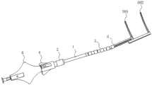
图1为本发明的一种基于柔性杆射频钳子装置整体结构示意图;Fig. 1 is a schematic diagram of the overall structure of a radio frequency pliers device based on flexible rods of the present invention;
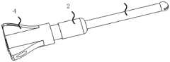
图2为本发明的一种基于柔性杆射频钳子装置中柔性杆结构图;Fig. 2 is a structural diagram of a flexible rod based on a flexible rod radio frequency pliers device of the present invention;
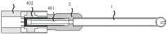
图3为本发明的一种基于柔性杆射频钳子装置中柔性调节旋钮结构示意图;Fig. 3 is a structural schematic diagram of a flexible adjustment knob based on a flexible rod radio frequency pliers device of the present invention;
图4为本发明的一种基于柔性杆射频钳子装置中柔性调节旋钮结构爆炸图;Fig. 4 is an exploded view of the structure of the flexible adjustment knob in the radio frequency pliers device based on the flexible rod of the present invention;
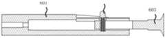
图5为本发明的一种基于柔性杆射频钳子装置中柔性调节旋钮结构剖视图;Fig. 5 is a structural sectional view of a flexible adjustment knob in a radio frequency pliers device based on a flexible rod of the present invention;
图6为本发明的一种基于柔性杆射频钳子装置中夹持作用端结构示意图;Fig. 6 is a schematic diagram of the structure of the clamping end in a radio frequency pliers device based on flexible rods of the present invention;
图7为本发明的一种基于柔性杆射频钳子装置中夹口拉合装置结构示意图;Fig. 7 is a schematic structural diagram of the jaw pulling and closing device based on the flexible rod radio frequency pliers device of the present invention;
图8为本发明的一种基于柔性杆射频钳子装置中夹口拉合装置结构爆炸图;Fig. 8 is an exploded view of the structure of the jaw pulling device in a radio frequency pliers device based on flexible rods of the present invention;
图9为本发明的一种基于柔性杆射频钳子装置中夹口拉合装置结构剖视图;Fig. 9 is a cross-sectional view of the structure of a jaw pulling device based on a flexible rod radio frequency pliers device of the present invention;
其中:1、直杆,2、固定凸台,3、柔性杆,301、柱形铰链,302、球形铰链,4、柔性调节旋钮,401、旋转螺栓,402、棘轮螺母,403、旋柄,5、夹持作用端,501、下夹口,502、上夹口,503、归位弹簧,6、夹口拉合装置,601、握柄,602、定位孔,603、拉杆,604、归位按钮。Among them: 1. Straight rod, 2. Fixed boss, 3. Flexible rod, 301. Cylindrical hinge, 302. Spherical hinge, 4. Flexible adjustment knob, 401. Rotating bolt, 402. Ratchet nut, 403. Rotary handle, 5. Clamping action end, 501, lower jaw, 502, upper jaw, 503, return spring, 6, jaw pulling device, 601, handle, 602, positioning hole, 603, pull rod, 604, return button.
具体实施方式Detailed ways
下面结合附图对本发明的实施方式作进一步说明。Embodiments of the present invention will be further described below in conjunction with the accompanying drawings.
参见附图1,本发明的一种基于柔性杆3射频钳子装置包括:Referring to accompanying drawing 1, a kind of radio frequency pliers device based on flexible rod 3 of the present invention comprises:
刚性的直杆1;rigid
一端和所述直杆1的一端连接的柔性杆3;A flexible rod 3 with one end connected to one end of the
一端通过固定凸台2和所述直杆1另一端连接的柔性调节旋钮4,通过所述柔性调节旋钮4对调节方向和角度后的柔性杆3状态进行固定;One end is connected to the
设置在所述柔性杆3另一端的夹持作用端5;A clamping
以及设置在所述柔性调节旋钮4另一端的夹口拉合装置6,通过所述夹口拉合装置6带动所述夹持作用端5夹持或松开。And the
参见附图2,所述柔性杆3包括多个柱形铰链301和多个球形铰链302,多个所述柱形铰链301和多个所述球形铰链302依次交错铰接。Referring to FIG. 2 , the flexible rod 3 includes a plurality of
参见附图3-附图5,所述柔性调节旋钮4包括:Referring to accompanying drawings 3-5, the
设置在所述固定凸台2内部并相对固定凸台2内部滑动配合的旋转螺栓401,The
柔性夹紧钢丝,所述柔性夹紧钢丝一端和所述旋转螺栓401内孔连接,另一端穿过固定凸台2、直杆1以及柔性杆3内通道后和所述夹持作用端5的固定端连接;Flexible clamping steel wire, one end of the flexible clamping steel wire is connected to the inner hole of the
和所述旋转螺栓401配合的棘轮螺母402;A
以及设置在所述固定凸台2一端外部的旋柄403,所述旋柄403和所述固定凸台2端部转动配合,所述旋柄403与所述棘轮螺母402固定连接。And a
参见附图6,所述夹持作用端5包括:Referring to accompanying drawing 6, the clamping
和柔性杆3端部连接的下夹口501,所述下夹口501包括下调整段和与下调整段一端垂直固定连接的下夹板;A
上夹口502,所述上夹口502包括和所述下夹口501的下调整段滑动配合的上调整段以及和所述上调整段一端垂直固定连接的上夹板,所述上夹板和所述下夹板相对设置;The
以及归位弹簧503,所述归位弹簧503位于所述下调整段内,所述归位弹簧503一端和所述下调整段靠近柔性杆3一端接触,另一端和所述上调整段接触,所述归位弹簧503自然长度时,上夹板相对下夹板分开。上调整段相对所述下调整段运动对归位弹簧503施加压力。通过所述夹口拉合装置6带动所述上夹口502相对下夹口501夹紧或松开。And the
参见附图7-附图9,所述夹口拉合装置6包括:Referring to accompanying drawing 7-accompanying drawing 9, described clamping
一端和所述柔性调节旋钮4另一端连接的握柄601,所述握柄601内部设置有沿射频钳长度方向的通孔;A
和所述握柄601的通孔末端滑动配合拉杆603所述拉杆603相对所述握柄601拉出或收回,进而带动所述夹持作用端5的上夹口502相对下夹口501夹紧或松开;Slidingly cooperate with the end of the through hole of the
夹口夹紧钢丝,所述夹口夹紧钢丝一端和所述拉杆603的一端固定连接,另一端依次穿过柔性调节旋钮4、固定凸台2、直杆1和柔性杆3的内通道后和所述上夹口502连接;The jaw clamps the steel wire, one end of the jaw clamping steel wire is fixedly connected to one end of the
以及锁紧装置,通过所述锁紧装置对拉杆603相对握柄601拉出极限状态时锁紧。And a locking device, through which the
所述锁紧装置包括:The locking device includes:
在所述握柄601末端一侧设置的和所述通孔垂直并连通的定位孔602;A
设置在所述拉杆603上沿长度方向设置的调节孔;An adjustment hole provided on the
设置在调节孔内和所述调节孔滑动配合的归位按钮604,所述归位按钮604相对所述调节孔一端伸出或缩回,所述归为按钮另一端位于所述拉杆603的调节孔内;A
以及锁紧弹簧,所述锁紧弹簧和所述归位弹簧503同轴设置,所述锁紧弹簧一端和所述调节孔的内表面接触,另一端和所述归位按钮604内孔孔底接触,通过所述锁紧弹簧的弹力带动所述归位按钮604在到达定位孔602位置时弹出或缩回。And the locking spring, the locking spring and the
为了避免拉杆603在拉动过程中相对握柄601的通孔发生转动而导致归位按钮604无法在到达定位孔602位置时弹出,可以将拉杆603和通孔之间设置滑道,避免旋转,还可以在拉杆603和通孔之间设置有定位面,避免旋转。In order to prevent the
当上夹口502和下夹口501拉到极限位置时,归位按钮604会在锁紧弹簧作用下向上从调节孔及定位孔602顶出,使拉杆603偏离原来滑动轨道,从而达到锁住拉杆603作用,按下按钮,上夹口502和下夹口501会在归位弹簧的作用下自动归位。When the
柔性杆3的柔性夹紧钢丝首端与下夹口501固定相连,外套橡胶套,穿过柱形铰链301与球形铰链302组成的柔性杆3和直杆1的固定凸台2到达旋转螺栓401末端;上夹口502和下夹口501夹紧钢丝首端与上夹口502末端固定相连,穿过柔性杆3,直杆1的固定凸台2,柔性调节旋钮4最终与拉杆603首端固定相连。两根钢丝在内部走同一通道,但是其首末端都不在同一结构件上,因此两钢丝之间干涉作用极小。The first end of the flexible clamping steel wire of the flexible rod 3 is fixedly connected with the
本发明一种基于柔性杆3射频钳子装置操作方法包括以下步骤:An operating method of a radio frequency pliers device based on a flexible rod 3 of the present invention comprises the following steps:
1)医师将夹口调整至合适方向和角度,旋转柔性调节旋钮4,其中柔性杆33的柔性夹紧钢丝在棘轮螺母402和旋转螺栓401的螺纹配合下被拉紧,从而柱形铰链301301和球形铰链302得到固定,起到固定夹口方向和角度的作用;1) The doctor adjusts the jaw to a suitable direction and angle, and rotates the
2)夹口方向和角度固定后,医师手握握柄601向后方拉动拉杆603,上夹口502和拉杆603首端通过夹口夹紧钢丝连接,因此拉动拉杆603时,上夹口502靠近下夹口501方向移动,起到夹持的作用;2) After the clamp direction and angle are fixed, the doctor holds the
3)当上夹口502和下夹口501拉到极限位置时,归位按钮604会在锁紧弹簧作用下向上顶出,使拉杆603偏离原来滑动轨道,从而达到锁住拉杆603作用,按下归位按钮604,上夹口502和下夹口501会在夹口归位弹簧的作用下自动归位。3) When the
Claims (6)
Priority Applications (1)
| Application Number | Priority Date | Filing Date | Title |
|---|---|---|---|
| CN202211396372.1ACN115670638A (en) | 2022-11-09 | 2022-11-09 | A Flexible Rod-Based Radio Frequency Pliers Device |
Applications Claiming Priority (1)
| Application Number | Priority Date | Filing Date | Title |
|---|---|---|---|
| CN202211396372.1ACN115670638A (en) | 2022-11-09 | 2022-11-09 | A Flexible Rod-Based Radio Frequency Pliers Device |
Publications (1)
| Publication Number | Publication Date |
|---|---|
| CN115670638Atrue CN115670638A (en) | 2023-02-03 |
Family
ID=85049184
Family Applications (1)
| Application Number | Title | Priority Date | Filing Date |
|---|---|---|---|
| CN202211396372.1APendingCN115670638A (en) | 2022-11-09 | 2022-11-09 | A Flexible Rod-Based Radio Frequency Pliers Device |
Country Status (1)
| Country | Link |
|---|---|
| CN (1) | CN115670638A (en) |
Citations (7)
| Publication number | Priority date | Publication date | Assignee | Title |
|---|---|---|---|---|
| US4949927A (en)* | 1989-10-17 | 1990-08-21 | John Madocks | Articulable column |
| US5354297A (en)* | 1992-02-14 | 1994-10-11 | Boaz Avitall | Biplanar deflectable catheter for arrhythmogenic tissue ablation |
| US5910129A (en)* | 1996-12-19 | 1999-06-08 | Ep Technologies, Inc. | Catheter distal assembly with pull wires |
| US6083222A (en)* | 1995-02-28 | 2000-07-04 | Boston Scientific Corporation | Deflectable catheter for ablating cardiac tissue |
| CN102228391A (en)* | 2011-07-13 | 2011-11-02 | 上海交通大学医学院附属新华医院 | Radio-frequency ablation clamp and application thereof |
| CN103054543A (en)* | 2012-12-24 | 2013-04-24 | 上海圣博艾医疗科技有限公司 | Endoscope with adjustable hardness |
| US20130131592A1 (en)* | 2011-11-18 | 2013-05-23 | Thomas V. Selkee | Medical device control handle with independent self holding puller wire actuators |
- 2022
- 2022-11-09CNCN202211396372.1Apatent/CN115670638A/enactivePending
Patent Citations (7)
| Publication number | Priority date | Publication date | Assignee | Title |
|---|---|---|---|---|
| US4949927A (en)* | 1989-10-17 | 1990-08-21 | John Madocks | Articulable column |
| US5354297A (en)* | 1992-02-14 | 1994-10-11 | Boaz Avitall | Biplanar deflectable catheter for arrhythmogenic tissue ablation |
| US6083222A (en)* | 1995-02-28 | 2000-07-04 | Boston Scientific Corporation | Deflectable catheter for ablating cardiac tissue |
| US5910129A (en)* | 1996-12-19 | 1999-06-08 | Ep Technologies, Inc. | Catheter distal assembly with pull wires |
| CN102228391A (en)* | 2011-07-13 | 2011-11-02 | 上海交通大学医学院附属新华医院 | Radio-frequency ablation clamp and application thereof |
| US20130131592A1 (en)* | 2011-11-18 | 2013-05-23 | Thomas V. Selkee | Medical device control handle with independent self holding puller wire actuators |
| CN103054543A (en)* | 2012-12-24 | 2013-04-24 | 上海圣博艾医疗科技有限公司 | Endoscope with adjustable hardness |
Similar Documents
| Publication | Publication Date | Title |
|---|---|---|
| US20200100789A1 (en) | Left atrial appendage devices and methods | |
| CN204797948U (en) | Pin type pincers | |
| CN112568971B (en) | Interatrial septum ostomy device | |
| WO2016005902A1 (en) | Left atrial appendage closure | |
| CN109820561B (en) | A stepless hemostatic forceps | |
| CN209186798U (en) | Adjustable suture lock knot device | |
| CN117159225A (en) | Controllable rotatory valve clamping device | |
| WO2018228432A1 (en) | Multifunctional fracture resetting and guiding forceps | |
| CN115670638A (en) | A Flexible Rod-Based Radio Frequency Pliers Device | |
| CN109091204B (en) | Surgical operation subcutaneous tissue separation minimally invasive scalpel with blade convenient to replace | |
| CN212490068U (en) | Endoscopic appendectomy is with cutting integrative device | |
| CN114788730B (en) | An epicardial ablation system | |
| CN209863991U (en) | Uterine manipulator capable of reducing compression area on uterus | |
| CN114027913B (en) | Left auricle and heart external cerclage system for adsorption type cardiac surgery | |
| CN219021515U (en) | Electrode chuck assembly for pulse ablation device | |
| CN211325398U (en) | Tumor stripping device for gynecological tumor operation | |
| CN216358578U (en) | Peritoneoscope electrocoagulation operation forceps head | |
| CN114748115A (en) | Spine joint spreader for minimally invasive surgery | |
| CN113180761A (en) | Handle part of endoscopic surgery anastomat with single-hand operation retreating mechanism | |
| CN208784899U (en) | Rib rongeur set for thoracoscopy | |
| CN217510564U (en) | Disposable circumcision suturing device for prepuce operation | |
| CN220735464U (en) | Surgical grasping forceps handle with lock | |
| WO2010049862A1 (en) | Endoscopic surgery device | |
| CN113317869A (en) | Closed locking device suitable for surgical electrode and using method thereof | |
| CN120549578A (en) | Puncture-resistant non-destructive grasping forceps for minimally invasive surgery and use method thereof |
Legal Events
| Date | Code | Title | Description |
|---|---|---|---|
| PB01 | Publication | ||
| PB01 | Publication | ||
| SE01 | Entry into force of request for substantive examination | ||
| SE01 | Entry into force of request for substantive examination |