CN115670553A - Rivet pushing device - Google Patents
Rivet pushing deviceDownload PDFInfo
- Publication number
- CN115670553A CN115670553ACN202211705736.XACN202211705736ACN115670553ACN 115670553 ACN115670553 ACN 115670553ACN 202211705736 ACN202211705736 ACN 202211705736ACN 115670553 ACN115670553 ACN 115670553A
- Authority
- CN
- China
- Prior art keywords
- anchor
- puncture
- pushing
- pushing device
- push
- Prior art date
- Legal status (The legal status is an assumption and is not a legal conclusion. Google has not performed a legal analysis and makes no representation as to the accuracy of the status listed.)
- Granted
Links
Images


Landscapes
- Surgical Instruments (AREA)
Abstract
Description
Translated fromChinese技术领域technical field
本发明涉及医疗器械领域,特别涉及一种锚钉推送装置。The invention relates to the field of medical devices, in particular to an anchor pushing device.
背景技术Background technique
腹腔镜手术是一门新发展起来的微创方法,腹腔镜手术传统方法是插入一个叫做戳卡的管道状工作通道,以后一切操作均通过这个管道进行;再用特制的加长手术器械在视频监视下完成与开放手术同样的步骤,达到同样的手术效果。同时在手术过程中为了提升手术操作空间,还需要对一些组织需要进行提拉或者定位。通常采用腹腔镜手术进行腹腔或胸腔手术治疗时, 一般需要先设置出1~5个直径为5~15mm贯穿腹(胸)壁全层的穿刺通道,使腹腔镜和手术器械能够从这些穿刺通道进入腹腔或胸腔实施手术,手术结束拔除"戳卡"和手术器械后,须对这些穿刺通道进行缝合,以便伤口痊愈。目前对腹腔或胸腔壁穿刺通道的缝合采用的缝合针均为弯曲的缝针,但穿刺孔相对较小,操作起来就十分困难,致使直径相对较小的穿刺通道往往不易缝合,有时会因为缝合不完善而发生术后出血、伤口愈合不良,或可诱发感染,甚至造成腹壁疝,给病人带来很大痛苦。Laparoscopic surgery is a newly developed minimally invasive method. The traditional method of laparoscopic surgery is to insert a tube-shaped working channel called poking card, and all operations will be performed through this channel; Complete the same steps as open surgery to achieve the same surgical effect. At the same time, in order to improve the operating space during the operation, some tissues need to be lifted or positioned. Usually, when laparoscopic surgery is used for abdominal or thoracic surgery, it is generally necessary to set up 1 to 5 puncture channels with a diameter of 5 to 15 mm through the entire abdominal (chest) wall, so that laparoscope and surgical instruments can pass through these puncture channels. Enter the abdominal cavity or thoracic cavity to perform surgery. After the operation is completed and the "poke card" and surgical instruments are removed, these puncture channels must be sutured to allow the wound to heal. At present, the suture needles used for suturing the puncture channels of the abdominal cavity or thoracic wall are all curved needles, but the puncture holes are relatively small, and it is very difficult to operate. If it is not perfect, postoperative bleeding and poor wound healing may occur, or it may induce infection, and even cause abdominal hernia, which brings great pain to the patient.
发明内容Contents of the invention
本发明要解决的是现有技术中穿刺通道缝合不良的技术问题。The present invention aims to solve the technical problem of poor suturing of puncture channels in the prior art.
为解决上述技术问题,本发明提供的技术方案如下:In order to solve the problems of the technologies described above, the technical solutions provided by the invention are as follows:
一种锚钉推送装置,包括:锚钉部件、推送部件、穿刺部件;锚钉部件包括锚钉和缝线,缝线的一端固定在锚钉上;穿刺部件包括穿刺针,推送部件包括中空通道,穿刺部件从中空通道穿过,锚钉套装在穿刺针前端;其中,穿刺部件用于刺穿组织后将锚钉送入体内,推送部件用于将锚钉从穿刺针前端脱离,从而实现锚钉的埋置。An anchor pushing device, comprising: an anchor component, a pushing component, and a puncture component; the anchor component includes an anchor and a suture, and one end of the suture is fixed on the anchor; the puncture component includes a puncture needle, and the pushing component includes a hollow channel , the puncture part passes through the hollow channel, and the anchor is set on the front end of the puncture needle; wherein, the puncture part is used to puncture the tissue and send the anchor into the body, and the pushing part is used to detach the anchor from the front end of the puncture needle, so as to realize the anchor Nail embedding.
进一步地,穿刺针前端设有环形槽,锚钉设有环形内台,环形槽与环形内台配合卡位。Further, the front end of the puncture needle is provided with an annular groove, and the anchor is provided with an annular inner platform, and the annular groove and the annular inner platform are engaged and locked.
进一步地,穿刺针设有三角刃,锚钉设有圆锥面。Further, the puncture needle is provided with a triangular edge, and the anchor is provided with a conical surface.
进一步地,锚钉推送装置包括上手柄外壳和下手柄外壳,穿刺部件与上手柄外壳固定;推送部件包括推送管、推送块,推送管与推送块固定连接;推送部件套有压簧,压簧一端与推送块设有的圆台接触,整体装入上手柄外壳。Further, the anchor pushing device includes an upper handle shell and a lower handle shell, and the puncture part is fixed to the upper handle shell; the push part includes a push tube and a push block, and the push tube is fixedly connected to the push block; the push part is covered with a compression spring, and the compression spring One end is in contact with the round platform provided on the push block, and is integrally put into the upper handle shell.
进一步地,锚钉推送装置还包括释放推杆,按动释放推杆,会推动推送部件使锚钉部件与穿刺针部件分离脱落。Further, the anchor pushing device further includes a release push rod, which pushes the push part to separate the anchor part from the puncture needle part when the release push rod is pressed.
进一步地,释放推杆设有限位台阶与下手柄外壳设有的导向槽配合,限制释放推杆旋转以及对轴向运动行程限位。Further, the release push rod is provided with a limit step that cooperates with the guide groove provided on the lower handle shell to limit the rotation of the release push rod and limit the travel of the axial movement.
进一步地,释放推杆设有保险部件,保险部件用于对推送部件进行位置锁定。Further, the release push rod is provided with a safety component, which is used to lock the position of the push component.
进一步地,保险部件包括保险勾,按压释放推杆后保险勾与上手柄外壳设有的保险卡位台咬合,实现推送部件位置锁定;再次使用时,按动保险勾,在压簧弹力作用下使推送部件回复初始位置,裸露出穿刺针设有的三角刃,装入锚钉部件,可继续推送锚钉部件至预期位置。Further, the safety part includes a safety hook, and after pressing and releasing the push rod, the safety hook engages with the safety card position platform provided on the upper handle shell to realize the position locking of the pushing part; The pushing part is returned to the initial position, the triangular edge provided with the puncture needle is exposed, the anchor part is loaded, and the anchor part can be continuously pushed to the expected position.
进一步地,锚钉部件采用可生物降解材质制成。Further, the anchor part is made of biodegradable material.
采用这样的设计后,本发明至少具有以下优点:After adopting such design, the present invention has the following advantages at least:
(1)锚钉推送操作方便,通过牵拉锚钉上设有的缝线可以对组织进行牵拉与缝合,节省手术时间。(2)锚钉与组织的接触面积大大增加,在牵拉缝线过程中,可以减少应力对组织的再次损伤,有利于病人后期恢复减少疼痛。(3)在完成推送锚钉后,推送管锁止可以保护针尖,避免因针尖裸露造成的二次伤害。(4)推送装置在同台手术解锁后可以再次使用。(5)本发明结构简单,效果好,且成本低,易工艺实现。(1) The push operation of the anchor is convenient, and the tissue can be pulled and sutured by pulling the suture provided on the anchor, saving operation time. (2) The contact area between the anchor and the tissue is greatly increased. During the process of pulling the suture, it can reduce the re-damage of the tissue by the stress, which is beneficial to the patient's later recovery and reduces pain. (3) After the anchor is pushed, the locking of the push tube can protect the needle tip and avoid secondary injury caused by the exposed needle tip. (4) The push device can be used again after being unlocked during the same surgery. (5) The present invention has simple structure, good effect, low cost and easy technological realization.
附图说明Description of drawings
上述仅是本发明技术方案的概述,为了能够更清楚了解本发明的技术手段,以下结合附图与具体实施方式对本发明作进一步的详细说明。The above is only an overview of the technical solution of the present invention. In order to better understand the technical means of the present invention, the present invention will be further described in detail below in conjunction with the accompanying drawings and specific embodiments.
图1是本发明锚钉推送装置的分解示意图;Fig. 1 is an exploded schematic view of the anchor pushing device of the present invention;
图2是本发明的穿刺针部件立体结构示意图;Fig. 2 is a schematic diagram of the three-dimensional structure of the puncture needle part of the present invention;
图3是本发明的推送部件立体结构示意图;Fig. 3 is a schematic diagram of the three-dimensional structure of the pushing part of the present invention;
图4是本发明的锚钉部件立体结构示意图;Fig. 4 is a schematic diagram of the three-dimensional structure of the anchor component of the present invention;
图5是本发明的锚钉剖面结构示意图;Fig. 5 is a schematic diagram of the cross-sectional structure of the anchor of the present invention;
图6是本发明的上手柄外壳立体结构示意图;Fig. 6 is a schematic diagram of the three-dimensional structure of the upper handle shell of the present invention;
图7是本发明的下手柄外壳立体结构示意图;Fig. 7 is a schematic diagram of the three-dimensional structure of the lower handle shell of the present invention;
图8是本发明的锚钉推送装置推送完成状态剖面示意图;Fig. 8 is a schematic cross-sectional view of the pushing completion state of the anchor pushing device of the present invention;
图9是本发明的应用引导管立体结构示意图;9 is a schematic diagram of the three-dimensional structure of the application guide tube of the present invention;
图10是本发明的应用筋膜缝合示意图;Fig. 10 is a schematic diagram of the application of fascial suture in the present invention;
图11是本发明的应用组织悬吊刺穿示意图;Fig. 11 is a schematic diagram of tissue suspension puncture applied in the present invention;
图12是本发明的应用组织悬吊示意图;Fig. 12 is a schematic diagram of the application tissue suspension of the present invention;
附图标记, 100上手柄外壳、101保险卡位台、102固定槽、103卡位台阶、104导轨台、105定位柱、200下手柄外壳、201导向槽、202内六角孔、300释放推杆、301保险勾、302限位台阶、400穿刺部件、410定位块、411定位凸台、420穿刺针、421三角刃、422环形槽、500推送部件、510推送管、520推送块、521中空通道、522圆台、523开口槽、600压簧、700锚钉部件、710锚钉、711锚钉环形槽、712圆锥面、713环形内台、720缝线、800引导管、801倒扣、802斜向通道。Reference numerals, 100 upper handle shell, 101 safety card position platform, 102 fixed groove, 103 card position step, 104 guide rail platform, 105 positioning column, 200 lower handle shell, 201 guide groove, 202 inner hexagonal hole, 300 release push rod , 301 safety hook, 302 limit step, 400 puncture part, 410 positioning block, 411 positioning boss, 420 puncture needle, 421 triangular edge, 422 annular groove, 500 pushing part, 510 pushing tube, 520 pushing block, 521 hollow channel , 522 round platform, 523 open slot, 600 compression spring, 700 anchor component, 710 anchor, 711 anchor annular groove, 712 conical surface, 713 annular inner platform, 720 suture, 800 guide tube, 801 undercut, 802 oblique to the channel.
具体实施方式Detailed ways
下面将结合本发明实施例中的附图,对本发明实施例中的技术方案进行清楚、完整的描述,显然,所描述的实施例仅仅是本发明一部分实施例,而不是全部的实施例。基于本发明中的实施例,本领域普通技术人员在没有作出创造性劳动前提下所获得的所有其他实施例,都属于本发明保护的范围。The technical solutions in the embodiments of the present invention will be clearly and completely described below in conjunction with the accompanying drawings in the embodiments of the present invention. Obviously, the described embodiments are only some, not all, embodiments of the present invention. Based on the embodiments of the present invention, all other embodiments obtained by persons of ordinary skill in the art without creative efforts fall within the protection scope of the present invention.
在本文中,“上”、“下”等仅用于表示相关部分之间的相对位置关系,而非限定这些相关部分的绝对位置。Herein, "upper", "lower" and the like are only used to indicate the relative positional relationship between related parts, rather than to limit the absolute positions of these related parts.
以下每个部件靠近操作者的一端定义为近端,远离操作者的一端定义为远端。该近端、远端的表达只用于使描述简单、清楚,不应该理解为对本发明的任何限定。The end of each of the following components close to the operator is defined as the proximal end, and the end far away from the operator is defined as the distal end. The expressions of proximal end and distal end are only used to make the description simple and clear, and should not be construed as any limitation to the present invention.
参见附图1-4,一种锚钉推送装置,包括:锚钉部件700、推送部件500、穿刺部件400;锚钉部件包括锚钉710和缝线720,缝线720的一端固定在锚钉710上;穿刺部件400包括穿刺针420,推送部件500包括中空通道521,穿刺部件400从中空通道521穿过,锚钉710套装在穿刺针420前端;其中,穿刺部件用于刺穿组织后将锚钉送入体内,推送部件用于将锚钉从穿刺针前端脱离,从而实现锚钉的埋置。优选地,缝线720一端拴在锚钉710中部设有的锚钉环形槽711内固定。Referring to accompanying drawings 1-4, an anchor pushing device includes: an
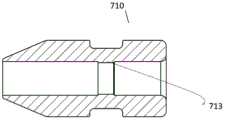
参见附图2、5,穿刺针420设有环形槽422,锚钉710设有环形内台713,环形槽422与环形内台713配合卡位,从而避免锚钉710从穿刺针420意外脱出。进一步地,穿刺针420设有三角刃421,三角刃421更利于穿过腹壁组织A与筋膜层等坚韧组织,锚钉710设有圆锥面712,在三角刃421刺穿过腹壁组件A或腹腔组织B时,圆锥面712可以更好导向穿过。Referring to Figures 2 and 5, the
参见附图1-3、6,进一步地,锚钉推送装置包括上手柄外壳100和下手柄外壳200,推送部件包括推送管510、推送块520,推送管510与推送块520固定连接;推送部件500套有压簧600,压簧600一端与推送块520设有的圆台522接触,整体装入上手柄外壳100;穿刺部件与上手柄外壳固定。Referring to accompanying drawings 1-3 and 6, further, the anchor pushing device includes an
具体地,上手柄外壳100设有固定槽102,穿刺部件包括定位块410,定位块410与穿刺针420通过镶嵌注塑或粘合等方式固定连接,定位块410上设有定位凸台411,固定凹槽102与定位块410设有的定位凸台411配合,使得穿刺针部件400相对上手柄外壳100固定。推送块520设有开口槽523与上手柄外壳100设有的导轨台104配合,限制推送部件500相对上手柄外壳100圆周的旋转,只可以做轴向往复运动。压簧600另一端压在上手柄外壳100设有的卡位台阶103上。下手柄外壳200设有内六角孔202与上手柄外壳100设有的定位柱105过盈配合。Specifically, the
参见附图1、6-8,锚钉推送装置还包括释放推杆300,按动释放推杆300,会推动推送部件500使锚钉部件700与穿刺针部件400分离脱落,从而实现锚钉部710的埋置。释放推杆300安装于上手柄外壳100另一侧,释放推杆300设有限位台阶302与下手柄外壳200设有的导向槽201配合,限制释放推杆300旋转以及对轴向运动行程限位。进一步地,释放推杆300设有保险部件,保险部件用于对推送部件进行位置锁定,具体地,保险部件包括保险勾301,按压释放推杆300后保险勾301与上手柄外壳100设有的保险卡位台101咬合,实现推送部件500位置锁定,穿刺针420完全进入推送部件500内,可以杜绝穿刺针420对组织或医护人员的误伤。再次使用时,按动保险勾301,在压簧600弹力作用下使推送部件500回复初始位置,裸露出穿刺针420设有的三角刃421,装入锚钉部件700,可继续推送锚钉部件700至预期位置。Referring to accompanying drawings 1, 6-8, the anchor pushing device also includes a
参见附图9-10,引导管800设有倒扣801和均匀分布多个斜向通道,优选地,斜向通道802为4个。在缝合腹壁组织A戳卡孔时,插入引导管800,引导管800设有的倒扣801增强与戳卡孔的摩擦力提高固定稳定性。分别在斜向通道802插入锚钉推送装置,至少植入两个锚钉部件700后拔出引导管800而后打结缝线720即可完成缝合。优选地,锚钉部件700采用可生物降解材质制成,减少后期患者因拆除缝线带来的疼痛。Referring to Figures 9-10, the
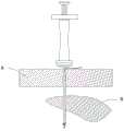
参见附图11-12,锚钉推送装置穿过腹壁组织A与腹腔组织B,埋置锚钉部件700后,通过牵拉缝线720即可悬吊起需要牵拉的组织。Referring to Figures 11-12 , the anchor pushing device passes through the abdominal wall tissue A and the abdominal cavity tissue B, and after embedding the
本领域技术人员在考虑说明书及实施例公开的发明后,将容易想到本发明的其它实施方案。本申请旨在涵盖本发明的任何变型、用途或者适应性变化,这些变型、用途或者适应性变化遵循本发明的一般性原理并包括本发明未公开的本技术领域中的公知常识或惯用技术手段。说明书和实施例仅被视为示例性的。Other embodiments of the invention will readily occur to those skilled in the art from consideration of the invention disclosed in the specification and examples. This application is intended to cover any modification, use or adaptation of the present invention, these modifications, uses or adaptations follow the general principles of the present invention and include common knowledge or conventional technical means in the technical field not disclosed in the present invention . The specification and examples are to be considered as illustrative only.
应当理解的是,本发明并不局限于上面已经描述并在附图中示出的精确结构,并且可以在不脱离其范围进行各种修改和改变。本发明的范围仅由所附的权利要求来限制。It should be understood that the present invention is not limited to the precise constructions which have been described above and shown in the accompanying drawings, and various modifications and changes may be made without departing from the scope thereof. The scope of the invention is limited only by the appended claims.
Claims (9)
Translated fromChinesePriority Applications (1)
| Application Number | Priority Date | Filing Date | Title |
|---|---|---|---|
| CN202211705736.XACN115670553B (en) | 2022-12-29 | 2022-12-29 | Anchor nail pushing device |
Applications Claiming Priority (1)
| Application Number | Priority Date | Filing Date | Title |
|---|---|---|---|
| CN202211705736.XACN115670553B (en) | 2022-12-29 | 2022-12-29 | Anchor nail pushing device |
Publications (2)
| Publication Number | Publication Date |
|---|---|
| CN115670553Atrue CN115670553A (en) | 2023-02-03 |
| CN115670553B CN115670553B (en) | 2023-06-13 |
Family
ID=85056529
Family Applications (1)
| Application Number | Title | Priority Date | Filing Date |
|---|---|---|---|
| CN202211705736.XAActiveCN115670553B (en) | 2022-12-29 | 2022-12-29 | Anchor nail pushing device |
Country Status (1)
| Country | Link |
|---|---|
| CN (1) | CN115670553B (en) |
Cited By (1)
| Publication number | Priority date | Publication date | Assignee | Title |
|---|---|---|---|---|
| CN117618083A (en)* | 2023-11-29 | 2024-03-01 | 瀚芯医疗科技(深圳)有限公司 | Puncture anchoring device |
Citations (8)
| Publication number | Priority date | Publication date | Assignee | Title |
|---|---|---|---|---|
| US20080208220A1 (en)* | 2007-02-27 | 2008-08-28 | Olympus Medical Systems Corporation | Suture instrument |
| JP2010273933A (en)* | 2009-05-29 | 2010-12-09 | Hoya Corp | Suturing device for endoscope |
| CN101999916A (en)* | 2010-09-28 | 2011-04-06 | 常州市康迪医用吻合器有限公司 | Endoscopic surgery cutting stapler with elastic neck ring |
| CN102228385A (en)* | 2010-07-06 | 2011-11-02 | 北京中法派尔特医疗设备有限公司 | Circular purse string clamp |
| CN103654895A (en)* | 2012-09-26 | 2014-03-26 | 德普伊米特克有限责任公司 | Anchor Inserter |
| CN108158635A (en)* | 2016-12-07 | 2018-06-15 | 英特姆(武汉)医疗科技有限公司 | Puncture needle and wound closure device |
| CN112869797A (en)* | 2021-03-16 | 2021-06-01 | 上海竞微扶生医学科技有限公司 | Conveyor, wire passing device, tunnel type wire passing system and operation method thereof |
| CN114601518A (en)* | 2022-03-15 | 2022-06-10 | 海南维智博威鑫科技有限公司 | a fascia closure |
- 2022
- 2022-12-29CNCN202211705736.XApatent/CN115670553B/enactiveActive
Patent Citations (8)
| Publication number | Priority date | Publication date | Assignee | Title |
|---|---|---|---|---|
| US20080208220A1 (en)* | 2007-02-27 | 2008-08-28 | Olympus Medical Systems Corporation | Suture instrument |
| JP2010273933A (en)* | 2009-05-29 | 2010-12-09 | Hoya Corp | Suturing device for endoscope |
| CN102228385A (en)* | 2010-07-06 | 2011-11-02 | 北京中法派尔特医疗设备有限公司 | Circular purse string clamp |
| CN101999916A (en)* | 2010-09-28 | 2011-04-06 | 常州市康迪医用吻合器有限公司 | Endoscopic surgery cutting stapler with elastic neck ring |
| CN103654895A (en)* | 2012-09-26 | 2014-03-26 | 德普伊米特克有限责任公司 | Anchor Inserter |
| CN108158635A (en)* | 2016-12-07 | 2018-06-15 | 英特姆(武汉)医疗科技有限公司 | Puncture needle and wound closure device |
| CN112869797A (en)* | 2021-03-16 | 2021-06-01 | 上海竞微扶生医学科技有限公司 | Conveyor, wire passing device, tunnel type wire passing system and operation method thereof |
| CN114601518A (en)* | 2022-03-15 | 2022-06-10 | 海南维智博威鑫科技有限公司 | a fascia closure |
Cited By (1)
| Publication number | Priority date | Publication date | Assignee | Title |
|---|---|---|---|---|
| CN117618083A (en)* | 2023-11-29 | 2024-03-01 | 瀚芯医疗科技(深圳)有限公司 | Puncture anchoring device |
Also Published As
| Publication number | Publication date |
|---|---|
| CN115670553B (en) | 2023-06-13 |
Similar Documents
| Publication | Publication Date | Title |
|---|---|---|
| US9687226B2 (en) | Wound closure device including mesh barrier | |
| US6387114B2 (en) | Gastrointestinal compression clips | |
| US5683417A (en) | Suture and method for endoscopic surgery | |
| US6893459B1 (en) | Heart valve annulus device and method of using same | |
| US5860990A (en) | Method and apparatus for suturing | |
| US6562052B2 (en) | Suturing device and method | |
| US5779719A (en) | Device and method for the percutaneous suturing of a vascular puncture site | |
| US9468435B2 (en) | Wound closure device | |
| JP2001524864A (en) | A suturing device for sealing an opening in a blood vessel or other biological tissue | |
| US7967741B2 (en) | Endoscopic guide device | |
| US20030167063A1 (en) | Laparoscopic port site fascial closure device | |
| EP2314238B1 (en) | Fixation device for suturing and restoring a temporomandibular joint disc | |
| CA2523791A1 (en) | Surgical instrument for endoscopic suturing of deep subcutaneous tissue | |
| CN112890929A (en) | Abdominal cavity puncture suturing device | |
| CN107898491A (en) | Safety-type puncture core | |
| CN115670553A (en) | Rivet pushing device | |
| CN111374739B (en) | Puncture core assembly and puncture outfit | |
| CN219501081U (en) | Vascular closure device and vascular closure system | |
| CN113520541A (en) | Automatic suture fascia peritoneoscope pjncture needle and puncture ware | |
| CN108261229B (en) | Puncture core subassembly and have its puncture ware | |
| CN212415820U (en) | Hemostatic buckle and sternum suture assembly | |
| CN217066460U (en) | Puncture thread hooking device | |
| CN222681825U (en) | Rivet sleeve assembly device | |
| CN215306503U (en) | Abdominal cavity puncture suturing device | |
| KR200455488Y1 (en) | Intraoperative Suture Knot Fasteners |
Legal Events
| Date | Code | Title | Description |
|---|---|---|---|
| PB01 | Publication | ||
| PB01 | Publication | ||
| SE01 | Entry into force of request for substantive examination | ||
| SE01 | Entry into force of request for substantive examination | ||
| GR01 | Patent grant | ||
| GR01 | Patent grant | ||
| CP03 | Change of name, title or address | ||
| CP03 | Change of name, title or address | Address after:No. 8 Shangcheng Road, Beiqijia Town, Changping District, Beijing 102209 Patentee after:B.J. ZH. F. PANTHER MEDICAL EQUIPMENT Co.,Ltd. Country or region after:China Address before:102200 three floor, 1 floor, 28 torch street, Changping District science and Technology Park, Beijing. Patentee before:B.J. ZH. F. PANTHER MEDICAL EQUIPMENT Co.,Ltd. Country or region before:China |