CN115668033A - Method and system for dual-projector waveguide display with wide field of view - Google Patents
Method and system for dual-projector waveguide display with wide field of viewDownload PDFInfo
- Publication number
- CN115668033A CN115668033ACN202180036347.XACN202180036347ACN115668033ACN 115668033 ACN115668033 ACN 115668033ACN 202180036347 ACN202180036347 ACN 202180036347ACN 115668033 ACN115668033 ACN 115668033A
- Authority
- CN
- China
- Prior art keywords
- region
- waveguide
- view
- light
- icg
- Prior art date
- Legal status (The legal status is an assumption and is not a legal conclusion. Google has not performed a legal analysis and makes no representation as to the accuracy of the status listed.)
- Pending
Links
Images


Classifications
- G—PHYSICS
- G02—OPTICS
- G02B—OPTICAL ELEMENTS, SYSTEMS OR APPARATUS
- G02B27/00—Optical systems or apparatus not provided for by any of the groups G02B1/00 - G02B26/00, G02B30/00
- G02B27/01—Head-up displays
- G02B27/017—Head mounted
- G02B27/0172—Head mounted characterised by optical features
- G—PHYSICS
- G02—OPTICS
- G02B—OPTICAL ELEMENTS, SYSTEMS OR APPARATUS
- G02B27/00—Optical systems or apparatus not provided for by any of the groups G02B1/00 - G02B26/00, G02B30/00
- G02B27/0081—Optical systems or apparatus not provided for by any of the groups G02B1/00 - G02B26/00, G02B30/00 with means for altering, e.g. enlarging, the entrance or exit pupil
- G—PHYSICS
- G02—OPTICS
- G02B—OPTICAL ELEMENTS, SYSTEMS OR APPARATUS
- G02B6/00—Light guides; Structural details of arrangements comprising light guides and other optical elements, e.g. couplings
- G—PHYSICS
- G02—OPTICS
- G02B—OPTICAL ELEMENTS, SYSTEMS OR APPARATUS
- G02B6/00—Light guides; Structural details of arrangements comprising light guides and other optical elements, e.g. couplings
- G02B6/0001—Light guides; Structural details of arrangements comprising light guides and other optical elements, e.g. couplings specially adapted for lighting devices or systems
- G02B6/0011—Light guides; Structural details of arrangements comprising light guides and other optical elements, e.g. couplings specially adapted for lighting devices or systems the light guides being planar or of plate-like form
- G02B6/0013—Means for improving the coupling-in of light from the light source into the light guide
- G02B6/0015—Means for improving the coupling-in of light from the light source into the light guide provided on the surface of the light guide or in the bulk of it
- G—PHYSICS
- G02—OPTICS
- G02B—OPTICAL ELEMENTS, SYSTEMS OR APPARATUS
- G02B6/00—Light guides; Structural details of arrangements comprising light guides and other optical elements, e.g. couplings
- G02B6/0001—Light guides; Structural details of arrangements comprising light guides and other optical elements, e.g. couplings specially adapted for lighting devices or systems
- G02B6/0011—Light guides; Structural details of arrangements comprising light guides and other optical elements, e.g. couplings specially adapted for lighting devices or systems the light guides being planar or of plate-like form
- G02B6/0033—Means for improving the coupling-out of light from the light guide
- G02B6/0035—Means for improving the coupling-out of light from the light guide provided on the surface of the light guide or in the bulk of it
- G02B6/0038—Linear indentations or grooves, e.g. arc-shaped grooves or meandering grooves, extending over the full length or width of the light guide
- G—PHYSICS
- G02—OPTICS
- G02B—OPTICAL ELEMENTS, SYSTEMS OR APPARATUS
- G02B27/00—Optical systems or apparatus not provided for by any of the groups G02B1/00 - G02B26/00, G02B30/00
- G02B27/01—Head-up displays
- G02B27/0101—Head-up displays characterised by optical features
- G02B2027/0123—Head-up displays characterised by optical features comprising devices increasing the field of view
- G02B2027/0125—Field-of-view increase by wavefront division
- G—PHYSICS
- G02—OPTICS
- G02B—OPTICAL ELEMENTS, SYSTEMS OR APPARATUS
- G02B27/00—Optical systems or apparatus not provided for by any of the groups G02B1/00 - G02B26/00, G02B30/00
- G02B27/01—Head-up displays
- G02B27/017—Head mounted
- G02B27/0172—Head mounted characterised by optical features
- G02B2027/0174—Head mounted characterised by optical features holographic
- G—PHYSICS
- G02—OPTICS
- G02B—OPTICAL ELEMENTS, SYSTEMS OR APPARATUS
- G02B27/00—Optical systems or apparatus not provided for by any of the groups G02B1/00 - G02B26/00, G02B30/00
- G02B27/01—Head-up displays
- G02B27/017—Head mounted
- G02B2027/0178—Eyeglass type
Landscapes
- Physics & Mathematics (AREA)
- General Physics & Mathematics (AREA)
- Optics & Photonics (AREA)
- Diffracting Gratings Or Hologram Optical Elements (AREA)
Abstract
Translated fromChinese
Description
Translated fromChinese相关申请的交叉引用Cross References to Related Applications
本申请要求于2020年5月22日提交的题为“METHOD AND SYSTEM FOR DUALPROJECTOR WAVEGUIDE DISPLAYS WITH WIDE FIELD OF VIEW(用于具有宽视场的双投射器波导显示器的方法和系统)”的美国临时专利申请号63/029,312的优先权的权益,其全部内容以其整体通过引用并入本文用于所有目的。This application claims a U.S. provisional patent entitled "METHOD AND SYSTEM FOR DUALPROJECTOR WAVEGUIDE DISPLAYS WITH WIDE FIELD OF VIEW," filed May 22, 2020 The benefit of priority of Application No. 63/029,312, the entire contents of which are hereby incorporated by reference in their entirety for all purposes.
背景技术Background technique
现代计算和显示技术已经促进用于所谓的“虚拟现实”或“增强现实”体验的系统的发展,其中,数字再现的图像或其部分以其看起来是真实的或可以被感知为真实的方式呈现给用户。虚拟现实或者“VR”场景通常涉及在对于其他实际现实世界视觉输入没有透明度的情况下呈现数字或者虚拟图像信息;增强现实或者“AR”场景通常涉及将数字或者虚拟图像信息作为用户周围的实际世界的可视化的增强耳呈现。Modern computing and display technologies have facilitated the development of systems for so-called "virtual reality" or "augmented reality" experiences, in which images, or parts thereof, are digitally reproduced in such a way that they appear real or can be perceived as real presented to the user. Virtual reality or "VR" scenarios typically involve presenting digital or virtual image information without transparency to other actual real-world visual input; augmented reality or "AR" scenarios typically involve digital or virtual image information as part of the actual world around the user. Enhanced ear rendering of the visualization.
尽管在这些显示技术中取得进步,但是在本领域中需要与增强现实系统(特别是显示系统)有关的经改进的方法和系统。Despite the advancements in these display technologies, there is a need in the art for improved methods and systems related to augmented reality systems, particularly display systems.
发明内容Contents of the invention
本发明大体涉及与包括可穿戴显示器的透射显示系统相关的方法和系统。更特别地,本发明的实施例提供了与传统系统相比提供扩展的视场的方法和系统。本发明适用于计算机视觉和图像显示系统中的各种应用。The present invention generally relates to methods and systems related to transmissive display systems including wearable displays. More particularly, embodiments of the present invention provide methods and systems that provide an expanded field of view compared to conventional systems. The invention is applicable to various applications in computer vision and image display systems.
如本文所描述的,通过使用多个投射器来创建形成组合视场的子显示器,目镜波导(也称为目镜)的视场相对于传统设计增加。As described herein, the field of view of an eyepiece waveguide (also referred to as an eyepiece) is increased relative to conventional designs by using multiple projectors to create sub-displays that form a combined field of view.
根据本发明的实施例,提供了一种用于增强现实显示系统的目镜波导。目镜波导包括具有第一表面和第二表面的基板。目镜波导还包括形成在基板的第一表面或第二表面上或基板的第一表面或第二表面中的衍射输入耦合元件。衍射输入耦合元件被配置为接收输入光束并将输入光束耦合到基板中作为引导光束。目镜波导还包括形成在基板的第一表面或第二表面上或基板的第一表面或第二表面中的衍射组合光瞳扩展器-提取器(CPE)元件。衍射CPE元件包括由轴划分的第一部分和第二部分。第一组衍射光学元件设置在第一部分中并以相对于轴的正角度取向,并且第二组衍射光学元件设置在第二部分中并以相对于轴的负角度取向。According to an embodiment of the present invention, an eyepiece waveguide for an augmented reality display system is provided. The eyepiece waveguide includes a substrate having a first surface and a second surface. The eyepiece waveguide also includes a diffractive in-coupling element formed on or in the first or second surface of the substrate. A diffractive in-coupling element is configured to receive an input beam and couple the input beam into the substrate as a guide beam. The eyepiece waveguide also includes a diffractive combining pupil expander-extractor (CPE) element formed on or in the first or second surface of the substrate. The diffractive CPE element includes a first portion and a second portion divided by an axis. A first set of diffractive optical elements is disposed in the first portion and oriented at a positive angle relative to the axis, and a second set of diffractive optical elements is disposed in the second portion and oriented at a negative angle relative to the axis.
根据本发明的另一实施例,提供了一种用于增强现实显示系统的目镜波导。目镜波导包括具有第一表面和第二表面的基板。目镜波导还包括形成在基板的第一表面或第二表面上或基板的第一表面或第二表面中的第一衍射输入耦合元件。第一衍射输入耦合元件被配置为接收第一输入光束并将第一输入光束耦合到基板中作为第一引导光束。目镜波导还包括形成在基板的第一表面或第二表面上或基板的第一表面或第二表面中的第二衍射输入耦合元件。第二衍射输入耦合元件被配置为接收第二输入光束并将第二输入光束耦合到基板中作为第二引导光束。According to another embodiment of the present invention, an eyepiece waveguide for an augmented reality display system is provided. The eyepiece waveguide includes a substrate having a first surface and a second surface. The eyepiece waveguide also includes a first diffractive in-coupling element formed on or in the first or second surface of the substrate. The first diffractive in-coupling element is configured to receive a first input beam and couple the first input beam into the substrate as a first guided beam. The eyepiece waveguide also includes a second diffractive in-coupling element formed on or in the first or second surface of the substrate. The second diffractive in-coupling element is configured to receive a second input beam and couple the second input beam into the substrate as a second guided beam.
此外,目镜波导还包括形成在基板的第一表面或第二表面上或基板的第一表面或第二表面中的衍射组合光瞳扩展器-提取器(CPE)元件。衍射CPE元件被定位为:接收来自第一衍射输入耦合元件的第一引导光束;接收来自第二衍射输入耦合元件的第二引导光束;在第一角度范围内将第一引导光束的至少一部分耦出,以形成组合视场的第一视场;以及在第二角度范围内将第二引导光束的至少一部分耦出,以形成组合视场的第二视场。Additionally, the eyepiece waveguide includes a diffractive combining pupil expander-extractor (CPE) element formed on or in the first or second surface of the substrate. The diffractive CPE element is positioned to: receive the first directed beam from the first diffractive in-coupling element; receive the second directed beam from the second diffractive in-coupling element; couple at least a portion of the first directed beam within a first angular range outcoupling to form a first field of view of the combined field of view; and outcoupling at least a portion of the second directed light beam within a second range of angles to form a second field of view of the combined field of view.
根据本发明的具体实施例,提供了一种设置在眼镜中的波导显示器。波导显示器包括第一投射器、第二投射器、光学耦合到第一投射器的第一耦入光栅(ICG),以及光学耦合到第二投射器的第二ICG。轴穿过第一ICG和第二ICG。波导显示器还包括光学耦合到第一ICG并且包括第一部分和第二部分的第一衍射区域,该第一部分包括以相对于轴的正角度取向的第一组光栅,并且该第二部分包括以相对于轴的负角度取向的第二组光栅。波导显示器还包括光学耦合到第二ICG并且包括第一部分和第二部分的第二衍射区域,该第一部分包括以相对于轴的180°减去所述正角度取向的第三组光栅,并且该第二部分包括以-相对于轴的180°减去所述负角度取向的第四组光栅。According to a specific embodiment of the present invention, a waveguide display arranged in glasses is provided. The waveguide display includes a first projector, a second projector, a first in-coupling grating (ICG) optically coupled to the first projector, and a second ICG optically coupled to the second projector. The axis passes through the first ICG and the second ICG. The waveguide display also includes a first diffractive region optically coupled to the first ICG and comprising a first portion comprising a first set of gratings oriented at a positive angle relative to the axis and a second portion comprising a first set of gratings oriented at an opposite A second set of gratings oriented at a negative angle to the axis. The waveguide display also includes a second diffractive region optically coupled to the second ICG and comprising a first portion comprising a third set of gratings oriented at 180° to the axis minus said positive angle and a second portion, and the The second part includes a fourth set of gratings oriented at -180° relative to the axis minus the negative angle.
根据本发明的特定实施例,提供了一种操作由第一区域和第二区域限定的目镜波导的方法。方法包括导引来自第一投射器的光以入射在第一耦入光栅(ICG)上。方法还包括将来自第一投射器的光的一部分衍射到目镜波导的第一区域的第一部分中、衍射到第二区域的第一部分中、衍射到第二区域的第二部分中、以及衍射到目镜波导之外。方法还包括将来自第一投射器的光的另一部分衍射到目镜波导的第一区域的第二部分中、衍射到第二区域的第二部分中、衍射到第二区域的第一部分中、以及衍射到目镜波导之外。此外,方法包括导引来自第二投射器的光以入射在第二ICG上。方法还包括将来自第二投射器的光的一部分衍射到目镜波导的第二区域的第一部分中、衍射到第一区域的第一部分中、衍射到第一区域的第二部分中、以及衍射到目镜波导之外。方法还包括将来自第二投射器的光的另一部分衍射到目镜波导的第二区域的第二部分中、衍射到第一区域的第二部分中,、衍射到第一区域的第一部分中、以及衍射到目镜波导之外。According to certain embodiments of the present invention, a method of operating an eyepiece waveguide defined by a first region and a second region is provided. The method includes directing light from a first projector to be incident on a first incoupling grating (ICG). The method also includes diffracting a portion of the light from the first projector into a first portion of the first region of the eyepiece waveguide, into a first portion of a second region, into a second portion of the second region, and into a outside the eyepiece waveguide. The method also includes diffracting another portion of the light from the first projector into a second portion of the first region of the eyepiece waveguide, into a second portion of the second region, into a first portion of the second region, and diffracted out of the eyepiece waveguide. Additionally, the method includes directing light from the second projector to be incident on the second ICG. The method also includes diffracting a portion of light from the second projector into a first portion of a second region of the eyepiece waveguide, into a first portion of the first region, into a second portion of the first region, and into a outside the eyepiece waveguide. The method also includes diffracting another portion of the light from the second projector into a second portion of the second region of the eyepiece waveguide, into a second portion of the first region, into a first portion of the first region, and diffracted out of the eyepiece waveguide.
与传统技术相比,通过本发明实现了许多益处。例如,本发明的实施例提供了可用于增加显示器的视场并改善用户体验的方法和系统。在实施例中,光栅周期被选择为产生拼接或部分重叠的单独视场,以产生组合视场。结合下文和附图更详细地描述本发明的这些和其他实施例及其许多优点和特征。A number of benefits are achieved by the present invention compared to conventional techniques. For example, embodiments of the present invention provide methods and systems that can be used to increase the field of view of a display and improve the user experience. In an embodiment, the grating period is selected to produce separate fields of view that are stitched or partially overlapped to produce a combined field of view. These and other embodiments of the invention, together with its many advantages and features, are described in more detail below and in conjunction with the accompanying drawings.
附图说明Description of drawings
图1是示出根据本发明的实施例的目镜波导的简化平面图。FIG. 1 is a simplified plan view illustrating an eyepiece waveguide according to an embodiment of the present invention.
图2A是示出根据本发明的实施例的具有减小的光栅周期的目镜波导的简化剖视图。2A is a simplified cross-sectional view illustrating an eyepiece waveguide with reduced grating period in accordance with an embodiment of the present invention.
图2B是示出根据本发明的实施例的具有增加的光栅周期的目镜波导的简化剖视图。2B is a simplified cross-sectional view illustrating an eyepiece waveguide with increased grating period in accordance with an embodiment of the present invention.
图3A是示出根据本发明的实施例的具有增加的光栅周期和组合视场的目镜波导的元件的简化平面图。3A is a simplified plan view illustrating elements of an eyepiece waveguide with increased grating period and combined field of view, according to an embodiment of the present invention.
图3B是示出用于形成视场的第一部分的第一组光线的图3A所示的目镜波导的操作的简化k空间图。FIG. 3B is a simplified k-space diagram illustrating the operation of the eyepiece waveguide shown in FIG. 3A for forming a first set of light rays of a first portion of the field of view.
图3C是示出用于形成视场的第二部分的第二组光线的图3A所示的目镜波导的操作的简化k空间图。3C is a simplified k-space diagram illustrating the operation of the eyepiece waveguide shown in FIG. 3A for forming a second set of light rays of a second portion of the field of view.
图3D是示出用于视场的图3A所示的目镜波导的操作的简化k空间图。Figure 3D is a simplified k-space diagram illustrating the operation of the eyepiece waveguide shown in Figure 3A for a field of view.
图3E是示出用于替代视场的图3A所示的目镜波导的操作的简化k空间图。Figure 3E is a simplified k-space diagram illustrating the operation of the eyepiece waveguide shown in Figure 3A for an alternate field of view.
图3F是示出根据本发明的实施例的具有示例性光线的图3A所示的目镜波导的简化平面图。3F is a simplified plan view showing the eyepiece waveguide shown in FIG. 3A with exemplary light rays in accordance with an embodiment of the present invention.
图3G是示出用于组合视场的图3A所示的目镜波导的操作的简化k空间图。3G is a simplified k-space diagram illustrating the operation of the eyepiece waveguides shown in FIG. 3A for combining fields of view.
图4A是示出根据本发明的实施例的利用具有增加的光栅周期的目镜波导的多投射器波导显示器的简化平面图。4A is a simplified plan view illustrating a multi-projector waveguide display utilizing an eyepiece waveguide with increased grating period in accordance with an embodiment of the present invention.
图4B是示出来自图4A所示的多投射器波导显示器中的第二投射器的光线的传播的简化平面图。Figure 4B is a simplified plan view illustrating the propagation of light from a second projector in the multi-projector waveguide display shown in Figure 4A.
图4C是示出图4A所示的目镜波导的操作的简化k空间图。Figure 4C is a simplified k-space diagram illustrating the operation of the eyepiece waveguide shown in Figure 4A.
图4D是示出根据本发明的实施例的操作由第一区域和第二区域限定的目镜波导的方法的简化流程图。4D is a simplified flowchart illustrating a method of operating an eyepiece waveguide defined by a first region and a second region, according to an embodiment of the present invention.
图5A是示出根据本发明的实施例的利用具有减小的光栅周期的目镜波导的多投射器波导显示器的简化平面图。5A is a simplified plan view illustrating a multi-projector waveguide display utilizing an eyepiece waveguide with reduced grating period in accordance with an embodiment of the present invention.
图5B是示出图5A所示的目镜波导的操作的简化k空间图。Figure 5B is a simplified k-space diagram illustrating the operation of the eyepiece waveguide shown in Figure 5A.
图6A是示出根据本发明的实施例的多投射器波导显示器的元件的简化平面图。Figure 6A is a simplified plan view showing elements of a multi-projector waveguide display according to an embodiment of the present invention.
图6B是示出根据本发明的实施例的多投射器波导显示器中的光线的传播的简化平面图。Figure 6B is a simplified plan view illustrating the propagation of light rays in a multi-projector waveguide display according to an embodiment of the present invention.
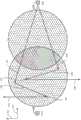
图7A是示出根据本发明的实施例的六投射器波导显示器的的简化平面图。Figure 7A is a simplified plan view illustrating a six-projector waveguide display in accordance with an embodiment of the present invention.
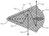
图7B是示出图7A所示的六投射器波导显示器的单个投射器元件的简化平面图。Figure 7B is a simplified plan view showing a single projector element of the six-projector waveguide display shown in Figure 7A.
图7C是示出图7B所示的单个投射器元件的操作的简化k空间图。Figure 7C is a simplified k-space diagram illustrating the operation of the single projector element shown in Figure 7B.
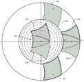
图7D是示出图7A所示的六投射器波导显示器的操作的简化k空间图。Figure 7D is a simplified k-space diagram illustrating the operation of the six-projector waveguide display shown in Figure 7A.
图8是示出根据本发明的实施例的眼镜和一个或多个目镜波导的集成的简化示意图。8 is a simplified schematic diagram illustrating the integration of eyeglasses and one or more eyepiece waveguides according to an embodiment of the present invention.
具体实施方式Detailed ways
本发明大体涉及与包括可穿戴显示器的投影显示系统相关的方法和系统。更特别地,本发明的实施例提供了与传统系统相比具有扩展视场的方法和系统。本发明适用于计算机视觉和图像显示系统以及光场投射系统中的各种应用,这些系统包括立体系统、向用户的视网膜递送光束的系统等。The present invention generally relates to methods and systems related to projection display systems including wearable displays. More particularly, embodiments of the present invention provide methods and systems having an extended field of view compared to conventional systems. The invention finds use in a variety of applications in computer vision and image display systems, as well as light field projection systems, including stereoscopic systems, systems that deliver light beams to a user's retina, and the like.
图1是示出根据本发明的实施例的目镜波导的简化平面图。如图1所示,目镜波导100包括第一耦入光栅(ICG)110和第二ICG 120。组合光瞳扩展器-提取器(CPE)元件130设置在第一ICG 110和第二ICG 120之间。目镜波导100可以实现扩展的视场,该扩展的视场可以大于在波导厚度方向上的引导传播模式中可以支持的传播角度范围。如图2A和2B所示,目镜波导100具有第一表面132和第二表面134。如下文进一步讨论的,可以在目镜波导100的相对表面132和134上或相对表面132和134中形成不同的衍射特征。FIG. 1 is a simplified plan view illustrating an eyepiece waveguide according to an embodiment of the present invention. As shown in FIG. 1 , the
第一ICG 110从第一投射器150(如图2A所示)接收一组输入光束112,并且第二ICG120从第二投射器160(还如图2A所示)接收一组输入光束122。在一些实施例中,输入光束可以通过自由空间从投射器传播,直到它们入射在ICG中的一个上。如图1所示,入射在ICG110上的一组输入光束112和入射在ICG 120上的一组输入光束122相对于z轴成角度或倾斜。ICG 110和ICG 120衍射输入光束,使得输入光束的一部分(其可以是全部)进入目镜波导100内的引导传播模式。ICG 110和ICG 120的栅线可以被取向以将衍射光束沿着x轴朝向CPE 130导引。The
CPE 130可包括沿着多个轴展现出周期的多个衍射特征。因此,CPE130可以由布置在2D网格中的散射特征阵列组成。例如,单独散射特征可以是任何形状的凹痕或凸起。散射特征的2D阵列具有相关联的光栅矢量,该光栅矢量由该2D网格的倒易点格导出。作为一个示例,CPE 130可以是由具有沿着两个或两个以上周期方向重复的栅线的交叉光栅组成的2D衍射光栅。组成CPE 130的衍射特征可以具有相对低的衍射效率(例如,10%或更低)。因此,该低衍射效率允许光束在它们传播通过CPE 130时以空间分布的方式在多个方向上复制。
图2A是示出根据本发明的实施例的具有减小的光栅周期的目镜波导的简化剖视图。图2A所示的设计导致入射在目镜波导的一侧的光优先地在目镜波导的同一侧耦出,从而提供高效率,因为光在穿过目镜波导传播期间不损失,而是在短传播路径之后耦出。而且,由于传播距离和TIR反射次数减少,图像锐度得以保持。如图2A所示,与光栅齿之间测量的光栅节距逆相关的光栅周期被选择为使得以大于零的角度(即,相对于z轴以正角度倾斜)入射在ICG 120上的给定波长的输入光束122的集合的光线沿着以负x轴为中心的方向耦入。对于该具有减小的光栅周期和增加的光栅节距的光栅,如果给定波长的光以法向入射而入射,则光将沿着以相对于负x轴的正角度向上倾斜的方向耦入。因此,减小的光栅周期利用了比传统设计弱的耦入光栅。换句话说,如果波导内角度范围与以法向入射为中心的角度范围的耦入相关联,则光栅周期将减小,使得相对于z轴以正角度倾斜的角度范围将被耦入成相同的波导内角度范围。2A is a simplified cross-sectional view illustrating an eyepiece waveguide with reduced grating period in accordance with an embodiment of the present invention. The design shown in Figure 2A results in light incident on one side of the eyepiece waveguide being preferentially coupled out on the same side of the eyepiece waveguide, thus providing high efficiency because light is not lost during propagation through the eyepiece waveguide, but rather in the short propagation path coupled out afterwards. Also, image sharpness is maintained due to reduced travel distance and TIR reflections. As shown in FIG. 2A , the grating period, which is inversely related to the grating pitch measured between the grating teeth, is chosen such that a given angle incident on the
因此,由相对于z轴以范围从0°到+50°的角度倾斜的光线122定义的角锥体被耦入目镜波导101中,并且在角锥体沿波导向下传播时经历TIR。为了投射以非法线角度入射的光,投射器160可以相对于目镜波导倾斜,可以利用光学器件从垂直于目镜波导取向的投射器引入非法线入射角,等等。Thus, a pyramid defined by
在图2A所示的实施例中,耦出光栅136具有与ICG 120的光栅周期匹配的光栅周期。因此,相对于z轴范围从0°到50°的角锥体123从目镜波导101耦出。换句话说,如果波导内角度的范围在目镜波导101中传播,则耦出光栅136的光栅周期将减小,使得相对于z轴倾斜以正角度的角度范围将从相同的波导内角度范围耦出。尽管在目镜波导101的相对表面上示出了耦入和耦出,但是这不是本发明所要求的,并且耦入和耦出可以从同一表面发生。In the embodiment shown in FIG. 2A , outcoupling grating 136 has a grating period that matches that of
类似地,耦入光栅110的光栅周期被选择为使得以小于零的角度范围(即,相对于z轴以负角度倾斜)入射在ICG 110上的给定波长的输入光束112的光线沿着以正x轴为中心的方向耦入。对于该具有减小的光栅周期和增加的光栅节距的光栅,如果给定波长的光以法向入射而入射,则光沿着以相对于x轴的正角度向上倾斜的方向耦入。因此,由相对于z轴以范围从0°至-50°的角度倾斜的光线112定义的角锥体被耦入目镜波导101中,并且在角锥体沿波导向下传播时经历TIR。为了投射以非法线角度入射的光,投射器150可以相对于目镜波导倾斜,可以利用光学器件从垂直于目镜波导取向的投射器引入非法线入射角,等等。Similarly, the grating period of the in-
在图2A所示的实施例中,耦出光栅138具有与耦入光栅110的光栅周期匹配的光栅周期。因此,相对于z轴范围从0°到-50°的角锥体113从目镜波导101耦出。尽管在目镜波导101的相对表面上示出了耦入和耦出,但是这不是本发明所要求的,并且耦入和耦出可以从同一表面发生。In the embodiment shown in FIG. 2A , the outcoupling grating 138 has a grating period that matches that of the
因此,利用如图2A所示的两个投射器,由投射器150和投射器160产生的两个视场因此相对于目镜波导的法线偏置预定角度,从而产生所示的拼接视场,即组合视场102。因此,本发明的实施例利用了一种波导,其中波导的承载能力(即,基于TIR角度)与非法线入射光和来自传统设计的光栅周期的修改结合被充分利用,以产生拼接视场。Thus, with two projectors as shown in Figure 2A, the two fields of view produced by
因此,使用以减小的光栅周期为特征的设计,在位于目镜波导的一侧的ICG处注入的光优先在目镜波导的同一侧耦出,以形成组合视场的子显示器。如图2A所示,定义相对于z轴以范围从0°到50°的角度倾斜的角锥体的光线122被耦入目镜波导101,并作为角锥体123中的光线耦出,从而形成覆盖相对于z轴从0°到50°的角度范围的第一子显示器。同时,定义相对于z轴范围从0°到-50°的角度倾斜的角锥体的光线112被耦入目镜波导101,并作为角锥体113中的光线耦出,从而形成覆盖相对于z轴从0°到-50°的角度范围的第二子显示器。组合视场102通过拼接第一子显示器和第二子显示器以形成覆盖从-50°到50°的角度范围的等于100°的组合视场102而形成。Thus, using a design featuring a reduced grating period, light injected at the ICG located on one side of the eyepiece waveguide is preferentially coupled out on the same side of the eyepiece waveguide to form a combined field-of-view subdisplay. As shown in FIG. 2A ,
利用聚合物目镜波导材料,包括具有折射率~1.75的聚合物,传统目镜波导设计可以实现~50°的视场。通过利用图2A中所示的具有增加的光栅周期的目镜波导,使用被倾斜以产生入射角的倾斜的对称投射器,并匹配用于耦入和耦出光栅的光栅周期的增加,从而导致输出光的对称倾斜和拼接视场,可以在拼接配置中实现高达100°的组合视场。可替代地,可以以部分重叠的配置实现范围在50°和100°之间的组合视场。Using polymeric eyepiece waveguide materials, including polymers with a refractive index of ~1.75, conventional eyepiece waveguide designs can achieve ~50° fields of view. By utilizing an eyepiece waveguide with increased grating period as shown in Figure 2A, using a tilted symmetric projector that is tilted to produce the angle of incidence, and matching the increase in grating period for coupling in and out of the grating, resulting in the output Symmetrical tilting of light and stitched fields of view, enabling combined fields of view up to 100° in tiled configurations. Alternatively, combined fields of view ranging between 50° and 100° can be achieved in partially overlapping configurations.
尽管图2A示出了以给定角度耦入目镜波导并且以给定角度从目镜波导耦出的光,但是这不是本发明所要求的。在其他实施例中,对耦入光栅和耦出光栅的光栅周期进行修改,以使能以第一角度为中心的第一角锥体的耦入和以不同于第一角度的第二角度为中心的第二角锥体的耦出。本领域普通技术人员将认识到许多变型、修改和替代。Although FIG. 2A shows light coupled into and out of the eyepiece waveguide at a given angle, this is not a requirement of the present invention. In other embodiments, the grating periods of the incoupling and outcoupling gratings are modified to enable incoupling of a first pyramid centered at a first angle and centered at a second angle different from the first angle. Center the outcoupling of the second pyramid. Those of ordinary skill in the art will recognize many variations, modifications, and substitutions.
在图2A所示的实施例中使用的光栅的结构可以在目镜波导的不同区域处变化。在这种具有减小的光栅周期的设计中,闪耀光栅可用于减小耦出效率。作为示例,光栅136可以被闪耀以增加其对从投射器160接收的光的效率,并且光栅138可以被闪耀以增加其对从投射器150接收的光的效率。该闪耀光栅设计将导致较少的来自投射器150的光由光栅136耦出,并且较少的来自投射器160的光由光栅138耦出。在光栅136和光栅138之间的中心区域中,光栅结构可以被分级为以一个闪耀光栅轮廓开始,并以在中心区域中具有二元光栅的另一个闪耀光栅轮廓结束。除了闪耀光栅之外,还可以利用其他衍射表面,特别是以取决于入射光的方向的不同衍射效率为特征的表面,包括超表面和超材料、体积相位全息图、阶梯光栅等。本领域普通技术人员将认识到许多变型、修改和替代。The structure of the grating used in the embodiment shown in Figure 2A can vary at different regions of the eyepiece waveguide. In such a design with reduced grating period, a blazed grating can be used to reduce the outcoupling efficiency. As an example, grating 136 may be flared to increase its efficiency with respect to light received from
图2B是示出根据本发明的实施例的具有增加的光栅周期的目镜波导的简化剖视图。图2B中所示的设计导致入射在目镜波导的一侧的光优先地在目镜波导的相对侧耦出。使用具有增加的光栅周期的设计,可以减小耦入光栅和耦出光栅之间的空间间隔,同时为图像尺寸提供空间扩展,从而减少目镜波导的尺寸。如图2B所示,与光栅齿之间测量122光栅间距成反比的光栅周期被选择为使得以大于零的角度(即,相对于z轴以正角度倾斜)入射在ICG 154上的给定波长的光线122沿着以正x轴为中心的方向耦入。对于该具有增加的光栅周期和减小的光栅节距的光栅,如果给定波长的光以法向入射而入射,则光将沿着以相对于正x轴的正角度向上倾斜的方向耦入。因此,增加的光栅周期利用了比传统设计强的耦入光栅。因此,由相对于z轴以范围从0°至+50°的角度倾斜的光线122定义的角锥体被耦入目镜波导104中,并且在角锥体沿波导向下传播时经历TIR。为了投射以非法线角度入射的光,投射器160可以相对于目镜波导倾斜,可以利用光学器件从垂直于目镜波导取向的投射器引入非法线入射角,等等。2B is a simplified cross-sectional view illustrating an eyepiece waveguide with increased grating period in accordance with an embodiment of the present invention. The design shown in Figure 2B results in light incident on one side of the eyepiece waveguide being preferentially coupled out on the opposite side of the eyepiece waveguide. Using a design with increased grating period, the spatial separation between the in-coupling and out-coupling gratings can be reduced while providing a spatial extension to the image size, thereby reducing the size of the eyepiece waveguide. As shown in FIG. 2B , the grating period, which is inversely proportional to the measured 122 grating pitch between grating teeth, is chosen such that a given wavelength incident on the
在图2B所示的实施例中,耦出光栅156具有与ICG 154的光栅周期匹配的光栅周期。因此,相对于z轴范围从0°到50°的角锥体123从目镜波导104耦出。尽管在目镜波导104的相对表面上示出了耦入和耦出,但是这不是本发明所要求的,并且耦入和耦出可以从同一表面发生。In the embodiment shown in FIG. 2B , outcoupling grating 156 has a grating period that matches that of
类似地,耦入光栅(ICG)164的光栅周期被选择为使得以小于零的角度范围(即,相对于z轴以负角度倾斜)入射在ICG 164上的给定波长的光线112沿着以负x轴为中心的方向耦入。对于该具有增加的光栅周期和减小的光栅节距的光栅,如果给定波长的光以法向入射而入射,则光将沿着以相对于负x轴的正角度向上倾斜的方向耦入。因此,由相对于z轴以范围从0°至-50°的角度倾斜的光线112定义的角锥体被耦入目镜波导104中,并且在角锥体沿波导向下传播时经历TIR。为了投射以非法线角度入射的光,投射器150可以相对于目镜波导倾斜,可以利用光学器件从垂直于目镜波导取向的投射器引入非法线入射角,等等。Similarly, the grating period of the in-coupling grating (ICG) 164 is selected such that
在图2B所示的实施例中,耦出光栅166具有与耦入光栅164的光栅周期匹配的光栅周期。因此,相对于z轴范围从0°到-50°的角锥体113从目镜波导104耦出。尽管在目镜波导104的相对表面上示出了耦入和耦出,但是这不是本发明所要求的,并且耦入和耦出可以从同一表面发生。In the embodiment shown in FIG. 2B , outcoupling grating 166 has a grating period that matches that of
因此,利用如图2B所示的两个投射器,由投射器150和投射器160产生的两个视场因此相对于目镜波导的法线偏置预定角度,从而产生所示的拼接视场,即组合视场105。因此,本发明的实施例利用了一种波导,其中波导的承载能力(即,基于TIR角度)与非法线入射光和来自传统设计的光栅周期的修改结合被充分利用,以产生拼接视场。Thus, with two projectors as shown in Figure 2B, the two fields of view produced by
因此,使用以增加的光栅周期为特征的设计,在位于目镜波导的一侧的ICG处注入的光传播到目镜波导的光被耦出的另一侧,以形成组合视场的子显示器。如图2B所示,定义相对于z轴以范围从0°到50°的角度倾斜的角锥体的光线122被耦入目镜波导104,并作为光线123耦出,从而形成覆盖相对于z轴0°到50°的角度范围的第一子显示器。同时,定义相对于z轴范围从0°到-50°的角度倾斜角锥体的光线112被耦入目镜波导104,并作为光线113耦出,从而形成覆盖相对于z轴0°到-50°的角度范围的第二子显示器。组合视场105通过拼接第一子显示器和第二子显示器以形成覆盖从-50°到50°的角度范围的等于100°的组合视场105而形成。Thus, using a design characterized by an increased grating period, light injected at the ICG located on one side of the eyepiece waveguide propagates to the other side of the eyepiece waveguide where light is coupled out to form a combined field-of-view subdisplay. As shown in FIG. 2B ,
利用聚合物目镜波导材料,包括具有折射率~1.75的聚合物,传统目镜波导设计可以实现~50°的视场。通过利用图2B中所示的具有增加的光栅周期的目镜波导,使用被倾斜以产生入射角的倾斜的对称投射器,并匹配用于耦入和耦出光栅的光栅周期的增加,从而导致输出光的对称倾斜和拼接视场,可以在拼接配置中实现高达100°的组合视场。可替代地,可以以部分重叠的配置实现范围在50°和100°之间的组合视场。Using polymeric eyepiece waveguide materials, including polymers with a refractive index of ~1.75, conventional eyepiece waveguide designs can achieve ~50° fields of view. By utilizing an eyepiece waveguide with increased grating period as shown in Figure 2B, using a tilted symmetric projector that is tilted to produce the angle of incidence, and matching the increase in grating period for coupling in and out of the grating, resulting in the output Symmetrical tilting of light and stitched fields of view, enabling combined fields of view up to 100° in tiled configurations. Alternatively, combined fields of view ranging between 50° and 100° can be achieved in partially overlapping configurations.
尽管图2B示出了以给定角度耦入目镜波导并且以给定角度从目镜波导耦出的光,但是这不是本发明所要求的。在其他实施例中,对耦入光栅和耦出光栅的光栅周期进行修改,以使能以第一角度为中心的第一角锥体的耦入和以不同于第一角度的第二角度为中心的第二角锥体的耦出。本领域普通技术人员将认识到许多变型、修改和替代。Although FIG. 2B shows light coupled into and out of the eyepiece waveguide at a given angle, this is not a requirement of the present invention. In other embodiments, the grating periods of the incoupling and outcoupling gratings are modified to enable incoupling of a first pyramid centered at a first angle and centered at a second angle different from the first angle. Center the outcoupling of the second pyramid. Those of ordinary skill in the art will recognize many variations, modifications, and substitutions.
在图2B所示的实施例中使用的光栅的结构可以在目镜波导的不同区域处变化。在这种具有增加的光栅周期的设计中,闪耀光栅可用于增加耦出效率。作为示例,光栅156可以被闪耀以增加其对从投射器160接收的光的效率,并且光栅166可以被闪耀以增加其对从投射器150接收的光的效率。该闪耀光栅设计将导致较少的来自投射器150的光由光栅156耦出,并且较少的来自投射器160的光由光栅166耦出。在光栅156和光栅166之间的中心区域中,光栅结构可以被分级为以一个闪耀光栅轮廓开始,并以在中心区域中具有二元光栅的另一个闪耀光栅轮廓结束。本领域普通技术人员将认识到许多变型、修改和替代。The structure of the grating used in the embodiment shown in Figure 2B can vary at different regions of the eyepiece waveguide. In this design with increased grating period, a blazed grating can be used to increase the outcoupling efficiency. As an example, grating 156 may be flared to increase its efficiency with respect to light received from
图3A是示出根据本发明的实施例的具有增加的光栅周期和组合视场的目镜波导的元件的简化平面图。在图3A中,示出了光线在波导显示器中的传播和衍射以及产生的视场。如图3A所示,由ICG 305对输入光的衍射导致光衍射到波导的平面中并在波导的平面中传播,如由光线311和315所示。如将描述的,由光线311表示的光线和由光线315表示的光线将导致包括第一部分310a和第二部分310b的视场310(如图3D所示)的生成。3A is a simplified plan view illustrating elements of an eyepiece waveguide with increased grating period and combined field of view, according to an embodiment of the present invention. In FIG. 3A, the propagation and diffraction of light in a waveguide display and the resulting field of view are shown. As shown in FIG. 3A , diffraction of input light by
光线311在从ICG 305衍射之后向右上传播,并且从波导的顶部的光栅衍射,产生光线312,光线312向右下传播。该OPE衍射事件由图3B中的箭头322表示。光线312在波导中传播,并且从波导的下部中的光栅衍射,产生耦出事件313。耦出光线314被示出为从波导的下部向上朝向用户传播,从而产生与用户的视场的下部相关联的视场310的第一部分310a。
同时,光线315在轴301附近向右下传播,并且在轴301附近从波导的下部中的光栅衍射,产生光线316,光线316向右上传播。该OPE衍射事件由图3C中的箭头332表示。光线316在波导中传播,并且在轴301附近从波导的上部中的光栅衍射,产生耦出事件317。耦出光线318被示出为从轴301附近波导的上部向下朝向用户传播,从而产生视场310的下部310b。Simultaneously,
因此,视场310包括与光线311相关联的第一部分310a以及与光线315相关联的第二部分310b。如对于本领域技术人员将明显的,以中间角度耦入并可操作以在波导中传播的光线将填充视场310。Accordingly, field of
图3B是示出用于形成视场的第一部分的第一组光线的图3A所示的目镜波导的操作的简化k空间图。如图3B所示,视场310的第一部分310a行进通过如由位置326和328表示的k空间图,使得其不被由位于n=1.0处的圆和位于n=1.75处的圆定义的对应于波导内角度的环的边界截取。因此,目镜波导的平面内的衍射和目镜波导的平面外的衍射导致在k空间图中行进通过在目镜波导内部传播的区域。FIG. 3B is a simplified k-space diagram illustrating the operation of the eyepiece waveguide shown in FIG. 3A for forming a first set of light rays of a first portion of the field of view. As shown in FIG. 3B, a
参考图3B,来自ICG 305的衍射由箭头320表示,箭头320表示将视场的第一部分310a平移到k空间图的波导内区域的光栅矢量,如位置326所示。如图3A所示,由光线311衍射产生光线312而产生的OPE衍射事件由图3B中的箭头322表示,将视场的第一部分310a从k空间图的波导内区域中的位置326平移到位置328,该位置也在k空间图中的波导内区域中。由光线312衍射产生耦出光线314而产生的EPE耦出事件313由图3B中的箭头324表示,将视场的第一部分310a从k空间图的波导内区域中的位置328平移到与视场的第一部分310a相关联的k空间图的眼空间区域。Referring to FIG. 3B , diffraction from the
因此,如图3B所示的k空间图所指示的,用户的视场的下部中的光由从波导的下部向上朝向用户传播的光线形成,从而产生视场310的第一部分310a。Thus, as indicated by the k-space diagram shown in FIG. 3B , the light in the lower portion of the user's field of view is formed by light rays propagating from the lower portion of the waveguide upwards toward the user, resulting in a
图3B中的k空间图表明,图3A中所示的目镜波导设计具有沿着轴302的由增加的光栅周期表征的光栅间距其,因为视场310a中心作为OPE和EPP衍射事件的结果平移了沿着轴302测量的距离,该距离大于从原点到沿着轴302的在位置328处表示的视场中心所位于的位置的距离。换句话说,参考图3B,沿着轴302测量的距离L大于距离D。相比之下,考虑到沿着轴301的平移的幅度,从原点到点303的距离等于视场310a中心沿着轴301平移的距离,因为沿着轴301的光栅间距不以增加的光栅周期或减小的光栅周期为特征。The k-space diagram in FIG. 3B shows that the eyepiece waveguide design shown in FIG. 3A has a grating pitch characterized by an increased grating period along the
因此,使用包括彼此以~60°取向的栅线的目镜波导设计,光可以在k空间图中沿着三个不同的光栅矢量流动:箭头320表示与轴301对准的光栅矢量,轴301表示ICG到目镜波导的平面中的衍射,并将视场310a平移到位置326;箭头322表示与轴301成~-120°取向的光栅矢量,并且将位置326处的视场平移到位置328;以及箭头324表示与轴301成~60°取向的光栅矢量,并且将位置328处的视场平移到视场310a。由于位置326和328在波导内角度的环内,因此沿着这三个不同光栅矢量衍射的光将保持在目镜波导中。Thus, using an eyepiece waveguide design that includes grating lines oriented at ~60° to each other, light can flow along three different grating vectors in the k-space map:
图3C是示出用于形成视场的第二部分的第二组光线的图3A所示的目镜波导的操作的简化k空间图。参考图3A,光线315在从ICG 305衍射之后在轴301附近向右下传播,最终导致耦出光线318的生成。如图3C所示,来自ICG 305的衍射由箭头330表示,将视场的第二部分310b平移到k空间图的波导内区域,如位置336所示。如图3A所示,由光线315衍射产生光线315而产生的OPE衍射事件由图3C中的箭头332表示,将视场的第二部分310b从k空间图的波导内区域中的位置336平移到位置338,该位置也在k空间图中的波导内区域中。由光线316衍射产生耦出光线318而产生的EPE耦出事件317由图3C中的箭头334表示,将视场的第二部分310b从k空间图的波导内区域中的位置338平移到与视场的第二部分310b相关联的k空间图的眼空间区域。3C is a simplified k-space diagram illustrating the operation of the eyepiece waveguide shown in FIG. 3A for forming a second set of light rays of a second portion of the field of view. Referring to FIG. 3A ,
如关于图3B中所示的第一部分310所讨论的,视场310的第二部分310b行进通过如由位置336和338表示的k空间图,使得其不被由位于n=1.0处的圆和位于n=1.75处的圆定义的对应于波导内角度的环的边界截取。因此,目镜波导的平面内的衍射和目镜波导的平面外的衍射导致在k空间图中行进通过在目镜波导内部传播的区域。As discussed with respect to the
图3D是示出用于视场的图3A所示的目镜波导的操作的简化k空间图。在图3D所示的k空间图中,示出了视场310的第一部分310a和第二部分310b。如关于图3A至3C所讨论的,通过ICG衍射到波导中并且通常向右上以及相对于轴301以小角度向下传播的光线可以在k空间中通过将视场310平移到位置326和336来表示,表示在波导中的传播。由箭头322和332表示的OPE相互作用分别表示从波导的上部到波导的下部的传播和从波导的下部到波导的上部的传播。最后,EPE相互作用由耦出表示,该耦出由眼空间区域中的角度处的视场310表示。Figure 3D is a simplified k-space diagram illustrating the operation of the eyepiece waveguide shown in Figure 3A for a field of view. In the k-space diagram shown in Figure 3D, a
因此,视场310包括与光线311相关联的第一部分310a以及与光线315相关联的第二部分310b。如对于本领域技术人员将明显的,以中间角度耦入并可操作以在波导中传播的光线将填充视场310。Accordingly, field of
图3E是示出用于替代视场的图3A所示的目镜波导的操作的简化k空间图。在图3E中,当光从波导的上部向下朝向用户传播时,形成与用户的视场的下部相关联的视场340。因此,视场340是视场310相对于轴301的镜像。Figure 3E is a simplified k-space diagram illustrating the operation of the eyepiece waveguide shown in Figure 3A for an alternate field of view. In Figure 3E, as light propagates down from the upper portion of the waveguide towards the user, a field of
参考图3E,示出了视场340的第一部分340a和第二部分340b。以类似于关于图3A至3D所示的操作的方式,并且以镜像方式,通过ICG衍射到波导中并且通常向右下以及相对于轴301以小角度向上传播的光线可以在k空间中通过将视场340平移到位置346和356表示,表示在波导中的传播。OPE相互作用分别导致将第一部分平移到位置348和将第二部分平移到位置358,因为这些波导内传播角度由波导支持。最后,EPE相互作用由耦出表示,该耦出由眼空间区域中的角度处的视场340表示。Referring to FIG. 3E , a
因此,作为视场310的镜像,视场340包括与在图3A中向右下传播的光线相关联的第一部分340a以及与在图3A中向右上传播的光线相关联的第二部分340b。如对于本领域技术人员将明显的,以中间角度耦入并可操作以在波导中传播的光线将填充视场340。Thus, as a mirror image of field of
图3F是示出根据本发明的实施例的具有示例性光线的图3A所示的目镜波导的简化平面图。在图3F中,示出了与视场310和340的第一和第二部分相关联的代表性光线。如关于图3A所讨论的,光线311在从ICG 305衍射之后向右上传播,并且从波导的顶部的光栅衍射,产生向右下传播的光线(OPE相互作用)。当该光线与波导的下部中的光栅相互作用时,EPE事件发生,导致光线314的耦出,使得光线314从波导的下部向上朝向用户传播,从而产生视场310的第一部分310a。同时,光线315在轴301附近向右下传播,并且在轴301附近从波导的下部中的光栅衍射,产生向右上传播的光线(OPE相互作用)。当该光线与波导的顶部的光栅相互作用时,EPE事件发生,导致光线318的耦出,使得光线314从波导的顶部向下向用户传播,从而产生视场310的第二部分310b。3F is a simplified plan view showing the eyepiece waveguide shown in FIG. 3A with exemplary light rays in accordance with an embodiment of the present invention. In FIG. 3F, representative rays associated with first and second portions of fields of
以镜像方式,光线381向右下传播,并且从波导的下部中的光栅衍射作为OPE衍射事件,产生光线382,光线382向右上传播。光线382在波导中传播,并且从波导的上部中的光栅衍射,产生耦出事件383。耦出光线384被示出为从波导的上部向下朝向用户传播,从而产生与用户的视场的上部相关联的视场340的第一部分340a。同时,光线385在轴301附近向右上传播,并且在轴301附近从波导的上部中的光栅衍射作为OPE衍射事件,产生光线386,光线386向右下传播。光线386在波导中传播,并且在轴301附近从波导的下部中的光栅衍射,产生耦出事件387。耦出光线388被示出为从轴301附近波导的下部向上朝向用户传播,从而产生视场340的第二部分340b。In a mirrored fashion,
因此,视场340包括与光线381相关联的第一部分340a以及与光线385相关联的第二部分340b。如对于本领域技术人员将明显的,以中间角度耦入并且可操作以在波导中传播的光线将填充视场340。Accordingly, field of
而且,尽管出于清晰的目的,仅示出了四个OPE相互作用和四个EPE相互作用,但是应当理解,光线311/385和315/381将分别在整个波导的顶部和底部经历OPE相互作用。类似地,光线312/386和316/382将分别通过波导的底部和顶部经历EPE相互作用。因此,耦出事件将在整个波导中发生,并且耦出事件313/387和317/383仅是示例性的。因此,跨波导分布的耦出光线将有助于视场310和340的生成。Also, although only four OPE interactions and four EPE interactions are shown for purposes of clarity, it should be understood that
应当注意,在图3F所示的实施例中,波导的顶部和底部中的光栅在轴301处相交,没有重叠。然而,这不是本发明所要求的,并且在一些其他实施例中,光栅在沿着轴302的位置处以轴301上方和/或下方的预定距离重叠。该重叠区域将使传播到波导的顶部中的光线能够经历与源自波导的底部并在重叠区域中延伸到波导的顶部中的光栅的OPE相互作用。继续该示例,传播到波导的顶部中并在重叠区域中经历OPE相互作用的光线将向上衍射到顶部中并可以经历EPE相互作用,该EPE相互作用将导致耦出事件,该耦出事件将增强与视场340相关联的输出。类似地,传播到波导的底部中的光线可以经历与源自波导的顶部并延伸到重叠区域中的波导的底部中的光栅的OPE相互作用。传播到波导的底部中并在重叠区域中经历OPE相互作用的这些光线将向下衍射到底部中并可以经历EPE相互作用,该EPE相互作用将导致耦出事件,该耦出事件将增强与视场310相关联的输出。It should be noted that in the embodiment shown in Figure 3F, the gratings in the top and bottom of the waveguides intersect at
如关于图3G所描述的,利用图3A和3F所示的波导设计,通过视场310和视场340的重叠形成组合视场。因此,尽管每个视场单独提供~50°x~40°的视场(即垂直x水平),但是重叠视场提供~80°x~40°的组合视场,从而显著改善了用户体验。As described with respect to FIG. 3G , with the waveguide design shown in FIGS. 3A and 3F , the combined field of view is formed by the overlap of field of
图3G是示出用于组合视场的图3A所示的目镜波导的操作的简化k空间图。参考图3G,组合视场350由视场310和视场340之间的重叠形成。尽管出于清晰的目的,示出了视场310到位置360和361的平移,但是应当理解,该视场的部分在k空间中平移通过位置366。类似地,出于清晰的目的,示出了视场340到位置365和366的平移,但是应当理解,该视场的部分在k空间中平移通过位置361。如图3G所示,视场310具有垂直~50°×水平-40°的空间范围。类似地,视场340具有类似的空间范围。由于这些视场之间的重叠,形成了以~80°x~40°的更大扩展视场为特征的组合视场。因此,使用本发明的利用单个投射器和以一个维度上增加的光栅周期为特征的光栅的实施例,使能具有增加视场的波导显示器。3G is a simplified k-space diagram illustrating the operation of the eyepiece waveguides shown in FIG. 3A for combining fields of view. Referring to FIG. 3G , combined field of
图4A是示出根据本发明的实施例的利用具有增加的光栅周期的目镜波导的多投射器波导显示器400的简化平面图。以类似于关于图2B所讨论的方式的方式,由ICG 405对输入光的衍射导致光衍射到波导的平面中并在波导的平面中传播,如由光线411和415所示。如将描述的,由光线411表示的光线和由光线415表示的光线将导致包括两个部分的视场的生成,每个部分分别与初始传播到目镜波导的上半部和目镜波导的下半部中的光线相关联。4A is a simplified plan view illustrating a
多投射器波导显示器400包括第一区域403和第二区域404,第一区域403在该实施例中是圆形的,并且第二区域404在该实施例中也是圆形的。第一区域403和第二区域404重叠以形成重叠区域406。在图4A中,重叠区域406设置在ICG 405和ICG 425之间的中点处。第一区域403包括由第一区域403的上半圆定义的第一部分和由第一区域403的下半圆定义的第二部分。同样,第二区域404包括由第二区域404的上半圆定义的第一部分和由第二区域404的下半圆定义的第二部分。重叠区域406由第一区域的第一部分和第二区域的第一部分的重叠以及第一区域的第二部分和第二区域的第二部分的重叠形成。关于图6A提供了与多投射器波导显示器的目镜波导相关的附加描述。The
光线411在从ICG 405衍射之后向右上传播,并且从波导的顶部的光栅衍射,产生光线412,光线412向右下传播。光线412在波导中传播,并且从波导的下部中的光栅衍射,产生耦出事件413。耦出光线414被示出为从波导的下部向上朝向用户传播,从而产生与用户的视场的下部相关联的视场的一部分。
同时,光线415在轴401附近向右下传播,并且在轴401附近从波导的下部中的光栅衍射,产生光线416,光线416向右上传播。光线416在波导中传播,并且在轴401附近从波导的上部中的光栅衍射,产生耦出事件417。耦出光线418被示出为在轴401附近从波导的上部向下朝向用户传播,从而产生视场的下部。如对于本领域技术人员将明显的,以中间角度耦入并可操作以在波导中传播的光线将填充视场。参考图4C,视场410由光线411和415所示出的光线产生。Simultaneously,
图4B是示出来自图4A所示的多投射器波导显示器中的第二投射器的光线的传播的简化平面图。如对于本领域技术人员将明显的,关于图4B所讨论的目镜波导的操作将在一定程度上映照如关于图4A所讨论的目镜波导的操作。即,由ICG 425对源于第二投射器(未示出)的输入光的衍射导致光衍射进入波导的平面中并在波导的平面中传播,如由光线431和435所示。如将描述的,由光线431表示的光线和由光线435表示的光线将导致包括两个部分的视场的生成,每个部分分别与初始传播到目镜波导的上半部和目镜波导的下半部中的光线相关联。Figure 4B is a simplified plan view illustrating the propagation of light from a second projector in the multi-projector waveguide display shown in Figure 4A. As will be apparent to those skilled in the art, the operation of the eyepiece waveguide discussed with respect to FIG. 4B will mirror to some extent the operation of the eyepiece waveguide as discussed with respect to FIG. 4A . That is, diffraction by
光线431在从ICG 425衍射之后向左上传播,并且从波导的顶部的光栅衍射,产生光线432,光线432向左下传播。光线432在波导中传播,并且从波导的下部中的光栅衍射,产生耦出事件433。耦出光线434被示出为从波导的下部向上朝向用户传播,从而产生与用户的视场的下部相关联的视场的一部分。
同时,光线435在轴401附近向左下传播,并且在轴401附近从波导的下部中的光栅衍射,产生光线436,光线436向左上传播。光线436在波导中传播,并且在轴401附近从波导的上部中的光栅衍射,产生耦出事件437。耦出光线438被示出为在轴401附近从波导的上部向下朝向用户传播,从而产生视场的下部。如对于本领域技术人员将明显的,以中间角度耦入并可操作以在波导中传播的光线将填充视场。参考图4C,视场460由光线431和435所示出的光线产生。Simultaneously,
图4C是示出图4A所示的目镜波导的操作的简化k空间图。参考图4C,包括四个视场的组合视场由视场410和视场430与视场460和视场470之间的重叠形成,视场410和视场430由从第一投射器入射的光产生,视场460和视场470由从第二投射器入射的光产生。Figure 4C is a simplified k-space diagram illustrating the operation of the eyepiece waveguide shown in Figure 4A. Referring to FIG. 4C , the combined field of view comprising four fields of view is formed by the overlap between fields of
如图4C所示,单独视场中的每一个具有垂直~50°×水平~40°的空间范围。通过在组合视场中组合四个单独的视场,这些视场之间的重叠产生以~80°x~100°的更大扩展视场为特征的组合视场。因此,使用本发明利用两个投射器和以在两个维度上增加的光栅周期为特征的光栅的实施例,使能具有增加或扩展视场的波导显示器。As shown in Figure 4C, each of the individual fields of view has a spatial extent of ~50° vertically by ~40° horizontally. By combining the four individual fields of view in the combined field of view, the overlap between these fields of view results in a combined field of view characterized by a larger extended field of view of -80° x -100°. Thus, use of an embodiment of the invention utilizing two projectors and a grating featuring an increased grating period in two dimensions enables waveguide displays with increased or extended fields of view.
参考图4C,本发明的实施例提供具有拼接视场的显示器,该拼接视场通过拼接多个单独的视场形成,相邻视场之间有或没有重叠。如对于本领域技术人员将明显的,在具有1.75的折射率的聚合物中制造的目镜波导的该实施例中,由位于n=1.0的圆和位于n=1.75的圆定义的环对应于波导内角度。将理解到,与利用昂贵和特殊材料(例如蓝宝石和铌酸锂)的设计对比,本发明的实施例提供了可以以低成本、低重量和坚固的低折射率材料(诸如聚合物)制造的目镜波导,同时仍提供在组合视场设计中的大视场。尽管本文中的一些讨论与聚合物材料有关,但是本发明的实施例不限于这些材料,并且本文所讨论的概念适用于具有大于1.75的折射率的材料。特别地,具有n=1.75处的边界的环不旨在限制本发明的范围。本领域普通技术人员将认识到许多变型、修改和替代。Referring to FIG. 4C, embodiments of the present invention provide displays having stitched fields of view formed by stitching multiple individual fields of view, with or without overlap between adjacent fields of view. As will be apparent to those skilled in the art, in this embodiment of the eyepiece waveguide fabricated in a polymer having a refractive index of 1.75, the ring defined by the circle at n=1.0 and the circle at n=1.75 corresponds to the waveguide inner angle. It will be appreciated that, in contrast to designs utilizing expensive and exotic materials such as sapphire and lithium niobate, embodiments of the present invention provide low-refractive-index materials that can be fabricated at low cost, low weight, and robustness, such as polymers. Eyepiece waveguides while still providing a large field of view in a combined field of view design. Although some of the discussion herein relates to polymeric materials, embodiments of the invention are not limited to these materials, and the concepts discussed herein are applicable to materials having a refractive index greater than 1.75. In particular, the ring with a boundary at n=1.75 is not intended to limit the scope of the invention. Those of ordinary skill in the art will recognize many variations, modifications, and substitutions.
图4C中的k空间图表明,图4A和4B所示的目镜波导设计以沿着轴401和轴402的增加的光栅周期为特征,因为视场410的中心沿着轴401和轴402平移一定距离,该距离大于从原点到位置419和从原点到位置409的距离。因此,在图4A和4B所示并由图4C中的k空间图所描述的目镜波导设计中,对应于ICG的衍射的k空间中的平移大于从原点到波导内角度的环的中心的距离。即,k空间中的从位置407到位置409的距离(沿着轴401测量的)大于k空间中的从原点到位置409的距离(沿着轴401测量的)(即沿着轴401的增加的光栅周期),并且k空间中的从位置407到位置419的距离(沿着轴402测量的)大于k空间中的从原点到位置419的距离(沿着轴402测量的)(即沿着轴402的增加的光栅周期)。The k-space diagram in Figure 4C shows that the eyepiece waveguide design shown in Figures 4A and 4B is characterized by increased grating period along
如关于图3G更充分地描述并在图4C中所示的,光衍射到目镜波导中和从目镜波导的衍射出以及光在目镜波导中的传播导致视场410、视场430、视场460和视场470在k空间中的若干不同平移。如图4A和图4C所示,从ICG 405衍射的光将使视场410和视场430平移到波导内角度的环的右部。OPE衍射事件将使这些视场分别平移到波导内角度的环的右下和右上部分中。从栅线衍射的作为EPE事件操作的光将使这些视场平移到k空间图的眼空间区域中的视场410和视场430所示的位置。As more fully described with respect to FIG. 3G and shown in FIG. 4C , diffraction of light into and out of the eyepiece waveguides and propagation of light in the eyepiece waveguides results in fields of
如图4B和图4C所示,从ICG 425衍射的光将使视场460和视场470平移到波导内角度的环的左部。OPE衍射事件将使这些视场分别平移到波导内角度的环的左下和左上部分中。从栅线衍射的用作EPE事件的光将使这些视场平移到k空间图的眼空间区域中的视场460和视场470所示的位置。As shown in Figures 4B and 4C, light diffracted from the
如图4C所示,视场中的每一个的中心偏离k空间图的原点。如本文所讨论的,在两个方向上具有增加的周期的光栅的使用导致该垂直和水平偏移。因此,通过使用两个投射器,一个向第一ICG提供图像光,并且一个向第二ICG提供图像光,可以通过对单独视场进行拼接来创建扩展的视场,其中单独视场之间的重叠由光栅特征定义。As shown in Figure 4C, the center of each of the fields of view is offset from the origin of the k-space diagram. As discussed herein, the use of a grating with increasing period in both directions results in this vertical and horizontal offset. Thus, by using two projectors, one providing image light to the first ICG and one providing image light to the second ICG, an extended field of view can be created by stitching the individual fields of view, where the distance between the individual fields of view Overlap is defined by raster features.
应当注意,关于图4A和4B所提供的描述涉及将与投射图像帧的中心像素相关联的中心光线。另外,可以使用上文关于图4A和4B利用的形式来分析图像帧的边缘处形成的光线。这些光线可以称为外围光线。如对于本领域技术人员将明显的,k空间图中的传播与图像空间中的传播逆相关,其中k空间图的上部中的传播对应于图像空间的下部中的传播。如图4A至4C所示,从目镜波导的底部沿着向上方向耦出的光线将以适合于在用户瞳孔相对于目镜波导良好居中时到达用户瞳孔的方式被导引向眼盒。此外,从目镜波导的顶部沿着向下方向耦出的光线将以适合于在用户瞳孔相对于目镜波导良好居中时到达用户瞳孔的方式被导引向眼盒。因此,本发明的实施例提供了有效的设计,其中,当瞳孔在眼盒中良好居中时,光以优选到达用户瞳孔的方式耦出。It should be noted that the description provided with respect to FIGS. 4A and 4B refers to the central ray to be associated with the central pixel of the projected image frame. Additionally, rays formed at the edges of the image frame may be analyzed using the format utilized above with respect to Figures 4A and 4B. These rays may be called peripheral rays. As will be apparent to those skilled in the art, the propagation in the k-space map is inversely related to the propagation in the image space, where the propagation in the upper part of the k-space map corresponds to the propagation in the lower part of the image space. As shown in Figures 4A to 4C, light rays coupled out in an upward direction from the bottom of the eyepiece waveguide will be directed towards the eye box in a manner suitable to reach the user's pupil when the user's pupil is well centered relative to the eyepiece waveguide. Furthermore, light rays coupled out in a downward direction from the top of the eyepiece waveguide will be directed towards the eye box in a manner suitable to reach the user's pupil when the user's pupil is well centered relative to the eyepiece waveguide. Embodiments of the present invention thus provide an efficient design in which light is coupled out in a way that preferentially reaches the user's pupil when the pupil is well centered in the eye box.
通过跟踪与每个图像帧的视场的顶部、视场的底部和视场的侧面相关联的外围光线,发明人已经证明,对应于视场的底部的光线在目镜波导的底部有效地耦出,在目镜波导的顶部具有减少或最小的耦出。因此,通过本发明的实施例增加了到达用户眼睛的眼盒和瞳孔的光效率,因为对于来自向ICG 405提供沿着指向眼盒的向上方向从目镜波导的底部耦出的光的投射器的光,耦出事件被增加和/或最大化,以及对于来自向ICG 425提供沿着指向眼盒的向下方向从目镜波导的顶部耦出的光的投射器的光,耦出事件被增加和/或最大化。By tracing the peripheral rays associated with the top, bottom, and sides of the field of view for each image frame, the inventors have demonstrated that rays corresponding to the bottom of the field of view are efficiently coupled out at the bottom of the eyepiece waveguide , with reduced or minimal outcoupling at the top of the eyepiece waveguide. Thus, the efficiency of light reaching the eye box and pupil of the user's eye is increased by embodiments of the present invention because the light from the projector providing the
图4D是示出根据本发明的实施例的操作由第一区域和第二区域限定的目镜波导的方法的简化流程图。图4D中所示的方法可以在利用图4A和4B所示的目镜波导的多投射器波导显示器的上下文中实现。方法480包括导引来自第一投射器的光以入射在第一耦入光栅(ICG)上(482)。第一投射器,示出为图6A中的投射器621,可以投射入射在示出为图4A中的ICG 405或图6A中的ICG 620的第一ICG上的光。4D is a simplified flowchart illustrating a method of operating an eyepiece waveguide defined by a first region and a second region, according to an embodiment of the present invention. The method shown in Figure 4D can be implemented in the context of a multi-projector waveguide display utilizing the eyepiece waveguide shown in Figures 4A and 4B.
入射在第一ICG上的光被衍射到目镜波导的平面中,并且来自第一投射器的光的一部分被衍射到目镜波导的第一区域的第一部分中、衍射到第二区域的第一部分中、衍射到第二区域的第二部分中、以及衍射到目镜波导之外(484)。参考图4A,衍射到目镜波导的第一区域403的第一部分中的光在没有衍射的情况下传递到第二区域404的第一部分中,而在图6A中,衍射到目镜波导的第一区域601的第一部分602中的光在目镜波导的平面中朝向第二区域604的第一部分605衍射。因此,在一些实施例中,目镜波导的第一区域的第一部分包括第一组衍射光学元件,例如,被闪耀并以来自第一投射器的光的减小的耦出效率为特征的第一组光栅。Light incident on the first ICG is diffracted into the plane of the eyepiece waveguide, and a portion of the light from the first projector is diffracted into a first portion of a first region of the eyepiece waveguide, into a first portion of a second region , into a second portion of the second region, and out of the eyepiece waveguide (484). Referring to FIG. 4A, light diffracted into the first portion of the
当光在目镜波导的第二区域的第一部分中传播时,来自衍射光学元件(例如光栅)的衍射导致光朝向第二区域404的第二部分重导引,如图4A中的光线412所示。第二区域的第一部分中的光栅可以相对于穿过ICG 405和ICG 425之间的轴以~150°取向。此外,图4A所示的光线412在波导中传播,并且从第二区域的第二部分中的光栅衍射,从而产生从目镜波导的耦出。第二区域的第二部分中的光栅可以相对于穿过ICG 405和ICG425之间的轴以~-150°取向。如关于图4A所描述的,耦出光线从波导的第二区域的第二部分向上朝向用户传播,从而产生与用户的视场的下部相关联的视场的一部分。As light propagates in the first portion of the second region of the eyepiece waveguide, diffraction from the diffractive optical element (e.g., a grating) causes the light to be redirected toward the second portion of the
来自第一投射器的光的另一部分被衍射到目镜波导的第一区域的第二部分中、衍射到第二区域的第二部分中、衍射到第二区域的第一部分中、以及衍射到目镜波导之外(486)。参考图4A,衍射到目镜波导的第一区域403的第二部分中的光在没有衍射的情况下传递到第二区域404的第二部分中,而在其他实施例中,衍射到目镜波导的第一区域的第二部分中的光在目镜波导的平面中朝向第二区域的第二部分衍射。因此,在一些实施例中,目镜波导的第一区域的第二部分包括第二组衍射光学元件,例如,被闪耀并以来自第一投射器的光的减小的耦出效率为特征的第二组光栅。Another portion of the light from the first projector is diffracted into a second portion of the first region of the eyepiece waveguide, into a second portion of the second region, into a first portion of the second region, and into the eyepiece Beyond the waveguide (486). Referring to FIG. 4A , light diffracted into the second portion of the
当光在目镜波导的第二区域的第二部分中传播时,来自衍射光学元件(例如光栅)的衍射导致光朝向第二区域404的第一部分重导引,如图4A中的光线416所示。第一区域的第一部分中的光栅可以相对于穿过ICG 405和ICG 425之间的轴以~30°取向。此外,图4A所示的光线416在波导中传播,并且从第二区域404的第一部分中的光栅衍射,从而从目镜波导的耦出。第一区域的第二部分中的光栅可以相对于穿过ICG 405和ICG 425之间的轴以~-30°取向。如关于图4A所描述的,耦出光线从波导的第二区域的第一部分向下朝向用户传播,从而产生与用户的视场的上部相关联的视场的一部分。As light propagates in the second portion of the second region of the eyepiece waveguide, diffraction from the diffractive optical element (e.g., a grating) causes the light to be redirected toward the first portion of the
方法还包括导引来自第二投射器的光以入射在第二耦入光栅(ICG)上(488)。第二投射器,示出为图6A中的第二投射器626,可以投射入射在示出为图4A中的ICG 425或图6A中的ICG 625的第二ICG上的光。The method also includes directing light from the second projector to be incident on a second incoupling grating (ICG) (488). A second projector, shown as
入射在第二ICG上的光被衍射到目镜波导的平面中,并且来自第二投射器的光的一部分被衍射到目镜波导的第二区域的第一部分中、衍射到第一区域的第一部分中、衍射到第一区域的第二部分中、以及衍射到目镜波导之外(490)。参考图4B,衍射到目镜波导的第二区域404的第一部分中的光在没有衍射的情况下传递到第一区域403的第一部分中,而在其他实施例中,衍射到目镜波导的第二区域的第一部分中的光在目镜波导的平面中朝向第一区域的第一部分衍射。因此,在一些实施例中,目镜波导的第二区域的第一部分包括第三组衍射光学元件,例如,被闪耀并以来自第二投射器的光的减小的耦出效率为特征的第三组光栅。Light incident on the second ICG is diffracted into the plane of the eyepiece waveguide, and a portion of the light from the second projector is diffracted into a first portion of a second region of the eyepiece waveguide, into a first portion of the first region , into a second portion of the first region, and out of the eyepiece waveguide (490). Referring to FIG. 4B, light diffracted into the first portion of the
当光在目镜波导的第一区域的第一部分中传播时,来自衍射光学元件(例如光栅)的衍射导致光朝向第一区域的第二部分重导引,如图4B中的光线432所示。第一区域的第一部分中的光栅可以相对于穿过ICG 405和ICG 425之间的轴以~30°取向。此外,图4B所示的光线432在波导中传播,并且从第一区域的第二部分中的光栅衍射,从而产生从目镜波导的耦出。第一区域的第二部分中的光栅可以相对于穿过ICG 405和ICG 425之间的轴以~-30°取向。如关于图4B所描述的,耦出光线从波导的第一区域的第二部分向上朝向用户传播,从而产生与用户的视场的下部相关联的视场的一部分。As light propagates in a first portion of the first region of the eyepiece waveguide, diffraction from a diffractive optical element (eg, a grating) causes the light to be redirected toward a second portion of the first region, as shown by
来自第二投射器的光的另一部分被衍射到目镜波导的第二区域的第二部分中、衍射到第一区域的第二部分中、衍射到第一区域的第一部分中、以及衍射到目镜波导之外(492)。参考图4B,衍射到目镜波导的第二区域的第二部分中的光在没有衍射的情况下传递到第一区域的第二部分中,而在其他实施例中,衍射到目镜波导的第二区域的第二部分中的光在目镜波导的平面中朝向第一区域的第二部分衍射。因此,在一些实施例中,目镜波导的第二区域的第二部分包括第四组衍射光学元件,例如,被闪耀并以来自第二投射器的光的减小的耦出效率为特征的第四组光栅。Another portion of the light from the second projector is diffracted into a second portion of the second region of the eyepiece waveguide, into a second portion of the first region, into a first portion of the first region, and into the eyepiece Beyond the waveguide (492). Referring to FIG. 4B , light diffracted into the second portion of the second region of the eyepiece waveguide passes without diffraction into the second portion of the first region, while in other embodiments, light diffracted into the second portion of the eyepiece waveguide Light in the second part of the region is diffracted in the plane of the eyepiece waveguide towards the second part of the first region. Thus, in some embodiments, the second portion of the second region of the eyepiece waveguide includes a fourth set of diffractive optical elements, e.g., a fourth set of diffractive optical elements that are flared and characterized by reduced outcoupling efficiency of light from the second projector. Four groups of gratings.
当光在目镜波导的第一区域的第二部分中传播时,来自衍射光学元件(例如光栅)的衍射导致光朝向第一区域的第一部分重导引,如图4B中的光线436所示。第一区域的第二部分中的光栅可以相对于穿过ICG 405和ICG 425之间的轴以~-30°取向。此外,图4B所示的光线436在波导中传播,并且从第一区域的第一部分中的光栅衍射,从而产生从目镜波导的耦出。第一区域的第一部分中的光栅可以相对于穿过ICG 405和ICG425之间的轴以~30°取向。如关于图4B所描述的,耦出光线从波导的第一区域的第一部分向下朝向用户传播,从而产生与用户的视场的上部相关联的视场的一部分。As light propagates in the second portion of the first region of the eyepiece waveguide, diffraction from the diffractive optical element (eg, grating) causes the light to be redirected toward the first portion of the first region, as shown by
在一些实施例中,来自第一投射器的光以第一非零入射角入射在第一ICG上,以及来自第二投射器的光以等于零减去第一非零入射角的第二非零入射角入射在第二ICG上。在这些实施例中,第二区域的第一部分的第一视场以非零入射角为中心,且第一区域的第一部分的第二视场以非零入射角为中心。In some embodiments, light from the first projector is incident on the first ICG at a first non-zero angle of incidence, and light from the second projector is incident on the first ICG at a second non-zero angle of incidence equal to zero minus the first non-zero angle of incidence. The incident angle is incident on the second ICG. In these embodiments, the first field of view of the first portion of the second region is centered at a non-zero angle of incidence, and the second field of view of the first portion of the first region is centered at a non-zero angle of incidence.
应当理解,根据本发明的实施例,图4D所示的具体步骤提供了操作由第一区域和第二区域定义的目镜波导的特定方法。还可以根据可替代实施例执行其他步骤序列。例如,本发明的可替代实施例可以以不同的顺序执行上述步骤。而且,图4D所示的单独步骤可包括多个子步骤,这些子步骤可以以适合于单独步骤的各种顺序执行。此外,可以取决于特定应用添加或移除附加步骤。本领域普通技术人员将认识到许多变型、修改和替代。It should be understood that the specific steps shown in FIG. 4D provide a specific method of operating the eyepiece waveguide defined by the first region and the second region, according to an embodiment of the present invention. Other sequences of steps may also be performed according to alternative embodiments. For example, alternative embodiments of the present invention may perform the steps described above in a different order. Furthermore, the individual steps shown in FIG. 4D may include multiple sub-steps, which may be performed in various orders as appropriate for the individual steps. Furthermore, additional steps may be added or removed depending on the particular application. Those of ordinary skill in the art will recognize many variations, modifications, and substitutions.
图5A是示出根据本发明的实施例的利用具有减小的光栅周期的目镜波导的多投射器波导显示器的简化平面图。关于图4A至4C所提供的描述适用于图5A至5C,但是用于具有减小的光栅周期的目镜波导。5A is a simplified plan view illustrating a multi-projector waveguide display utilizing an eyepiece waveguide with reduced grating period in accordance with an embodiment of the present invention. The description provided with respect to Figures 4A to 4C applies to Figures 5A to 5C, but for an eyepiece waveguide with reduced grating period.
在光栅周期通过增加光栅节距来减小的该设计中,光在沿着目镜波导传播减少的距离之后耦出。参考图5A,入射在ICG 505上的光在邻近ICG505的目镜波导的视场510中耦出。类似地,入射在ICG 525上的光在邻近ICG 525的目镜波导的视场530中耦出。In this design where the grating period is reduced by increasing the grating pitch, light is outcoupled after traveling a reduced distance along the eyepiece waveguide. Referring to FIG. 5A , light incident on the
图5B是示出图5A所示的目镜波导的操作的简化k空间图。Figure 5B is a simplified k-space diagram illustrating the operation of the eyepiece waveguide shown in Figure 5A.
图5B中的k空间图表明,图5A中所示的目镜波导设计是以沿着轴501的减小的光栅周期和沿着轴502的增加的光栅周期为特征的设计。沿着轴501的减小的光栅周期通过视场510/560的中心沿着轴501平移一定距离示出,该距离小于从原点到波导内角度的环的中心的距离。类似地,视场530/570的中心沿着轴501平移一定距离,该距离小于从原点到波导内角度的环的中心的距离。在与轴502对准的垂直方向上,证明了与上文关于图4C所讨论的行为类似的行为。因此,视场510/560的中心沿着轴502平移一定距离,该距离大于从原点到波导内角度的环的中心的距离。类似地,视场530/570的中心沿着轴501平移一定距离,该距离大于从原点到波导内角度的环的中心的距离。The k-space diagram in FIG. 5B shows that the eyepiece waveguide design shown in FIG. 5A is a design characterized by a reduced grating period along
如图5B所示,使用图5A所示的目镜波导设计实现的视场可以达到沿着第一方向~50°至约~180°在与第一方向正交的第二方向上最远范围达到~50°的视场。应当注意,k空间图的上部中的视场510和560和k空间图的下部中的视场530和570的组合导致区域575中的凹口,该凹口可以对于特定应用而酌情遮蔽。As shown in FIG. 5B , the field of view achieved using the eyepiece waveguide design shown in FIG. 5A can range from ~50° to about ~180° along a first direction with a furthest range in a second direction orthogonal to the first direction. ~50° field of view. It should be noted that the combination of fields of
图6A是示出根据本发明的实施例的多投射器波导显示器的元件的简化平面图。如图6A所示并且如在下面更充分地描述的,目镜波导600(其也可以被称为波导显示器组件)包括ICG 620,其可以被称为第一ICG。ICG 620可操作以接收来自第一投射器621的输入光。如关于图1所讨论的,ICG 620接收沿着具有与z轴对准的分量(即,垂直于位于x-y平面中的目镜波导600的输入表面)的方向传播的输入光,并将输入光的至少一部分耦合到波导中。Figure 6A is a simplified plan view showing elements of a multi-projector waveguide display according to an embodiment of the present invention. As shown in FIG. 6A and as described more fully below, eyepiece waveguide 600 (which may also be referred to as a waveguide display assembly) includes an
目镜波导600还包括ICG 625,该ICG 625可以被称为第二ICG。ICG625可操作为接收来自第二投射器626的输入光。如关于图1所讨论的,ICG 620接收沿着具有与z轴对准的分量(即,垂直于位于x-y平面中的目镜波导600的输入表面)的方向传播的输入光,并将输入光的至少一部分耦合到波导中。The
ICG 620和ICG 625沿着位于目镜波导的平面内的x轴设置。参考图6A,波导显示器600还包括多个区域,在这些多个区域中,光在波导显示器的平面内衍射并衍射出波导显示器的平面。这些多个区域包括第一区域601和第二区域604。在每个区域中,区域的一部分中存在的栅线或其他衍射结构以相对于区域的其他部分中存在的其他栅线或相对于其他区域(或多个区域中的其他区域)中的栅线以预定角度取向。
应当注意,在图6A和图6B所示的两种投射器设计中,区域的一部分中的光栅可以取决于入射在光栅上的光的源来执行不同的衍射功能。作为示例,当在第二区域604的第二部分606中传播时,入射在ICG 620上的光可以与第二部分606中的光栅相互作用以从目镜波导耦出。也就是说,第二部分606中的光栅可以用作来自投射器621的光的EPE光栅。相反,当在第二区域604的第二部分606中传播时,入射在ICG 625上的光可以与第二部分606中的光栅相互作用,以在目镜波导的平面中朝向第一部分605衍射。也就是说,第二部分606中的光栅可以用作来自第二投射器626的光的OPE光栅。对于其他部分中的其他光栅,类似的不同效果将是明显的,导致取决于在目镜波导中传播的光的源的不同功能(即OPE或EPE功能)。本领域普通技术人员将认识到许多变型、修改和替代。It should be noted that in both projector designs shown in Figures 6A and 6B, the grating in a portion of the area may perform different diffractive functions depending on the source of light incident on the grating. As an example, when propagating in the
与仅具有单组光栅的第二部分606的区域相比,第一区域601和第二区域604之间的重叠区域630将产生多重效果,例如EPE和OPE效果。由于存在多组光栅,因此将针对从两个投射器入射的光产生衍射效应。The overlapping
用于在第一区域601的第一部分602和第二部分603以及第二区域604的第一部分605和第二部606中提供光栅的实际实现可以变化。作为示例,第一区域601的第二部分603和第二区域604的第一部分605中的光栅(即,与x轴成-30°取向的光栅)可以形成在用于制造目镜波导的基板的第一表面上,以及第一区域601的第一部分602和第二区域604的第二部分606中的光栅(即,与x轴成30°取向的光栅)可以形成在基板的与第一表面相对的第二表面上。因此,重叠区域630可以由存在于目镜波导的两个表面上的光栅形成。The actual implementation for providing gratings in the
图6B是示出根据本发明的实施例的多投射器波导显示器中的光线的传播的简化平面图。Figure 6B is a simplified plan view illustrating the propagation of light rays in a multi-projector waveguide display according to an embodiment of the present invention.
参考图6A和6B,第一区域601包括第一部分602,也称为上部或顶部,其以与ICG620和ICG 625所沿着定位的x轴成~30°的角度取向的栅线616为特征。第一区域601还包括第二部分603,也称为下部或底部,其以与x轴成~-30°的角度取向的栅线618为特征。因此,栅线616和栅线618彼此以~60°的角度取向。如对于本领域技术人员将明显的,出于清晰的目的,栅线616和618之间的间距未按比例绘制。Referring to FIGS. 6A and 6B , the
第二区域604包括第一部分605,也称为上部或顶部,其以与x轴成~120°的角度取向的栅线629为特征。第二区域604还包括第二部分606,也称为下部或底部,其以与x轴成~-120°的角度取向的栅线628为特征。因此并且以类似于第一区域601的方式,第二区域604中的栅线629和栅线628彼此以~60°的角度取向。如对于本领域技术人员将明显的,出于清晰的目的,栅线629和628之间的间距未按比例绘制。The
在重叠区域630中,栅线616与栅线629重叠,并且栅线618与栅线638重叠。因此,除了包括单组栅线的部分之外,重叠区域630还包括多组重叠栅线,并且可以称为交叉区域。该重叠区域使得设计者能够实现具有更大出射光瞳的设计,并且随着出射光瞳尺寸的增加平衡目镜波导的操作的效率,这对用户的眼瞳的运动更宽容。In overlapping
尽管第一区域601的第一部分602中的栅线616和第一区域601的第二部分603中的栅线618被示出为在x轴处相交,其中第二部分603中的栅线616与第一部分602中的栅线618没有重叠,但是这不是本发明的实施例所要求的。在一些实施例中,栅线616延伸到第二部分603中,并且栅线618延伸到第一部分602中。Although the
如本文更充分地描述的,第一区域601和第二区域604的不同部分中的栅线的存在,包括重叠区域630中的栅线的重叠,使得栅线能够用作正交光瞳扩展器(OPE),从而将在目镜波导的平面中传播的光衍射到新传播方向中,并且扩展在目镜波导中传播的光的横向尺寸;以及用作出射光瞳扩展器(EPE),从而将在目镜波导的平面中传播的光衍射到目镜波导的平面之外。特别值得注意的是,取决于光在目镜波导中传播的方向,一组栅线可以用作OPE或EPE。作为示例,对于给定的一组栅线,在第一方向上传播的光可以在目镜波导的平面中衍射(OPE功能),而在与第一方向正交的第二方向上传播的光可以衍射到目镜波导的平面之外(EPE功能)。As described more fully herein, the presence of the gridlines in different portions of the
参考图6A和6B,当光传播通过第一区域601的第一部分602时,与栅线616的相互作用导致沿着ICG之间的轴的方向的在目镜波导的平面中的衍射。作为该衍射的结果,类似于OPE衍射,图像的第一副本的多个副本被形成并在与该轴对准的方向上传播。Referring to Figures 6A and 6B, when light propagates through the
从第一部分602传播到重叠区域630的光,由于与x轴成~30°取向的栅线以及与x轴成~120°取向的栅线的存在,在目镜波导的平面内以及目镜波导的平面外经历多个方向上的衍射。在与x轴对准的方向上传播的光将遇到栅线629,并且将在目镜波导的平面中沿着由箭头627所示的方向衍射。当光沿着该方向传播时,光将遇到栅线628,并将经历从目镜波导的耦出事件。这些耦出事件在图6B中由开口圆示出。Light propagating from the
参考第一部分605,在与x轴对准的方向上传播的光穿过重叠区域630,遇到栅线629,并且在目镜波导的平面中沿着箭头627的方向衍射。在这些衍射事件期间,光的梯式递进将对于OPE功能酌情发生。当光沿着箭头627的方向进一步传播时,光将进入第二部分606,遇到栅线628,并经历从目镜波导的附加耦出事件。这些耦出事件,像在重叠区域630中产生的耦出事件那样,在图6B中由开口圆示出。Referring to
因此,在ICG 620处进入目镜波导且由第一投射器621生成的光可以在第二区域604中耦出。在图6A和6B所示的设计中,在ICG 620处耦合到目镜波导中的光优选地穿过第一区域601而不经历耦出事件,从而通过耦出导致几乎没有光损失,其中通过第一区域601仅导致目镜波导的平面中的衍射,复制了OPE功能。因此,来自第一投射器的光的所有耦出事件优选地在第二区域604中经历,该第二区域提供形成组合显示器的子显示器中的一个的输出。因为,如图2B所示,进入ICG的光线锥以非法线入射角为中心,在第二区域604中耦出的光线锥也以非法线入射角传播,使能子显示器之间的空间分离和组合显示器的拼接。Thus, light entering the eyepiece waveguide at
除了进入ICG 620的光之外,进入ICG 605的光在它传播通过第二区域604时将经历类似的相互作用,导致OPE相互作用,并且在第一区域601中经历EPE相互作用。本领域普通技术人员将认识到许多变型、修改和替代。In addition to light entering
图7A是示出根据本发明的实施例的六投射器波导显示器的简化平面图。在图7A所示的六投射器设计中,六个投射器围绕目镜波导的周边以60°角设置。图7A所示的六投射器波导显示器是利用减小的光栅周期的设计。Figure 7A is a simplified plan view illustrating a six-projector waveguide display in accordance with an embodiment of the present invention. In the six-projector design shown in Figure 7A, six projectors are arranged at a 60° angle around the perimeter of the eyepiece waveguide. The six-projector waveguide display shown in Figure 7A is a design utilizing a reduced grating period.
来自六个投射器(未示出)的光经由ICG 710、713、714、716、718和720耦合到共享目镜波导区域中。共享目镜波导区域包括三个不同的光栅矢量,包括:光栅矢量722,其与穿过连接ICG 713和714的线的垂直平分线和连接ICG 718和720的线的垂线平分线的轴(即垂直取向轴702)对准;光栅矢量724,其与穿过连接ICG 710和720的线的垂直平分线和连接ICG 714和716的线的垂线平分线的轴(即与垂直轴702成-30°取向的轴)对准;以及光栅矢量726,其与穿过连接ICG 716和718的线的垂直平分线和连接ICG 710和713的线的垂线平分线的轴(即与垂直轴702成+30°取向的轴)对准。Light from six projectors (not shown) is coupled via
参考ICG 710,经由ICG 710耦入的光在区域712和719中沿着具有与轴701对准的分量的方向传播。区域712和719利用类似于图5A所示的设计的设计,即人字形设计,其中区域712中的光栅以与水平轴701成-120°的角度倾斜,并且区域719中的光栅以与水平轴701成120°的角度倾斜。与视场的底部相关联的光传播通过区域719,经历朝向区域712的衍射(例如,几乎没有耦出),并且从区域712耦出。类似地,与视场的顶部相关联的光传播通过区域712,经历朝向区域719的衍射(例如,几乎没有耦出),并且从区域719耦出。关于图7B提供了与这些相互作用相关的附加描述。Referring to
利用图7A所示的六投射器设计,包括六个耦入光栅和共享目镜波导区域,在具有~1.75的折射率的聚合物目镜中实现~100°的组合锥形视场。Using the six-projector design shown in Figure 7A, including six in-coupling gratings and a shared eyepiece waveguide region, a combined conical field of view of ~100° is achieved in a polymer eyepiece with a refractive index of ~1.75.
图7B是示出图7A所示的六投射器波导显示器的单个投射器元件的简化平面图。图7C是示出图7B所示的单个投射器元件的操作的简化k空间图。参考图7B和7C,可以描述光衍射和k空间中的伴随的视场平移。如图7B所示,当光传播到区域712中时,从ICG 710衍射的光的一部分可以由光线740表示。来自区域712中的光栅的衍射将导致导向波导的上半部(即区域719)的光线741的生成。这可以被认为是OPE事件。Figure 7B is a simplified plan view showing a single projector element of the six-projector waveguide display shown in Figure 7A. Figure 7C is a simplified k-space diagram illustrating the operation of the single projector element shown in Figure 7B. Referring to Figures 7B and 7C, light diffraction and the accompanying translation of the field of view in k-space can be described. As shown in FIG. 7B , a portion of the light diffracted from
在传播到波导的上半部(即区域719)中之后,来自区域719中的光栅的衍射将导致生成向下朝向用户传播的输出光线742,表示用户的视场的上部中的光。After propagating into the upper half of the waveguide (ie, region 719), diffraction from the grating in
类似地,当光线750在从ICG 710衍射之后传播到波导的上半部(即区域719)中时,将产生用户的视场的下部中的光。从光栅到波导的上半部(即区域719)的衍射将导致光线751的生成(OPE事件),光线751传播到波导的下半部,即区域712。区域712中作为EPE事件的衍射将导致向上朝向用户传播的输出光线752的生成。Similarly, when
应当注意,尽管图7A和7B所示的共享目镜波导区域仅包括在栅线重叠的中心区域中的相邻光栅矢量之间的重叠。在其他实施例中,重叠区域可以延伸得更靠近相应ICG中的每一个。这些具有增加的重叠的设计使能了这样的性能,其中,如果用户的瞳孔在眼盒中移动到偏离眼盒的中心的位置,则视场的可见度对可能由用户注视的变化引起的用户瞳孔偏离中心良好的瞳孔位置的这种偏差更宽容。It should be noted that although the shared eyepiece waveguide region shown in Figures 7A and 7B only includes overlap between adjacent grating vectors in the central region where the grating lines overlap. In other embodiments, the overlapping regions may extend closer to each of the respective ICGs. These designs with increased overlap enable a performance in which, if the user's pupil moves in the eye box to a position off-center of the eye box, the visibility of the field of view has no effect on the user's pupil deviation, which may be caused by changes in the user's gaze. Well-centered pupil positions are more forgiving of this deviation.
参考图7C,来自ICG 710的衍射对应于视场730到位置732的平移。由光线751表示的来自区域719中的光栅的衍射(OPE事件)导致视场平移到位置734,并且区域712中的衍射(EPE事件)导致视场平移到k空间图的眼空间区域。Referring to FIG. 7C , diffraction from
类似地,由光线741表示的来自区域712中的光栅的衍射(OPE事件)导致视场平移到位置736,并且区域719中的衍射(EPE事件)导致视场平移到k空间图的眼空间区域。Similarly, diffraction from the grating in
图7C中的k空间图表明,图7B所示的目镜波导设计利用了具有沿着轴701的减小的光栅周期的光栅,因为视场730的中心沿着轴701平移一定距离,该距离小于从原点到波导内角度的环的距离。The k-space diagram in FIG. 7C shows that the eyepiece waveguide design shown in FIG. 7B utilizes a grating with reduced grating period along
图7D是示出图7A所示的六投射器波导显示器的操作的简化k空间图。当对图7B所示的六投射器波导显示器的一部分执行的分析扩展到五个其他投射器时,如图7D所示,产生包括六个部分重叠视场的组合视场。该组合视场是通过拼接单独视场形成的,这些单独视场通常是具有圆形终端的锥形扇区,从而导致圆形的组合视场,并且其以具有~1.75的折射率的聚合物目镜中的~100°的组合锥形视场为特征。Figure 7D is a simplified k-space diagram illustrating the operation of the six-projector waveguide display shown in Figure 7A. When the analysis performed on a portion of the six-projector waveguide display shown in Figure 7B is extended to five additional projectors, as shown in Figure 7D, a combined field of view comprising six partially overlapping fields of view results. The combined field of view is formed by splicing the individual fields, which are usually cone-shaped sectors with circular terminations, resulting in a circular combined field of view, and it is formed in a polymer with a refractive index of ~1.75 A combined cone of field of ~100° in the eyepiece is characterized.
图8是示出根据本发明的实施例的眼镜和一个或多个目镜波导的集成的简化透视图。如图8所示,目镜波导可以集成到一副眼镜的右镜框801和左镜框802中。由于本文所描述的目镜波导的功能,右镜框801中的第一目镜波导830和左镜框802中的第二目镜波导840的集成使能了宽视场。如图8所示,第一波导显示器805利用两个目镜波导830和840,每个目镜波导包括ICG 832/842和CPE 834/844。8 is a simplified perspective view illustrating the integration of eyeglasses and one or more eyepiece waveguides according to an embodiment of the present invention. As shown in Figure 8, the eyepiece waveguides can be integrated into the
还应理解,本文所描述的示例和实施例仅用于说明目的,并且根据其进行的各种修改或改变暗示给本领域技术人员,并且将包括在本申请的精神和范围内以及权利要求书的范围内。It should also be understood that the examples and embodiments described herein are for illustrative purposes only, and that various modifications or changes based thereon are suggested to those skilled in the art and are to be included within the spirit and scope of the application and the claims In the range.
Claims (32)
Translated fromChineseApplications Claiming Priority (3)
| Application Number | Priority Date | Filing Date | Title |
|---|---|---|---|
| US202063029312P | 2020-05-22 | 2020-05-22 | |
| US63/029,312 | 2020-05-22 | ||
| PCT/US2021/033768WO2021237168A1 (en) | 2020-05-22 | 2021-05-21 | Method and system for dual projector waveguide displays with wide field of view |
Publications (1)
| Publication Number | Publication Date |
|---|---|
| CN115668033Atrue CN115668033A (en) | 2023-01-31 |
Family
ID=78608879
Family Applications (1)
| Application Number | Title | Priority Date | Filing Date |
|---|---|---|---|
| CN202180036347.XAPendingCN115668033A (en) | 2020-05-22 | 2021-05-21 | Method and system for dual-projector waveguide display with wide field of view |
Country Status (5)
| Country | Link |
|---|---|
| US (4) | US11536972B2 (en) |
| EP (1) | EP4154051A4 (en) |
| JP (1) | JP7731374B2 (en) |
| CN (1) | CN115668033A (en) |
| WO (1) | WO2021237168A1 (en) |
Families Citing this family (20)
| Publication number | Priority date | Publication date | Assignee | Title |
|---|---|---|---|---|
| US9933684B2 (en) | 2012-11-16 | 2018-04-03 | Rockwell Collins, Inc. | Transparent waveguide display providing upper and lower fields of view having a specific light output aperture configuration |
| US9632226B2 (en) | 2015-02-12 | 2017-04-25 | Digilens Inc. | Waveguide grating device |
| CN113759555B (en) | 2015-10-05 | 2024-09-20 | 迪吉伦斯公司 | Waveguide Display |
| EP3542213B1 (en) | 2016-11-18 | 2025-10-08 | Magic Leap, Inc. | Waveguide light multiplexer using crossed gratings |
| EP3710894B1 (en) | 2018-01-08 | 2025-07-30 | Digilens Inc. | Methods for fabricating optical waveguides |
| US10732569B2 (en) | 2018-01-08 | 2020-08-04 | Digilens Inc. | Systems and methods for high-throughput recording of holographic gratings in waveguide cells |
| US20200225471A1 (en) | 2019-01-14 | 2020-07-16 | Digilens Inc. | Holographic Waveguide Display with Light Control Layer |
| US20220283377A1 (en)* | 2019-02-15 | 2022-09-08 | Digilens Inc. | Wide Angle Waveguide Display |
| EP3980825A4 (en) | 2019-06-07 | 2023-05-03 | Digilens Inc. | WAVEGUIDES WITH TRANSMITTING AND REFLECTING GRIDS AND RELATED MANUFACTURING PROCESSES |
| US11650423B2 (en)* | 2019-06-20 | 2023-05-16 | Magic Leap, Inc. | Eyepieces for augmented reality display system |
| KR102775783B1 (en) | 2019-08-29 | 2025-02-28 | 디지렌즈 인코포레이티드. | Vacuum grid and method for manufacturing the same |
| CN115668033A (en)* | 2020-05-22 | 2023-01-31 | 奇跃公司 | Method and system for dual-projector waveguide display with wide field of view |
| EP4020058A1 (en)* | 2020-12-23 | 2022-06-29 | TriLite Technologies GmbH | Augmented reality display |
| WO2022150841A1 (en) | 2021-01-07 | 2022-07-14 | Digilens Inc. | Grating structures for color waveguides |
| JP7465826B2 (en)* | 2021-02-02 | 2024-04-11 | 株式会社日立エルジーデータストレージ | Light guide plate, light guide plate module and image display device |
| US20240231004A9 (en)* | 2021-03-04 | 2024-07-11 | Vuzix Corporation | Image light guide with multi-wavelength in-coupling diffractive optic |
| FI131552B1 (en)* | 2021-12-07 | 2025-06-23 | Dispelix Oy | Display structure, display device, and vehicle |
| CN114200571B (en)* | 2022-02-15 | 2022-07-26 | 北京亮亮视野科技有限公司 | Optical waveguide and head-mounted device with two super-surface gratings |
| WO2023215339A1 (en)* | 2022-05-06 | 2023-11-09 | Google Llc | Waveguide input coupler multiplexing to reduce exit pupil expansion ray footprint |
| EP4523027A1 (en)* | 2022-05-12 | 2025-03-19 | Google LLC | Waveguide for eyewear display having an expanded field of view area |
Citations (2)
| Publication number | Priority date | Publication date | Assignee | Title |
|---|---|---|---|---|
| WO2020040535A1 (en)* | 2018-08-22 | 2020-02-27 | 주식회사 엘지화학 | Diffraction light-guide plate and display device comprising same |
| US20200159023A1 (en)* | 2018-11-20 | 2020-05-21 | Magic Leap, Inc. | Eyepieces for augmented reality display system |
Family Cites Families (40)
| Publication number | Priority date | Publication date | Assignee | Title |
|---|---|---|---|---|
| JPH11326821A (en)* | 1998-05-18 | 1999-11-26 | Sony Corp | Virtual image observing optical system |
| EP2033040B1 (en) | 2006-06-02 | 2020-04-29 | Magic Leap, Inc. | Stereoscopic exit pupil expander display |
| US8160411B2 (en) | 2006-12-28 | 2012-04-17 | Nokia Corporation | Device for expanding an exit pupil in two dimensions |
| EP2995986B1 (en) | 2011-08-24 | 2017-04-12 | Rockwell Collins, Inc. | Data display |
| US9874749B2 (en) | 2013-11-27 | 2018-01-23 | Magic Leap, Inc. | Virtual and augmented reality systems and methods |
| IL313875A (en) | 2013-11-27 | 2024-08-01 | Magic Leap Inc | Virtual and augmented reality systems and methods |
| GB2529003B (en) | 2014-08-03 | 2020-08-26 | Wave Optics Ltd | Optical device |
| US20160077338A1 (en) | 2014-09-16 | 2016-03-17 | Steven John Robbins | Compact Projection Light Engine For A Diffractive Waveguide Display |
| US9864208B2 (en) | 2015-07-30 | 2018-01-09 | Microsoft Technology Licensing, Llc | Diffractive optical elements with varying direction for depth modulation |
| US10234686B2 (en) | 2015-11-16 | 2019-03-19 | Microsoft Technology Licensing, Llc | Rainbow removal in near-eye display using polarization-sensitive grating |
| DE102015122055B4 (en) | 2015-12-17 | 2018-08-30 | Carl Zeiss Ag | Optical system and method for transmitting a source image |
| US10061124B2 (en) | 2016-04-29 | 2018-08-28 | Microsoft Technology Licensing, Llc | Robust architecture for large field of view components |
| US10481317B2 (en)* | 2016-08-22 | 2019-11-19 | Magic Leap, Inc. | Nanograting method and apparatus |
| WO2018081305A1 (en) | 2016-10-26 | 2018-05-03 | Magic Leap, Inc. | Outcoupling grating for augmented reality system |
| KR102805976B1 (en)* | 2016-10-28 | 2025-05-09 | 매직 립, 인코포레이티드 | Method and system for large field of view display with scanning reflector |
| US10922887B2 (en) | 2016-12-13 | 2021-02-16 | Magic Leap, Inc. | 3D object rendering using detected features |
| US10185151B2 (en) | 2016-12-20 | 2019-01-22 | Facebook Technologies, Llc | Waveguide display with a small form factor, a large field of view, and a large eyebox |
| EP4250242A3 (en) | 2017-01-23 | 2023-11-29 | Magic Leap, Inc. | Eyepiece for virtual, augmented, or mixed reality systems |
| CN110300912B (en) | 2017-02-15 | 2022-09-02 | 奇跃公司 | Projector architecture including artifact mitigation |
| EP3602174A4 (en) | 2017-03-21 | 2020-04-08 | Magic Leap, Inc. | METHOD AND SYSTEM FOR WAVE GUIDE PROJECTOR WITH A WIDE FIELD OF VIEW |
| US11644669B2 (en)* | 2017-03-22 | 2023-05-09 | Magic Leap, Inc. | Depth based foveated rendering for display systems |
| KR102720048B1 (en)* | 2017-03-22 | 2024-10-18 | 매직 립, 인코포레이티드 | Wearable display device utilizing a composite field of view |
| EP3635456A4 (en)* | 2017-06-13 | 2021-01-13 | Vuzix Corporation | IMAGE LIGHT GUIDE WITH OVERLAPPING GRIDS WITH EXTENDED LIGHT DISTRIBUTION |
| US12372793B2 (en)* | 2017-12-11 | 2025-07-29 | Magic Leap, Inc. | Illumination layout for compact projection system |
| US10852547B2 (en)* | 2017-12-15 | 2020-12-01 | Magic Leap, Inc. | Eyepieces for augmented reality display system |
| US10845596B2 (en) | 2018-01-23 | 2020-11-24 | Facebook Technologies, Llc | Slanted surface relief grating for rainbow reduction in waveguide display |
| CN208092344U (en) | 2018-02-13 | 2018-11-13 | 成都理想境界科技有限公司 | A kind of nearly eye display optical system of simple eye big visual field and head-mounted display apparatus |
| EP3765943A4 (en)* | 2018-03-16 | 2021-12-22 | Magic Leap, Inc. | DEPTH-BASED FOVEA REPRESENTATION FOR DISPLAY SYSTEMS |
| CN110297331A (en)* | 2018-03-23 | 2019-10-01 | 京东方科技集团股份有限公司 | Display device and display methods |
| CN108873350A (en) | 2018-07-24 | 2018-11-23 | 上海鲲游光电科技有限公司 | A kind of waveguide display device |
| JP7360453B2 (en)* | 2018-09-28 | 2023-10-12 | マジック リープ, インコーポレイテッド | Projector integrated with scanning mirror |
| CN113167945A (en) | 2018-11-16 | 2021-07-23 | 奇跃公司 | Stacked Diffraction Gratings for Eyepieces |
| KR102866596B1 (en)* | 2019-02-15 | 2025-09-29 | 디지렌즈 인코포레이티드. | Method and device for providing a holographic waveguide display using an integral grating |
| US11650423B2 (en)* | 2019-06-20 | 2023-05-16 | Magic Leap, Inc. | Eyepieces for augmented reality display system |
| JP7297548B2 (en) | 2019-06-21 | 2023-06-26 | 株式会社日立エルジーデータストレージ | Method for manufacturing light guide plate, method for manufacturing light guide plate module, and method for manufacturing image display device |
| CN119045183A (en)* | 2019-07-12 | 2024-11-29 | 奇跃公司 | Method and system for an augmented reality display with dynamic field of view |
| JP2023526018A (en)* | 2020-05-14 | 2023-06-20 | マジック リープ, インコーポレイテッド | Method and System for Pupil Separation in Diffractive Eyepiece Waveguide Displays |
| CN115668033A (en)* | 2020-05-22 | 2023-01-31 | 奇跃公司 | Method and system for dual-projector waveguide display with wide field of view |
| KR20230086689A (en)* | 2020-09-16 | 2023-06-15 | 매직 립, 인코포레이티드 | Eyepieces for Augmented Reality Display Systems |
| WO2022150841A1 (en)* | 2021-01-07 | 2022-07-14 | Digilens Inc. | Grating structures for color waveguides |
- 2021
- 2021-05-21CNCN202180036347.XApatent/CN115668033A/enactivePending
- 2021-05-21USUS17/327,570patent/US11536972B2/enactiveActive
- 2021-05-21EPEP21808997.7Apatent/EP4154051A4/enactivePending
- 2021-05-21WOPCT/US2021/033768patent/WO2021237168A1/ennot_activeCeased
- 2021-05-21JPJP2022570536Apatent/JP7731374B2/enactiveActive
- 2022
- 2022-11-28USUS18/070,144patent/US11774765B2/enactiveActive
- 2023
- 2023-08-16USUS18/234,806patent/US12242066B2/enactiveActive
- 2025
- 2025-01-28USUS19/039,700patent/US20250172811A1/enactivePending
Patent Citations (2)
| Publication number | Priority date | Publication date | Assignee | Title |
|---|---|---|---|---|
| WO2020040535A1 (en)* | 2018-08-22 | 2020-02-27 | 주식회사 엘지화학 | Diffraction light-guide plate and display device comprising same |
| US20200159023A1 (en)* | 2018-11-20 | 2020-05-21 | Magic Leap, Inc. | Eyepieces for augmented reality display system |
Also Published As
| Publication number | Publication date |
|---|---|
| US20210364803A1 (en) | 2021-11-25 |
| US20230096079A1 (en) | 2023-03-30 |
| JP2023526430A (en) | 2023-06-21 |
| JP7731374B2 (en) | 2025-08-29 |
| EP4154051A1 (en) | 2023-03-29 |
| US11536972B2 (en) | 2022-12-27 |
| WO2021237168A1 (en) | 2021-11-25 |
| US20230393401A1 (en) | 2023-12-07 |
| US12242066B2 (en) | 2025-03-04 |
| US11774765B2 (en) | 2023-10-03 |
| EP4154051A4 (en) | 2024-08-14 |
| US20250172811A1 (en) | 2025-05-29 |
Similar Documents
| Publication | Publication Date | Title |
|---|---|---|
| CN115668033A (en) | Method and system for dual-projector waveguide display with wide field of view | |
| KR102350385B1 (en) | Exit pupil expanding diffractive optical waveguiding device | |
| US12306407B2 (en) | Eyepieces for augmented reality display system | |
| US11402636B2 (en) | Method and system for waveguide projector with wide field of view | |
| US12379600B2 (en) | Eyepieces for augmented reality display system | |
| US11977233B2 (en) | Eyepieces for augmented reality display system | |
| CN109073884B (en) | Waveguide exit pupil expander with improved intensity distribution | |
| TWI797370B (en) | Device for augmented reality or virtual reality display | |
| KR20200002791A (en) | Waveguides for Augmented Reality or Virtual Reality Displays | |
| JP7577133B2 (en) | Image light guide with segmented diffractive optical elements - Patents.com | |
| JP7627756B2 (en) | Image light guide with segmented diffractive optical elements - Patents.com | |
| WO2024248817A1 (en) | Eyepieces for augmented reality display system | |
| CN116547574A (en) | Image light guide with zoned diffractive optics |
Legal Events
| Date | Code | Title | Description |
|---|---|---|---|
| PB01 | Publication | ||
| PB01 | Publication | ||
| SE01 | Entry into force of request for substantive examination | ||
| SE01 | Entry into force of request for substantive examination |