CN115667908A - Sample managers, systems and methods - Google Patents
Sample managers, systems and methodsDownload PDFInfo
- Publication number
- CN115667908A CN115667908ACN202180035898.4ACN202180035898ACN115667908ACN 115667908 ACN115667908 ACN 115667908ACN 202180035898 ACN202180035898 ACN 202180035898ACN 115667908 ACN115667908 ACN 115667908A
- Authority
- CN
- China
- Prior art keywords
- sample
- needle
- needle arm
- liquid chromatography
- tray
- Prior art date
- Legal status (The legal status is an assumption and is not a legal conclusion. Google has not performed a legal analysis and makes no representation as to the accuracy of the status listed.)
- Pending
Links
Images


Classifications
- G—PHYSICS
- G01—MEASURING; TESTING
- G01N—INVESTIGATING OR ANALYSING MATERIALS BY DETERMINING THEIR CHEMICAL OR PHYSICAL PROPERTIES
- G01N30/00—Investigating or analysing materials by separation into components using adsorption, absorption or similar phenomena or using ion-exchange, e.g. chromatography or field flow fractionation
- G01N30/02—Column chromatography
- G01N30/04—Preparation or injection of sample to be analysed
- G01N30/16—Injection
- G—PHYSICS
- G01—MEASURING; TESTING
- G01N—INVESTIGATING OR ANALYSING MATERIALS BY DETERMINING THEIR CHEMICAL OR PHYSICAL PROPERTIES
- G01N30/00—Investigating or analysing materials by separation into components using adsorption, absorption or similar phenomena or using ion-exchange, e.g. chromatography or field flow fractionation
- G01N30/02—Column chromatography
- G01N30/04—Preparation or injection of sample to be analysed
- G01N30/24—Automatic injection systems
- G—PHYSICS
- G01—MEASURING; TESTING
- G01N—INVESTIGATING OR ANALYSING MATERIALS BY DETERMINING THEIR CHEMICAL OR PHYSICAL PROPERTIES
- G01N35/00—Automatic analysis not limited to methods or materials provided for in any single one of groups G01N1/00 - G01N33/00; Handling materials therefor
- G01N35/10—Devices for transferring samples or any liquids to, in, or from, the analysis apparatus, e.g. suction devices, injection devices
- G01N35/1095—Devices for transferring samples or any liquids to, in, or from, the analysis apparatus, e.g. suction devices, injection devices for supplying the samples to flow-through analysers
- G—PHYSICS
- G01—MEASURING; TESTING
- G01N—INVESTIGATING OR ANALYSING MATERIALS BY DETERMINING THEIR CHEMICAL OR PHYSICAL PROPERTIES
- G01N35/00—Automatic analysis not limited to methods or materials provided for in any single one of groups G01N1/00 - G01N33/00; Handling materials therefor
- G01N35/10—Devices for transferring samples or any liquids to, in, or from, the analysis apparatus, e.g. suction devices, injection devices
- G01N2035/1027—General features of the devices
Landscapes
- Physics & Mathematics (AREA)
- Health & Medical Sciences (AREA)
- Life Sciences & Earth Sciences (AREA)
- Chemical & Material Sciences (AREA)
- Analytical Chemistry (AREA)
- Biochemistry (AREA)
- General Health & Medical Sciences (AREA)
- General Physics & Mathematics (AREA)
- Immunology (AREA)
- Pathology (AREA)
- Sampling And Sample Adjustment (AREA)
Abstract
Translated fromChinese
Description
Translated fromChinese相关申请related application
本申请要求2020年3月17日提交的标题为“样品管理器、系统和方法(SampleManager, System and Method)”的美国临时专利申请序列号62/990,613的在先申请日的权益,该申请的全部内容以引用方式并入本文。This application claims the benefit of the earlier filing date of U.S. Provisional Patent Application Serial No. 62/990,613, filed March 17, 2020, entitled "SampleManager, System and Method," which The entire contents are incorporated herein by reference.
技术领域technical field
本发明整体涉及液相色谱系统。更具体地,本发明涉及液相色谱样品管理器以及相关联的系统和方法。The present invention generally relates to liquid chromatography systems. More specifically, the present invention relates to liquid chromatography sample managers and associated systems and methods.
背景技术Background technique
色谱法是将混合物分离成其组分的一组技术。例如,在液相色谱系统中,泵吸入液体溶剂的混合物并且将其递送到样品管理器,在那里注入的样品等待其到达。在等度色谱系统中,液体溶剂的组成保持不变,而在梯度色谱系统中,溶剂组成随时间变化。由溶解在溶剂混合物中的样品组成的移动相通向被称为固定相的柱。通过使混合物通过柱,样品中的各种组分以不同的速率彼此分离,并且因此在不同的时间从柱中洗脱。检测器接收来自柱的洗脱并产生输出,从该输出可以确定分析物的种类和数量。Chromatography is a group of techniques for separating a mixture into its components. For example, in a liquid chromatography system, a pump draws in a mixture of liquid solvents and delivers it to a sample manager, where the injected sample awaits its arrival. In an isocratic chromatography system, the composition of the liquid solvent remains constant, whereas in a gradient chromatography system, the solvent composition changes over time. The mobile phase, consisting of the sample dissolved in a solvent mixture, is passed to the column called the stationary phase. By passing the mixture through the column, the various components in the sample are separated from each other at different rates and thus elute from the column at different times. A detector receives the elution from the column and produces an output from which the identity and amount of the analyte can be determined.
在提供到液相色谱系统中之前,可以将样品提供给样品管理器。样品管理器可以被配置为防止样品在将样品提供到液相色谱系统中的同时降解或以其他方式受损。样品管理器定期与技术人员进行互动,因此必须对用户友好、可靠、准确、可信赖、可维修且具有成本效益。改进的样品管理器、系统和方法将在本领域中广受欢迎。A sample may be provided to a sample manager prior to being provided to a liquid chromatography system. The sample manager can be configured to prevent the sample from degrading or otherwise being damaged while the sample is provided into the liquid chromatography system. Sample managers interact with technicians on a regular basis, so must be user-friendly, reliable, accurate, trustworthy, serviceable and cost-effective. Improved sample managers, systems and methods would be greatly appreciated in the art.
发明内容Contents of the invention
在一个实施方案中,一种液相色谱系统包括:溶剂递送系统;样品管理器,该样品管理器具有热处理室,该热处理室包括:安装在热处理室内的取样机构,该取样机构包括:安装在其中的样品盘,该样品盘被构造成围绕第一竖直轴线旋转;针臂,该针臂被构造成围绕第二竖直轴线旋转;以及样品递送系统,该样品递送系统与溶剂递送系统流体连通,该样品递送系统包括附接到针臂的样品针,该样品递送系统被构造成将第一样品从位于样品盘中的第一样品瓶支架转移到色谱流动流中;液相色谱柱,该液相色谱柱位于溶剂递送系统和样品递送系统下游;以及检测器,该检测器位于液相色谱柱下游。In one embodiment, a liquid chromatography system includes: a solvent delivery system; a sample manager having a thermal processing chamber comprising: a sampling mechanism mounted within the thermal processing chamber, the sampling mechanism comprising: mounted on wherein a sample tray configured to rotate about a first vertical axis; a needle arm configured to rotate about a second vertical axis; and a sample delivery system fluidly interfaced with a solvent delivery system In communication, the sample delivery system includes a sample needle attached to the needle arm, the sample delivery system is configured to transfer a first sample from a first sample vial holder positioned in the sample tray into a chromatographic flow stream; a liquid chromatograph A column, the liquid chromatography column is located downstream of the solvent delivery system and the sample delivery system; and a detector is located downstream of the liquid chromatography column.
附加地或另选地,样品管理器包括前门,该前门被配置用于将样品瓶支架装载和卸载到样品盘中,并且针臂可从前门移除。Additionally or alternatively, the sample manager includes a front door configured for loading and unloading vial racks into the sample tray, and the needle arm is removable from the front door.
附加地或另选地,针臂包括皮带和滑轮驱动机构。Additionally or alternatively, the needle arm includes a belt and pulley drive mechanism.
附加地或另选地,热处理室还包括与皮带和滑轮驱动机构可操作地连通的马达,其中马达可从前门移除。Additionally or alternatively, the thermal processing chamber further includes a motor in operative communication with the belt and pulley drive mechanism, wherein the motor is removable from the front door.
附加地或另选地,针臂包括被构造成确定针臂的旋转位置的磁编码器。Additionally or alternatively, the needle arm includes a magnetic encoder configured to determine the rotational position of the needle arm.
附加地或另选地,样品递送系统包括位于样品针与液相色谱柱之间的流体管,其中流体管包括被构造成在针臂的旋转期间伸展和收缩的盘绕部分。Additionally or alternatively, the sample delivery system includes a fluid tube between the sample needle and the liquid chromatography column, wherein the fluid tube includes a coiled portion configured to expand and contract during rotation of the needle arm.
附加地或另选地,样品盘为圆形并且包括围绕圆形样本盘的周边等距设置的第一舱、第二舱、第三舱和第四舱。Additionally or alternatively, the sample tray is circular and comprises first, second, third and fourth compartments equidistantly arranged around the circumference of the circular sample tray.
附加地或另选地,液相色谱系统还包括控制系统,该控制系统被配置为控制样品盘和针臂中的每一者的旋转移动,该控制系统被配置为控制校准过程,该校准过程包括以下步骤:移动样品盘,使得样品盘中的第一开口与针臂上的样品针对准;在所对准的第一开口上方移动针臂,并记录样品盘和针臂中的每一者的第一编码器位置;移动样品盘,使得样品盘中的第二开口与针臂上的样品针对准;在所对准的第二开口上方移动针臂,并记录样品盘和针臂中的每一者的第二编码器位置;以及利用已知的第一编码器位置和第二编码器位置,反算样品盘和针臂的几何参数以校准样品盘和针臂的移动。Additionally or alternatively, the liquid chromatography system further comprises a control system configured to control the rotational movement of each of the sample tray and the needle arm, the control system configured to control a calibration process, the calibration process comprising the steps of: moving the sample tray such that a first opening in the sample tray is aligned with a sample pin on a needle arm; moving the needle arm over the aligned first opening and registering each of the sample tray and needle arm position of the first encoder; move the sample tray so that the second opening in the sample tray is aligned with the sample pin on the needle arm; move the needle arm over the aligned second opening and record the the second encoder position of each; and using the known first and second encoder positions, backcalculating the geometric parameters of the sample plate and needle arm to calibrate the movement of the sample plate and needle arm.
在另一个实施方案中,一种液相色谱样品管理器包括:热处理室;样品盘,该样品盘安装在热处理室中,该样品盘被构造成围绕第一竖直轴线旋转;针臂,该针臂安装在热处理室内,该针臂被构造成围绕第二竖直轴线旋转;以及样品递送系统,该样品递送系统与溶剂递送系统流体连通,该样品递送系统包括附接到针臂的样品针,该样品递送系统被构造成将第一样品从位于样品盘中的第一样品瓶支架转移到色谱流动流中。In another embodiment, a liquid chromatography sample manager includes: a thermal processing chamber; a sample tray mounted in the thermal processing chamber, the sample tray configured to rotate about a first vertical axis; a needle arm, the a needle arm mounted within the thermal processing chamber, the needle arm configured to rotate about a second vertical axis; and a sample delivery system in fluid communication with the solvent delivery system, the sample delivery system including a sample needle attached to the needle arm , the sample delivery system configured to transfer a first sample from a first vial holder positioned in the sample tray into the chromatographic flow stream.
附加地或另选地,样品管理器包括前门,该前门被配置用于将样品瓶支架装载和卸载到样品盘中,并且其中针臂可从前门移除。Additionally or alternatively, the sample manager includes a front door configured for loading and unloading vial racks into the sample tray, and wherein the needle arm is removable from the front door.
附加地或另选地,针臂包括皮带和滑轮驱动机构。Additionally or alternatively, the needle arm includes a belt and pulley drive mechanism.
附加地或另选地,热处理室还包括与皮带和滑轮驱动机构可操作地连通的马达,其中马达可从前门移除。Additionally or alternatively, the thermal processing chamber further includes a motor in operative communication with the belt and pulley drive mechanism, wherein the motor is removable from the front door.
附加地或另选地,针臂包括被构造成确定针臂的旋转位置的磁编码器。Additionally or alternatively, the needle arm includes a magnetic encoder configured to determine the rotational position of the needle arm.
附加地或另选地,样品递送系统包括位于样品针与液相色谱柱之间的流体管,其中流体管包括被构造成在针臂的旋转期间伸展和收缩的盘绕部分。Additionally or alternatively, the sample delivery system includes a fluid tube between the sample needle and the liquid chromatography column, wherein the fluid tube includes a coiled portion configured to expand and contract during rotation of the needle arm.
附加地或另选地,样品盘是圆形的并且包括围绕圆形样本盘的周边等距设置的第一舱、支架舱、支架舱和支架舱。Additionally or alternatively, the sample tray is circular and comprises a first compartment, a rack compartment, a rack compartment and a rack compartment equidistantly arranged around the circumference of the circular sample tray.
附加地或另选地,样品管理器包括控制系统,该控制系统被配置为控制样品盘和针臂中的每一者的旋转移动,该控制系统被配置为控制校准过程,该校准过程包括以下步骤:移动样品盘,使得样品盘中的第一开口与针臂上的样品针对准;在所对准的第一开口上方移动针臂,并记录样品盘和针臂中的每一者的第一编码器位置;移动样品盘,使得样品盘中的第二开口与针臂上的样品针对准;在所对准的第二开口上方移动针臂,并记录样品盘和针臂中的每一者的第二编码器位置;以及利用已知的第一编码器位置和第二编码器位置,反算样品盘和针臂的几何参数以校准样品盘和针臂的移动。Additionally or alternatively, the sample manager includes a control system configured to control the rotational movement of each of the sample tray and needle arm, the control system configured to control a calibration process comprising the following Steps: moving the sample tray such that the first opening in the sample tray is aligned with the sample pin on the needle arm; moving the needle arm over the aligned first opening and recording the first opening of each of the sample tray and needle arm. an encoder position; move the sample tray so that the second opening in the sample tray is aligned with the sample pin on the needle arm; move the needle arm over the aligned second opening and register each of the sample tray and needle arm and using the known first and second encoder positions, backcalculating the geometric parameters of the sample plate and needle arm to calibrate the movement of the sample plate and needle arm.
附加地或另选地,针臂被构造成围绕第二竖直轴线旋转至少45度,并且其中样品盘被构造成围绕第一竖直轴线旋转360度。Additionally or alternatively, the needle arm is configured to rotate at least 45 degrees about the second vertical axis, and wherein the sample tray is configured to rotate 360 degrees about the first vertical axis.
在另一实施方案中,校准样品管理器的方法包括:移动样品盘,使得样品盘中的第一开口与针臂上的样品针对准;在所对准的第一开口上方移动针臂,并记录样品盘和针臂中的每一者的第一编码器位置;移动样品盘,使得样品盘中的第二开口与针臂上的样品针对准;在所对准的第二开口上方移动针臂,并记录样品盘和针臂中的每一者的第二编码器位置;以及利用已知的第一编码器位置和第二编码器位置,反算样品盘和针臂的几何参数以校准样品盘和针臂的移动。In another embodiment, a method of calibrating a sample manager comprises: moving a sample tray such that a first opening in the sample tray is aligned with a sample pin on a needle arm; moving the needle arm over the aligned first opening, and recording the first encoder position of each of the sample tray and needle arm; moving the sample tray so that a second opening in the sample tray is aligned with a sample needle on the needle arm; moving the needle over the aligned second opening arm, and record the second encoder position of each of the sample tray and needle arm; and using the known first and second encoder positions, backcalculate the geometric parameters of the sample tray and needle arm to calibrate Movement of sample tray and needle arm.
附图说明Description of drawings
通过结合附图参考下面的描述,可以更好地理解本发明的上述优点和其他优点,附图中相同的附图标号是指各个附图中相同的元件和特征。为清楚起见,并非每个元件都在每个附图中标记。附图不一定按比例绘制,而重点在于示出本发明的原理。The above and other advantages of the present invention may be better understood by referring to the following description taken in conjunction with the accompanying drawings, wherein like reference numerals refer to like elements and features in the various drawings. For purposes of clarity, not every element may be labeled in every drawing. The drawings are not necessarily to scale, emphasis instead being placed upon illustrating the principles of the invention.
图1描绘了根据一个实施方案的包括样品管理器的液相色谱系统的示意图。Figure 1 depicts a schematic diagram of a liquid chromatography system including a sample manager, according to one embodiment.
图2描绘了根据一个实施方案的包括图1的样品管理器的液相色谱系统的透视图。2 depicts a perspective view of a liquid chromatography system including the sample manager of FIG. 1, according to one embodiment.
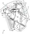
图3描绘了根据一个实施方案的图1和图2的样品管理器的内部的透视图。Figure 3 depicts a perspective view of the interior of the sample manager of Figures 1 and 2, according to one embodiment.
图4描绘了根据一个实施方案的处于第一校准位置的图1和图2的样品管理器的内部的透视图。4 depicts a perspective view of the interior of the sample manager of FIGS. 1 and 2 in a first calibration position, according to one embodiment.
图5描绘了根据一个实施方案的处于第二校准位置的图1和图2的样品管理器的内部的透视图。5 depicts a perspective view of the interior of the sample manager of FIGS. 1 and 2 in a second calibration position, according to one embodiment.
图6描绘了根据一个实施方案的从样品管理器的内部拆卸的针臂的透视图。6 depicts a perspective view of a needle arm removed from the interior of a sample manager, according to one embodiment.
图7描绘了根据一个实施方案的拆卸了针组件的图6的针臂的透视图。7 depicts a perspective view of the needle arm of FIG. 6 with the needle assembly disassembled, according to one embodiment.
图8描绘了根据一个实施方案的图6的针臂的侧视图。Figure 8 depicts a side view of the needle arm of Figure 6 according to one embodiment.
图9描绘了根据一个实施方案的图6和图8的针臂的顶视图。Figure 9 depicts a top view of the needle arm of Figures 6 and 8, according to one embodiment.
图10描绘了根据一个实施方案的在图9的箭头10-10处截取的图6、图8和图9的针臂的侧视截面图。10 depicts a side cross-sectional view of the needle arm of FIGS. 6 , 8 and 9 taken at arrow 10 - 10 of FIG. 9 , according to one embodiment.
具体实施方式Detailed ways
在本说明书中提到“一个实施方案”或“实施方案”表示结合实施方案描述的特定特征、结构或特性包括在本教导的至少一个实施方案中。对本说明书内的特定实施方案的引用不一定都指代相同的实施方案。Reference in this specification to "one embodiment" or "an embodiment" means that a particular feature, structure, or characteristic described in connection with the embodiment is included in at least one embodiment of the present teachings. References to a particular embodiment within this specification are not necessarily all referring to the same embodiment.
现在将参考如附图所示的本教导的示例性实施方案来更详细地描述本教导。虽然结合各种实施方案和示例描述了本教导,但是本教导不旨在限制于此类实施方案。相比之下,本教导涵盖各种替代、修改和等同物,如本领域的技术人员将理解。能够使用本文教导的普通技术人员将认识到在如本文所述的本公开的范围内的附加实施方式、修改和实施方案,以及其他使用领域。The present teachings will now be described in more detail with reference to exemplary embodiments of the present teachings as illustrated in the accompanying drawings. While the present teachings are described in connection with various embodiments and examples, the present teachings are not intended to be limited to such embodiments. In contrast, the present teachings encompass various alternatives, modifications, and equivalents, as will be understood by those skilled in the art. Those of ordinary skill having access to the teachings herein will recognize additional implementations, modifications, and implementations, as well as other areas of use, within the scope of the present disclosure as described herein.
如本文所述,在执行液相色谱运行之前,技术人员将容纳样品的瓶阵列装载到样品瓶支架上、将样品瓶支架放置到抽屉上以及将抽屉滑入样品管理器系统的热处理室的样本盘内的舱中。样品管理器系统包括样品递送系统,该样品递送系统被构造成将样品从样品瓶支架转移到色谱流动流中。热处理室包括取样机构,该取样机构包括具有改进的样品容量和取样准确度的旋转样品盘。作为取样机构的一部分的取样针位于旋转针臂上,该旋转针臂与旋转样品盘相结合在样品盘内的舱上方提供完整的针覆盖。整个针臂在热处理室内定位和设定尺寸,使得针臂可从热处理室的前门移除以便于维修。旋转针臂和旋转样品盘上的编码器保持足够的分辨率以进行准确取样。这些旋转针臂可以使用确保准确度的校准过程来校准。As described here, prior to performing an LC run, the technician loads the vial array containing the samples onto the vial rack, places the vial rack onto the drawer, and slides the drawer into the sample manager system's thermal chamber. In the cabin of the plate. The sample manager system includes a sample delivery system configured to transfer the sample from the vial holder into the chromatographic flow stream. The thermal processing chamber includes a sampling mechanism that includes a rotating sample disk with improved sample capacity and sampling accuracy. The sampling needle, which is part of the sampling mechanism, is located on a rotating needle arm which in combination with the rotating sample tray provides complete needle coverage over the compartment within the sample tray. The entire needle arm is positioned and dimensioned within the thermal processing chamber such that the needle arm is removable from the front door of the thermal processing chamber for maintenance. Encoders on the rotating needle arm and rotating sample disk maintain sufficient resolution for accurate sampling. These rotating needle arms can be calibrated using a calibration process that ensures accuracy.
本文所述的样品递送系统和样品管理器热处理室的特征可以适用于被构造成将样品递送到色谱流动流中的任何液相色谱系统。作为一个示例,图1示出了用于将混合物分离成其组分的液相色谱系统10的实施方案。液相色谱系统10包括溶剂递送系统12,该溶剂递送系统通过管材16与样品管理器14(也称为注射器或自动取样机)流体连通。样品管理器14与色谱柱18流体连通。检测器21例如质谱仪与柱18流体连通以接收洗脱。The features of the sample delivery system and sample manager thermal processing chamber described herein can be applied to any liquid chromatography system configured to deliver a sample into a chromatographic flow stream. As an example, Figure 1 shows an embodiment of a
溶剂递送系统12包括泵送系统20,该泵送系统与溶剂贮存器22流体连通,泵送系统20通过管材24从该溶剂贮存器抽取溶剂(液体)。在一个实施方案中,泵送系统20由低压混合梯度泵送系统体现,该低压混合梯度泵送系统具有两个以流体方式串联连接的两个泵。在低压梯度泵送系统中在泵之前发生溶剂的混合,并且溶剂递送系统12具有混合器26,该混合器与溶剂贮存器22流体连通以按计量比例接收各种溶剂。溶剂(移动相)组合物的这种混合随时间而变化(即,梯度)。The
泵送系统20与混合器26流体连通,以从其中抽取连续梯度流以便递送到样品管理器14。可以用于实现溶剂递送系统12的溶剂递送系统的示例包括但不限于由马萨诸塞州米尔福德的沃特世公司(Waters Corp. of Milford, Mass)制造的ACQUITY二元溶剂管理器和ACQUITY四元溶剂管理器。Pumping
样品管理器14可包括注射器阀28,该注射器阀具有样品环30。样品管理器14在两种状态中的一种状态下操作:装载状态和注射状态。在装载状态下,注射器阀28的位置使得样品管理器将样品32装载到样品环30中。从样品瓶支架所容纳的瓶中抽取样品32。本文中的“样品瓶支架”是指被配置为承载样品瓶的任何装置,诸如孔板、样品瓶支架等。在注射状态下,注射器阀28的位置改变,使得样品管理器14将样品环30中的样品从溶剂递送系统引入到连续流动移动相中。因此,移动相将样品载送到柱18中。在其他实施方案中,可利用流通针式(FTN)代替固定定量环样品管理器。使用FTN方法,可将样品拉入针中,然后可将针移动到密封件中。然后可切换阀以使针与溶剂递送系统成一直线。
液相色谱系统10进一步包括数据系统34,该数据系统与溶剂递送系统12和样品管理器14进行信号通信。数据系统34具有处理器36和交换机38(例如,以太网交换机),该交换机用于处理溶剂递送系统12和样品管理器14之间的信号通信。各种系统和仪器之间的信号通信可以是电的或光的,使用无线或有线传输进行。主机计算系统40与数据系统34通信,技术人员可以通过该数据系统将各种参数和配置文件(例如,进气速度配置文件)下载到数据系统34。
图2示出了液相色谱系统10的透视图,该液相色谱系统包括样品管理器14、检测器21、色谱柱18、溶剂递送系统12和溶剂22。样品管理器14、检测器21、色谱柱18、溶剂递送系统12中的每一者均可包括壳体或主体,在该壳体或主体内可容纳有各种特征,诸如数据系统34、样品环30和注射器阀28、泵送系统20、混合器26和管材24。各种部件12、14、18、19、21、22可与流体管互连并且与系统的数据系统34进行信号通信。液相色谱系统10被示出为具有溶剂递送系统12、样品管理器14、色谱柱18、检测器21和用于将溶剂22保持堆叠在一起的托盘。FIG. 2 shows a perspective view of
图3描绘了根据一个实施方案的图1和图2的样品管理器14的取样机构100的透视图。如图所示,取样机构100包括附接到基准基座112的样品盘110。竖直框架114附接并垂直于基准基座112延伸。针臂116附接到竖直框架114。针臂116包括穿刺针122(如图4所示)和作为样品递送系统的一部分的样品针(未示出),该样品递送系统与溶剂递送系统12流体连通。样品针可以被构造成从样品瓶33(如图2所示)获得或以其他方式抽取样品32。此后,液相色谱系统10的样品递送系统被构造成将样品32转移到色谱流动流中并转移到位于样品递送系统下游的柱18,并且然后转移到位于柱18下游的检测器21。样品瓶33可以是位于样品盘110上的多达四个样品瓶支架(未示出)内的许多小瓶中的一个小瓶。FIG. 3 depicts a perspective view of
样品盘110可以被构造成围绕第一竖直轴线A1旋转360度,而针臂116被构造成围绕第二竖直轴线A2至少部分地旋转。这两个旋转可以在样品盘110内的所有样品瓶支架124上通过针臂116提供足够覆盖。旋转针臂116与样品盘110的旋转相结合可以由此被构造成将样品针122移动到适当位置以接近样品盘110上的任何位置,该位置将样品瓶33保持在样品瓶支架内。The
如图所示,样品盘110包括圆形框架,该圆形框架包括四个舱–第一支架舱126a、第二支架舱126b、第三支架舱126c和第四支架舱126d。支架舱126a、126b、126c、126d围绕圆形样品盘110的周边等距设置。换句话说,支架舱126a、126b、126c、126d围绕圆形样品盘110彼此周向90度地设置。如上所述,旋转针臂116与样品盘110的旋转相结合被构造成将样品针122直接移动到由相应支架舱126a、126b、126c、126d的相应周边覆盖的任何位置上方。盘可以包括如图所示的四个舱,但在其他实施方案中还可以包括三个舱或延伸到甚至多于四个舱。舱可以彼此等距,或者可以围绕圆形样品盘110的圆周以其他方式交错。As shown, the
支架舱126a、126b、126c、126d中的每一者被示出为滑入和滑出舱抽屉接纳器128a、128b、128c、128d的抽屉。支架舱126a、126b、126c、126d可以被构造成从相应舱抽屉接纳器128a、128b、128c、128d径向向外拉动,以便便于将样品瓶支架装载进和装载出样品盘的前门130(如图2所示)。支架舱126a、126b、126c、126d和相应舱抽屉接纳器128a、128b、128c、128d的集成可以被构造成在支架舱126a、126b、126c、126d与舱抽屉接纳器128a、128b、128c、128d完全断开连接之前停止支架舱126a、126b、126c、126d。另选地,取样机构100的边框可以包括防止支架舱126a、126b、126c、126d与舱抽屉接纳器128a、128b、128c、128d完全断开连接的结构。Each of the
支架舱126a、126b、126c、126d各自被配置用于接纳样品瓶支架。样品管理器100可以被配置为接收和处理所有四个支架舱126a、126b、126c、126d内的样品。除了经由轨道系统滑入和滑出舱抽屉接纳器128a、128b、128c、128d之外,支架舱126a、126b、126c、126d可以包括位于下方的磁体,该磁体被构造成将样品瓶支架磁性地保持在支架舱126a、126b、126c、126d内的适当位置。对应磁体可以位于支架舱126a、126b、126c、126d内的径向向内位置,以进一步确保支架舱126a、126b、126c、126d相对于舱抽屉接纳器128a、128b、128c、128d正确地就位(即完全插入)。片簧132可以被构造成将所接纳的样品盘朝向相应支架舱126a、126b、126c、126d的最左壁偏置,而磁性结构将所接纳的样品盘抵靠相应支架舱126a、126b、126c、126d的径向向内壁保持。The
样品盘110包括用于接纳柱136的中间开口134,样品盘110围绕该柱被构造成围绕竖直轴线A1旋转。样品盘110还包括附加开口136,该附加开口围绕周边设置在支架舱126a、126b、126c、126d之间,该附加开口被构造成接纳并保持较大单个单独的小瓶(未示出)或其他样品。针臂116(和其针)可以被构造成定位在周边附加开口136中的每一个附加开口上方。The
样品盘110被示出为安装到基准基座112。基准基座112可以是安装到样品管理器14内的热处理室框架(未示出)的金属板。基准基座112可以包括开口,偏转限制柱120穿过该开口延伸。偏转限制柱120可以被构造成防止样品盘110在停止之前相对于基准基座112偏转超过特定距离。偏转限制柱120可以键接到样品盘110的底部中的通道,并且可以充当轴承以允许样品盘110围绕基准基座112旋转。样品盘110围绕基准基座112的旋转可由设置在靠近样品盘110的周边的基准基座112上的马达150产生。基准基座112还包括多个螺纹开口,这些螺纹开口被构造成接纳用于在每一侧处附接直角托架118的螺栓。直角托架118可以被构造成以竖直定向将竖直框架114附接到基准基座112。编码器(未示出)可以进一步附接到样品盘110以维持样品盘110相对于基准基座112的定位。
竖直框架114附接到基准基座112,使得竖直框架114延伸穿过样品盘110的圆周。考虑到该位置在样品盘110上方,竖直框架114包括开口140(如图4所示)或切口,样品盘110和任何所接纳的样品瓶载体124a、124b以及任何所接纳的样品瓶33被构造成穿过该开口或切口。开口140的尺寸足够高以接纳高样品瓶支架124b而不会引起干扰。竖直框架114在开口140上方形成表面,在该表面上安装针臂116。A
针臂116被示出为包括驱动机构142和马达144。马达144被构造成围绕旋转皮带148的轴线旋转,该皮带继而旋转滑轮152。滑轮152的旋转可以被构造成使针臂116围绕第二竖直轴线A2旋转。针臂116的旋转可以是相对于样品盘110的旋转的独立旋转,并且可以是围绕与样品盘110围绕其旋转的竖直轴线A1不同的竖直轴线A2的旋转。
现在参见图4,在第一校准位置中示出了根据一个实施方案的图1和图2的样品管理器14的内部的透视图。图4所示的第一校准位置是针臂116相对于图3所示的位置围绕第二竖直轴线A2逆时针旋转的位置。如图所示,轴154延伸穿过滑轮152,该滑轮附接到并被构造成与滑轮152一起旋转。轴154连接到旋转板155,该旋转板被构造成与轴154一起旋转并且使针组件190旋转。轴154包括偏置弹簧232。可移除的针臂壳体158附接到竖直框架114。可移除的针臂壳体158包括刚好从竖直框架114中的开口140上方延伸的水平板160。水平板160包括衬套156,该衬套被构造成接纳轴154的基座并且维持轴154与第二竖直轴线A2对准。针臂壳体158用多个可触及螺栓162可移除地附接到竖直框架114。可触及螺栓162可通过样品管理器14的门130触及。这可以允许整个竖直框架114和针臂116以及其所有部件在维护或零件更换期间易于通过门130移除。Referring now to FIG. 4 , a perspective view of the interior of the
针臂116还包括磁编码器146。磁编码器146可以被构造成将针臂116的旋转位置确定为样品针122的准确定位所需的任何公差。同样,马达150可以配备有用于确定样品盘110的旋转位置的编码器。系统中的两个编码器可以与控制系统(例如,数据系统34)通信,用于校准和控制针臂116和样品盘110的移动。虽然可以利用磁编码器,但是设想了其他编码器,诸如光学编码器。The
针臂116被示出为包括两个单独的马达164a、164b,这两个单独的马达被构造成旋转两个单独的驱动轴。第一马达164a被构造成使第一驱动轴236(如图6和图8所示)旋转,该第一驱动轴在穿刺针122上进行移动。第二马达164b被构造成使第二驱动轴238(如图6和图8所示)旋转,该第二驱动轴在样品针(未示出)上进行移动。第一马达164a和第二马达164b可以附接到针臂116,使得马达164a、164b与针臂116一起旋转。穿刺针122可以与样品针结合操作,以便穿刺覆盖样品瓶的任何材料或膜。两个马达164a、164b可以被配置为独立地操作,并且可以由控制系统和/或数据系统34控制和编程以用于操作例程。
针臂的针组件190包括具有两个可触及螺栓194的板192,该可触及螺栓可由打开样品管理器14的门130的技术人员触及。在拧松可触及螺栓194后,技术人员可以从针机构基座230移除针组件190和附接的马达164a、164b。针组件190和马达164a、164b可以通过样品管理器14的门130移除而不移除针机构基座230。类似地,马达164a、164b可以通过从板192移除一个或多个可触及马达螺栓196来容易地从针臂116移除。这可以允许马达164a、164b容易地更换或移除以通过样品管理器14的前门130进行维护而不移除针臂116的其他部件。The
样品递送系统还可以包括位于样品针与液相色谱柱18之间的流体管(未示出)。流体管可以包括盘绕部分,该盘绕部分被构造成在针臂116围绕第二竖直轴线A2旋转期间伸展和收缩。盘绕部分可以在穿刺针122上方的针臂116的顶部与竖直框架114之间延伸。盘绕部分可以在针臂116旋转远离竖直框架114时展开,并且在针臂116朝向竖直框架114旋转时回缩。流体管的盘绕部分可以是螺旋的、弯曲的或以其他方式卷曲的,以便以不干扰样品管理器14内的各种部件的其他移动的可预测方式提供纵向伸展和收缩。The sample delivery system may also include a fluid tube (not shown) between the sample needle and the
重新参见图3,针臂116在该视图中被示出为已经旋转到原始位置,由此连接到、联接到或集成到竖直框架114中的突出止动件182与针组件190接触。原始位置可以是旋转到停止点的位置,针臂116可能无法旋转超过该停止点。如图所示,在原始位置处,针臂116沿顺时针方向旋转到最大旋转点,由此针臂116被突出止动件182停止进一步顺时针旋转。Referring back to FIG. 3 ,
附接到基准基座112的可以是从位于原始位置或地点附近的基准基座112中的开口170延伸的针清洗系统(未示出)。针清洗系统可以包括多个液体源管,每个液体源管被构造成当针在针清洗系统上方移动时引入水和/或其他清洁剂以清洗样品针122和/或穿刺针。清洗过程可以包括例如从液体源管中的第一液体源管向样品针122提供第一清洁剂,并且然后在液体源管中的第二液体源管上方移动样品针122,以用水清洁。设想了适合于清洗针臂116中的针的其他清洗过程和结构。Attached to the
针臂116可以被构造成围绕旋转轴154和第二轴线A2旋转一定量,该量允许针组件190完全覆盖样品盘110的整个工作部分。在所示的实施方案中,针臂116可以被构造成旋转超过45度但小于90度。在其他实施方案中还设想了除了所示的旋转运动以外的额外旋转运动(即等于或大于90度)。
参见图4和图5,示出了根据一个实施方案的图1和图2的样品管理器14的内部,其中针臂116位于两个校准位置中。在各种设想的实施方案中,设想了各种校准系统。图4和图5示出了一个示例性校准系统,其中数据系统34和/或样品管理器控制系统可以被配置为校准取样机构100以使用。一个校准过程可以包括如图4所示的第一步骤,该第一步骤为移动样品盘110和针臂116以将针与样品盘中的第一开口210对准,然后记录样品盘110和针臂116中的每一者的第一编码器位置。例如,针臂116可以从原始位置(如图3所示)逆时针移动到图4所示的位置,使得穿刺针122(或样品针)直接位于第一开口210上方。Referring to FIGS. 4 and 5 , the interior of the
然后,校准过程可以包括将样品盘110和针臂116移动到图5所示的位置的第二步骤,以便将穿刺针122(或样品针)与样品盘中的第二开口220对准。然后,校准过程可以包括记录样品盘110和针臂116中的每一者的第二编码器位置。利用已知的第一编码器位置和第二编码器位置,数据系统34和/或样品管理器控制系统可以被配置为反算取样机构100的几何参数,从而校准样品盘110和针臂116的移动和位置。位置准确度可比典型的现有技术校准过程更精确,因为上文所描述的本发明方法不依赖于假定的几何质量处于一定水平的公差内。The calibration process may then include a second step of moving the
图6描绘了根据一个实施方案的从样品管理器14的内部拆卸的针臂116的透视图。如图所示,针臂116包括基座230,该基座能够可移除地附接到液相色谱系统10的样品管理器14。针臂116还包括针组件190,该针组件可移除地附接到基座230。基座230从样品管理器14上的可移除性以及针组件190从基座230上的可移除性各自可以通过可触及螺栓、螺钉、销或其他容易触及的、可接合的和/或可解脱的联接装置来提供。如本文所述的这些部件中的每个部件的可附接的可移除性提供了通过样品管理器14的前门对针臂116的部件进行维修和更换的容易性。此外,如上所述,针臂116包括足够的结构以在针臂116附接在样品管理器14内时提供臂围绕竖直轴线的旋转移动。6 depicts a perspective view of
图7描绘了根据一个实施方案的拆卸了针组件190的图6的针臂的基座230的透视图。基座230包括可移除的针臂壳体158。可移除的针臂壳体158提供用于将基座230附接到液相色谱系统10的样品管理器14的内部的框架,诸如通过将可移除的针臂壳体158附接到竖直框架114。可移除的针臂壳体158包括平坦竖直表面,该平坦的竖直表面被构造成邻接竖直框架114的平坦竖直表面。如图6所示,位于针臂壳体158的背表面上的多个对准销234与可触及螺栓162协作作用,以将针臂壳体158的平坦竖直表面与竖直框架114的平坦竖直表面附接。虽然未示出,但是竖直框架114可以包括对应的孔或用于接纳可触及螺栓162和对准销234中的每一者的凹形接纳开口。7 depicts a perspective view of the
如图所示,基座230包括被构造成围绕竖直轴线A2旋转的轴154。可移除的针臂壳体158被构造成将轴154保持在顶部位置和底部位置两者处,同时允许轴154围绕可移除的针臂壳体158旋转。具体地,可移除的针臂壳体158包括下水平板160和从可移除的针臂壳体158的平坦竖直表面延伸的上水平板161。衬套156在下水平板160处设置有开口,允许轴154在其中旋转。As shown,
基座230还包括马达144、驱动机构142、皮带148、滑轮152和旋转板155。马达144的驱动机构142可以是马达144被构造成致使其旋转的驱动轴等。驱动机构142的旋转进一步引起皮带148的移动,从而引起滑轮152的旋转,该滑轮附接到竖直轴154。旋转板155附接到轴154,并且被构造成随着轴154的旋转而旋转。
图8描绘了根据一个实施方案的针臂116的侧视图,该针臂包括针组件190和基座230两者。参见图6的透视图和图8的侧视图,示出了基座230,其包括马达144、磁编码器146、壳体158和旋转板155中的每一者。针组件190包括壳体264或其他主体,针组件190的部件附接在该壳体或其他主体上。如图所示,针组件190的壳体264的板192附接到基座230,并且具体地附接到旋转板155。FIG. 8 depicts a side view of
针组件190包括驱动系统。驱动系统包括第一马达,该第一马达具有附接到壳体264的板192的顶部的第一驱动轴236。针组件190还包括第二马达164b,该第二马达具有附接到壳体264的板192的底部的第二驱动轴238。第一马达164a和第一驱动轴236被构造成经由在穿刺针轴线260上施加竖直运动或移动来在穿刺针122上施加竖直运动或移动。同样,第二马达164b和第二驱动轴238被构造成经由在样品针轴线258上施加竖直运动或移动来在样品针261上施加竖直运动或移动。
此外,汽提器支脚262附接到汽提器支脚轴线268,该汽提器支脚轴线包括具有弹簧机构的弹簧加载端266。弹簧机构可以被构造成在汽提器支脚262和汽提器脚轴线268的向下移动期间压缩。在使用中,汽提器支脚262可以接触样品瓶(未示出)的顶部,之后可以将穿刺针122推动通过样品瓶的保护膜。在穿刺针122已经穿刺此顶部保护膜之后,穿刺针122必须从样品瓶和保护膜缩回。汽提器支脚262可以被构造成在样品瓶的顶部提供向下的力,使得穿刺针122可以适当地缩回而不会粘附到样品瓶的保护膜上。汽提器支脚262包括开口,穿刺针122被构造成在穿刺期间延伸穿过该开口。Additionally, a
如图6所示,汽提器支脚轴线268可经由两个联接器270相对于穿刺针轴线260移动。联接器270可以包括位于汽提器支脚轴线268中的顶部细长竖直开口和底部细长开口,顶部和底部相应销延伸穿过该顶部细长竖直开口和该底部细长开口。顶部和底部相应销附接到穿刺针轴线260的穿刺针联接表面272。顶部和底部细长竖直开口与销配合,使得汽提器支脚轴线268和穿刺针轴线260以允许汽提器支脚轴线268与穿刺针轴线260之间的竖直移动的方式连接或以其他方式联接。汽提器支脚轴线268与穿刺针轴线260之间的最大竖直移动由汽提器支脚轴线268中的顶部和底部细长竖直开口的竖直长度限定。As shown in FIG. 6 , the
样品针261沿着与穿刺针122相同的竖直轴线定位。样品针261可以是直径小于穿刺针122的针,使得样品针261被构造成延伸穿过穿刺针122的较大直径开口。针保持器244位于样品针轴线258的顶部处。样品针保持器244可以被构造成在将样品针261与穿刺针122对准的位置处可移除地接纳样品针261。样品针保持器244附接到样品针轴线258,使得样品针保持器244并且由此样品针261在样品针轴线258被第二马达164b和其第二驱动轴238驱动或移动时移动。Sample needle 261 is positioned along the same vertical axis as piercing
图9描绘了根据一个实施方案的针臂116的顶视图。参考图6的透视图和图9的俯视图两者,示出了针臂传感器系统。传感器系统包括样品针原点传感器240、穿刺针原点传感器254和顶部传感器252。传感器系统还可以包括印刷电路板246,该印刷电路板被配置为向/从传感器系统中的各种传感器240、254、252提供电力、控制信号和/或通信信号。印刷电路板246可以是柔性电路板,该柔性电路板被构造成随着针组件190围绕竖直轴154的旋转而弯曲。印刷电路板246可以能够执行其功能而不损失其信号和/或导电完整性,同时通过针组件190围绕竖直轴154的旋转在针臂116的整个生命周期中来回弯曲。传感器系统和/或印刷电路板246和传感器240、254、252可以与诸如数据系统34的控制系统可操作地通信,使得感测到的信息被提供给数据系统34以进行处理。Figure 9 depicts a top view of the
样品针原点传感器240被配置为感测样品针轴线258的移动和/或确定样品针轴线258何时到达原始(顶部)位置。样品针原点传感器240可以被配置为感测和/或确定样品针261已经在竖直方向上移动预定距离到样品针原始位置。样品针保持器244连接到样品针轴线258并且与样品针轴线258一起移动。样品针保持器244包括延伸突出部242,该延伸突出部被构造成在样品针原点传感器240的两个叉状物之间移动。因此,当样品针轴线258移动到顶部原始位置时,延伸突出部242定位在样品针原点传感器240的两个叉状物之间,从而感测样品针轴线258处于原始位置。连接导体248在印刷电路板246与样品针原点传感器240之间延伸,该样品针原点传感器被配置为向和从样品针原点传感器240提供电力和/或其他控制信号或通信信号。The sample
穿刺针原点传感器254被配置为感测穿刺针轴线260的移动和/或确定穿刺针轴线260何时到达原始(顶部)位置。穿刺针原点传感器254可以被配置为感测和/或确定穿刺针122已经在竖直方向上移动预定距离到穿刺针原始位置。穿刺针轴线260,并且具体地,其穿刺针联接表面272包括延伸突出部256,该延伸突出部被构造成在穿刺针原点传感器254的两个叉状物之间移动。因此,当穿刺针轴线260移动到顶部原始位置时,延伸突出部256定位在穿刺针原点传感器254的两个叉状物之间,从而感测穿刺针轴线260处于原始位置。连接导体248在印刷电路板246与穿刺针原点传感器254之间延伸,该穿刺针原点传感器被配置为向和从穿刺针原点传感器254提供电力和/或其他控制信号或通信信号。
传感器系统的顶部传感器252被配置为感测汽提器支脚262何时被压缩预定量。此预定量可以对应于通过样品瓶的顶部作用在汽提器支脚262上的力。服务回路250可以从印刷电路板246延伸到顶部传感器252,以向和从顶部传感器252提供电力和/或其他控制信号或通信信号。顶部传感器252可以是汽提器支脚移动传感器,该汽提器支脚移动传感器被配置为确定汽提器支脚262已经沿竖直方向移动预定距离。The
图10描绘了根据一个实施方案的在图9的箭头10-10处截取的针臂116的侧视截面图。如图所示,驱动系统可以包括用于将驱动轴236、238的旋转运动转换成轴线258、260的竖直线性运动的系统。第一马达164a和第二马达164b可以彼此独立地操作,使得穿刺针122和样品针261能够独立地竖直运动。顶部驱动轴236被示出为从第一马达164a延伸穿过壳体264的板192中的开口。类似地,底部驱动轴238被示出为从第二马达164b延伸穿过壳体264的板192中的开口。如图所示,顶部驱动轴236附接到接合结构274,该接合结构被构造成绕过样品针轴线258并与穿刺针轴线260接合,以将驱动轴236的旋转运动转换成穿刺针轴线260的线性竖直运动。类似地,底部驱动轴238附接到接合结构276,该接合结构被构造成与样品针轴线258接合,以将驱动轴238的旋转运动转换成样品针轴线258的线性竖直运动。Figure 10 depicts a side cross-sectional view of the
虽然已经参考特定实施方案示出和描述了本发明,但是本领域的技术人员应理解,在不脱离如所附权利要求中叙述的本发明的实质和范围的情况下,可以在形式和细节上进行各种改变。While the present invention has been shown and described with reference to particular embodiments, it will be understood by those skilled in the art that changes may be made in form and detail without departing from the spirit and scope of the invention as set forth in the appended claims. Make various changes.
Claims (18)
Applications Claiming Priority (3)
| Application Number | Priority Date | Filing Date | Title |
|---|---|---|---|
| US202062990613P | 2020-03-17 | 2020-03-17 | |
| US62/990613 | 2020-03-17 | ||
| PCT/US2021/022535WO2021188519A1 (en) | 2020-03-17 | 2021-03-16 | Sample manager, system and method |
Publications (1)
| Publication Number | Publication Date |
|---|---|
| CN115667908Atrue CN115667908A (en) | 2023-01-31 |
Family
ID=75581599
Family Applications (1)
| Application Number | Title | Priority Date | Filing Date |
|---|---|---|---|
| CN202180035898.4APendingCN115667908A (en) | 2020-03-17 | 2021-03-16 | Sample managers, systems and methods |
Country Status (4)
| Country | Link |
|---|---|
| US (1) | US11879875B2 (en) |
| EP (1) | EP4121753A1 (en) |
| CN (1) | CN115667908A (en) |
| WO (1) | WO2021188519A1 (en) |
Families Citing this family (2)
| Publication number | Priority date | Publication date | Assignee | Title |
|---|---|---|---|---|
| CN115667908A (en) | 2020-03-17 | 2023-01-31 | 沃特世科技公司 | Sample managers, systems and methods |
| EP4585920A2 (en)* | 2020-03-17 | 2025-07-16 | Waters Technologies Corporation | Needle drive |
Citations (11)
| Publication number | Priority date | Publication date | Assignee | Title |
|---|---|---|---|---|
| US4447395A (en)* | 1982-02-12 | 1984-05-08 | The United States Of America As Represented By The Secretary Of The Army | Sampling device |
| US4951513A (en)* | 1987-12-14 | 1990-08-28 | Ajinomoto Company, Inc. | Automatic preparation apparatus and filter therefor |
| EP0724901A1 (en)* | 1995-02-02 | 1996-08-07 | ISCO, Inc. | Apparatus and method for supercritical fluid extraction or supercritical fluid chromatography |
| US5660727A (en)* | 1994-06-14 | 1997-08-26 | Dionex Corporation | Automated analyte supercritical fluid extraction apparatus |
| US5682026A (en)* | 1996-03-01 | 1997-10-28 | Waters Investments Limited | Multiple carousel carrier and carousel handling mechanism |
| JP2009222398A (en)* | 2008-03-13 | 2009-10-01 | Sekisui Chem Co Ltd | Liquid chromatograph apparatus and liquid chromatography |
| US20110120213A1 (en)* | 2008-08-01 | 2011-05-26 | Shiseido Company, Ltd. | Sample injector, sample injecting method, and liquid chromatograph |
| WO2015079873A1 (en)* | 2013-11-27 | 2015-06-04 | 株式会社島津製作所 | Automatic sample injection device |
| CN107430103A (en)* | 2015-05-28 | 2017-12-01 | 株式会社岛津制作所 | Autosampler |
| US20190383776A1 (en)* | 2018-06-14 | 2019-12-19 | Waters Technologies Corporation | Sample organizer, tray, system and method |
| CN110753842A (en)* | 2017-06-19 | 2020-02-04 | 沃特世科技公司 | Online dilution of liquid chromatography systems using sample metering pumps |
Family Cites Families (42)
| Publication number | Priority date | Publication date | Assignee | Title |
|---|---|---|---|---|
| US3918913A (en) | 1974-12-02 | 1975-11-11 | Lilly Co Eli | Sampler-injector for liquid chromatography |
| DE2826275A1 (en) | 1978-06-15 | 1979-12-20 | Bna Augustin Gmbh & Co | DEVICE FOR SAMPLE DISTRIBUTION FOR LIQUID EXAMINATION MATERIAL FOR ANALYSIS |
| JPH0128456Y2 (en) | 1981-06-04 | 1989-08-30 | ||
| US4713974A (en)* | 1986-04-18 | 1987-12-22 | Varian Associates, Inc./Scientific Systems, Inc. | Autosampler |
| JPH0781996B2 (en) | 1988-08-27 | 1995-09-06 | 株式会社日立製作所 | Auto sampler |
| US5531323A (en) | 1992-06-22 | 1996-07-02 | Kelson; Lance P. | Cooperative medical sampling and needle removal devices |
| US5352612A (en) | 1993-02-09 | 1994-10-04 | Baxter Diagnostics Inc. | Method and apparatus for the stepwise movement of items |
| US6790674B2 (en) | 1993-03-30 | 2004-09-14 | Isco, Inc. | Sampler |
| US5482207A (en) | 1994-04-29 | 1996-01-09 | Life Medical Technologies, Inc. | System for facilitating the removal and safe disposition of medical needles |
| US5993627A (en) | 1997-06-24 | 1999-11-30 | Large Scale Biology Corporation | Automated system for two-dimensional electrophoresis |
| DE69832488T2 (en)* | 1998-05-25 | 2006-06-01 | Agilent Technologies, Inc. (n.d.Ges.d.Staates Delaware), Palo Alto | Sample injection device for a high performance liquid chromatograph |
| JP3422262B2 (en)* | 1998-08-28 | 2003-06-30 | 株式会社島津製作所 | Sample cooling device |
| IL126742A0 (en) | 1998-10-26 | 1999-08-17 | Ultraguide Ltd | Needle and sensor adapters for medical systems |
| US7008599B1 (en) | 1999-05-10 | 2006-03-07 | Smithkline Beecham Corporation | High throughput crystal form screening workstation and method of use |
| FR2810407B1 (en) | 2000-06-16 | 2002-08-02 | Philippe Escal | APPARATUS FOR THE ANALYSIS OF SAMPLES |
| US6760679B1 (en) | 2001-01-26 | 2004-07-06 | Ta Instruments-Waters, Llc | Method and apparatus for positional calibration of a thermal analysis instrument |
| GB2376892B (en) | 2001-06-28 | 2004-07-07 | Stephen Francis Gerard Cooley | Medical needle removal device |
| DE10219790C1 (en) | 2002-05-03 | 2003-10-23 | Gerstel Systemtechnik Gmbh | Sample handling device, for chromatograph, comprises moving arm for holder moving between hanging position on receiver opposite arm and position on arm |
| US6745898B2 (en) | 2002-05-15 | 2004-06-08 | Future Top Medical Environment Technic Co., Ltd. | Needle extracting and recovering device |
| US7628954B2 (en) | 2005-05-04 | 2009-12-08 | Abbott Laboratories, Inc. | Reagent and sample handling device for automatic testing system |
| US8776621B2 (en) | 2009-03-06 | 2014-07-15 | Dionex Corporation | Fluid sample delivery system and method |
| US8293100B2 (en) | 2009-03-13 | 2012-10-23 | Terrasep, Llc | Methods and apparatus for centrifugal liquid chromatography |
| EP2411792B1 (en) | 2009-03-24 | 2014-12-10 | PerkinElmer Health Sciences, Inc. | System and auto-alignment method for determining position using a discrete contact probe |
| EP2261676B8 (en) | 2009-06-12 | 2015-03-18 | CTC Analytics AG | Tool for handling a sample |
| WO2012096649A1 (en) | 2011-01-11 | 2012-07-19 | Waters Technologies Corporation | Apparatus for reducing variation in sample temperatures in a liquid chromatography system |
| US9733221B2 (en) | 2011-06-09 | 2017-08-15 | Agilent Technologies, Inc. | Injection needle cartridge with integrated sealing force generator |
| ES2764774T3 (en) | 2013-03-13 | 2020-06-04 | Siemens Healthcare Diagnostics Products Gmbh | Retention device for a pipetting needle |
| JP6191687B2 (en) | 2013-03-29 | 2017-09-06 | 株式会社島津製作所 | Sample cooling device and autosampler equipped with the same |
| WO2014162921A1 (en)* | 2013-04-01 | 2014-10-09 | 株式会社島津製作所 | Autosampler |
| WO2015177857A1 (en)* | 2014-05-20 | 2015-11-26 | 株式会社島津製作所 | Sample introduction system |
| US9816971B2 (en) | 2014-09-08 | 2017-11-14 | Waters Technologies Corporation | Controllable injector sample dilution for a liquid chromatography system |
| CN208984092U (en) | 2015-04-30 | 2019-06-14 | 珀金埃尔默健康科学股份有限公司 | Autosamplers, autoloaders, and systems and devices using them |
| WO2017043192A1 (en)* | 2015-09-09 | 2017-03-16 | 株式会社 日立ハイテクノロジーズ | Automated analyzer |
| CN205176047U (en) | 2015-12-04 | 2016-04-20 | 苏州北裕环保仪器制造有限公司 | Liquid phase autosampler |
| JP6784196B2 (en)* | 2017-03-03 | 2020-11-11 | 株式会社島津製作所 | Analysis system equipped with a pretreatment device and its pretreatment device |
| JP7124073B2 (en) | 2018-06-04 | 2022-08-23 | 株式会社日立ハイテク | Connection device and laboratory test automation system equipped with the same |
| EP3669987A1 (en) | 2018-12-21 | 2020-06-24 | Roche Diagnostics GmbH | Sample container carrier, laboratory sample distribution system and laboratory automation system |
| WO2020148853A1 (en) | 2019-01-17 | 2020-07-23 | 株式会社島津製作所 | Autosampler for chromatography and fluid chromatography analysis system |
| CN210347441U (en) | 2019-06-13 | 2020-04-17 | 株式会社岛津制作所 | Autosampler |
| CN115667908A (en) | 2020-03-17 | 2023-01-31 | 沃特世科技公司 | Sample managers, systems and methods |
| FR3111789B1 (en) | 2020-06-26 | 2023-12-15 | Bee Healthcare | BLOOD PUNCTURE HEAD FOR AUTOMATIC OR SEMI-AUTOMATIC BLOOD COLLECTION MACHINE |
| WO2023123045A1 (en)* | 2021-12-29 | 2023-07-06 | PerkinElmer Instruments (Suzhou) Co., Ltd. | Automatic positioning of injection needle in an autosampler |
- 2021
- 2021-03-16CNCN202180035898.4Apatent/CN115667908A/enactivePending
- 2021-03-16EPEP21720036.9Apatent/EP4121753A1/enactivePending
- 2021-03-16WOPCT/US2021/022535patent/WO2021188519A1/ennot_activeCeased
- 2021-03-16USUS17/203,021patent/US11879875B2/enactiveActive
Patent Citations (11)
| Publication number | Priority date | Publication date | Assignee | Title |
|---|---|---|---|---|
| US4447395A (en)* | 1982-02-12 | 1984-05-08 | The United States Of America As Represented By The Secretary Of The Army | Sampling device |
| US4951513A (en)* | 1987-12-14 | 1990-08-28 | Ajinomoto Company, Inc. | Automatic preparation apparatus and filter therefor |
| US5660727A (en)* | 1994-06-14 | 1997-08-26 | Dionex Corporation | Automated analyte supercritical fluid extraction apparatus |
| EP0724901A1 (en)* | 1995-02-02 | 1996-08-07 | ISCO, Inc. | Apparatus and method for supercritical fluid extraction or supercritical fluid chromatography |
| US5682026A (en)* | 1996-03-01 | 1997-10-28 | Waters Investments Limited | Multiple carousel carrier and carousel handling mechanism |
| JP2009222398A (en)* | 2008-03-13 | 2009-10-01 | Sekisui Chem Co Ltd | Liquid chromatograph apparatus and liquid chromatography |
| US20110120213A1 (en)* | 2008-08-01 | 2011-05-26 | Shiseido Company, Ltd. | Sample injector, sample injecting method, and liquid chromatograph |
| WO2015079873A1 (en)* | 2013-11-27 | 2015-06-04 | 株式会社島津製作所 | Automatic sample injection device |
| CN107430103A (en)* | 2015-05-28 | 2017-12-01 | 株式会社岛津制作所 | Autosampler |
| CN110753842A (en)* | 2017-06-19 | 2020-02-04 | 沃特世科技公司 | Online dilution of liquid chromatography systems using sample metering pumps |
| US20190383776A1 (en)* | 2018-06-14 | 2019-12-19 | Waters Technologies Corporation | Sample organizer, tray, system and method |
Also Published As
| Publication number | Publication date |
|---|---|
| US20210293761A1 (en) | 2021-09-23 |
| EP4121753A1 (en) | 2023-01-25 |
| WO2021188519A1 (en) | 2021-09-23 |
| US11879875B2 (en) | 2024-01-23 |
Similar Documents
| Publication | Publication Date | Title |
|---|---|---|
| CN115516308B (en) | Needle driver, system and method | |
| CN115667908A (en) | Sample managers, systems and methods | |
| KR900008959B1 (en) | Liquid dispensing device under test | |
| JP5410439B2 (en) | Sample stirring device, liquid chromatography device using the same, and sample container stand | |
| US10252186B2 (en) | Automated solid phase extraction | |
| CN118871780A (en) | Sample managers, systems and methods | |
| CN110741252B (en) | switch valve | |
| US20100233794A1 (en) | Suction device and analysis device | |
| CN114207434B (en) | Method for loading a sample into a sample manager of a chromatography system | |
| US20230384190A1 (en) | Horizontally adjustable sample taker for dissolution apparatus | |
| CN114174822A (en) | Interface module for robotic loading and unloading of sample managers for liquid chromatography | |
| TWI781832B (en) | Edge scanning device and equipment for detecting metal contamination | |
| WO2002071037A2 (en) | Apparatus and method for processing and testing a biological specimen | |
| CN223324552U (en) | Liquid feeding device and sample treatment equipment | |
| CN219377670U (en) | Liquid supply device based on non-contact magnetic stirring | |
| CN117476433B (en) | Quick sample injection device for desorption electrospray ionization mass spectrum | |
| WO2024163334A1 (en) | Liquid chromatography column holder | |
| US20250244209A1 (en) | Calibration of a sampling device for an analytical device | |
| EP2556380B1 (en) | Apparatus for controlling sample position in a liquid chromatography system | |
| US20080089811A1 (en) | Pipetting Device | |
| CN120761663A (en) | Multi-station automatic potentiometric titration analysis system | |
| CN119716122A (en) | Portable biochemical analyzer | |
| WO2025088363A1 (en) | Calibrating an object handling device with a calibration feature | |
| CN117054571A (en) | Sample injection and filtration system of dissolution liquid connection device |
Legal Events
| Date | Code | Title | Description |
|---|---|---|---|
| PB01 | Publication | ||
| PB01 | Publication | ||
| SE01 | Entry into force of request for substantive examination | ||
| SE01 | Entry into force of request for substantive examination |