CN115666697A - Catheters and Treatments - Google Patents
Catheters and TreatmentsDownload PDFInfo
- Publication number
- CN115666697A CN115666697ACN202180035871.5ACN202180035871ACN115666697ACN 115666697 ACN115666697 ACN 115666697ACN 202180035871 ACN202180035871 ACN 202180035871ACN 115666697 ACN115666697 ACN 115666697A
- Authority
- CN
- China
- Prior art keywords
- catheter
- artery
- distal
- curvature
- end side
- Prior art date
- Legal status (The legal status is an assumption and is not a legal conclusion. Google has not performed a legal analysis and makes no representation as to the accuracy of the status listed.)
- Pending
Links
- 238000011282treatmentMethods0.000titleclaimsabstractdescription38
- 210000001367arteryAnatomy0.000claimsabstractdescription49
- 210000002321radial arteryAnatomy0.000claimsabstractdescription47
- 210000000685uterine arteryAnatomy0.000claimsabstractdescription43
- 238000005452bendingMethods0.000claimsabstractdescription38
- 238000000034methodMethods0.000claimsabstractdescription19
- 210000003090iliac arteryAnatomy0.000claimsdescription59
- 210000004204blood vesselAnatomy0.000claimsdescription41
- 206010046798Uterine leiomyomaDiseases0.000claimsdescription12
- 201000010260leiomyomaDiseases0.000claimsdescription12
- 230000002093peripheral effectEffects0.000claimsdescription10
- 210000002307prostateAnatomy0.000claimsdescription8
- 206010004446Benign prostatic hyperplasiaDiseases0.000claimsdescription7
- 208000004403Prostatic HyperplasiaDiseases0.000claimsdescription7
- 201000004240prostatic hypertrophyDiseases0.000claimsdescription7
- 206010051482ProstatomegalyDiseases0.000claimsdescription3
- 210000002376aorta thoracicAnatomy0.000description15
- 230000001225therapeutic effectEffects0.000description15
- 239000003795chemical substances by applicationSubstances0.000description10
- 239000003814drugSubstances0.000description10
- 229940079593drugDrugs0.000description8
- 230000003073embolic effectEffects0.000description7
- 239000000463materialSubstances0.000description7
- 238000010586diagramMethods0.000description6
- 208000010579uterine corpus leiomyomaDiseases0.000description6
- 201000007954uterine fibroidDiseases0.000description6
- 230000003014reinforcing effectEffects0.000description5
- 210000003270subclavian arteryAnatomy0.000description5
- 210000004291uterusAnatomy0.000description5
- 239000011248coating agentSubstances0.000description4
- 238000000576coating methodMethods0.000description4
- 238000013146percutaneous coronary interventionMethods0.000description4
- 239000000470constituentSubstances0.000description3
- 230000000694effectsEffects0.000description3
- 238000003780insertionMethods0.000description3
- 230000037431insertionEffects0.000description3
- 230000001050lubricating effectEffects0.000description3
- 239000000178monomerSubstances0.000description3
- -13,4-epoxycyclohexylmethylChemical group0.000description2
- 241000385250Epioblasma triquetraSpecies0.000description2
- PPBRXRYQALVLMV-UHFFFAOYSA-NStyreneChemical compoundC=CC1=CC=CC=C1PPBRXRYQALVLMV-UHFFFAOYSA-N0.000description2
- 210000000709aortaAnatomy0.000description2
- 229920001577copolymerPolymers0.000description2
- 210000004351coronary vesselAnatomy0.000description2
- 230000010102embolizationEffects0.000description2
- 230000002349favourable effectEffects0.000description2
- 239000002783friction materialSubstances0.000description2
- 229920002647polyamidePolymers0.000description2
- 229920000642polymerPolymers0.000description2
- 229920001343polytetrafluoroethylenePolymers0.000description2
- 239000004810polytetrafluoroethyleneSubstances0.000description2
- 230000002787reinforcementEffects0.000description2
- 229920002554vinyl polymerPolymers0.000description2
- STMDPCBYJCIZOD-UHFFFAOYSA-N2-(2,4-dinitroanilino)-4-methylpentanoic acidChemical compoundCC(C)CC(C(O)=O)NC1=CC=C([N+]([O-])=O)C=C1[N+]([O-])=OSTMDPCBYJCIZOD-UHFFFAOYSA-N0.000description1
- 1250000009542-hydroxyethyl groupChemical group[H]C([*])([H])C([H])([H])O[H]0.000description1
- FYYIUODUDSPAJQ-UHFFFAOYSA-N7-oxabicyclo[4.1.0]heptan-4-ylmethyl 2-methylprop-2-enoateChemical compoundC1C(COC(=O)C(=C)C)CCC2OC21FYYIUODUDSPAJQ-UHFFFAOYSA-N0.000description1
- NIXOWILDQLNWCW-UHFFFAOYSA-MAcrylateChemical compound[O-]C(=O)C=CNIXOWILDQLNWCW-UHFFFAOYSA-M0.000description1
- 229920002134Carboxymethyl cellulosePolymers0.000description1
- 239000004801Chlorinated PVCSubstances0.000description1
- 239000004593EpoxySubstances0.000description1
- YCKRFDGAMUMZLT-UHFFFAOYSA-NFluorine atomChemical compound[F]YCKRFDGAMUMZLT-UHFFFAOYSA-N0.000description1
- 229920002153Hydroxypropyl cellulosePolymers0.000description1
- OKKJLVBELUTLKV-UHFFFAOYSA-NMethanolChemical groupOCOKKJLVBELUTLKV-UHFFFAOYSA-N0.000description1
- 239000004952PolyamideSubstances0.000description1
- 239000005062PolybutadieneSubstances0.000description1
- 239000002202Polyethylene glycolSubstances0.000description1
- 239000004642PolyimideSubstances0.000description1
- 239000004372Polyvinyl alcoholSubstances0.000description1
- 229920006322acrylamide copolymerPolymers0.000description1
- 230000002411adverseEffects0.000description1
- 239000000956alloySubstances0.000description1
- 229910045601alloyInorganic materials0.000description1
- 230000001174ascending effectEffects0.000description1
- 230000017531blood circulationEffects0.000description1
- 210000002302brachial arteryAnatomy0.000description1
- 238000009954braidingMethods0.000description1
- 239000001768carboxy methyl celluloseSubstances0.000description1
- 235000010948carboxy methyl celluloseNutrition0.000description1
- 239000008112carboxymethyl-celluloseSubstances0.000description1
- 229920000457chlorinated polyvinyl chloridePolymers0.000description1
- 239000002872contrast mediaSubstances0.000description1
- 239000013013elastic materialSubstances0.000description1
- 229920001971elastomerPolymers0.000description1
- 210000001105femoral arteryAnatomy0.000description1
- 229910052731fluorineInorganic materials0.000description1
- 239000011737fluorineSubstances0.000description1
- 229920001973fluoroelastomerPolymers0.000description1
- 150000004676glycansChemical class0.000description1
- VOZRXNHHFUQHIL-UHFFFAOYSA-Nglycidyl methacrylateChemical compoundCC(=C)C(=O)OCC1CO1VOZRXNHHFUQHIL-UHFFFAOYSA-N0.000description1
- 239000001863hydroxypropyl celluloseSubstances0.000description1
- 235000010977hydroxypropyl celluloseNutrition0.000description1
- 239000007788liquidSubstances0.000description1
- 210000003141lower extremityAnatomy0.000description1
- 229940088644n,n-dimethylacrylamideDrugs0.000description1
- YLGYACDQVQQZSW-UHFFFAOYSA-Nn,n-dimethylprop-2-enamideChemical compoundCN(C)C(=O)C=CYLGYACDQVQQZSW-UHFFFAOYSA-N0.000description1
- RPQRDASANLAFCM-UHFFFAOYSA-Noxiran-2-ylmethyl prop-2-enoateChemical compoundC=CC(=O)OCC1CO1RPQRDASANLAFCM-UHFFFAOYSA-N0.000description1
- 210000005259peripheral bloodAnatomy0.000description1
- 239000011886peripheral bloodSubstances0.000description1
- 239000002504physiological saline solutionSubstances0.000description1
- 229920001643poly(ether ketone)Polymers0.000description1
- 229920002401polyacrylamidePolymers0.000description1
- 229920002857polybutadienePolymers0.000description1
- 229920000728polyesterPolymers0.000description1
- 229920001223polyethylene glycolPolymers0.000description1
- 229920001721polyimidePolymers0.000description1
- 229920001195polyisoprenePolymers0.000description1
- 229920002959polymer blendPolymers0.000description1
- 229920000098polyolefinPolymers0.000description1
- 229920001282polysaccharidePolymers0.000description1
- 239000005017polysaccharideSubstances0.000description1
- 229920002635polyurethanePolymers0.000description1
- 239000004814polyurethaneSubstances0.000description1
- 229920002451polyvinyl alcoholPolymers0.000description1
- 229920000036polyvinylpyrrolidonePolymers0.000description1
- 239000001267polyvinylpyrrolidoneSubstances0.000description1
- 235000013855polyvinylpyrrolidoneNutrition0.000description1
- 239000011347resinSubstances0.000description1
- 229920005989resinPolymers0.000description1
- 239000005060rubberSubstances0.000description1
- 238000001356surgical procedureMethods0.000description1
- 238000002560therapeutic procedureMethods0.000description1
- 229920002725thermoplastic elastomerPolymers0.000description1
- 125000000391vinyl groupChemical group[H]C([*])=C([H])[H]0.000description1
- 210000000707wristAnatomy0.000description1
Images


Classifications
- A—HUMAN NECESSITIES
- A61—MEDICAL OR VETERINARY SCIENCE; HYGIENE
- A61M—DEVICES FOR INTRODUCING MEDIA INTO, OR ONTO, THE BODY; DEVICES FOR TRANSDUCING BODY MEDIA OR FOR TAKING MEDIA FROM THE BODY; DEVICES FOR PRODUCING OR ENDING SLEEP OR STUPOR
- A61M25/00—Catheters; Hollow probes
- A61M25/0067—Catheters; Hollow probes characterised by the distal end, e.g. tips
- A61M25/0068—Static characteristics of the catheter tip, e.g. shape, atraumatic tip, curved tip or tip structure
- A—HUMAN NECESSITIES
- A61—MEDICAL OR VETERINARY SCIENCE; HYGIENE
- A61M—DEVICES FOR INTRODUCING MEDIA INTO, OR ONTO, THE BODY; DEVICES FOR TRANSDUCING BODY MEDIA OR FOR TAKING MEDIA FROM THE BODY; DEVICES FOR PRODUCING OR ENDING SLEEP OR STUPOR
- A61M25/00—Catheters; Hollow probes
- A61M25/0021—Catheters; Hollow probes characterised by the form of the tubing
- A61M25/0041—Catheters; Hollow probes characterised by the form of the tubing pre-formed, e.g. specially adapted to fit with the anatomy of body channels
Landscapes
- Health & Medical Sciences (AREA)
- Life Sciences & Earth Sciences (AREA)
- Biophysics (AREA)
- Pulmonology (AREA)
- Engineering & Computer Science (AREA)
- Anesthesiology (AREA)
- Biomedical Technology (AREA)
- Heart & Thoracic Surgery (AREA)
- Hematology (AREA)
- Animal Behavior & Ethology (AREA)
- General Health & Medical Sciences (AREA)
- Public Health (AREA)
- Veterinary Medicine (AREA)
- Media Introduction/Drainage Providing Device (AREA)
Abstract
Description
Translated fromChinese技术领域technical field
本发明涉及导管及导管的治疗方法。The invention relates to a catheter and a treatment method for the catheter.
背景技术Background technique
当前,执行利用从开设在皮肤上的孔插入血管中的长条导管对身体的病变部进行治疗的介入术。Currently, interventional surgery is performed to treat diseased parts of the body using a long catheter inserted into a blood vessel through a hole made in the skin.
例如专利文献1中记载了利用从手腕的桡动脉插入导管的TRI(Trans RadialIntervention:经桡动脉介入)进行冠状动脉的治疗PCI(Percutaneous CoronaryIntervention:经皮冠状动脉介入术)。另外,专利文献2中记载了通过从大腿动脉插入导管的TFI(Trans Femoral Intervention:经股动脉介入)来栓塞子宫动脉以治疗子宫肌瘤的UFE(Uterine Fibroid Embolizatrion:子宫肌瘤栓塞术)。For example,
现有技术文献prior art literature
专利文献patent documents
专利文献1:美国专利第6355026号说明书Patent Document 1: Specification of US Patent No. 6355026
专利文献2:美国专利第7422581号说明书Patent Document 2: Specification of US Patent No. 7422581
发明内容Contents of the invention
发明要解决的课题The problem to be solved by the invention
从桡动脉插入导管可减小患者的身体负担,但能够插入的导管变细。另外,为了使导管从桡动脉到达子宫动脉、前列腺动脉,必须越过多个血管的分支并在长路径中移动。因此,在例如代替PCI用的导管的情况下,很难使导管到达目标位置。Catheter insertion from the radial artery reduces the physical burden on the patient, but the catheter that can be inserted becomes thinner. In addition, in order for the catheter to reach the uterine artery and the prostatic artery from the radial artery, it is necessary to pass through the branches of many blood vessels and move along a long path. Therefore, for example, when replacing a catheter for PCI, it is difficult to bring the catheter to a target position.
本发明是为了解决上述课题而提出的,目的在于提供容易从桡动脉到达子宫动脉、前列腺动脉并卡合的导管及治疗方法。The present invention was made to solve the above-mentioned problems, and an object of the present invention is to provide a catheter and a treatment method that easily reach and engage the uterine artery and the prostatic artery from the radial artery.
用于解决课题的手段means to solve the problem
为了解决上述课题,本发明的一个方式为具有从基端连通至前端的管状体的子宫动脉卡合用的导管,其特征在于,所述管状体的前端部具有在实质相同的平面上弯曲而赋予形状的形状部,所述形状部具有:基端侧弯曲部,其以规定第1角的方式弯折;前端侧弯曲部,其在比所述基端侧弯曲部更靠前端侧之处规定第2角,并向与所述基端侧弯曲部相同的那侧弯折;直线状的中间直线部,其配置在所述基端侧弯曲部与所述前端侧弯曲部之间;和直线状的前端侧直线部,其配置在比所述前端侧弯曲部更靠前端侧,所述基端侧弯曲部中的轴心的最小曲率半径即第1最小曲率半径为所述前端侧弯曲部中的轴心的最小曲率半径即第2最小曲率半径的3倍以上11倍以下。In order to solve the above-mentioned problems, an aspect of the present invention is a catheter for uterine artery engagement having a tubular body communicating from the proximal end to the distal end, wherein the distal end portion of the tubular body is curved on substantially the same plane to give The shape portion of the shape has: a base-end side bending portion that is bent to define a first angle; a second angle, and is bent to the same side as the base-end side bending portion; a linear middle straight portion, which is arranged between the base-end side bending portion and the front-end side bending portion; and a straight line The front-end side linear portion is arranged on the front-end side of the front-end side curved portion, and the minimum curvature radius of the axis in the proximal-end side curved portion, that is, the first minimum curvature radius is the first minimum curvature radius of the front-end side curved portion. The minimum radius of curvature of the axis in , that is, not less than 3 times and not more than 11 times the second minimum radius of curvature.
发明效果Invention effect
就按照上述方式构成的导管而言,基端侧弯曲部与髂内动脉接触,并且关于以比基端侧弯曲部小的曲率半径朝向与基端侧弯曲部相同的方向急剧弯折的前端侧弯曲部和/或比前端侧弯曲部更靠前端侧的前端侧直线部,使其朝向子宫动脉而与子宫动脉容易卡合。因此,导管容易从桡动脉到达子宫动脉并卡合于子宫动脉。In the catheter configured as described above, the proximal-side curved portion is in contact with the internal iliac artery, and is sharply bent toward the same direction as the proximal-side curved portion with a radius of curvature smaller than that of the proximal-side curved portion. The curved portion and/or the distal-side straight portion on the distal side of the distal-side curved portion is directed toward the uterine artery and easily engages with the uterine artery. Therefore, the catheter easily reaches the uterine artery from the radial artery and snaps to the uterine artery.
为了解决上述课题,本发明的其他方式为具有从基端连通至前端的管状体的前列腺动脉卡合用的导管,其特征在于,所述管状体的前端部具有在实质相同的平面上弯曲而赋予形状的形状部,所述形状部具有:基端侧弯曲部,其规定第1角;前端侧弯曲部,其在比所述基端侧弯曲部更靠前端侧之处规定第2角,并向与所述基端侧弯曲部相同的那侧弯折;直线状的中间直线部,其配置在所述基端侧弯曲部与所述前端侧弯曲部之间;和直线状的前端侧直线部,其配置在比所述前端侧弯曲部更靠前端侧,所述基端侧弯曲部中的轴心的最小曲率半径即第1最小曲率半径为所述前端侧弯曲部中的轴心的最小曲率半径即第2最小曲率半径的3倍以上11倍以下。In order to solve the above-mentioned problems, another aspect of the present invention is a catheter for prostatic artery engagement having a tubular body communicating from the proximal end to the distal end, wherein the distal end portion of the tubular body is curved on substantially the same plane to give A shape portion of a shape, the shape portion having: a base end side bending portion defining a first angle; a distal end side bending portion defining a second angle at a position closer to the distal end side than the base end side bending portion, and Bending to the same side as the base-end side bending portion; a linear intermediate straight portion arranged between the base-end side bending portion and the front-end side bending portion; and a linear front-end side straight line part, which is arranged on the distal side of the distal side curved part, and the minimum curvature radius of the axis in the proximal side curved part, that is, the first minimum curvature radius is equal to the axis of the distal side curved part. The minimum radius of curvature is not less than 3 times and not more than 11 times the second minimum radius of curvature.
就按照上述方式构成的导管而言,基端侧弯曲部与髂内动脉接触,而关于以比基端侧弯曲部小的曲率半径朝向与基端侧弯曲部相同的方向急剧弯折的前端侧弯曲部和/或比前端侧弯曲部更靠前端侧的前端侧直线部,使其朝向前列腺动脉而与前列腺动脉容易卡合。因此,导管容易从桡动脉到达前列腺动脉并卡合于前列腺动脉。In the catheter configured as described above, the proximal curved portion is in contact with the internal iliac artery, and the distal end that is sharply bent in the same direction as the proximal curved portion with a radius of curvature smaller than that of the proximal curved portion The curved portion and/or the distal-side linear portion on the distal side of the distal-side curved portion faces the prostatic artery so as to be easily engaged with the prostatic artery. Therefore, the catheter easily reaches the prostatic artery from the radial artery and snaps to the prostatic artery.
也可以是,所述第1最小曲率半径是25mm,所述第2最小曲率半径是5mm,所述第1最小曲率半径是所述第2最小曲率半径的5倍,所述中间直线部的沿着轴心的长度是16mm,所述前端侧直线部的沿着轴心的长度是3mm。由此,导管容易从桡动脉到达子宫动脉、前列腺动脉并卡合。It may also be that the first minimum radius of curvature is 25 mm, the second minimum radius of curvature is 5 mm, the first minimum radius of curvature is 5 times the second minimum radius of curvature, and the edge of the middle straight line The length of the axis was 16 mm, and the length of the front end side linear portion along the axis was 3 mm. Accordingly, the catheter can easily reach and engage with the uterine artery and the prostatic artery from the radial artery.
为了解决上述课题,本发明的另一其他方案是使用具有从基端连通至前端的管状体的导管的治疗方法,其特征在于,将下述导管从桡动脉插入血管内,其中,所述管状体的前端部具有在实质相同的平面上弯曲而赋予形状的形状部,所述形状部具有:基端侧弯曲部,其规定第1角;前端侧弯曲部,其在比所述基端侧弯曲部更靠前端侧之处规定第2角,并向与所述基端侧弯曲部相同的那侧弯折;直线状的中间直线部,其配置在所述基端侧弯曲部与所述前端侧弯曲部之间;和直线状的前端侧直线部,其配置在比所述前端侧弯曲部更靠前端侧,所述基端侧弯曲部中的轴心的最小曲率半径即第1最小曲率半径为所述前端侧弯曲部中的轴心的最小曲率半径即第2最小曲率半径的3倍以上11倍以下,并将所述形状部卡合于比髂内动脉更靠末梢的血管。In order to solve the above-mentioned problems, another aspect of the present invention is a treatment method using a catheter having a tubular body communicating from the base end to the front end, characterized in that the following catheter is inserted into the blood vessel from the radial artery, wherein the tubular body The front end portion of the body has a shape portion that is curved on substantially the same plane to give a shape, and the shape portion has: a proximal side curved portion that defines a first angle; The part of the curved part closer to the front end defines a second angle, and is bent to the same side as the curved part on the proximal side; the linear intermediate straight part is arranged between the curved part on the proximal side and the Between the front end side curved parts; and the linear front end side straight part, which is arranged on the front end side of the front end side curved part, and the minimum radius of curvature of the axis in the proximal end side curved part is the first minimum The radius of curvature is not less than 3 times and not more than 11 times the second smallest radius of curvature of the shaft center of the distal-side curved portion, and the shape portion is engaged with a blood vessel that is more peripheral than the internal iliac artery.
按照上述方式构成的治疗方法中,使基端侧弯曲部与髂内动脉接触,而关于与基端侧弯曲部相比朝向与基端侧弯曲部相同的方向急剧弯折的前端侧弯曲部和/或比前端侧弯曲部更靠前端侧的前端侧直线部,使其朝向比髂内动脉更靠末梢的血管并容易卡合。因此,对于施术者而言,容易使导管从桡动脉到达比髂内动脉更靠末梢的血管并卡合,从而良好地进行治疗。In the treatment method configured as described above, the proximal curved portion is brought into contact with the internal iliac artery, and the distal curved portion and /or the front end side straight part on the front end side rather than the front end side curved part is made to face the blood vessel more peripheral than the internal iliac artery and to be easily engaged. Therefore, it is easy for the operator to reach and engage the catheter from the radial artery to a blood vessel that is more peripheral than the internal iliac artery, so that the treatment can be performed satisfactorily.
在所述治疗方法中,插入所述导管的桡动脉也可以是远端桡动脉。由此,对于施术者而言,与通常的从桡动脉插入导管插入的情况相比,容易使导管以低侵害的方式到达比髂内动脉更靠末梢的血管并卡合,从而容易良好地进行治疗。In the treatment method, the radial artery into which the catheter is inserted may also be the distal radial artery. Therefore, for the operator, it is easier for the operator to reach and engage with a blood vessel more peripheral than the internal iliac artery in a less invasive manner than when the catheter is usually inserted from the radial artery, and it is easy to perform well. for treatment.
配置于比所述髂内动脉更靠末梢并能卡合所述形状部的血管也可以是前列腺动脉。由此,施术者能够利用从桡动脉插入血管内的导管而良好地进行前列腺的治疗。The blood vessel disposed more distally than the internal iliac artery and capable of engaging the shape part may be a prostatic artery. As a result, the operator can satisfactorily treat the prostate using the catheter inserted into the blood vessel from the radial artery.
配置于比所述髂内动脉更靠末梢并能卡合所述形状部的血管也可以是子宫动脉。由此,施术者能够利用从桡动脉插入血管内的导管而良好地进行子宫的治疗。The blood vessel disposed more distally than the internal iliac artery and capable of engaging the shape part may be a uterine artery. Accordingly, the operator can perform favorable treatment of the uterus using the catheter inserted into the blood vessel from the radial artery.
治疗对象也可以是由前列腺肥大症引起肥大的前列腺。由此,施术者能够利用从桡动脉插入血管内的导管而良好地进行前列腺肥大症的治疗。The object of treatment may also be an enlarged prostate caused by prostatic hypertrophy. Thereby, the operator can perform the treatment of prostatic hypertrophy favorably by using the catheter inserted into the blood vessel from the radial artery.
治疗对象也可以是子宫肌瘤。由此,施术者能够利用从桡动脉插入血管内的导管良好地进行子宫肌瘤的治疗。The object of treatment may also be uterine fibroids. Accordingly, the operator can satisfactorily treat uterine fibroids using the catheter inserted into the blood vessel from the radial artery.
附图说明Description of drawings
图1是示出血管内的导管的配置的概略图。FIG. 1 is a schematic diagram showing the arrangement of catheters in blood vessels.
图2是示出实施方式的导管的前端部的俯视图。Fig. 2 is a plan view showing a distal end portion of the catheter according to the embodiment.
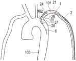
图3是示出将导管从左桡动脉插入,并将基端侧弯曲部抵接于左锁骨下动脉,将前端侧弯曲部配置在主动脉内且前端直线部及前端开口部朝向下行大动脉的状态的概略图。Fig. 3 is a diagram showing that the catheter is inserted from the left radial artery, the base-end curved part is abutted against the left subclavian artery, the distal-side curved part is arranged in the aorta, and the front-end straight part and the front-end opening part face the descending aorta An overview of the state.
图4是示出将导管插入髂总动脉及髂内动脉的状态的概略图。Fig. 4 is a schematic diagram showing a state in which a catheter is inserted into the common iliac artery and the internal iliac artery.
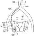
图5示出将导管卡合于子宫动脉的状态的概略图。Fig. 5 is a schematic diagram showing a state in which the catheter is engaged with the uterine artery.
图6是示出将导管卡合于子宫动脉的状态的其他例子的概略图。Fig. 6 is a schematic diagram showing another example of a state in which the catheter is engaged with the uterine artery.
图7是示出将导管卡合于前列腺动脉的状态的概略图。Fig. 7 is a schematic diagram showing a state in which the catheter is engaged with the prostatic artery.
具体实施方式Detailed ways
以下,参照附图说明本发明的实施方式。需要说明的是,为便于说明,附图的尺寸存在夸张而与实际尺寸不同的情况。另外,在本说明书及附图中,对实质上具有相同功能的构成要素标注相同的附图标记以省略重复说明。在本说明书中,将插入血管一侧称为“前端侧”,将进行操作一侧称为“基端侧”。Hereinafter, embodiments of the present invention will be described with reference to the drawings. It should be noted that, for convenience of description, the dimensions in the drawings may be exaggerated and may be different from actual dimensions. In addition, in this specification and drawings, the same code|symbol is attached|subjected to the component which has substantially the same function, and repeated description is abbreviate|omitted. In this specification, the side where the blood vessel is inserted is referred to as the "distal side", and the side where the operation is performed is referred to as the "basal side".
本实施方式的导管1如图1及图6所示,是用于与子宫动脉106或前列腺动脉107卡合的导管。导管1从患者的手臂的桡动脉100插入血管内,并卡合于子宫动脉106或前列腺动脉107。导管1也可以是所谓的引导管、血管造影导管、导丝支承导管或微导管。另外,导管1也可以是引导管与插入于引导管的内管且比引导管长的微导管的组合。The
如图1所示,导管1具有管状体2、配置在管状体2的基端侧毂部3、和抗扭保护部4。As shown in FIG. 1 , the
如图1、2所示,管状体2为长条并具有挠性。管状体2在其大致中心部形成有从基端延伸至前端的管腔21。As shown in Figures 1 and 2, the
毂部3形成有与管腔21连通的通路。毂部3例如能用于将导丝6、治疗用导管5(参照图5)等插入或拔出。另外,毂部3能用于注入X射线造影剂、药剂、生理盐水等各种液体。The hub 3 is formed with a passage communicating with the
抗扭保护部4由弹性材料形成。抗扭保护部4覆盖管状体2与毂部3连结的部分。由此,抗扭保护部4防止该部分附近的管状体2的弯折、扭折。The anti-twist protection 4 is formed from an elastic material. The anti-twist protection part 4 covers the part where the
接下来,对管状体2进行详细说明。管状体2具有大致直线状的主体部23和赋予为弯曲状态的形状的形状部24。形状部24的轴心位于同一平面X,形状部24实质上在同一平面X上弯曲。轴心是指通过该管状体2的中心的线,若管状体2为同心圆,则是指中心轴。形状部24具有基端侧弯曲部25、中间直线部26、前端侧弯曲部27及前端侧直线部28。基端侧弯曲部25从主体部23的前端向前端方向延伸,并且在平面X内弯曲。中间直线部26从基端侧弯曲部25的前端朝向前端方向以直线状延伸。前端侧弯曲部27从中间直线部26的前端朝向前端方向延伸,并且在平面X内与基端侧弯曲部25朝向相同方向弯曲。前端侧直线部28从前端侧弯曲部27的前端朝向前端方向以直线状延伸。需要说明的是,所谓实质上在同一平面X内弯曲,是指除了在同一平面X内弯曲以外,也可以还包含导管1的前端部以实用上能够发挥相同效果的程度而稍微从平面X突出情况。Next, the
将通过主体部23的轴心的直线设为第1轴A。将通过中间直线部26的轴心的直线设为第2轴B。将通过前端侧直线部28的轴心的直线设为第3轴C。Let a straight line passing through the axis of the
将第2轴B相对于第1轴A在前端侧形成的角度定义为第1角θ1。第1角θ1是基端侧弯曲部25中的管状体2的轴心的方向的变化量。即,基端侧弯曲部25规定第1角θ1。在第1角θ1为0°时,第2轴B与第1轴A一致,在第1角θ1为180°时,第2轴B相对于第1轴A向反方向折返。基端侧弯曲部25的轴心的曲率半径既可以在整个基端侧弯曲部25中恒定,也可以根据部位而变化。在基端侧弯曲部25中,轴心的曲率半径最小的部位(最急剧弯曲的部位)的第1最小曲率半径R1没有特别限定,优选为15mm~50mm,最优选为25mm。第1角θ1没有特别限定,优选为15°~70°,最优选为55°。The angle formed by the second axis B with respect to the first axis A on the front end side is defined as a first angle θ1. The first angle θ1 is the amount of change in the direction of the axis of the
将第3轴C相对于第2轴B在前端侧形成的角度定义为第2角θ2。第2角θ2是前端侧弯曲部27中的管状体2的轴心的方向的变化量。即,前端侧弯曲部27规定第2角θ2。在第2角θ2为0°时,第3轴C与第2轴B一致,在第2角θ2为180°时,第3轴C相对于第2轴B向反方向折返。前端侧弯曲部27的轴心的曲率半径既可以在整个前端侧弯曲部27中恒定,也可以根据部位而变化。在前端侧弯曲部27中,轴心的曲率半径最小的部位(最急剧弯曲的部位)的第2最小曲率半径R2没有特别限定,优选为1mm~10mm,最优选为5mm。第2最小曲率半径R2比第1最小曲率半径R1小。第1最小曲率半径R1优选为第2最小曲率半径R2的3倍以上11倍以下,最优选为5倍。第2角θ2没有特别限定,优选为30°~70°,最优选为50°。The angle formed by the third axis C with respect to the second axis B on the front end side is defined as a second angle θ2. The second angle θ2 is the amount of change in the direction of the axis of the
基端侧弯曲部25的沿着轴心的长度L1没有特别限定,例如为1mm~100mm。作为一例,基端侧弯曲部25的沿着轴心的长度L1为24mm。The length L1 along the axis of the base end side curved
中间直线部26的沿着轴心的长度L2没有特别限定,优选为1mm~100mm,最优选为16mm。The length L2 along the axis of the intermediate
前端侧弯曲部27的沿着轴心的长度L3没有特别限定,优选为1mm~10mm,最优选为4mm。The length L3 along the axis of the distal end side curved
前端侧直线部28的长度L4没有特别限定,优选为0.5mm~50mm,最优选为3mm。The length L4 of the front end side
管状体2也可以在从基端起向着前端方向到达规定位置的范围内埋设未图示的加强体。加强体是将多条线材编织成管状而形成的。加强体的最前端的位置没有特别限定,可配置于形状部24或主体部23。在比埋设有加强体的加强部更靠前端侧,具有未设置加强体的柔软部。优选柔软部的长度为500mm以下,更加优选为10~300mm。作为一例,在4Fr导管1的情况下,柔软部的长度为150mm。在5Fr导管1的情况下,柔软部的长度为150mm。A reinforcing body (not shown) may be embedded in the
导管1也可以从前端开口部22沿着轴心朝向基端方向被覆润滑性涂层。润滑性涂层也可以涂布于全长,例如,从前端开口部22沿着轴心朝向基端方向至少被覆500mm以下、更加优选为400mm以下的范围。因此,施术者也能够将导管1深插入子宫动脉106。润滑性涂层的构成材料例如能够举出含有丙烯酸缩水甘油酯、甲基丙烯酸缩水甘油酯、3,4-环氧环己基甲酯、甲基丙烯酸-3,4-环氧环己基甲酯、甲基丙烯酸β-甲基缩水甘油酯、烯丙基缩水甘油醚等环氧基的单体与N-甲基丙烯酰胺、N,N-二甲基丙烯酰胺、丙烯酰胺等亲水性单体的共聚物;由上述亲水性单体构成的(共)聚合物;羟丙基纤维素、羧甲基纤维素等纤维素系高分子物质;多糖类、聚乙烯醇、甲基乙烯基醚-马来酸酐共聚物、水溶性聚酰胺、聚((甲基)丙烯酸2-羟基乙酯)、聚乙二醇、聚丙烯酰胺、聚乙烯吡咯烷酮等。The
管状体2的外径优选为1mm(3Fr)~2.5mm(6Fr),更加优选为1.3mm(4Fr)~1.8mm(5Fr)。管状体2的有效长度优选为1300mm~1600mm。优选管状体2的尺寸能够根据患者、待导入的血管等适当选择。例如,在导管1从体型小的女性的通常的桡动脉100导入的情况下,优选管状体2的有效长度较短。在导管1从体型大的男性的远端桡动脉导入的情况下,优选管状体2的有效长度较长。有效长度是能够向血管、护套等内插入的部位的长度。在本实施方式中,有效长度是从抗扭保护部4的最前端到管状体2的最前端的长度,在本实施例中,子宫动脉用的导管1的有效长度是1350mm,前列腺动脉用的导管1的有效长度是1500mm,润滑性涂层的长度均为从前端起400mm。The outer diameter of the
管状体2也可以在前端部配置有比基端侧柔软的前端尖端。前端尖端由橡胶材料等富有柔软性的材料构成。The
构成管状体2的层数、各层的构成材料、加强体有无等也可以根据管状体2的长度方向的位置而不同。The number of layers constituting the
管状体2的构成材料例如能够使用苯乙烯系、聚烯烃系、聚氨酯系、聚酯系、聚酰胺系、聚丁二烯系、反式聚异戊二烯系、氟橡胶系、氯化聚乙烯系等各种热塑性弹性体、聚醚酮、聚酰亚胺系等,能够使用将其中的1种或2种以上组合而成的物质(聚合物合金、聚合物共混物、层叠体等)。也可以在管状体2的内周面配置低摩擦材料,以便容易将导丝6、其他导管等插入于管腔21内。低摩擦材料例如是聚四氟乙烯(PTFE)等氟系树脂材料。管状体2也可以包含X射线造影性的材料。The constituent materials of the
接下来,说明本实施方式的导管1的使用方法。Next, a method of using the
如图1所示,导管1从桡动脉100向血管内插入,穿过肱动脉及锁骨下动脉101插入下行大动脉103。导管1进一步通过髂总动脉104的主动脉髂动脉分支部104A而插入到髂总动脉104后,穿过髂内动脉105,与比髂内动脉105更靠末梢的血管卡合(engage)。导入导管1的桡动脉100是例如远端桡动脉(Distal radial Artery)、通常的桡动脉(ConventionalRadial Artery)、鼻烟窝-桡动脉(Snuff Box Radial Artery)等。在此,以患者是女性、将导管1插入于左臂的动脉来治疗子宫110的子宫肌瘤111的情况为例来进行说明。需要说明的是,导管1也可以从右臂的桡动脉100插入。As shown in FIG. 1 , a
在手术中,施术者将导丝6插入桡动脉100。接下来,施术者将管腔21中收容有导丝6的导管1沿着导丝6推进。通常,导丝6的前端与导管1的前端相比在前。因此,导管1的形状部24通过管腔21内的导丝6而变形为比被赋予形状的初始形状更接近直线的形状。形状部24的比初始形状更接近直线的形状而不限于直线形状,可以弯曲。During the operation, the operator inserts the
如图3所示,导丝6及导管1穿过锁骨下动脉101向主动脉弓102前进。在锁骨下动脉101与主动脉弓102相连的部位,导管1为了朝向下行大动脉103而必须大幅弯折。为了应对这一点,例如,施术者能够暂时使导丝6后退,将导丝6收容在导管1的管腔21中。导管1的未插入导丝6的部位的形状不受导丝6限制。因此,形状部24的未插入导丝6的部位欲要恢复为原本的弯曲形状。若导丝6与形状部24相比向基端侧后退,则形状部24整体恢复为原本的弯曲形状。需要说明的是,导丝6的前端也可以位于形状部24的内部。在该状态下,前端侧弯曲部27以比基端侧弯曲部25小的曲率半径而向与基端侧弯曲部25相同的那侧急剧地弯曲。此外,由于本发明中的形状部24比冠动脉治疗用导管的形状部小,因此导管1的最前端容易朝向于下行大动脉103而非上行大动脉。施术者能够利用形状部24的弯曲使导管1的前端从主动脉弓102朝向下行大动脉103前进。之后,施术者使导丝6从导管1向前端侧突出。由此,导丝6能够容易向下行大动脉103前进。接下来,施术者沿着导丝6推进导管1。由此,导管1能够容易地从主动脉弓102向下行大动脉103前进。导管1在下行大动脉103中向末梢侧(靠近下肢一侧)移动,到达主动脉髂动脉分支部104A的附近。需要说明的是,施术者也可以不使导丝6从导管1向前端侧突出,而使导管1在下行大动脉103中向末梢侧移动。As shown in FIG. 3 , the
在导管1到达主动脉髂动脉分支部104A的附近后,施术者根据需要使导丝6后退,将导丝6收容于导管1的管腔21。由此,形状部24的未插入导丝6的部位恢复为原本的弯曲形状。施术者能够利用形状部24的弯曲使导管1的前端通过主动脉髂动脉分支部104A而朝向右侧或左侧的髂总动脉,容易选择并插入所期望的那侧的髂总动脉104。After the
之后,施术者使导丝6成为从导管1向前端侧突出的状态。由此,如图4所示,导管1能够容易地在髂总动脉104中前进。需要说明的是,施术者也可以不使导丝6从导管1向前端侧突出,而使导管1在髂总动脉104中向末梢侧移动。导管1在髂总动脉104中向末梢侧移动,到达髂内动脉105的入口附近。Thereafter, the operator makes the
导丝6及导管1在到达髂内动脉105的入口附近后,施术者根据需要使导丝6后退,将导丝6收容在导管1的管腔21中。由此,形状部24的未插入导丝6的部位欲要恢复为原本的弯曲形状。在该状态下,前端侧弯曲部27以比基端侧弯曲部25小的曲率半径而向与基端侧弯曲部25相同的那侧急剧地弯曲。因此,导管1的最前端容易朝向于从髂总动脉104分支的髂内动脉105。施术者能够利用形状部24的弯曲使导管1的前端朝向髂内动脉105的入口,并能够不损伤具有比髂总动脉104小的内径的髂内动脉105而容易地插入。After the
之后,施术者使导丝6成为从导管1向前端侧突出的状态。由此,导管1能够容易地在髂内动脉105中前进。需要说明的是,施术者也可以不使导丝6从导管1向前端侧突出,而使导管1在髂内动脉105中向末梢侧移动。导管1在髂内动脉105中向末梢侧移动,到达子宫动脉106的入口附近。Thereafter, the operator makes the
在导丝6及导管1到达子宫动脉106的入口附近后,施术者根据需要使导丝6后退,将导丝6收容在导管1的管腔21中。由此,如图5所示,形状部24的未插入导丝6的部位欲要恢复为原本的弯曲形状。施术者能够利用形状部24的弯曲而使导管1的前端朝向子宫动脉106的入口,并容易地插入子宫动脉106。在该状态下,前端侧弯曲部27以比基端侧弯曲部25小的曲率半径向与基端侧弯曲部25相同的那侧急剧地弯曲。因此,导管1的最前端容易朝向从髂内动脉105分支且比髂内动脉105细的子宫动脉106。因此,导管1的前端侧弯曲部27和/或前端侧直线部28与子宫动脉106的血管壁接触,基端侧弯曲部25与髂内动脉105的血管壁中的、与子宫动脉106的入口部相反那一侧的血管壁接触并稳定地保持。由此,导管1的前端侧弯曲部27和/或前端侧直线部28能够良好地与子宫动脉106卡合而容易地维持位置。前端侧弯曲部27和/或前端侧直线部28可以与子宫动脉106的血管壁接触,也可以不接触。After the
之后,将比导管1长的治疗用导管5从毂部3插入导管1的管腔21。施术者能够使治疗用导管5从导管1的前端突出而容易插入子宫动脉106。之后,施术者能够经由治疗用导管5将用于封堵子宫110中的子宫肌瘤111的栓塞剂和/或药剂释放。导管1缓和因将栓塞剂、药剂等从治疗用导管5释放而产生的反作用。此外,导管1能够对治疗用导管5赋予支承力,以将治疗用导管5保持在希望的位置。因此,利用在将微导管等治疗用导管5插入导管1的管腔21时、或者释放栓塞剂、药剂等时的反作用,能够防止导管1的前端从子宫动脉106的入口拔出。需要说明的是,插入导管1的医疗设备也可以不是治疗用导管5。施术者也可以不从治疗用导管5而从导管1释放栓塞剂和/或药剂。Thereafter, the
或者,如图6所示,在髂内动脉105短的情况下,施术者能够利用形状部24的弯曲使导管1的前端朝向子宫动脉106的入口,使前端侧弯曲部27与髂内动脉105抵接,并使基端侧弯曲部25与髂总动脉104抵接。利用在该状态下将微导管等的治疗用导管5插入导管1的管腔21时、或释放栓塞剂、药剂等时的反作用,能够防止导管1的前端从子宫动脉106的入口拔出。Or, as shown in FIG. 6, when the internal
或者,也可以将前端弯曲部27卡合于子宫动脉上行枝,并将栓塞剂朝向末梢的动脉注入,施术者既可以使用导管1和治疗用导管5,也可以单独使用导管1释放栓塞剂和/或药剂。Alternatively, the front
需要说明的是,导管1也可以用于男性患者的前列腺120的前列腺肥大症的治疗。在该情况下,直至将导管1向髂内动脉105插入为止的导管1的操作与子宫肌瘤111治疗中的导管1的操作相同。导丝6及导管1穿过髂内动脉105到达前列腺动脉107的入口附近。前列腺动脉107是营养前列腺120的动脉,可以是例如下膀胱动脉、中直动脉、阴部内动脉、或闭孔动脉。在导丝6及导管1到达前列腺动脉107的入口附近后,施术者根据使需要导丝6后退而将导丝6收容在导管1的管腔21中。由此,如图7所示,形状部24的未插入导丝6的部位欲要恢复为原本的弯曲形状。施术者能够利用形状部24的弯曲使导管1的前端朝向前列腺动脉107的入口而容易向前列腺动脉107插入。在该状态下,前端侧弯曲部27向与基端侧弯曲部25相同的那侧弯曲。因此,导管1的最前端容易朝向从髂内动脉105分支且比髂内动脉105细的前列腺动脉107。因此,导管1的前端侧弯曲部27和/或前端侧直线部28与前列腺动脉107的血管壁接触,基端侧弯曲部25与髂内动脉105的血管壁中的、与前列腺动脉107的入口部相反那一侧的血管壁接触并稳定地保持。由此,导管1的前端侧弯曲部27和/或前端侧直线部28能够良好地卡合于前列腺动脉107,并容易地维持位置。It should be noted that the
之后,将比导管1长的治疗用导管5从毂部3插入导管1的管腔21中。施术者能够使治疗用导管5从导管1的前端突出,并容易地向前列腺动脉107插入。之后,施术者能够经由治疗用导管5来释放减少向前列腺的血流的栓塞剂和/或药剂。根据本实施方式的导管1,利用在将微导管等治疗用导管5插入导管1的管腔21时、或释放栓塞剂、药剂等时的反作用,能够防止导管1的前端从前列腺动脉107的入口拔出。需要说明的是,在髂内动脉105短的情况下,施术者能够利用形状部24的弯曲使导管1的前端朝向前列腺动脉107的入口,使前端侧弯曲部27与髂内动脉105抵接,并使基端侧弯曲部25与髂总动脉104抵接。需要说明的是,插入导管1的医疗设备也可以不是治疗用导管5。施术者也可以不从治疗用导管5而从导管1释放栓塞剂和/或药剂。Thereafter, the
如上所述,本实施方式的导管1是具有从基端连通至前端的管状体的子宫动脉卡合用的导管1,管状体2在前端部具有在实质相同的平面X上弯曲而被赋予形状的形状部24,形状部24具有:基端侧弯曲部25,其以规定第1角θ1的方式弯折;前端侧弯曲部27,其在比基端侧弯曲部25更靠前端侧之处规定第2角θ2,并向与基端侧弯曲部25相同的那侧弯折;直线状的中间直线部26,其配置在基端侧弯曲部25与前端侧弯曲部27之间;以及直线状的前端侧直线部28,其配置在比前端侧弯曲部27更靠前端侧,基端侧弯曲部25中的轴心的最小曲率半径即第1最小曲率半径R1为前端侧弯曲部27中的轴心的最小曲率半径即第2最小曲率半径R2的3倍以上11倍以下。As described above, the
就按照上述方式构成的导管1而言,使基端侧弯曲部25与髂内动脉105接触,关于以比基端侧弯曲部25小的曲率半径向与基端侧弯曲部25相同的方向急剧弯折的前端侧弯曲部27和/或较之前端侧弯曲部27的前端侧直线部28,使其朝向子宫动脉106而与子宫动脉106容易卡合。因此,导管1容易从桡动脉100到达子宫动脉106并与子宫动脉106卡合。In the
另外,本实施方式的导管1是具有从基端连通至前端的管状体2的前列腺动脉卡合用的导管1,管状体2在前端部具有在实质相同的平面X上弯曲而被赋予形状的形状部24,形状部24具有:基端侧弯曲部25,其以规定第1角θ1的方式弯折;前端侧弯曲部27,其在比基端侧弯曲部25更靠前端侧之处规定第2角θ2,并向与基端侧弯曲部25相同的那侧弯折;直线状的中间直线部26,其配置在基端侧弯曲部25与前端侧弯曲部27之间;以及直线状的前端侧直线部28,其配置在比前端侧弯曲部27更靠前端侧,基端侧弯曲部25中的轴心的最小曲率半径即第1最小曲率半径R1也可以是前端侧弯曲部27中的轴心的最小曲率半径即第2最小曲率半径R2的3倍以上11倍以下。In addition, the
就按照上述方式构成的导管1而言,使基端侧弯曲部25与髂内动脉105接触,关于以比基端侧弯曲部25小的曲率半径朝向与基端侧弯曲部25相同的方向急剧地弯折的前端侧弯曲部27和/或较之前端侧弯曲部27的前端侧直线部28,使其朝向前列腺动脉107而与前列腺动脉107容易卡合。因此,导管1容易从桡动脉到达前列腺动脉107并与前列腺动脉107卡合。In the
另外,也可以是,第1最小曲率半径R1为25mm,第2最小曲率半径R2为5mm,基端侧弯曲部25中的轴心的最小曲率半径即第1最小曲率半径R1为前端侧弯曲部中的轴心的最小曲率半径即第2最小曲率半径R2的5倍,中间直线部26的沿着轴心的长度是16mm,前端侧直线部28的沿着轴心的长度为3mm。由此,导管1容易到达桡动脉100子宫动脉106、前列腺动脉107并卡合。In addition, the first minimum radius of curvature R1 may be 25 mm, the second minimum radius of curvature R2 may be 5 mm, and the first minimum radius of curvature R1, which is the minimum radius of curvature of the axis in the base-end
另外,本发明也提供使用具有从基端连通至前端的管状体2的导管1的治疗方法。在本治疗方法中,管状体2在前端部具有在实质相同的平面X上弯曲而赋予形状的形状部24,形状部24具有:基端侧弯曲部25,其以规定第1角θ1的方式弯折;前端侧弯曲部27,其在比基端侧弯曲部25更靠前端侧之处规定第2角θ2,并向与基端侧弯曲部25相同的那侧弯折;直线状的中间直线部26,其配置在基端侧弯曲部25与前端侧弯曲部27之间;以及直线状的前端侧直线部28,其配置在比前端侧弯曲部27更靠前端侧,将基端侧弯曲部25的最小曲率半径R1为前端侧弯曲部27的最小曲率半径R2的3倍以上11倍以下的导管1从桡动脉插入血管内,将形状部24卡合于比髂内动脉105更靠末梢的血管。In addition, the present invention also provides a treatment method using the
就按照上述方式构成的治疗方法而言,使基端侧弯曲部25与髂内动脉105接触而稳定地保持于血管壁,关于以比基端侧弯曲部25小的曲率半径向与基端侧弯曲部25相同的方向急剧弯折的前端侧弯曲部27和/或较之前端侧弯曲部27的前端侧直线部28,使其朝向比髂内动脉105更靠末梢的血管并容易卡合。因此,施术者使导管1从桡动脉100到达比髂内动脉105更靠末梢的血管并与之卡合,以容易良好地进行治疗。In the treatment method configured as described above, the proximal
另外,在前述治疗方法中,插入导管1的桡动脉100也可以是远端桡动脉。由此,对于施术者而言,与通常的将导管1从桡动脉插入的情况相比以低侵害的方式,使导管1到达比髂内动脉105更靠末梢的血管并卡合而良好地进行治疗变得容易。In addition, in the aforementioned treatment method, the
另外,配置在比髂内动脉105更靠末梢且能够与形状部24卡合的血管也可以是子宫动脉106。由此,施术者能够利用从桡动脉100插入血管内的导管1而良好地进行子宫110的治疗。In addition, the
治疗对象也可以是子宫肌瘤111。由此,施术者能够利用从桡动脉100插入血管内的导管1而良好地进行子宫肌瘤111的治疗。The object of treatment may also be
另外,配置在比髂内动脉105更靠末梢且能够与形状部24卡合的血管也可以是前列腺动脉107。由此,施术者能够利用从桡动脉100插入血管内的导管1而良好进行前列腺120的治疗(例如,前列腺肥大症的治疗)。In addition, the
治疗对象也可以是由前列腺肥大症引起肥大的前列腺120。由此,施术者能够利用从桡动脉100插入血管内的导管1而良好地进行前列腺肥大症的治疗。The subject of treatment may also be an
需要说明的是,本发明并非仅限定于上述实施方式,而能够由本领域技术人员在本发明的技术思想内进行多种变更。It should be noted that the present invention is not limited to the above-mentioned embodiments, and various changes can be made within the technical idea of the present invention by those skilled in the art.
需要说明的是,本申请基于2020年6月1日提出的日本专利申请2020-95742号及2020年11月30日提出的日本专利申请2020-197870号,其公开内容被参照而整体包含在本申请中。It should be noted that this application is based on Japanese Patent Application No. 2020-95742 filed on June 1, 2020 and Japanese Patent Application No. 2020-197870 filed on November 30, 2020, the disclosures of which are incorporated herein by reference. Applying.
附图标记说明Explanation of reference signs
1 导管1 catheter
2 管状体2 tubular bodies
21 管腔21 lumen
23 主体部23 Main body
24 形状部24 Shape Department
25 基端侧弯曲部25 Bend at base end side
26 中间直线部26 Middle straight part
27 前端侧弯曲部27 Front side curved part
28 前端侧直线部28 Front side straight part
100 桡动脉100 Radial artery
101 锁骨下动脉101 Subclavian artery
102 主动脉弓102 Aortic arch
103 下行大动脉103 Descending aorta
104 髂总动脉104 Common iliac artery
105 髂内动脉105 Internal iliac artery
106 子宫动脉106 Uterine artery
107 前列腺动脉107 Prostatic artery
110 子宫110 Uterus
111 子宫肌瘤111 Uterine fibroids
120 前列腺120 Prostate
A 第1轴A 1st axis
B 第2轴B 2nd axis
C 第3轴C 3rd axis
R1 第1最小曲率半径R1 1st minimum radius of curvature
R2 第2最小曲率半径R2 The second minimum radius of curvature
X 平面X plane
θ1 第1角θ1 1st angle
θ2 第2角θ2 2nd angle
θ3 第3角θ3 3rd angle
Claims (10)
Translated fromChineseApplications Claiming Priority (5)
| Application Number | Priority Date | Filing Date | Title |
|---|---|---|---|
| JP2020095742 | 2020-06-01 | ||
| JP2020-095742 | 2020-06-01 | ||
| JP2020197870 | 2020-11-30 | ||
| JP2020-197870 | 2020-11-30 | ||
| PCT/JP2021/012976WO2021246030A1 (en) | 2020-06-01 | 2021-03-26 | Catheter and treatment method |
Publications (1)
| Publication Number | Publication Date |
|---|---|
| CN115666697Atrue CN115666697A (en) | 2023-01-31 |
Family
ID=78830802
Family Applications (1)
| Application Number | Title | Priority Date | Filing Date |
|---|---|---|---|
| CN202180035871.5APendingCN115666697A (en) | 2020-06-01 | 2021-03-26 | Catheters and Treatments |
Country Status (5)
| Country | Link |
|---|---|
| US (1) | US20230085830A1 (en) |
| EP (1) | EP4134119A4 (en) |
| JP (1) | JP7617103B2 (en) |
| CN (1) | CN115666697A (en) |
| WO (1) | WO2021246030A1 (en) |
Citations (3)
| Publication number | Priority date | Publication date | Assignee | Title |
|---|---|---|---|---|
| US20070112405A1 (en)* | 2005-11-15 | 2007-05-17 | Williams Terrell M | Delivery catheter |
| CN103566452A (en)* | 2012-07-20 | 2014-02-12 | 泰尔茂株式会社 | Coronary artery catheter and engaging method therefor |
| CN210542826U (en)* | 2019-05-09 | 2020-05-19 | 南京市妇幼保健院 | A dual-purpose catheter for unilateral puncture and bilateral internal iliac artery occlusion and uterine artery embolization |
Family Cites Families (11)
| Publication number | Priority date | Publication date | Assignee | Title |
|---|---|---|---|---|
| US5820592A (en)* | 1996-07-16 | 1998-10-13 | Hammerslag; Gary R. | Angiographic and/or guide catheter |
| JP3563540B2 (en)* | 1996-09-13 | 2004-09-08 | テルモ株式会社 | catheter |
| US6039723A (en)* | 1996-11-12 | 2000-03-21 | Junichi Tanaka | Catheter |
| US5916209A (en)* | 1997-12-24 | 1999-06-29 | Mick; Matthew J. | Coronary catheters for use in a transradial catheterization |
| US20060020246A1 (en)* | 2004-07-22 | 2006-01-26 | Mclucas Bruce | Angiographic catheter for uterine artery embolization |
| US7422581B2 (en) | 2005-09-02 | 2008-09-09 | Mclucas Bruce | Catheter with angled tip of reduced diameter |
| JP4737156B2 (en)* | 2007-07-18 | 2011-07-27 | ニプロ株式会社 | Guiding catheter |
| WO2014197962A1 (en)* | 2013-06-12 | 2014-12-18 | Carnevale Francisco Cesar | Catheter and methods related thereto |
| US10946170B2 (en)* | 2019-03-19 | 2021-03-16 | Terumo Kabushiki Kaisha | Catheter and method of engaging catheter |
| JP2020197870A (en) | 2019-05-31 | 2020-12-10 | キヤノン株式会社 | Information processing device, display control method, and program |
| JP6874186B2 (en) | 2020-03-04 | 2021-05-19 | 東芝テック株式会社 | Product registration device and its control program, as well as checkout system |
- 2021
- 2021-03-26JPJP2022528453Apatent/JP7617103B2/enactiveActive
- 2021-03-26CNCN202180035871.5Apatent/CN115666697A/enactivePending
- 2021-03-26WOPCT/JP2021/012976patent/WO2021246030A1/ennot_activeCeased
- 2021-03-26EPEP21818299.6Apatent/EP4134119A4/enactivePending
- 2022
- 2022-11-30USUS18/060,173patent/US20230085830A1/enactivePending
Patent Citations (3)
| Publication number | Priority date | Publication date | Assignee | Title |
|---|---|---|---|---|
| US20070112405A1 (en)* | 2005-11-15 | 2007-05-17 | Williams Terrell M | Delivery catheter |
| CN103566452A (en)* | 2012-07-20 | 2014-02-12 | 泰尔茂株式会社 | Coronary artery catheter and engaging method therefor |
| CN210542826U (en)* | 2019-05-09 | 2020-05-19 | 南京市妇幼保健院 | A dual-purpose catheter for unilateral puncture and bilateral internal iliac artery occlusion and uterine artery embolization |
Also Published As
| Publication number | Publication date |
|---|---|
| EP4134119A4 (en) | 2023-11-08 |
| JP7617103B2 (en) | 2025-01-17 |
| EP4134119A1 (en) | 2023-02-15 |
| WO2021246030A1 (en) | 2021-12-09 |
| JPWO2021246030A1 (en) | 2021-12-09 |
| US20230085830A1 (en) | 2023-03-23 |
Similar Documents
| Publication | Publication Date | Title |
|---|---|---|
| JP7543502B2 (en) | Methods and devices for transcarotid access | |
| US20220096104A1 (en) | Suction catheter systems for applying effective aspiration in remote vessels, especially cerebral arteries | |
| CN102395400B (en) | Medical guide wire | |
| CN113993570B (en) | Catheter tube | |
| US8142413B2 (en) | Coaxial guide catheter for interventional cardiology procedures | |
| US20190046764A1 (en) | Treatment Method Using Catheter Assembly and Catheter Assembly | |
| JP5300734B2 (en) | catheter | |
| CN113069193A (en) | Through radial artery access cerebrovascular intervention thimble assembly | |
| US11779729B2 (en) | Catheter and method of engaging catheter | |
| CN118542982A (en) | Extended suction catheter and catheter system having the same | |
| JP7651579B2 (en) | catheter | |
| US10052459B2 (en) | Catheter assembly and method | |
| CN221932814U (en) | Guiding catheter for bifurcated vessels | |
| WO2021044923A1 (en) | Catheter | |
| CN115666697A (en) | Catheters and Treatments | |
| CN116328164A (en) | Method and apparatus for sheath-less transradial catheterization | |
| CN222398655U (en) | Vascular sheath capable of changing interventional operation direction | |
| JP7442648B2 (en) | catheter | |
| JP2023116319A (en) | catheter | |
| WO2023175495A1 (en) | Catheter | |
| CN116940397A (en) | Guide extension catheter | |
| JPH07178181A (en) | Catheter introducer |
Legal Events
| Date | Code | Title | Description |
|---|---|---|---|
| PB01 | Publication | ||
| PB01 | Publication | ||
| SE01 | Entry into force of request for substantive examination | ||
| SE01 | Entry into force of request for substantive examination |