CN115652050A - Ultrasonic cavitation shot blasting device and method - Google Patents
Ultrasonic cavitation shot blasting device and methodDownload PDFInfo
- Publication number
- CN115652050A CN115652050ACN202211313009.9ACN202211313009ACN115652050ACN 115652050 ACN115652050 ACN 115652050ACN 202211313009 ACN202211313009 ACN 202211313009ACN 115652050 ACN115652050 ACN 115652050A
- Authority
- CN
- China
- Prior art keywords
- cavitation
- liquid
- ultrasonic cavitation
- ultrasonic
- frame
- Prior art date
- Legal status (The legal status is an assumption and is not a legal conclusion. Google has not performed a legal analysis and makes no representation as to the accuracy of the status listed.)
- Pending
Links
Images


Classifications
- Y—GENERAL TAGGING OF NEW TECHNOLOGICAL DEVELOPMENTS; GENERAL TAGGING OF CROSS-SECTIONAL TECHNOLOGIES SPANNING OVER SEVERAL SECTIONS OF THE IPC; TECHNICAL SUBJECTS COVERED BY FORMER USPC CROSS-REFERENCE ART COLLECTIONS [XRACs] AND DIGESTS
- Y02—TECHNOLOGIES OR APPLICATIONS FOR MITIGATION OR ADAPTATION AGAINST CLIMATE CHANGE
- Y02P—CLIMATE CHANGE MITIGATION TECHNOLOGIES IN THE PRODUCTION OR PROCESSING OF GOODS
- Y02P10/00—Technologies related to metal processing
- Y02P10/20—Recycling
Landscapes
- Structures Of Non-Positive Displacement Pumps (AREA)
Abstract
Description
Translated fromChinese技术领域technical field
本申请涉及机械加工技术领域,特别涉及一种超声空化喷丸装置及方法。The present application relates to the technical field of mechanical processing, in particular to an ultrasonic cavitation shot peening device and method.
背景技术Background technique
随着科技的发展,对材料性能的要求越来越高。喷丸成形工艺具有实用性好、适用范围广、价格低廉等特点,能够显著改善材料表面特性和疲劳性能,常被运用于工件表面的强化。但传统喷丸工艺也存在一定局限性,由于其弹丸能量较高而难以控制,且弹丸直径较大,因而不适用于一些特殊结构的强化,如:V型槽根部、孔的内表面以及航空发动机涡轮叶片叶尖等结构,因此研究一种针对特殊结构的喷丸强化工艺是势在必行的。With the development of science and technology, the requirements for material properties are getting higher and higher. The shot peening process has the characteristics of good practicability, wide application range, and low price. It can significantly improve the surface properties and fatigue properties of materials, and is often used to strengthen the surface of workpieces. However, the traditional shot peening process also has certain limitations. Due to the high energy of the projectile, it is difficult to control, and the diameter of the projectile is large, so it is not suitable for strengthening some special structures, such as: the root of the V-shaped groove, the inner surface of the hole and the aviation Engine turbine blade tips and other structures, so it is imperative to study a shot peening process for special structures.
空化现象又称气穴现象、空穴现象或空泡现象,是一种由于液体局部发生压降并且压力低至临界数值时,造成其中析出气体空泡或空穴的现象。完整的空化流程包含空泡的形成、发展和最后的溃灭,溃灭时伴随产生了高压冲击波、高速微射流及局部高温热点,其能量高度集中,可在工件表面局部区域产生极高的冲击压力,使其表面发生塑性变形。Cavitation phenomenon, also known as cavitation phenomenon, cavitation phenomenon or cavitation phenomenon, is a phenomenon in which gas bubbles or cavities are precipitated when the local pressure drop of the liquid occurs and the pressure is low to a critical value. The complete cavitation process includes the formation, development and final collapse of cavitation bubbles. The collapse is accompanied by high-pressure shock waves, high-speed micro-jet flow and local high-temperature hotspots. The energy is highly concentrated and can generate extremely high pressure in local areas on the workpiece surface. The impact pressure causes plastic deformation on the surface.
超声空化是以超声波为能量激励源,以液体为介质时激发的一种声空化现象。近年来,对超声空化的应用主要集中于超声清洗、超声医疗、声化学、均化、乳化以及超声诊断等领域,而对材料表面工艺强化领域应用却基本空白。由于超声空化产生的空化泡溃灭时常产生一定能量的冲击波,因此可将该能量用于传统喷丸无法强化的特殊结构。然而超声空化所产生的空化泡分散不具有普遍规律性,且声致空化泡生命周期短、溃灭速度快,无法达到能量集中利用的效果,使得空化泡溃灭能量利用率变低,因而需要提供一种提高空化泡溃灭能量利用率的超声空化喷丸装置及方法。Ultrasonic cavitation is an acoustic cavitation phenomenon that is excited when ultrasonic waves are used as the energy excitation source and liquid is used as the medium. In recent years, the application of ultrasonic cavitation is mainly concentrated in the fields of ultrasonic cleaning, ultrasonic medical treatment, sonochemistry, homogenization, emulsification, and ultrasonic diagnosis, while the application in the field of material surface process strengthening is basically blank. Since the collapse of cavitation bubbles produced by ultrasonic cavitation often produces shock waves with a certain energy, this energy can be used for special structures that cannot be strengthened by traditional shot peening. However, the dispersion of cavitation bubbles produced by ultrasonic cavitation does not have universal regularity, and the life cycle of acoustic cavitation bubbles is short and the collapse speed is fast, which cannot achieve the effect of concentrated energy utilization, which makes the energy utilization rate of cavitation bubble collapse lower. Low, so it is necessary to provide an ultrasonic cavitation shot peening device and method that can improve the energy utilization rate of cavitation bubble collapse.
发明内容Contents of the invention
本申请实施例提供了一种超声空化喷丸装置及方法,用以解决现有技术中超声空化产生的空化泡能量利用率低的问题。The embodiment of the present application provides an ultrasonic cavitation shot peening device and method to solve the problem of low energy utilization rate of cavitation bubbles generated by ultrasonic cavitation in the prior art.
一方面,本申请实施例提供了一种超声空化喷丸装置,包括:On the one hand, the embodiment of the present application provides an ultrasonic cavitation shot peening device, including:
框架;frame;
空化箱,内部存放有液体,空化箱设置在框架上;A cavitation box, which stores liquid inside, and the cavitation box is arranged on the frame;
升降机构,设置在框架上,且升降机构位于空化箱上方;The lifting mechanism is arranged on the frame, and the lifting mechanism is located above the cavitation box;
超声空化发生组件,与升降机构连接,且超声空化发生组件插入液体中,超声空化发生组件用于产生超声波,使液体中产生空化泡;The ultrasonic cavitation generating component is connected with the lifting mechanism, and the ultrasonic cavitation generating component is inserted into the liquid, and the ultrasonic cavitation generating component is used to generate ultrasonic waves to generate cavitation bubbles in the liquid;
托盘,设置在空化箱内部,且托盘浸没在液体中;a tray arranged inside the cavitation tank, and the tray is immersed in the liquid;
超声空化喷丸聚焦组件,设置在空化箱上,超声空化喷丸聚焦组件用于搅动液体,使液体中产生漩涡,对液体中的空化泡进行聚集。The ultrasonic cavitation shot-peening focusing assembly is arranged on the cavitation box, and the ultrasonic cavitation shot-peening focusing assembly is used to stir the liquid, generate vortices in the liquid, and gather cavitation bubbles in the liquid.
另一方面,本申请实施例还提供了一种超声空化喷丸方法,包括:On the other hand, the embodiment of the present application also provides an ultrasonic cavitation shot peening method, including:
将托盘放置在空化箱的液体中;Place the tray in the liquid in the cavitation tank;
启动超声空化发生组件,使液体中产生空化泡;Start the ultrasonic cavitation generating component to generate cavitation bubbles in the liquid;
调节升降机构,改变超声空化发生组件在液体中的位置;Adjust the lifting mechanism to change the position of the ultrasonic cavitation generating component in the liquid;
启动超声空化喷丸聚焦组件,搅动液体,使液体中产生漩涡,对液体中的空化泡进行聚集。Start the ultrasonic cavitation peening focusing component to stir the liquid to generate vortexes in the liquid and gather the cavitation bubbles in the liquid.
本申请中的一种超声空化喷丸装置及方法,具有以下优点:An ultrasonic cavitation shot peening device and method in the present application has the following advantages:
1、实现了在液体中产生空化泡,并且将空化泡溃灭时伴随产生的能量作用于工件表面特殊区域,产生极高的冲击压力,使其表面发生塑性变形,晶粒细化产生有利于提高疲劳性能的残余应力。1. Realize the generation of cavitation bubbles in the liquid, and act on the special area of the workpiece surface with the energy generated when the cavitation bubbles collapse, resulting in extremely high impact pressure, causing plastic deformation on the surface and grain refinement It is beneficial to improve the residual stress of fatigue performance.
2、利用步进电机带动旋转圆盘波轮转动,进一步在空化箱中形成漩涡,将产生的分散的空化泡形成汇聚,通过调节超声空化发生装置与工件之间的距离,继而实现空化泡溃灭时能量利用率的调节可控化。2. Use the stepper motor to drive the rotation of the rotating disk wave wheel, further form a vortex in the cavitation box, and form a convergence of the dispersed cavitation bubbles. By adjusting the distance between the ultrasonic cavitation generating device and the workpiece, and then realize The regulation and controllability of energy utilization rate when cavitation bubble collapses.
3、与普通超声空化装置相比,本申请的装置可实现聚焦,节省了人力和时间的成本。3. Compared with ordinary ultrasonic cavitation devices, the device of the present application can achieve focusing, saving manpower and time costs.
附图说明Description of drawings
为了更清楚地说明本申请实施例或现有技术中的技术方案,下面将对实施例或现有技术描述中所需要使用的附图作简单地介绍,显而易见地,下面描述中的附图仅仅是本申请的一些实施例,对于本领域普通技术人员来讲,在不付出创造性劳动的前提下,还可以根据这些附图获得其他的附图。In order to more clearly illustrate the technical solutions in the embodiments of the present application or the prior art, the following will briefly introduce the drawings that need to be used in the description of the embodiments or the prior art. Obviously, the accompanying drawings in the following description are only These are some embodiments of the present application. Those skilled in the art can also obtain other drawings based on these drawings without creative work.
图1为本申请实施例提供的一种超声空化喷丸装置的主视图;Fig. 1 is the front view of a kind of ultrasonic cavitation shot peening device provided by the embodiment of the present application;
图2为本申请实施例提供的一种超声空化喷丸装置的侧视图;Fig. 2 is a side view of an ultrasonic cavitation shot peening device provided in an embodiment of the present application;
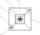
图3为本申请实施例提供的一种超声空化喷丸装置的俯视图;Fig. 3 is a top view of an ultrasonic cavitation shot peening device provided in an embodiment of the present application;
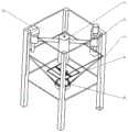
图4为本申请实施例提供的一种超声空化喷丸装置的轴侧图;Fig. 4 is an axonometric view of an ultrasonic cavitation shot peening device provided in an embodiment of the present application;
图5为本申请实施例提供的框架的结构示意图;FIG. 5 is a schematic structural diagram of a framework provided by an embodiment of the present application;
图6为本申请实施例提供的升降机构的结构示意图;Fig. 6 is a schematic structural diagram of the lifting mechanism provided by the embodiment of the present application;
图7为本申请实施例提供的超声空化发生组件和超声空化冷却组件的结构示意图;Fig. 7 is a schematic structural diagram of an ultrasonic cavitation generating component and an ultrasonic cavitation cooling component provided by an embodiment of the present application;
图8为本申请实施例提供的托盘的结构示意图;Fig. 8 is a schematic structural diagram of the pallet provided by the embodiment of the present application;
图9为本申请实施例提供的超声空化喷丸聚焦组件的结构示意图。FIG. 9 is a schematic structural diagram of an ultrasonic cavitation shot-peening focusing assembly provided in an embodiment of the present application.
附图标号说明:1-框架,2-升降机构,3-超声空化发生组件,4-超声空化冷却组件,5-托盘,6-超声空化喷丸聚焦组件,1-1-第一立柱,1-2-第一连接板,1-3-第一滑块挡板,1-4-第二连接板,1-5-第三连接板,1-6-第二滑块挡板,1-7-第四连接板,1-8-第二立柱,1-9-第三立柱,1-10-第四立柱,1-11-空化箱,1-12-第三滑块挡板,2-1-第一驱动单元,2-2-丝杆,2-3-第一滑块,2-4-第二滑块,2-5-导向杆,3-1-超声空化发生单元,3-2-固定杆,4-1-气体导管,4-2-空气压缩机,5-1-放置盘,5-2-工件,6-1-第一紧扣单元,6-2-转轴,6-3-旋转圆盘波轮,6-4-第二紧扣单元,6-5-第二驱动单元。Description of reference numerals: 1-frame, 2-lifting mechanism, 3-ultrasonic cavitation generating component, 4-ultrasonic cavitation cooling component, 5-tray, 6-ultrasonic cavitation shot peening focusing component, 1-1-first Column, 1-2-first connecting plate, 1-3-first slider baffle, 1-4-second connecting plate, 1-5-third connecting plate, 1-6-second slider baffle , 1-7-the fourth connecting plate, 1-8-the second column, 1-9-the third column, 1-10-the fourth column, 1-11-cavitation box, 1-12-the third slider Baffle, 2-1-first drive unit, 2-2-screw, 2-3-first slider, 2-4-second slider, 2-5-guide rod, 3-1-ultrasonic space Chemical generation unit, 3-2-fixed rod, 4-1-gas conduit, 4-2-air compressor, 5-1-placement plate, 5-2-workpiece, 6-1-first fastening unit, 6 -2-rotating shaft, 6-3-rotating disc impeller, 6-4-second fastening unit, 6-5-second driving unit.
具体实施方式Detailed ways
下面将结合本申请实施例中的附图,对本申请实施例中的技术方案进行清楚、完整地描述,显然,所描述的实施例仅仅是本申请一部分实施例,而不是全部的实施例。基于本申请中的实施例,本领域普通技术人员在没有做出创造性劳动前提下所获得的所有其他实施例,都属于本申请保护的范围。The following will clearly and completely describe the technical solutions in the embodiments of the application with reference to the drawings in the embodiments of the application. Apparently, the described embodiments are only some of the embodiments of the application, not all of them. Based on the embodiments in this application, all other embodiments obtained by persons of ordinary skill in the art without making creative efforts belong to the scope of protection of this application.
图1-9为本申请实施例提供的一种超声空化喷丸装置的结构示意图。本申请实施例提供了一种超声空化喷丸装置,包括:1-9 are structural schematic diagrams of an ultrasonic cavitation shot peening device provided in an embodiment of the present application. An embodiment of the present application provides an ultrasonic cavitation shot peening device, including:
框架1;
空化箱1-11,内部存放有液体,空化箱1-11设置在框架1上;The cavitation box 1-11 stores liquid inside, and the cavitation box 1-11 is arranged on the
升降机构2,设置在框架1上,且升降机构2位于空化箱1-11上方;The
超声空化发生组件3,与升降机构2连接,且超声空化发生组件3插入液体中,超声空化发生组件3用于产生超声波,使液体中产生空化泡;The ultrasonic cavitation generating
托盘5,设置在空化箱1-11内部,且托盘5浸没在液体中;The
超声空化喷丸聚焦组件6,设置在空化箱1-11上,超声空化喷丸聚焦组件6用于搅动液体,使液体中产生漩涡,对液体中的空化泡进行聚集。The ultrasonic cavitation shot-
示例性地,托盘5包括放置盘5-1和放置在放置盘5-1上的工件5-2,而且根据工件5-2的不同,可以定制不同的放置盘5-1。在本申请的实施例中,超声空化发生组件3正对放置盘5-1的中心,因此工件5-2优选放置在放置盘5-1的中心位置。Exemplarily, the
本申请提供的一种超声空化喷丸装置,启动超声空化发生组件3后在液体中可以产生空化泡,空化泡溃灭时伴随产生的能量能够作用于工件5-2表面的特殊区域,对工件5-2表面施加极高的冲击压力,使其表面发生塑性变形。同时,利用超声空化喷丸聚焦组件6在空化箱1-11中形成漩涡,将产生的分散的空化泡聚齐起来,通过调节升降机构改变超声空化发生组件3与工件5-2之间的距离,继而提高空化泡溃灭时能量的利用率,实现工件5-2表面强化处理程度可控化。An ultrasonic cavitation shot peening device provided by the present application can generate cavitation bubbles in the liquid after starting the ultrasonic
在一种可能的实施例中,框架1包括多个立柱和与立柱数量相同的连接板,多个立柱相互平行设置,连接板连接在相邻的两个立柱之间。In a possible embodiment, the
示例性地,本申请中的立柱和连接板的数量均为四个,四个立柱分别为第一立柱1-1、第二立柱1-8、第三立柱1-9和第四立柱1-10,四个连接板分别为第一连接板1-2、第二连接板1-4、第三连接板1-5和第四连接板1-7。Exemplarily, the number of uprights and connecting plates in this application is four, and the four uprights are respectively the first upright 1-1, the second upright 1-8, the third upright 1-9 and the fourth upright 1- 10. The four connecting plates are respectively the first connecting plate 1-2, the second connecting plate 1-4, the third connecting plate 1-5 and the fourth connecting plate 1-7.
其中,第一立柱1-1、第二立柱1-8、第三立柱1-9和第四立柱1-10均可采用铝合金型材制成,且四个立柱均竖直放置,形成立方体结构。第一连接板1-2、第二连接板1-4、第三连接板1-5和第四连接板1-7均可采用钢化玻璃板,且分别位于立方体结构的四面,四个连接板均竖直放置并与四个立柱相互粘接,四个立柱和四个连接板粘接在一起形成横截面为正方形的棱柱。Among them, the first column 1-1, the second column 1-8, the third column 1-9 and the fourth column 1-10 can be made of aluminum alloy profiles, and the four columns are placed vertically to form a cubic structure . The first connection plate 1-2, the second connection plate 1-4, the third connection plate 1-5 and the fourth connection plate 1-7 can all adopt toughened glass plates, and are respectively located on the four sides of the cube structure, and the four connection plates They are placed vertically and bonded to four uprights, and the four uprights and four connecting plates are bonded together to form a square prism with a cross section.
在一种可能的实施例中,升降机构2包括:丝杆2-2,转动设置在框架1上;第一驱动单元2-1,设置在框架1上,丝杆2-2的一端与第一驱动单元2-1的转动端连接;导向杆2-5固定设置在框架1上,且导向杆2-5和丝杆2-2平行;第一滑块2-3,螺接在丝杆2-2上;第二滑块2-4,滑动设置在导向杆2-5上;超声空化发生组件3连接在第一滑块2-3和第二滑块2-4之间。In a possible embodiment, the
示例性地,框架1上还设置有:第一滑块挡板1-3,第一驱动单元2-1的主体设置在第一滑块挡板1-3上;第二滑块挡板1-6,导向杆2-5固定设置在第二滑块挡板1-6上;第三滑块挡板1-12,与第一滑块挡板1-3正对,丝杆2-2的末端转动设置在第三滑块挡板1-12上。Exemplarily, the
第一驱动单元2-1可以采用步进电机,丝杆2-2竖直放置,其上端固定在第一驱动单元2-1的转动端,即转轴,丝杆2-2的下端通过轴承转动设置在第三滑块挡板1-12上。第一滑块2-3上设置有与丝杆2-2相配合的螺纹,使第一滑块2-3能够沿着丝杆2-2上下移动。导向杆2-5竖直放置,其上端可以通过轴承转动设置或固定设置在第二滑块挡板1-6上,下端悬空。第二滑块2-4上设置有导向槽,导向杆2-5穿过导向槽,使第二滑块2-4能够沿着导向杆2-5上下移动。第一驱动单元2-1转动时带动丝杆2-2旋转,使第一滑块2-3与第二滑块2-4之间相连接的超声空化发生组件3上下移动。为提高第一驱动单元2-1对超声空化发生组件3高度的调节精度,需要使丝杆2-2上螺纹的螺距较小,而且在调节过程中,超声空化发生组件3和工件5-2之间的距离最大为30mm。The first driving unit 2-1 can adopt a stepping motor, the screw mandrel 2-2 is placed vertically, and its upper end is fixed on the rotating end of the first driving unit 2-1, that is, the rotating shaft, and the lower end of the screw mandrel 2-2 rotates through a bearing Set on the third slider baffle plate 1-12. The first slider 2-3 is provided with a screw thread matched with the screw mandrel 2-2, so that the first slider 2-3 can move up and down along the screw mandrel 2-2. Guide bar 2-5 is placed vertically, and its upper end can be set on the second slider baffle plate 1-6 by bearing rotation or fixedly, and the lower end is suspended in the air. The second slider 2-4 is provided with a guide groove, and the guide rod 2-5 passes through the guide groove, so that the second slider 2-4 can move up and down along the guide rod 2-5. When the first driving unit 2-1 rotates, it drives the screw rod 2-2 to rotate, so that the ultrasonic
在本申请的实施例中,三个滑块挡板中的两个位于型材框架顶部,分别为第一滑块挡板1-3和第二滑块挡板1-6,第一滑块挡板1-3和第二滑块挡板1-6分别放置在框架1的对角侧,并与立柱和连接板固定连接。第三滑块挡板1-12位于第一滑块挡板1-3的正下方,且二者存在一定距离,第三滑块挡板1-12也固定连接于立柱和连接板。In the embodiment of the present application, two of the three slider baffles are located on the top of the profile frame, respectively the first slider baffle 1-3 and the second slider baffle 1-6, the first slider baffle The board 1-3 and the second slider baffle 1-6 are respectively placed on the diagonal sides of the
在一种可能的实施例中,超声空化发生组件3包括:超声空化发生单元3-1,插入液体中;固定杆3-2,第一滑块2-3和第二滑块2-4分别通过一个固定杆3-2与超声空化发生单元3-1连接。In a possible embodiment, the ultrasonic
示例性地,超声空化发生单元3-1为柱状结构,其下端为平整的圆形辐射面,该辐射面伸入存在液体的空化箱1-11,产生空化泡和空泡云。连接杆3-2连接第一滑块2-3和第二滑块2-4,且两个连接杆3-2均沿框架1的对角线水平放置。Exemplarily, the ultrasonic cavitation generating unit 3-1 is a columnar structure with a flat circular radiating surface at its lower end. The radiating surface extends into the cavitation tank 1-11 where liquid exists to generate cavitation bubbles and cavitation clouds. The connecting rod 3-2 connects the first sliding block 2-3 and the second sliding block 2-4, and both connecting rods 3-2 are placed horizontally along the diagonal of the
在一种可能的实施例中,超声空化喷丸聚焦组件6包括:旋转圆盘波轮6-3,位于空化箱1-11的内底部;第二驱动单元6-5,设置在空化箱1-11的外底部,旋转圆盘波轮6-3底部设置有转轴6-2,转轴6-2穿过空化箱1-11的底面并与第二驱动单元6-5的转动端连接。In a possible embodiment, the ultrasonic cavitation shot-
示例性地,空化箱1-11也可以采用四个箱板粘连而成,箱板则也可以采用钢化玻璃板,箱板的上端与一块连接板相连接,下端连接在一起后形成圆筒,且四个箱板连接在一起形成倒棱台结构的空化箱1-11。Exemplarily, the cavitation box 1-11 can also be formed by bonding four box plates, and the box plates can also be made of tempered glass plates, the upper ends of the box plates are connected with a connecting plate, and the lower ends are connected together to form a cylinder , and the four box plates are connected together to form a cavitation box 1-11 with chamfered terrace structure.
空化箱1-11底部的圆筒中可以设置与箱板同材质的底板,也可以设置与箱板为不同材质的密封圈,无论采用底板还是密封圈,转轴6-2穿过后均需要确保空化箱1-11中的液体不会泄露。The cylinder at the bottom of the cavitation box 1-11 can be provided with a bottom plate made of the same material as the box plate, or a sealing ring made of a different material from the box plate. No matter whether the bottom plate or the sealing ring is used, after the rotating shaft 6-2 passes through, it is necessary to ensure the air The fluid in tank 1-11 will not leak.
在一种可能的实施例中,转轴6-2位于空化箱1-11外部的一端连接有第一紧扣单元6-1,第二驱动单元6-5的转动端连接有第二紧扣单元6-4,第一紧扣单元6-1和第二紧扣单元6-4紧扣连接在一起。In a possible embodiment, one end of the rotating shaft 6-2 outside the cavitation box 1-11 is connected with a first fastening unit 6-1, and the rotating end of the second driving unit 6-5 is connected with a second fastening The unit 6-4, the first fastening unit 6-1 and the second fastening unit 6-4 are fastened together.
示例性地,第一紧扣装置6-1和第二紧扣装置6-4均可以具有凸起和凹陷结构,且第一紧扣装置6-1上的凸起需要和第二紧扣装置6-4上的凹陷匹配,第二驱动单元6-5也可以采用步进电机。转轴6-2的底端可以与第一紧扣装置6-1固定连接,第二紧扣装置6-4的上端与第一紧扣装置6-1紧扣连接在一起,下端固定在第二驱动单元6-5的转动端,即转轴上,通过第二驱动单元6-5可以带动旋转圆盘波轮6-3转动,使液体中的空化泡聚集在一起。Exemplarily, both the first fastening device 6-1 and the second fastening device 6-4 can have a protrusion and a concave structure, and the protrusion on the first fastening device 6-1 needs to be connected with the second fastening device. The depressions on the 6-4 match, and the second drive unit 6-5 can also adopt a stepper motor. The bottom end of the rotating shaft 6-2 can be fixedly connected with the first fastening device 6-1, the upper end of the second fastening device 6-4 is tightly connected with the first fastening device 6-1, and the lower end is fixed on the second fastening device 6-1. The rotating end of the driving unit 6-5, that is, the rotating shaft, can drive the rotating disc impeller 6-3 to rotate through the second driving unit 6-5, so that the cavitation bubbles in the liquid gather together.
在一种可能的实施例中,框架1上还设置有超声空化冷却组件4,超声空化冷却组件4包括:空气压缩机4-2;气体导管4-1,连接在超声空化发生组件3和空气压缩机4-2之间。In a possible embodiment, an ultrasonic
示例性地,空气压缩机4-2用于冷却超声空化发生单元3-1,防止过热烧坏超声空化发生单元3-1。Exemplarily, the air compressor 4-2 is used for cooling the ultrasonic cavitation generating unit 3-1, so as to prevent the ultrasonic cavitation generating unit 3-1 from being burned due to overheating.
本申请还提供了一种超声空化喷丸方法,该方法包括:The application also provides a method of ultrasonic cavitation shot peening, the method comprising:
将托盘5放置在空化箱1-11的液体中;Placing the
启动超声空化发生组件3,使液体中产生空化泡;Start the ultrasonic
调节升降机构2,改变超声空化发生组件3在液体中的位置;Adjust the
启动超声空化喷丸聚焦组件6,搅动液体,使液体中产生漩涡,对液体中的空化泡进行聚集。The ultrasonic cavitation shot-
尽管已描述了本申请的优选实施例,但本领域内的技术人员一旦得知了基本创造性概念,则可对这些实施例做出另外的变更和修改。所以,所附权利要求意欲解释为包括优选实施例以及落入本申请范围的所有变更和修改。While preferred embodiments of the present application have been described, additional changes and modifications to these embodiments can be made by those skilled in the art once the basic inventive concept is appreciated. Therefore, the appended claims are intended to be construed to cover the preferred embodiment and all changes and modifications which fall within the scope of the application.
显然,本领域的技术人员可以对本申请进行各种改动和变型而不脱离本申请的精神和范围。这样,倘若本申请的这些修改和变型属于本申请权利要求及其等同技术的范围之内,则本申请也意图包含这些改动和变型在内。Obviously, those skilled in the art can make various changes and modifications to the application without departing from the spirit and scope of the application. In this way, if these modifications and variations of the present application fall within the scope of the claims of the present application and their equivalent technologies, the present application is also intended to include these modifications and variations.
Claims (10)
Priority Applications (1)
| Application Number | Priority Date | Filing Date | Title |
|---|---|---|---|
| CN202211313009.9ACN115652050A (en) | 2022-10-25 | 2022-10-25 | Ultrasonic cavitation shot blasting device and method |
Applications Claiming Priority (1)
| Application Number | Priority Date | Filing Date | Title |
|---|---|---|---|
| CN202211313009.9ACN115652050A (en) | 2022-10-25 | 2022-10-25 | Ultrasonic cavitation shot blasting device and method |
Publications (1)
| Publication Number | Publication Date |
|---|---|
| CN115652050Atrue CN115652050A (en) | 2023-01-31 |
Family
ID=84990437
Family Applications (1)
| Application Number | Title | Priority Date | Filing Date |
|---|---|---|---|
| CN202211313009.9APendingCN115652050A (en) | 2022-10-25 | 2022-10-25 | Ultrasonic cavitation shot blasting device and method |
Country Status (1)
| Country | Link |
|---|---|
| CN (1) | CN115652050A (en) |
Cited By (1)
| Publication number | Priority date | Publication date | Assignee | Title |
|---|---|---|---|---|
| CN117140370A (en)* | 2023-10-27 | 2023-12-01 | 中北大学 | A six-degree-of-freedom dual-frequency ultrasonic cavitation shot peening device with a special fixture |
Citations (6)
| Publication number | Priority date | Publication date | Assignee | Title |
|---|---|---|---|---|
| US20160346758A1 (en)* | 2015-06-01 | 2016-12-01 | Cetamax Ventures Ltd. | Systems and methods for processing fluids |
| CN110864988A (en)* | 2019-10-23 | 2020-03-06 | 东北大学 | A device and method for studying the evolution of cavitation |
| CN111300273A (en)* | 2020-02-17 | 2020-06-19 | 中国石油大学(华东) | Texture processing test device based on controllable cavitation erosion technology |
| CN111843843A (en)* | 2020-06-16 | 2020-10-30 | 江苏大学 | A method for ultrasonic uniform cavitation shot peening of mixed particle solution |
| CN112192447A (en)* | 2020-09-10 | 2021-01-08 | 杭州电子科技大学 | Outfield ultrasonic auxiliary jet polishing tool head device |
| CN112680579A (en)* | 2020-12-10 | 2021-04-20 | 西北工业大学 | Ultrasonic shot peening strengthening device for round bar-shaped test piece |
- 2022
- 2022-10-25CNCN202211313009.9Apatent/CN115652050A/enactivePending
Patent Citations (6)
| Publication number | Priority date | Publication date | Assignee | Title |
|---|---|---|---|---|
| US20160346758A1 (en)* | 2015-06-01 | 2016-12-01 | Cetamax Ventures Ltd. | Systems and methods for processing fluids |
| CN110864988A (en)* | 2019-10-23 | 2020-03-06 | 东北大学 | A device and method for studying the evolution of cavitation |
| CN111300273A (en)* | 2020-02-17 | 2020-06-19 | 中国石油大学(华东) | Texture processing test device based on controllable cavitation erosion technology |
| CN111843843A (en)* | 2020-06-16 | 2020-10-30 | 江苏大学 | A method for ultrasonic uniform cavitation shot peening of mixed particle solution |
| CN112192447A (en)* | 2020-09-10 | 2021-01-08 | 杭州电子科技大学 | Outfield ultrasonic auxiliary jet polishing tool head device |
| CN112680579A (en)* | 2020-12-10 | 2021-04-20 | 西北工业大学 | Ultrasonic shot peening strengthening device for round bar-shaped test piece |
Cited By (2)
| Publication number | Priority date | Publication date | Assignee | Title |
|---|---|---|---|---|
| CN117140370A (en)* | 2023-10-27 | 2023-12-01 | 中北大学 | A six-degree-of-freedom dual-frequency ultrasonic cavitation shot peening device with a special fixture |
| CN117140370B (en)* | 2023-10-27 | 2024-01-02 | 中北大学 | Six-degree-of-freedom double-frequency ultrasonic cavitation shot blasting device with special fixture |
Similar Documents
| Publication | Publication Date | Title |
|---|---|---|
| US4468130A (en) | Mixing apparatus | |
| US9157324B2 (en) | Peripheral tunnels propeller | |
| US3416729A (en) | Liquid aerator | |
| CN115652050A (en) | Ultrasonic cavitation shot blasting device and method | |
| CN104786157B (en) | A kind of ultrasonic polishing processing unit (plant) using gas-liquid-solid three-phase abrasive Flow | |
| JPS588541A (en) | Agitator with approximately triangular radial blade inclining in circumferential direction | |
| JPS6351928A (en) | Impeller | |
| US11123840B2 (en) | Finishing a surface of a component made by additive manufacturing | |
| CA2477064C (en) | Dual direction mixing impeller and method | |
| CN108246143A (en) | A kind of percolation agitating paddle | |
| CN102169071B (en) | Rotating disk cavitation test bench based on flexible rotor | |
| CN104043382A (en) | Hydrodynamic cavitation generating device | |
| CN106621927A (en) | Adhesive stirrer capable of stirring stably and uniformly | |
| CN203990441U (en) | The mulser that a kind of bi-motor stirs | |
| Malzacher et al. | A low speed compressor test rig for flutter investigations | |
| JP2020514671A (en) | Method and device for heating and cleaning liquids | |
| CN206715839U (en) | A kind of agitating device based on the compound cavitation of multiple spot | |
| Antoniak et al. | Visualization research on the influence of an ultrasonic degassing system on the operation of a hydraulic gear pump | |
| CN210386209U (en) | A self-priming adjustable microbubble generator | |
| CN101446311A (en) | Passive pulse ejector for inhibiting blade back separation of air compressor | |
| US7677790B2 (en) | Fluid rotation system for a cavitation chamber | |
| CN110141984A (en) | A new type of car paint stirring paddle | |
| CN113828206B (en) | Jet-type jet stirring paddle for improving fluid mixing effect | |
| CN209735479U (en) | A mixing and stirring device for ceramic sol spraying liquid | |
| CN108787408B (en) | Low-frequency pulse vibration generator |
Legal Events
| Date | Code | Title | Description |
|---|---|---|---|
| PB01 | Publication | ||
| PB01 | Publication | ||
| SE01 | Entry into force of request for substantive examination | ||
| SE01 | Entry into force of request for substantive examination | ||
| RJ01 | Rejection of invention patent application after publication | Application publication date:20230131 | |
| RJ01 | Rejection of invention patent application after publication |