CN115645054A - A doctor-side surgical control device, control method and storage medium - Google Patents
A doctor-side surgical control device, control method and storage mediumDownload PDFInfo
- Publication number
- CN115645054A CN115645054ACN202211180460.8ACN202211180460ACN115645054ACN 115645054 ACN115645054 ACN 115645054ACN 202211180460 ACN202211180460 ACN 202211180460ACN 115645054 ACN115645054 ACN 115645054A
- Authority
- CN
- China
- Prior art keywords
- display device
- doctor
- connecting structure
- move
- force
- Prior art date
- Legal status (The legal status is an assumption and is not a legal conclusion. Google has not performed a legal analysis and makes no representation as to the accuracy of the status listed.)
- Pending
Links
Images


Landscapes
- User Interface Of Digital Computer (AREA)
Abstract
Description
Translated fromChinese技术领域technical field
本说明书实施例涉及医疗器械技术领域,特别涉及一种医生端手术控制设备、控制方法及存储介质。The embodiments of this specification relate to the technical field of medical devices, and in particular to a doctor-side surgical control device, control method and storage medium.
背景技术Background technique
凭借着伤害小、出血少、恢复快的优势,微创外科手术得到的迅猛的发展和广泛的应用。在微创外科手术中,内窥镜拍摄到的图像被图像平台转发至医生控制端,使得医生能够通过医生控制端实时查看手术中患者体内的状况,并操作手术器械执行手术操作。With the advantages of less injury, less bleeding, and faster recovery, minimally invasive surgery has been rapidly developed and widely used. In minimally invasive surgery, the images captured by the endoscope are forwarded to the doctor's control terminal by the image platform, so that the doctor can view the condition of the patient's body in real time through the doctor's control terminal, and operate the surgical instrument to perform the operation.
目前手术场景中具有较多的信息需要被展示,例如,医生在查看内窥镜拍摄到的患者体内图像的同时,还需要掌握患者身体状况数据、手术流程信息、术前影像资料信息等。将这些信息展示在同一显示器上可能会产生遮挡现象,切换查看内容也会提高手术过程的繁琐性,不利于手术的进行。此外,在手术过程中,可能不仅需要将图像信息等展示给医生,还需要展示给其他医护人员。综上,目前的手术场景对于手术图像的展示提出了较高的要求,当前亟需一种能够适应手术场景中复杂多变的图像展示需求的方案。At present, there is a lot of information to be displayed in the surgical scene. For example, while viewing the internal images of the patient captured by the endoscope, the doctor also needs to grasp the patient's physical condition data, surgical process information, and preoperative image information. Displaying these information on the same display may cause occlusion, and switching to view content will also increase the cumbersomeness of the surgical process, which is not conducive to the operation. In addition, during the operation, it may be necessary not only to display the image information to the doctor, but also to other medical staff. To sum up, the current surgical scene puts forward higher requirements for the display of surgical images, and there is an urgent need for a solution that can adapt to the complex and changeable image display requirements in the surgical scene.
发明内容Contents of the invention
本说明书实施例的目的是提供一种医生端手术控制设备、控制方法及存储介质,以解决如何适应手术场景中复杂多变的图像展示需求的问题。The purpose of the embodiments of this specification is to provide a doctor-side surgical control device, control method and storage medium to solve the problem of how to adapt to complex and changeable image display requirements in surgical scenarios.
为了解决上述技术问题,本说明书实施例提出了一种医生端手术控制设备,包括固定支架、第一连接结构、第二连接结构、第一显示装置、第二显示装置和驱动电机;所述第一显示装置通过第一连接结构与所述固定支架连接,所述第二显示装置通过第二连接结构与所述固定支架连接;所述第一连接结构和所述第二连接结构分别基于所述固定支架进行伸缩和/或旋转,以分别调节所述第一显示装置和所述第二显示装置的空间位置和朝向;所述驱动电机用于在医生端手术控制设备接收到移动指令的情况下,控制所述第一连接结构和/或所述第二连接结构以使所述第一显示装置和/或所述第二显示装置移动至对应于所述移动指令的空间位置。In order to solve the above technical problems, the embodiment of this specification proposes a surgical control device at the doctor end, which includes a fixed bracket, a first connection structure, a second connection structure, a first display device, a second display device and a driving motor; the first A display device is connected to the fixed support through a first connection structure, and the second display device is connected to the fixed support through a second connection structure; the first connection structure and the second connection structure are respectively based on the The fixed bracket is stretched and/or rotated to adjust the spatial position and orientation of the first display device and the second display device respectively; , controlling the first connection structure and/or the second connection structure to move the first display device and/or the second display device to a spatial position corresponding to the movement instruction.
在一些实施方式中,所述第一连接结构和/或第二连接结构包括球形转动结构/凹凸槽结构、伸缩杆结构。In some embodiments, the first connection structure and/or the second connection structure includes a spherical rotation structure/concave-convex groove structure, and a telescopic rod structure.
在一些实施方式中,所述第一显示装置和/或第二显示装置上设置有受力传感器;所述第一连接结构和/或第二连接结构上设置有驱动电机;所述受力传感器用于测量所述第一显示装置和/或第二显示装置的受力状态信息;所述受力状态信息包括受力大小和受力方向;所述驱动电机用于控制所述第一连接结构和/或第二连接结构移动以使所述第一显示装置和/或第二显示装置基于所述受力状态信息进行移动。In some embodiments, the first display device and/or the second display device is provided with a force sensor; the first connection structure and/or the second connection structure is provided with a driving motor; the force sensor It is used to measure the force state information of the first display device and/or the second display device; the force state information includes force magnitude and force direction; the driving motor is used to control the first connection structure And/or the second connection structure moves to make the first display device and/or the second display device move based on the force state information.
基于上述实施方式,所述受力传感器包括六轴力传感器;所述六轴力传感器用于获取三个坐标方向上的力信息和扭矩信息;所述设备还包括处理器;所述处理器用于根据所述力信息和扭矩信息计算受力矢量信息。Based on the above embodiment, the force sensor includes a six-axis force sensor; the six-axis force sensor is used to obtain force information and torque information in three coordinate directions; the device also includes a processor; the processor is used to Force vector information is calculated according to the force information and torque information.
基于前述实施方式,所述控制所述第一连接结构和/或第二连接结构移动以使所述第一显示装置和/或第二显示装置基于所述受力状态信息进行移动,包括:驱动电机带动所述第一显示装置和/或第二额显示装置向所述受力方向移动,或,驱动电机消除所述第一显示装置和/或第二显示装置在移动时所受到的所述受力方向上的阻力。Based on the foregoing implementation manner, the controlling the movement of the first connection structure and/or the second connection structure to make the first display device and/or the second display device move based on the force state information includes: driving The motor drives the first display device and/or the second display device to move in the direction of the force, or the drive motor eliminates the force received by the first display device and/or the second display device when moving. Resistance in the direction of force.
在一些实施方式中,所述第一显示装置和/或第二显示装置上设置有摄像装置;所述摄像装置用于拍摄人脸位置或人眼注视方向;相应的,所述医生端手术控制设备用于控制所述第一显示装置和/或第二显示装置移动以朝向所述人脸位置或人眼注视方向。In some embodiments, the first display device and/or the second display device is provided with a camera device; the camera device is used to capture the position of the face or the direction of gaze of the human eye; correspondingly, the doctor terminal surgical control The device is used to control the first display device and/or the second display device to move toward the position of the human face or the gaze direction of the human eyes.
在一些实施方式中,所述设备还包括安全控制模块;所述安全控制模块用于通过算法锁死和/或机械抱闸的方式对所述第一显示装置和/或第二显示装置进行锁定;所述设备用于在所述第一显示装置和/或第二显示装置没有受力的情况下,通过所述安全控制模块对所述第一显示装置和/或第二显示装置进行锁定,和/或,所述设备还包括位置传感器,所述位置传感器用于获取所述第一显示装置的第一空间位置和/或第二显示装置的第二空间位置;所述设备用于在所述第一空间位置符合第一绝对位置和/或第二空间位置符合第二绝对位置的情况下,通过所述安全控制模块对第一显示装置和/或第二显示装置进行锁定。In some implementations, the device further includes a safety control module; the safety control module is used to lock the first display device and/or the second display device by algorithm locking and/or mechanical brake ; the device is used to lock the first display device and/or the second display device through the safety control module when the first display device and/or the second display device are not under force, And/or, the device further includes a position sensor, the position sensor is used to obtain the first spatial position of the first display device and/or the second spatial position of the second display device; When the first spatial position conforms to the first absolute position and/or the second spatial position conforms to the second absolute position, the first display device and/or the second display device are locked by the security control module.
在一些实施方式中,所述设备还包括身份认证装置;所述身份认证装置用于确定所述医生端手术控制设备的使用者的用户身份,并获取与所述用户身份对应的第一绝对位置和第二绝对位置;所述驱动电机还用于带动所述第一显示装置移动至所述第一绝对位置和/或带动所述第二显示装置移动至所述第二绝对位置。In some embodiments, the device further includes an identity authentication device; the identity authentication device is used to determine the user identity of the user of the surgical control device at the doctor's end, and obtain the first absolute position corresponding to the user identity and a second absolute position; the driving motor is also used to drive the first display device to move to the first absolute position and/or drive the second display device to move to the second absolute position.
基于上述实施方式,所述身份认证装置用于基于账户登录认证、生物信息识别、红外识别中的至少一种方式进行身份认证。Based on the above embodiments, the identity authentication device is configured to perform identity authentication based on at least one of account login authentication, biometric information identification, and infrared identification.
在一些实施方式中,所述第一显示装置和/或所述第二显示装置包括触摸感应单元;所述触摸感应单元用于根据用户对于第一显示装置和/或所述第二显示装置的显示屏幕的触碰操作生成触摸感应信号;所述第一显示装置和/或所述第二显示装置用于根据所述触摸感应信号调整展示图像或展示对应于所述触摸感应信号的标记。In some implementations, the first display device and/or the second display device includes a touch sensing unit; the touch sensing unit is used to A touch operation on the display screen generates a touch-sensing signal; the first display device and/or the second display device are used to adjust a display image or display a mark corresponding to the touch-sensing signal according to the touch-sensing signal.
基于上述实施方式,所述触摸感应信号包括双指移动信号和单指移动信号;所述双指移动信号用于控制展示图像放大/缩小;所述单指移动信号用于在展示图像上添加对应的标记。Based on the above implementation, the touch sensing signal includes a two-finger movement signal and a single-finger movement signal; the two-finger movement signal is used to control the zoom in/out of the display image; the single-finger movement signal is used to add a corresponding markup.
基于前述实施方式,所述触摸感应单元包括电阻技术触摸屏、电容技术触摸屏、红外技术触摸屏、表面声波触摸屏中的一种。Based on the aforementioned embodiments, the touch sensing unit includes one of a resistive technology touch screen, a capacitive technology touch screen, an infrared technology touch screen, and a surface acoustic wave touch screen.
在一些实施方式中,所述第一显示装置和/或第二显示装置上设置有摄像装置;所述摄像装置用于拍摄手势动作;相应的,所述第一显示装置和/或第二显示装置用于根据所述手势动作对展示图像进行调节。In some embodiments, the first display device and/or the second display device is provided with a camera device; the camera device is used to capture gestures; correspondingly, the first display device and/or the second display device The device is used to adjust the displayed image according to the gesture action.
在一些实施方式中,所述设备还包括防眩晕眼镜;所述防眩晕眼镜包括调节旋钮和镜片;所述调节旋钮用于调节镜片对应的度数,以消除用户观看裸眼三维图像时的上下视差。In some embodiments, the device further includes anti-vertigo glasses; the anti-vertigo glasses include an adjustment knob and lenses; the adjustment knob is used to adjust the degree corresponding to the lenses, so as to eliminate the up-down parallax when the user watches the three-dimensional image with naked eyes.
在一些实施方式中,所述医生端手术控制设备连接有图像台车;所述图像台车上设置有内窥镜;所述图像台车用于将所述内窥镜拍摄到的图像数据发送至医生端手术控制设备;所述医生端手术控制设备用于根据所述图像数据构建左右眼视差图像,并在所述第一显示装置和/或第二显示装置上展示。In some embodiments, the doctor-side operation control device is connected with an image trolley; an endoscope is set on the image trolley; and the image trolley is used to send the image data captured by the endoscope to To the surgical control device at the doctor's end; the surgical control device at the doctor's end is used to construct a parallax image for left and right eyes according to the image data, and display it on the first display device and/or the second display device.
本说明书实施例还提出一种针对医生端手术控制设备的控制方法,包括:获取对应于第一显示装置和/或第二显示装置的操作指令;所述第一显示装置和第二显示装置分别基于第一连接结构和第二连接结构与医生端手术控制设备上的固定支架连接;确定第一显示装置和/或第二显示装置对应于所述操作指令的第一目标位姿和/或第二目标位姿;控制驱动电机移动第一连接结构和/或第二连接结构,以使第一连接结构和/或第二连接结构基于固定支架伸缩和/或旋转来带动第一显示装置移动至第一目标控制位姿和/或带动第二显示装置移动至第二目标位姿。The embodiment of this specification also proposes a control method for the surgical control equipment at the doctor's end, including: acquiring operation instructions corresponding to the first display device and/or the second display device; the first display device and the second display device respectively Based on the connection between the first connection structure and the second connection structure and the fixed support on the surgical control equipment at the doctor's end; determine the first target pose and/or the second display device corresponding to the operation instruction of the first display device and/or the second display device 2. Target posture: control the driving motor to move the first connection structure and/or the second connection structure, so that the first connection structure and/or the second connection structure are stretched and/or rotated based on the fixed bracket to drive the first display device to move to The first target controls the pose and/or drives the second display device to move to the second target pose.
在一些实施方式中,所述获取对应于第一显示装置和/或第二显示装置的操作指令,包括:获取医生针对第一绝对位置和/或第二绝对位置的选取操作;基于所述选取操作生成操作指令;所述操作指令用于指示将第一显示装置移动至第一绝对位置和/或将第二显示装置移动至第二绝对位置。In some embodiments, the acquiring the operation instruction corresponding to the first display device and/or the second display device includes: acquiring the doctor's selection operation for the first absolute position and/or the second absolute position; based on the selection The operation generates an operation instruction; the operation instruction is used for instructing to move the first display device to a first absolute position and/or to move the second display device to a second absolute position.
在一些实施方式中,所述获取对应于第一显示装置和/或第二显示装置的操作指令,包括:通过第一显示装置和/或第二显示装置上的受力传感器获取对应于所述第一显示装置和/或第二显示装置的受力状态信息;所述受力状态信息包括受力大小和受力方向;根据所述受力状态信息生成操作指令。In some embodiments, the acquiring the operation instruction corresponding to the first display device and/or the second display device includes: acquiring the operation instruction corresponding to the first display device and/or the second display device through the force sensor The force state information of the first display device and/or the second display device; the force state information includes force magnitude and force direction; and an operation instruction is generated according to the force state information.
本说明书实施例还提出一种计算机可读存储介质,其上存储有计算机程序/指令,所述计算机程序/指令在被执行时实现上述针对医生端手术控制设备的控制方法的步骤。The embodiment of this specification also proposes a computer-readable storage medium, on which computer programs/instructions are stored, and when the computer programs/instructions are executed, the steps of the above-mentioned control method for the surgical control device at the doctor's end are implemented.
由以上本说明书实施例提供的技术方案可见,上述医生端手术控制设备同时包含第一显示装置和第二显示装置,且第一显示装置和第二显示装置分别基于第一连接结构和第二连接结构可以调节自身的空间位置和朝向,在医生或其他医护人员存在相应需求时,可以对第一显示装置和第二显示装置的位置进行调整,例如将两个显示装置同时朝向医生,或是将其中一个显示装置朝向医生,另一个显示装置朝向医护人员的位置。此外,在医生端手术控制设备包含驱动电机的情况下,向设备中输入移动指令后,可以通过驱动电机来带动第一显示装置和/或第二显示装置移动至对应于移动指令的空间位置,进而实现显示装置的位置的自动调节。通过上述设备,能够通过两个显示装置展示相应的图像和信息,并能够基于手术需求调节显示装置的空间位置,满足了不同的手术需求。此外,利用驱动电机对连接结构进行驱动也能够自动对显示装置的位置进行控制,保证了显示装置移动的精确性,提高了手术过程中的体验,有利于手术的有效进行。It can be seen from the technical solutions provided by the above embodiments of this specification that the above-mentioned doctor-end surgical control equipment includes both the first display device and the second display device, and the first display device and the second display device are based on the first connection structure and the second connection structure respectively. The structure can adjust its own spatial position and orientation. When doctors or other medical personnel have corresponding needs, the positions of the first display device and the second display device can be adjusted, for example, the two display devices face the doctor at the same time, or the One of the display devices faces the doctor, and the other one faces the position of the medical staff. In addition, in the case where the surgical control device at the doctor's end includes a drive motor, after a movement command is input into the device, the drive motor can be used to drive the first display device and/or the second display device to move to a spatial position corresponding to the movement command, Furthermore, the automatic adjustment of the position of the display device is realized. Through the above-mentioned device, corresponding images and information can be displayed through two display devices, and the spatial position of the display devices can be adjusted based on surgical requirements, thus meeting different surgical requirements. In addition, using the drive motor to drive the connection structure can also automatically control the position of the display device, which ensures the accuracy of the movement of the display device, improves the experience during the operation, and is conducive to the effective operation of the operation.
附图说明Description of drawings
为了更清楚地说明本说明书实施例或现有技术中的技术方案,下面将对实施例或现有技术描述中所需要使用的附图作简单地介绍,显而易见地,下面描述中的附图仅仅是本说明书中记载的一些实施例,对于本领域普通技术人员来讲,在不付出创造性劳动的前提下,还可以根据这些附图获得其他的附图。In order to more clearly illustrate the technical solutions in the embodiments of this specification or the prior art, the following will briefly introduce the drawings that need to be used in the description of the embodiments or the prior art. Obviously, the drawings in the following description are only These are some embodiments described in this specification. Those skilled in the art can also obtain other drawings based on these drawings without creative work.
图1为本说明书实施例一种微创手术实施环境的示意图;Fig. 1 is a schematic diagram of a minimally invasive surgery implementation environment according to the embodiment of this specification;
图2A为本说明书实施例一种医生端手术控制设备的结构示意图;Fig. 2A is a schematic structural diagram of a doctor-side surgical control device according to an embodiment of this specification;
图2B为本说明书实施例一种医生端手术控制设备的结构示意图;Fig. 2B is a schematic structural diagram of a doctor-side surgical control device according to an embodiment of this specification;
图2C为本说明书实施例一种医生端手术控制设备的结构示意图;FIG. 2C is a schematic structural diagram of a doctor-side surgical control device according to an embodiment of this specification;
图2D为本说明书实施例一种医生端手术控制设备的结构示意图;FIG. 2D is a schematic structural diagram of a doctor-side surgical control device according to an embodiment of this specification;
图3A为本说明书实施例一种第一连接结构的结构示意图;FIG. 3A is a schematic structural diagram of a first connection structure according to an embodiment of the present specification;
图3B为本说明书实施例一种第二连接结构的结构示意图;FIG. 3B is a schematic structural diagram of a second connection structure according to an embodiment of the present specification;
图4为本说明书实施例一种受力传感器的截面图和应用场景示意图;Fig. 4 is a cross-sectional view and a schematic diagram of an application scenario of a force sensor according to an embodiment of the present specification;
图5为本说明书实施例一种支撑架的结构示意图;Fig. 5 is a structural schematic diagram of a support frame according to an embodiment of the present specification;
图6为本说明书实施例一种医生放大屏幕的示意图;Fig. 6 is a schematic diagram of a doctor's enlarged screen according to the embodiment of this specification;
图7为本说明书实施例一种屏幕放大原理的示意图;FIG. 7 is a schematic diagram of a screen magnification principle according to an embodiment of this specification;
图8为本说明书实施例一种防眩晕眼镜的结构图;Fig. 8 is a structural diagram of an anti-vertigo glasses according to an embodiment of the present specification;
图9为本说明书实施例一种针对医生端手术控制设备的控制方法的流程图。FIG. 9 is a flow chart of a control method for a doctor-side surgical control device according to an embodiment of the present specification.
具体实施方式Detailed ways
下面将结合本说明书实施例中的附图,对本说明书实施例中的技术方案进行清楚、完整地描述,显然,所描述的实施例仅仅是本说明书一部分实施例,而不是全部的实施例。基于本说明书中的实施例,本领域普通技术人员在没有做出创造性劳动前提下所获得的所有其他实施例,都应当属于本说明书保护的范围。The following will clearly and completely describe the technical solutions in the embodiments of the present specification in combination with the drawings in the embodiments of the present specification. Obviously, the described embodiments are only some of the embodiments of the present specification, not all of them. Based on the embodiments in this specification, all other embodiments obtained by persons of ordinary skill in the art without creative efforts shall fall within the protection scope of this specification.
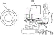
为了对本申请技术方案更好进行理解,首先对本申请的医生端手术控制设备所应用的场景进行介绍。如图1所示,为实际的微创手术的场景示意图。在该执行环境中,包含有图像台车、患者操作端和医生操作端。患者操作端对应于手术机器人,手术机器人可以包含多个机械臂,这些机械臂可以用于夹持相应的手术器械或内窥镜等设备。机械臂可以带动手术器械或内窥镜进行运动,从而在手术过程中查看不同视角下的患者体内状况,或是执行相应的手术操作。In order to better understand the technical solution of the present application, firstly, the application scenarios of the doctor-side surgical control device of the present application are introduced. As shown in FIG. 1 , it is a schematic diagram of an actual minimally invasive surgery scene. In this execution environment, there are image trolley, patient operation terminal and doctor operation terminal. The patient operation end corresponds to the surgical robot, and the surgical robot may include multiple mechanical arms, and these mechanical arms may be used to clamp corresponding surgical instruments or endoscopes and other equipment. The robotic arm can drive surgical instruments or endoscopes to move, so as to view the internal conditions of the patient from different perspectives during the operation, or perform corresponding surgical operations.
图像台车可以与内窥镜相连接,以将内窥镜拍摄到的图像在显示屏上展示,供其他医护人员查看。图像台车也具有一定的图像处理能力,进而展示对图像进行处理后的相关信息。The image trolley can be connected with the endoscope to display the images captured by the endoscope on the display screen for other medical staff to view. The image trolley also has certain image processing capabilities, and then displays relevant information after image processing.
医生操作端为医生操作的终端设备,通过接收图像台车传输的图像信号,使得医生能够观察内窥镜拍摄到的图像,了解患者体内当前的手术执行状况。医生操作端也能够对患者操作端上的机械臂进行控制,以实现调整内窥镜观察视角,以及利用手术器械执行特定的操作等。The doctor operation terminal is the terminal equipment operated by the doctor. By receiving the image signal transmitted by the image trolley, the doctor can observe the images captured by the endoscope and understand the current operation status in the patient's body. The doctor's operating end can also control the robotic arm on the patient's operating end to adjust the viewing angle of the endoscope and perform specific operations with surgical instruments.
但是,目前医生操作端在展示内窥镜拍摄到的图像时,往往是基于立体沉浸式的显示设备进行图像展示。这种显示设备一般通过固定的显示器来展示图像,当医生在手术过程中长时间注视屏幕时,容易造成医生的身体疲劳和用眼疲劳,此外,这种显示方式也无法适应不同医生或其他医护人员的需求,影响了医生的手术体验。However, when displaying the images captured by the endoscope at the doctor's operating terminal, the image display is often based on a three-dimensional immersive display device. This kind of display device generally displays images through a fixed monitor. When the doctor stares at the screen for a long time during the operation, it is easy to cause the doctor's physical fatigue and eye fatigue. In addition, this display method cannot adapt to different doctors or other medical care. The demand for personnel affects the doctor's surgical experience.
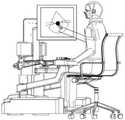
为了解决上述技术问题,介绍本说明书实施例一种医生端手术控制设备100。如图2A所示,所述医生端手术控制设备包括固定支架110、第一连接结构121、第二连接结构122、第一显示装置131、第二显示装置132和驱动电机(图中未示出)。In order to solve the above technical problems, a
固定支架为相对于所述医生端手术控制设备固定的支架,用于基于所述固定支架设置连接结构和显示装置。固定支架可以如图3A中所示,为竖直状态的柱状结构,也可以是其他形状或安装方式的结构。实际应用中所述固定支架只需能够有效支撑连接结构和显示装置即可,对其形状、位姿和安装部位等均不做限定。The fixed bracket is a bracket fixed relative to the surgical control device at the doctor's end, and is used for setting a connection structure and a display device based on the fixed bracket. The fixing bracket can be a columnar structure in a vertical state as shown in FIG. 3A , or it can be a structure of other shapes or installation methods. In practical applications, the fixing bracket only needs to be able to effectively support the connecting structure and the display device, and there is no limitation on its shape, posture and installation position.
第一连接结构用于连接固定支架和第一显示装置;第二连接结构用于连接固定支架和第二显示装置。连接结构能够基于固定支架进行伸缩和/或旋转,以达到将显示装置移动至任意空间位置的效果。连接结构可以由多个子结构组成,以同时达到球形范围内转动以及水平方向上伸缩的效果。The first connecting structure is used for connecting the fixing bracket and the first display device; the second connecting structure is used for connecting the fixing bracket and the second display device. The connection structure can be stretched and/or rotated based on the fixed bracket, so as to achieve the effect of moving the display device to any spatial position. The connection structure can be composed of multiple substructures to simultaneously achieve the effect of rotation within the spherical range and expansion and contraction in the horizontal direction.
具体的,所述连接结构可以包括球形转动结构、凹凸槽结构和伸缩杆结构中的至少一种。球形转动结构能够基于连接关节处在一定的弧面范围内进行转动,凹凸槽结构通过凹槽和凸槽之间的卡合,使得不同部位之间能够基于凹凸槽进行滑动。伸缩杆结构用于在伸缩杆连接方向进行水平伸缩。实际应用中为了保证连接结构的有效活动还可以设置其他子结构,并不限于上述示例。Specifically, the connection structure may include at least one of a spherical rotation structure, a concave-convex groove structure, and a telescopic rod structure. The spherical rotating structure can rotate within a certain arc range based on the connecting joint, and the concave-convex groove structure enables sliding between different parts based on the concave-convex groove through the engagement between the groove and the convex groove. The telescopic rod structure is used for horizontal expansion and contraction in the connection direction of the telescopic rod. In practical applications, other substructures may also be set in order to ensure effective activities of the connection structure, which is not limited to the above example.
如图3A所示,为通过第一连接结构连接第一显示装置的示意图。其中第一连接结构包括多个子结构,如图3A所示,所述第一连接结构包括第一固定子结构121-1、第一伸缩子结构121-2和第一转动子结构121-3。第一固定子结构121-1能够基于固定支架110进行伸缩,第一伸缩子结构121-2能够基于第一固定子结构121-1进行伸缩,第一转动子结构121-3连接第一伸缩子结构121-2和第一显示装置131,使得第一显示装置131能够相较于第一伸缩子结构121-2进行转动,进而达到对第一显示装置131的方位进行调节的效果。As shown in FIG. 3A , it is a schematic diagram of connecting the first display device through the first connection structure. The first connection structure includes a plurality of substructures, as shown in FIG. 3A , the first connection structure includes a first fixed substructure 121-1, a first telescopic substructure 121-2, and a first rotating substructure 121-3. The first fixed substructure 121-1 can expand and contract based on the fixed
如图3B所示,为通过第二连接结构122连接第二显示装置132的示意图。第二连接结构122也包含多个子结构,如图3B所示,所述第二连接结构包括第二凹凸槽子结构122-1、第二固定子结构122-2、第二伸缩子结构122-3和第二旋转子结构122-4。其中,第二凹凸槽子结构122-1为凹凸槽结构,使得第二固定子结构122-2能够相较于固定支架110进行俯仰方向的调节,第二固定子结构122-2与第二伸缩子结构122-3之间能够相互伸缩,从而实现水平方向上的延展与收回,第二显示装置132基于第二旋转子结构122-4与第二伸缩子结构122-3相连,使得第二显示装置132能够相较于第二伸缩子结构122-3进行转动,从而也达到了对第二显示装置132的方位进行调节的效果。As shown in FIG. 3B , it is a schematic diagram of connecting the
上述示意图中只是示例性的对第一连接结构121和第二连接结构122以及其中的子结构进行描述,实际应用中可以根据需求对具体的结构进行调整,在此不再赘述。The above schematic diagram is only an exemplary description of the
在第一显示装置131和第二显示装置132分别基于第一连接结构121和第二连接结构122与固定支架110相连时,第一显示装置131和第二显示装置132的位置可以根据需要进行调节。例如,所述第一显示装置131和第二显示装置132可以同时朝向医生所处的位置,如图2A所示,为第一显示装置131和第二显示装置132同时朝向医生的同时水平排布的情况,如图2B所示,为第一显示装置131和第二显示装置132同时朝向医生的同时竖直排布的情况。此外,第一显示装置131或第二显示装置132也可以被调节至朝向侧方位,供除操作医生外的其他医护人员查看,例如,如图2C所示,为将第二显示装置132朝向左侧的示意图,如图2D所示,为将第一显示装置131朝向右侧的示意图。实际应用中可以根据需求进行其他形式的调整,对此不做限制。When the
第一显示装置131和第二显示装置132可以用于展示图像或数据信息。在本说明书实施例中,应用至手术环境中时,第一显示装置131和第二显示装置132可以用于展示手术图像、手术执行流程、患者状态数据等。所述第一显示装置131和第二显示装置132具体展示的内容可以根据实际应用的需求进行设置,对此不做限制。The
优选的,第一显示装置131和第二显示装置132可以用于展示裸眼三维图像。所述第一显示装置131和第二显示装置132为开放式显示屏,通过展示裸眼三维图像使得展示给医生的患者体内图像的立体效果更为逼真。Preferably, the
其中,所展示的裸眼三维图像的成像过程可以是通过光栅或透镜对需要进行显示的图像进行分光。当基于光栅原理展示三维图像时,第一显示装置131和第二显示装置132利用狭缝光栅进行显示,狭缝可以对显示的内容进行遮挡,到达人眼的光线经一定距离后被分开,具有视差的两幅图像就会映入人眼,产生具有立体效果的三维图像。透镜原理与光栅原理较为相似,在此不再赘述。Wherein, the imaging process of the displayed three-dimensional naked-eye image may be to split the light of the image to be displayed through a grating or a lens. When displaying a three-dimensional image based on the grating principle, the
在实际应用中,医生端手术控制设备100与图像台车相连接。图像台车连接有内窥镜,用于探入患者体内获取患者体内图像。图像台车将内窥镜拍摄到的图像数据发送至医生端手术控制设备100后,由医生端手术控制设备100根据图像数据构建左右眼视差图像,并在第一显示装置131和/或第二显示装置132上进行展示。当人体在观看左右眼视差图像时,经由视神经的中枢融合反射,会产生视觉心理反应,从而产生三维立体感,形成裸眼3D的效果。In practical applications, the
在一些实施方式中,第一显示装置131和/或第二显示装置132上设置有受力传感器140。受力传感器140可以用于获取对应的显示装置的受力状态信息。受力状态信息包括受力大小和受力方向。In some implementations, a
相应的,在第一连接结构121和/或第二连接结构122上可以设置有驱动电机。驱动电机可以设置在连接结构的相应关节处,以达到驱动连接结构转动或伸缩的效果。相应的,驱动电机能够基于受力状态信息来推动第一连接结构121和/或第二连接结构122移动进而带动第一显示装置131和/或第二显示装置132进行移动。具体的,可以是将对应的显示装置朝受力方向进行移动,并基于受力大小来控制移动速度。Correspondingly, a driving motor may be provided on the
在实际应用中,虽然驱动电机可以将显示装置移动至固定位置,但医生基于自身需求可能需要对三维显示装置的位置进行微调。若希望调整第一显示装置131或第二显示装置132的位置,医生或其他医护人员可以向对应的显示装置施加一个力,例如,当医生希望第一显示装置131稍向左偏,可以在第一显示装置131的左侧施加一个力,受力传感器140相应的获取受力状态信息,即施加于第一显示装置上的力的大小和方向。In practical applications, although the drive motor can move the display device to a fixed position, doctors may need to fine-tune the position of the three-dimensional display device based on their own needs. If it is desired to adjust the position of the
受力传感器140可以将所获取到的受力状态信息发送至驱动电机,使得驱动电机能够基于所述受力状态信息带动对应的显示装置进行移动。例如,当医生希望第一显示装置131向左偏转时,驱动电机可以驱动第一连接结构121中的球形转动结构向左转动,从而使得第一显示装置131能够向左转动。The
具体的,驱动电机带动第一显示装置131和/或第二显示装置132进行移动,可以是在确定受力方向后,由驱动电机直接带动所述第一显示装置131和/或第二显示装置132向所述受力方向进行移动;也可以是利用驱动电机消除所述第一显示装置131和/或第二显示装置132在移动时所受到的所述受力方向上的阻力,使得医生在移动对应的显示装置时更为平滑,同时也保证了显示装置的最终移动位置更符合医生的实际需求。Specifically, the driving motor drives the
在一些实施方式中,所述受力传感器140包括六轴力传感器。所述六轴力传感器用于获取三个坐标方向上的力信息和扭矩信息,并将这些信息传输至处理器,使得处理器能够根据力信息和扭矩信息来计算受力矢量信息。受力矢量信息即包括受力大小和受力方向。其中,受力方向可以是空间矢量的形式。六轴力传感器共安装有六个硅应变传感器,且六轴力传感器满足静态数据模型F=CV,式中,F为计算的六路力信息,C为标定矩阵,V为六轴力传感器输出的六路原始信息。In some embodiments, the
其中,针对上述模型中的标定矩阵,可以通过对数据进行采样来获取。当外力施加在显示装置上时,对应的六轴力传感器上会被施加广义的一个力的矢量组。通过获取六路力信息F和通过数据采样得到的传感器六个输出信号矢量组V,即可求出上述模型中的标定矩阵C。由于传感器的输出信号是一个六路电压信号组成的矢量,只需要给传感器施加六个线性无关的矢量(忽略所有非线性因素影响),并测得对应六个力矢量的传感器的输出电压信号矢量,即可求得标定矩阵C的唯一解。Wherein, the calibration matrix in the above model can be obtained by sampling the data. When an external force is applied to the display device, a generalized force vector group will be applied to the corresponding six-axis force sensor. The calibration matrix C in the above model can be obtained by obtaining the six-way force information F and the six output signal vector groups V of the sensor obtained through data sampling. Since the output signal of the sensor is a vector composed of six voltage signals, it is only necessary to apply six linearly independent vectors to the sensor (ignoring the influence of all nonlinear factors), and measure the output voltage signal vector of the sensor corresponding to the six force vectors, The unique solution of the calibration matrix C can be obtained.
具体的模型对应的公式可以是
当计算得到标定矩阵后,在实际应用中,即可确定对应的显示装置的受力矢量信息,进而达到利用电机带动显示装置移动或是消除显示装置移动过程中的阻力的效果。After the calibration matrix is calculated, in practical applications, the force vector information of the corresponding display device can be determined, and then the effect of using the motor to drive the display device to move or eliminating the resistance during the movement of the display device can be achieved.
如图4所示,为六轴力传感器140的截面图和设置位置的示意图。其中,六轴力传感器140可以设置在连接结构与显示装置连接的部位,也可以直接设置在连接结构上。实际应用中对于六轴力传感器的具体设置位置不做限定,只要能够准确有效地对显示装置的受力状态信息进行测量即可As shown in FIG. 4 , it is a cross-sectional view of the six-
如图5所示,为显示装置的支撑轴160的结构示意图。所述支撑轴可以为独立于连接结构的部件,也可以为连接结构的一部分或全部组成部分,共同起到对显示装置进行调节的效果。其中,显示装置的整体支撑轴160由固定支架底端161、升降立柱162和若干个旋转关节163连接组成。固定支架底端161与升降立柱162相连接,可以进行上下调整;升降立柱162的第一段轴和第二段轴之间为可伸缩结构,可以进行前后调整。其余各个旋转关节163可以在各自平面内进行360°的自由旋转,以达到将显示装置调整至任意方向任意位置的效果。实际应用中可以对支撑轴160的结构进行调整,并不限于图中的结构,对此不做限制。As shown in FIG. 5 , it is a schematic structural diagram of the
六轴力传感器140基于其截面结构安装在支撑轴内的轮毂中,通过梁进行连接,每根梁包含有若干个硅应变片,硅应变片通过成对工作构成半桥电路,输出六路电压值,在经过数模装换和相应的逻辑后,输出力和力矩值,进而转化为力信息和扭矩信息,最终基于上述模型进行计算,即得到详细的力矢量信息,使得能够结合所述力矢量信息对显示装置进行调整。The six-
由于连接结构本身可旋转或伸缩,若不对其进行固定则有可能会导致显示装置位移或松脱,影响使用效果。因此,在一些实施方式中,所述设备还可以包括安全控制模块,安全控制模块用于通过算法锁死和/或机械抱闸的方式对所述第一显示装置131和/或第二显示装置132进行锁定。算法锁死可以是通过相应的内置函数,使得驱动电机不会再带动三维显示装置110进行移动,机械抱闸可以是通过相应的机械结构直接对三维显示装置进行固定,保证三维显示装置110在手术过程中不会松动,确保医生的手术执行效果。Since the connection structure itself can be rotated or stretched, if it is not fixed, the display device may be displaced or loosened, which will affect the use effect. Therefore, in some implementations, the device may further include a safety control module, which is used to lock the
具体的,所述设备可以是在检测到第一显示装置131和/或第二显示装置132没有受力的情况下,认定当前不存在对显示装置进行移动的需求,可以利用安全控制模块对显示装置进行锁定;也可以是额外设置位置传感器,用于分别获取第一显示装置131的第一空间位置和/或第二显示装置132的第二空间位置。在检测到所述第一空间位置符合第一绝对位置和/或第二空间位置符合第二绝对位置的情况下,通过所述安全控制模块对第一显示装置131和/或第二显示装置132进行锁定。第一绝对位置和第二绝对位置可以是预先确定的位置,例如根据医生的使用习惯所确定的默认位置。当检测到处于该位置时,自动对显示装置进行锁定,以提高使用体验。Specifically, when the device detects that the
相应的,当医生输入移动指令或是推动显示装置时,可以自动解除锁定,以保证对显示装置的正常移动。Correspondingly, when the doctor inputs a movement command or pushes the display device, the lock can be automatically released to ensure normal movement of the display device.
在一些实施方式中,为了提高设备的便利性,所述第一显示装置131和/或第二显示装置132上设置有摄像装置。摄像装置能够进行拍摄,并对拍摄图像进行人脸识别。例如,当医生或医护人员位于拍摄范围内时,可以识别出拍摄图像中的医生或医护人员的人脸。相应的,根据识别出的人脸可以确定人脸位置或人眼注视方向。所述人脸位置或人眼注视方向可以是在确定显示设备的空间位置后,针对显示设备的空间位置的相对位置,以方便后续对显示设备进行移动。In some implementations, in order to improve the convenience of the device, the
在确定人脸位置或人眼注视方向后,医生端手术控制设备可以控制所述第一显示装置131和/或第二显示装置132移动以朝向所述人脸位置或人眼注视方向,进而方便医生或医护人员更好地观看对应的显示装置。具体的可以是基于人脸位置或人眼注视方向与当前显示装置的空间位置计算出显示装置的移动路径和转动角度,再根据所述移动路径和转动角度调用驱动电机对连接结构进行驱动,达到移动显示装置的效果。After determining the position of the human face or the gaze direction of the human eyes, the surgical control device at the doctor end can control the
通过这一实施方式能够自动对显示装置的位置进行调节,以适应医生或医护人员的观看,提高了使用体验,优化了手术操作环境。Through this embodiment, the position of the display device can be automatically adjusted to adapt to the viewing of doctors or medical staff, which improves the user experience and optimizes the operation environment.
在一些实施方式中,为了便于多名不同医生对所述医生端手术控制设备100的有效使用,所述设备还可以包括身份认证装置。身份认证装置用于确定当前使用者的用户身份,并查找是否预先存储有对应于所述用户身份的第一绝对位置和/或第二绝对位置。若存在,驱动电机可以直接带动所述第一显示装置131和/或第二显示装置132移动至所述第一绝对位置和/或第二绝对位置。In some implementations, in order to facilitate effective use of the doctor-end
身份认证装置不一定是额外设置在医生端手术控制设备100上的装置,例如,在身份认证方式为账户登录认证时,身份认证装置可以集成于第一显示装置131和/或第二显示装置132中,用户可以直接通过第一显示装置131和/或第二显示装置132输入对应的账号和密码信息,进而实现身份认证。当身份认证装置为基于生物信息识别、红外识别等方式进行身份认证时,所述身份认证装置可以是在设备上额外设置的认证设备。例如,当认证方式为指纹识别认证时,身份认证装置可以为指纹采集装置;当认证方式为瞳孔识别时,身份认证装置可以为高清照相机;当认证方式为红外识别时,身份认证装置可以为红外发射器。具体的对于身份认证装置的类型可以基于认证方式进行确定,在此不再赘述。The identity authentication device is not necessarily an additional device installed on the doctor-side
具体的,医生在初次使用设备时,在设备上创建私人账号,并通过账号密码或生物信息等方式进行身份认证。相应的,在登录私人账号后,可以通过调节第一显示装置131和/或第二显示装置132使得第一显示装置131和/或第二显示装置132的移动至相应位置,使其位姿符合医生的需求。在医生确认后,设备可以记录当前第一显示装置131和/或第二显示装置132的位姿,并作为第一绝对位置和/或第二绝对位置与该用户的账号进行同步保存。在医生需要执行手术时,可以在设备上登录私人账号,设备可以调取私人账号所对应的预存储的显示装置位置,发送至驱动电机,由驱动电机将第一显示装置131和/或第二显示装置132调整至对应的位姿,进而方便不同用户对所述医生端手术控制设备100的使用,提高用户的使用体验。Specifically, the doctor creates a private account on the device when using the device for the first time, and performs identity authentication through account password or biometric information. Correspondingly, after logging in the private account, the
在一些实施方式中,所述第一显示装置131和/或所述第二显示装置132的屏幕为可交互式的屏幕,例如为触控屏幕,即所述第一显示装置131和/或所述第二显示装置132还包括触摸感应单元和显示控制单元。In some implementations, the screen of the
所述触摸感应单元用于根据用户对第一显示装置131和/或所述第二显示装置132的显示屏幕的触碰生成触摸感应信号,所述显示控制单元用于根据触摸感应信号调整第一显示装置131和/或所述第二显示装置132的展示图像或展示对应与所述触摸感应信号的标记。The touch sensing unit is used to generate a touch sensing signal according to the user's touch on the display screen of the
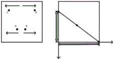
所述触摸感应信号可以为双指移动信号,即利用两个手指在屏幕上相背而动或相向而动,进而实现对于第一显示装置131和/或所述第二显示装置132的展示图像的放大或缩小。例如,如图6所示,当医生需要仔细查看拍摄到的图像中的组织时,可以利用双指进行放大操作,进而放大图像;当需要查看患者体内的全景图像时,可以利用双指进行缩小操作,以扩大查看到的图像的范围。The touch sensing signal may be a two-finger movement signal, that is, using two fingers to move away from each other or towards each other on the screen, thereby realizing display images for the
如图7所示,为双指触控过程中的一个具体示例。其中,当两个手指同时触控时,当两个手指同时触控时,由C点、D点向一起合拢时为缩小操作,算法执行缩小画面操作;由A点、B点向外拉开时,为放大操作,由算法执行放大操作。当两个手指放置在触摸屏时,可计算出两手之间中心点坐标位置,此时假设两点坐标分别为A(X1,Y1)、B(X2,Y2)则这两点所对应的中心点的坐标为Z[(X1+X2)/2,(Y1+Y2)/2],此时无论朝哪个方向拉伸,均可利用勾股定理计算出两点间距离,从而执行相应的操作。As shown in FIG. 7 , it is a specific example of the two-finger touch process. Among them, when two fingers are touched at the same time, when two fingers are touched at the same time, when the points C and D are closed together, it is a zoom-out operation, and the algorithm performs the operation of zooming out the screen; pull out from points A and B When , it is a zoom-in operation, and the zoom-in operation is performed by the algorithm. When two fingers are placed on the touch screen, the coordinate position of the center point between the two hands can be calculated. At this time, assuming that the coordinates of the two points are A(X1,Y1) and B(X2,Y2) respectively, then the center point corresponding to the two points The coordinates of are Z[(X1+X2)/2,(Y1+Y2)/2], at this time, no matter which direction you stretch, you can use the Pythagorean theorem to calculate the distance between two points, so as to perform corresponding operations.
所述触摸感应信号也可以是单指移动信号。当医生利用单指在屏幕上移动时,可以将单指移动信号所对应的轨迹以标记绘画的形式在展示图像上进行体现。在手术过程中,医生可能需要标记一些重点区域给其他医护人员进行查看,而添加标记绘画的形式能够保证两者之间的有效沟通,使得其他医护人员能够更为直观便捷地了解医生的意图。The touch sensing signal may also be a single-finger movement signal. When the doctor uses a single finger to move on the screen, the trajectory corresponding to the single finger movement signal can be reflected on the display image in the form of a marker drawing. During the operation, the doctor may need to mark some key areas for other medical staff to view, and adding the form of marker drawing can ensure effective communication between the two, so that other medical staff can understand the doctor's intention more intuitively and conveniently.
具体的,所述触摸感应单元可以包括电阻技术触摸屏、电容技术触摸屏、红外技术触摸屏、表面声波触摸屏中的一种。实际应用中可以根据需求进行选取,对此不做限制。Specifically, the touch sensing unit may include one of a resistive technology touch screen, a capacitive technology touch screen, an infrared technology touch screen, and a surface acoustic wave touch screen. In practical applications, it can be selected according to requirements, and there is no limitation on this.
此外,由于医生端手术控制设备100与图像台车相连接,在医生端手术控制设备100上展示图像或是医生针对图像进行标记时,医生端手术控制设备100还可以将展示图像和/或标记同步在图像台车上进行展示,使得其他医护人员也能够根据图像台车确定当前的手术状况,保证手术的有效实施。In addition, since the doctor-side
由于在手术过程中显示装置与医生之间的距离不固定,触控的方式对显示装置进行操作可能存在一定的不便,因此,为了优化针对显示装置的操作,在第一显示装置131和/或第二显示装置132上还可以设置摄像装置,用于拍摄医生或医护人员的手势动作。在拍摄得到手势动作后,可以对手势动作进行识别,并基于识别得到的手势动作结果对展示图像进行调节。例如,在手势动作为两指拉开的动作时,可以对图像进行放大,在手势动作为两指缩进的动作时,可以对图像进行缩小。实际应用中可以根据需要设置对应的手势动作与图像操作之间的对应关系,在此不再赘述。Since the distance between the display device and the doctor is not fixed during the operation, it may be inconvenient to operate the display device by touch. Therefore, in order to optimize the operation of the display device, the
由于所展示的图像为3D图像,医生在长时间观看3D图像的情况下,可能会产生眩晕感。眩晕感可能是因为运动视差、双眼视差、辐辏和调焦等因素导致,尤其是辐辏和调焦,使得原虚拟物体看起来有无限个距离的数值,但是焦距是固定的,所以会产生辐辏冲突,进而使人产生眩晕感。Since the displayed image is a 3D image, the doctor may feel dizzy when watching the 3D image for a long time. Vertigo may be caused by factors such as motion parallax, binocular parallax, convergence and focus, especially convergence and focus, making the original virtual object seem to have infinite distance values, but the focal length is fixed, so convergence conflicts will occur , causing dizziness.
为了缓解手术过程中的眩晕感,所述设备还包括防眩晕眼镜150。如图8所示,为所述防眩晕眼镜150的结构示意图。防眩晕眼镜150包括调节旋钮152和镜片151。调节旋钮152用于调节镜片151对应的度数,通过左旋或右旋可以实现远视度数调节和近视度数调节。在度数调节适当的情况下,医生通过镜片151观察到的双目图像平行,从而缓解上下视差导致的眩晕。In order to alleviate the feeling of vertigo during the operation, the device also includes
实际应用中,所述防眩晕眼镜150可以放置在适当的位置,例如医生端手术控制台的上面、下面、左面、右面、以及术者椅子等各个方向等,以便于医生的取用,对此不做限制。In practical applications, the
需要说明的是,虽然本说明书实施例中仅给出了包含第一显示装置131和第二显示装置132的方案介绍,但是,在医生端手术控制设备中包含有两个以上显示装置时,也可以基于本申请的技术构思来设置所述医生端手术控制设备,即在医生端手术控制设备上设置多个连接结构和显示装置的方式仍属于本申请所要求保护的范围内。It should be noted that although the embodiment of this specification only gives an introduction to the solution including the
通过上述实施例的介绍可以看出,所述医生端手术控制设备同时包含第一显示装置和第二显示装置,且第一显示装置和第二显示装置分别基于第一连接结构和第二连接结构可以调节自身的空间位置和朝向,在医生或其他医护人员存在相应需求时,可以对第一显示装置和第二显示装置的位置进行调整,例如将两个显示装置同时朝向医生,或是将其中一个显示装置朝向医生,另一个显示装置朝向医护人员的位置。此外,在医生端手术控制设备包含驱动电机的情况下,向设备中输入移动指令后,可以通过驱动电机来带动第一显示装置和/或第二显示装置移动至对应于移动指令的空间位置,进而实现显示装置的位置的自动调节。通过上述设备,能够通过两个显示装置展示相应的图像和信息,并能够基于手术需求调节显示装置的空间位置,满足了不同的手术需求。此外,利用驱动电机对连接结构进行驱动也能够自动对显示装置的位置进行控制,保证了显示装置移动的精确性,提高了手术过程中的体验,有利于手术的有效进行。It can be seen from the introduction of the above embodiments that the doctor-side surgical control device includes both a first display device and a second display device, and the first display device and the second display device are based on the first connection structure and the second connection structure respectively It can adjust its own spatial position and orientation. When doctors or other medical personnel have corresponding needs, they can adjust the positions of the first display device and the second display device. For example, the two display devices face the doctor at the same time, or the One display is oriented toward the doctor and the other is oriented toward the position of the medical staff. In addition, in the case where the surgical control device at the doctor's end includes a drive motor, after a movement command is input into the device, the drive motor can be used to drive the first display device and/or the second display device to move to a spatial position corresponding to the movement command, Furthermore, the automatic adjustment of the position of the display device is realized. Through the above-mentioned device, corresponding images and information can be displayed through two display devices, and the spatial position of the display devices can be adjusted based on surgical requirements, thus meeting different surgical requirements. In addition, using the drive motor to drive the connection structure can also automatically control the position of the display device, which ensures the accuracy of the movement of the display device, improves the experience during the operation, and is conducive to the effective operation of the operation.
基于上述医生端手术控制设备,本说明书实施例还提出一种针对医生端手术控制设备的控制方法。所述针对医生端手术控制设备的控制方法的执行主体可以是所述医生端手术控制设备。如图9所示,所述针对医生端手术控制设备的控制方法包括以下具体实施步骤。Based on the above-mentioned surgical control device at the doctor's end, the embodiment of this specification also proposes a control method for the surgical control device at the doctor's end. The subject of execution of the control method for the doctor-side surgical control device may be the doctor-side surgical control device. As shown in FIG. 9 , the control method for the surgical control device at the doctor end includes the following specific implementation steps.
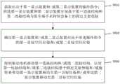
S910:获取对应于第一显示装置和/或第二显示装置的操作指令;所述第一显示装置和第二显示装置分别基于第一连接结构和第二连接结构与医生端手术控制设备上的固定支架连接。S910: Obtain an operation instruction corresponding to the first display device and/or the second display device; the first display device and the second display device are respectively based on the first connection structure and the second connection structure and the operation control device on the doctor's end Fixed bracket connection.
对于第一显示装置、第二显示装置、固定支架、第一连接结构、第二连接结构的结构特征以及连接关系可以参照上述医生端手术控制设备的实施例中的描述,在此不再重复描述。For the structural features and connection relationship of the first display device, the second display device, the fixing bracket, the first connection structure, and the second connection structure, please refer to the description in the embodiment of the surgical control device at the doctor's end above, and will not repeat the description here. .
操作指令用于指示调节第一显示装置和第二显示装置的空间位姿,可以是将显示装置移动至新的位置,也可以是调节显示装置的转向。The operation instruction is used to instruct to adjust the spatial pose of the first display device and the second display device, which may be moving the display device to a new position, or adjusting the direction of the display device.
在一些实施方式中,所述操作指令可以是由医生直接输入的指令。例如,在设备中预先设置有对应于第一显示装置的第一绝对位置和第二绝对位置。医生可以直接基于设备的输入模块选择对应于第一显示装置的第一绝对位置和/或对应于第二显示装置的第二绝对位置。其中,在包含有多个第一绝对位置或多个第二绝对位置的情况下,还涉及医生对于第一绝对位置和/或第二绝对位置的进一步选取。In some implementations, the operation instruction may be an instruction directly input by a doctor. For example, a first absolute position and a second absolute position corresponding to the first display device are preset in the device. The doctor can select the first absolute position corresponding to the first display means and/or the second absolute position corresponding to the second display means directly based on the input means of the device. Wherein, in the case of including multiple first absolute positions or multiple second absolute positions, further selection of the first absolute position and/or the second absolute position by the doctor is also involved.
在获取到医生针对第一绝对位置和/或第二绝对位置的选取操作,即可根据所述选取操作生成操作指令。在本实施方式中,操作指令用于指示将第一显示装置移动至第一绝对位置和/或将第二显示装置移动至第二绝对位置。具体的,可以是先基于位置传感器获取第一显示装置和/或第二显示装置的当前位置,再根据当前位置与绝对位置确定矢量距离,进而根据矢量距离确定连接结构的移动方式,从而能够控制驱动装置对连接结构进行移动,进而使其基于所述矢量距离控制显示装置进行移动。After the doctor's selection operation on the first absolute position and/or the second absolute position is acquired, an operation instruction can be generated according to the selection operation. In this embodiment, the operation instruction is used to instruct to move the first display device to a first absolute position and/or to move the second display device to a second absolute position. Specifically, the current position of the first display device and/or the second display device may be obtained based on the position sensor, and then the vector distance is determined according to the current position and the absolute position, and then the movement mode of the connection structure is determined according to the vector distance, so that the control The driving device moves the connection structure, and then controls the display device to move based on the vector distance.
相应的,所述选取操作可以是医生对显示装置进行触碰操作后直接选取的指令。对于触碰操作以实现医生与显示装置之间的交互的描述可以参照医生端手术控制设备的描述,在此不再赘述。Correspondingly, the selection operation may be an instruction directly selected by the doctor after the touch operation is performed on the display device. For the description of the touch operation to realize the interaction between the doctor and the display device, reference may be made to the description of the surgical control device at the doctor's end, which will not be repeated here.
在一些实施方式中,所述操作指令还可以直接根据医生对显示装置的拉扯和推动而触发。具体的,所述第一显示装置和/或第二显示装置上设置有受力传感器,用于获取相应的受力状态信息。对于受理传感器和受力状态信息的详细描述可以参照医生端手术控制设备的实施例中的描述。In some implementations, the operation instruction can also be directly triggered according to pulling and pushing of the display device by the doctor. Specifically, the first display device and/or the second display device is provided with a force sensor for acquiring corresponding force state information. For a detailed description of the acceptance sensor and force status information, reference may be made to the description in the embodiment of the surgical control device at the doctor's end.
在受力状态信息包括受力大小和受力方向的情况下,基于受力大小和受力方向可以生成操作指令。所述操作指令可以用于控制显示装置按照对应于受力大小的速度和对应于受力方向的方向进行移动,同样能够实现对于显示装置的移动控制。In the case that the force status information includes the magnitude and direction of the force, an operation instruction can be generated based on the magnitude and direction of the force. The operation instruction can be used to control the display device to move according to the speed corresponding to the magnitude of the force and the direction corresponding to the direction of the force, which can also realize the movement control of the display device.
S920:确定第一显示装置和/或第二显示装置对应于所述操作指令的第一目标位姿和/或第二目标位姿。S920: Determine a first target pose and/or a second target pose of the first display device and/or the second display device corresponding to the operation instruction.
第一目标位姿和第二目标位姿可以是基于操作指令所需要将第一显示装置和第二显示装置移动的位置和空间姿态。The first target pose and the second target pose may be positions and spatial poses where the first display device and the second display device need to be moved based on the operation instruction.
在获取到操作指令后,即可确定操作指令对应的第一显示装置和/或第二显示装置的第一目标位姿和/或第二目标位姿。具体的,在操作指令直接对应绝对位置的情况下,可以直接从操作指令中获取第一目标位姿和/或第二目标位姿。在操作指令对应于受力状态信息的情况下,所述第一目标位姿和/或第二目标位姿基于受力状态信息进行实时调整,以达到按照医生的操控将显示装置移动至目标位姿对应的位置的效果。After the operation instruction is acquired, the first target pose and/or the second target pose of the first display device and/or the second display device corresponding to the operation instruction can be determined. Specifically, in the case that the operation instruction directly corresponds to the absolute position, the first target pose and/or the second target pose may be obtained directly from the operation instruction. When the operation instruction corresponds to the force state information, the first target pose and/or the second target pose are adjusted in real time based on the force state information, so as to move the display device to the target position according to the doctor's manipulation. The effect of the position corresponding to the pose.
S930:控制驱动电机移动第一连接结构和/或第二连接结构,以使第一连接结构和/或第二连接结构基于固定支架伸缩和/或旋转来带动第一显示装置移动至第一目标控制位姿和/或带动第二显示装置移动至第二目标位姿。S930: Control the driving motor to move the first connection structure and/or the second connection structure, so that the first connection structure and/or the second connection structure are stretched and/or rotated based on the fixed bracket to drive the first display device to move to the first target controlling the pose and/or driving the second display device to move to a second target pose.
基于所述第一目标位姿和/或第二目标位姿,结合第一显示装置和/或第二显示装置的当前位置,可以确定对第一显示装置和/或第二显示装置的移动方向和转向角度,进而根据相应的转换逻辑将位移矢量转换为对应于驱动电机的驱动指令,以使驱动电机带动连接结构伸缩和/或旋转,达到将显示装置移动至对应位置的效果。具体的利用驱动电机带动连接结构的描述可以参照医生端手术控制设备的实施例中的描述,在此不再赘述。Based on the first target pose and/or the second target pose, combined with the current position of the first display device and/or the second display device, the direction of movement to the first display device and/or the second display device may be determined and the steering angle, and then convert the displacement vector into a driving command corresponding to the driving motor according to the corresponding conversion logic, so that the driving motor drives the connecting structure to expand and/or rotate, so as to achieve the effect of moving the display device to the corresponding position. The specific description of using the drive motor to drive the connection structure can refer to the description in the embodiment of the surgical control device at the doctor's end, and will not be repeated here.
基于图9所对应的针对医生端手术控制设备的控制方法,本说明书实施例提供一种计算机可读存储介质,其上存储有计算机程序/指令。所述计算机可读存储介质可以基于设备的内部总线被处理器所读取,进而通过处理器实现所述计算机可读存储介质中的程序指令。Based on the control method for the doctor-side surgical control device corresponding to FIG. 9 , the embodiment of this specification provides a computer-readable storage medium on which computer programs/instructions are stored. The computer-readable storage medium can be read by the processor based on the internal bus of the device, and then the program instructions in the computer-readable storage medium are implemented by the processor.
在本实施例中,所述计算机可读存储介质可以按任何适当的方式实现。所述计算机可读存储介质包括但不限于随机存取存储器(Random Access Memory,RAM)、只读存储器(Read-Only Memory,ROM)、缓存(Cache)、硬盘(Hard Disk Drive,HDD)、存储卡(MemoryCard)等等。所述计算机存储介质存储有计算机程序指令。在所述计算机程序指令被执行时实现本说明书图9所对应实施例的程序指令或模块。In this embodiment, the computer-readable storage medium may be implemented in any suitable manner. The computer-readable storage medium includes, but is not limited to, random access memory (Random Access Memory, RAM), read-only memory (Read-Only Memory, ROM), cache (Cache), hard disk (Hard Disk Drive, HDD), storage Card (MemoryCard) and so on. The computer storage medium stores computer program instructions. When the computer program instructions are executed, the program instructions or modules of the embodiment corresponding to FIG. 9 of this specification are implemented.
在本实施例中,所述处理器可以按任何适当的方式实现。例如,处理器可以采取例如微处理器或处理器以及存储可由该(微)处理器执行的计算机可读程序代码(例如软件或固件)的计算机可读介质、逻辑门、开关、专用集成电路(Application SpecificIntegrated Circuit,ASIC)、可编程逻辑控制器和嵌入微控制器的形式等等。具体的,所述处理器在被设置在医生端手术控制设备上时可以执行图9对应的实施例中的方法步骤。In this embodiment, the processor may be implemented in any suitable manner. For example, a processor may take the form of a microprocessor or a processor and a computer-readable medium storing computer-readable program code (such as software or firmware) executable by the (micro)processor, logic gates, switches, application specific integrated circuits ( Application SpecificIntegrated Circuit, ASIC), programmable logic controller and embedded microcontroller form and so on. Specifically, the processor may execute the method steps in the embodiment corresponding to FIG. 9 when it is set on the surgical control device at the doctor's end.
虽然上文描述的过程流程包括以特定顺序出现的多个操作,但是,应当清楚了解,这些过程可以包括更多或更少的操作,这些操作可以顺序执行或并行执行(例如使用并行处理器或多线程环境)。Although the process flows described above include multiple operations occurring in a particular order, it should be clearly understood that the processes may include more or fewer operations, which may be performed sequentially or in parallel (e.g., using parallel processors or multi-threaded environment).
本申请是参照根据本说明书实施例的方法、设备(系统)、和计算机程序产品的流程图和/或方框图来描述的。应理解可由计算机程序指令实现流程图和/或方框图中的每一流程和/或方框、以及流程图和/或方框图中的流程和/或方框的结合。可提供这些计算机程序指令到通用计算机、专用计算机、嵌入式处理机或其他可编程数据处理设备的处理器以产生一个机器,使得通过计算机或其他可编程数据处理设备的处理器执行的指令产生用于实现在流程图一个流程或多个流程和/或方框图一个方框或多个方框中指定的功能的装置。The present application is described with reference to flowcharts and/or block diagrams of methods, apparatus (systems), and computer program products according to embodiments of the specification. It should be understood that each procedure and/or block in the flowchart and/or block diagram, and a combination of procedures and/or blocks in the flowchart and/or block diagram can be realized by computer program instructions. These computer program instructions may be provided to a general purpose computer, special purpose computer, embedded processor, or processor of other programmable data processing equipment to produce a machine such that the instructions executed by the processor of the computer or other programmable data processing equipment produce a An apparatus for realizing the functions specified in one or more procedures of the flowchart and/or one or more blocks of the block diagram.
这些计算机程序指令也可存储在能引导计算机或其他可编程数据处理设备以特定方式工作的计算机可读存储器中,使得存储在该计算机可读存储器中的指令产生包括指令装置的制造品,该指令装置实现在流程图一个流程或多个流程和/或方框图一个方框或多个方框中指定的功能。These computer program instructions may also be stored in a computer-readable memory capable of directing a computer or other programmable data processing apparatus to operate in a specific manner, such that the instructions stored in the computer-readable memory produce an article of manufacture comprising instruction means, the instructions The device realizes the function specified in one or more procedures of the flowchart and/or one or more blocks of the block diagram.
这些计算机程序指令也可装载到计算机或其他可编程数据处理设备上,使得在计算机或其他可编程设备上执行一系列操作步骤以产生计算机实现的处理,从而在计算机或其他可编程设备上执行的指令提供用于实现在流程图一个流程或多个流程和/或方框图一个方框或多个方框中指定的功能的步骤。These computer program instructions can also be loaded onto a computer or other programmable data processing device, causing a series of operational steps to be performed on the computer or other programmable device to produce a computer-implemented process, thereby The instructions provide steps for implementing the functions specified in the flow chart or blocks of the flowchart and/or the block or blocks of the block diagrams.
在一个典型的配置中,计算设备包括一个或多个处理器(CPU)、输入/输出接口、网络接口和内存。In a typical configuration, a computing device includes one or more processors (CPUs), input/output interfaces, network interfaces, and memory.
内存可能包括计算机可读介质中的非永久性存储器,随机存取存储器(RAM)和/或非易失性内存等形式,如只读存储器(ROM)或闪存(flash RAM)。内存是计算机可读介质的示例。Memory may include non-permanent storage in computer readable media, in the form of random access memory (RAM) and/or nonvolatile memory such as read only memory (ROM) or flash RAM. Memory is an example of computer readable media.
计算机可读介质包括永久性和非永久性、可移动和非可移动媒体可以由任何方法或技术来实现信息存储。信息可以是计算机可读指令、数据结构、程序的模块或其他数据。计算机的存储介质的例子包括,但不限于相变内存(PRAM)、静态随机存取存储器(SRAM)、动态随机存取存储器(DRAM)、其他类型的随机存取存储器(RAM)、只读存储器(ROM)、电可擦除可编程只读存储器(EEPROM)、快闪记忆体或其他内存技术、只读光盘只读存储器(CD-ROM)、数字多功能光盘(DVD)或其他光学存储、磁盒式磁带,磁带磁磁盘存储或其他磁性存储设备或任何其他非传输介质,可用于存储可以被计算设备访问的信息。按照本文中的界定,计算机可读介质不包括暂存电脑可读媒体(transitory media),如调制的数据信号和载波。Computer-readable media, including both permanent and non-permanent, removable and non-removable media, can be implemented by any method or technology for storage of information. Information may be computer readable instructions, data structures, modules of a program, or other data. Examples of computer storage media include, but are not limited to, phase change memory (PRAM), static random access memory (SRAM), dynamic random access memory (DRAM), other types of random access memory (RAM), read only memory (ROM), Electrically Erasable Programmable Read-Only Memory (EEPROM), Flash memory or other memory technology, Compact Disc Read-Only Memory (CD-ROM), Digital Versatile Disc (DVD) or other optical storage, Magnetic tape cartridge, tape magnetic disk storage or other magnetic storage device or any other non-transmission medium that can be used to store information that can be accessed by a computing device. As defined herein, computer-readable media excludes transitory computer-readable media, such as modulated data signals and carrier waves.
本领域技术人员应明白,本说明书的实施例可提供为方法、系统或计算机程序产品。因此,本说明书实施例可采用完全硬件实施例、完全软件实施例或结合软件和硬件方面的实施例的形式。而且,本说明书实施例可采用在一个或多个其中包含有计算机可用程序代码的计算机可用存储介质(包括但不限于磁盘存储器、CD-ROM、光学存储器等)上实施的计算机程序产品的形式。Those skilled in the art should understand that the embodiments of this specification may be provided as methods, systems or computer program products. Accordingly, the embodiments of the present description may take the form of an entirely hardware embodiment, an entirely software embodiment or an embodiment combining software and hardware aspects. Furthermore, embodiments of the present description may take the form of a computer program product embodied on one or more computer-usable storage media (including but not limited to disk storage, CD-ROM, optical storage, etc.) having computer-usable program code embodied therein.
本说明书实施例可以在由计算机执行的计算机可执行指令的一般上下文中描述,例如程序模块。一般地,程序模块包括执行特定任务或实现特定抽象数据类型的例程、程序、对象、组件、数据结构等等。也可以在分布式计算环境中实践本说明书实施例,在这些分布式计算环境中,由通过通信网络而被连接的远程处理设备来执行任务。在分布式计算环境中,程序模块可以位于包括存储设备在内的本地和远程计算机存储介质中。Embodiments of the present specification may be described in the general context of computer-executable instructions, such as program modules, being executed by a computer. Generally, program modules include routines, programs, objects, components, data structures, etc. that perform particular tasks or implement particular abstract data types. Embodiments of the present description may also be practiced in distributed computing environments where tasks are performed by remote processing devices that are linked through a communications network. In a distributed computing environment, program modules may be located in both local and remote computer storage media including storage devices.
本说明书中的各个实施例均采用递进的方式描述,各个实施例之间相同相似的部分互相参见即可,每个实施例重点说明的都是与其他实施例的不同之处。尤其,对于系统实施例而言,由于其基本相似于方法实施例,所以描述的比较简单,相关之处参见方法实施例的部分说明即可。在本说明书的描述中,参考术语“一个实施例”、“一些实施例”、“示例”、“具体示例”、或“一些示例”等的描述意指结合该实施例或示例描述的具体特征、结构、材料或者特点包含于本说明书实施例的至少一个实施例或示例中。在本说明书中,对上述术语的示意性表述不必须针对的是相同的实施例或示例。而且,描述的具体特征、结构、材料或者特点可以在任一个或多个实施例或示例中以合适的方式结合。此外,在不相互矛盾的情况下,本领域的技术人员可以将本说明书中描述的不同实施例或示例以及不同实施例或示例的特征进行结合和组合。Each embodiment in this specification is described in a progressive manner, the same and similar parts of each embodiment can be referred to each other, and each embodiment focuses on the differences from other embodiments. In particular, for the system embodiment, since it is basically similar to the method embodiment, the description is relatively simple, and for relevant parts, refer to part of the description of the method embodiment. In the description of this specification, descriptions referring to the terms "one embodiment", "some embodiments", "example", "specific examples", or "some examples" mean that specific features described in connection with the embodiment or example , structures, materials or features are included in at least one embodiment or example of the embodiments of this specification. In this specification, the schematic representations of the above terms are not necessarily directed to the same embodiment or example. Furthermore, the described specific features, structures, materials or characteristics may be combined in any suitable manner in any one or more embodiments or examples. In addition, those skilled in the art can combine and combine different embodiments or examples and features of different embodiments or examples described in this specification without conflicting with each other.
以上所述仅为本申请的实施例而已,并不用于限制本申请。对于本领域技术人员来说,本申请可以有各种更改和变化。凡在本申请的精神和原理之内所作的任何修改、等同替换、改进等,均应包含在本申请的权利要求范围之内。The above descriptions are only examples of the present application, and are not intended to limit the present application. For those skilled in the art, various modifications and changes may occur in this application. Any modification, equivalent replacement, improvement, etc. made within the spirit and principle of the present application shall be included within the scope of the claims of the present application.
Claims (12)
Priority Applications (1)
| Application Number | Priority Date | Filing Date | Title |
|---|---|---|---|
| CN202211180460.8ACN115645054A (en) | 2022-09-27 | 2022-09-27 | A doctor-side surgical control device, control method and storage medium |
Applications Claiming Priority (1)
| Application Number | Priority Date | Filing Date | Title |
|---|---|---|---|
| CN202211180460.8ACN115645054A (en) | 2022-09-27 | 2022-09-27 | A doctor-side surgical control device, control method and storage medium |
Publications (1)
| Publication Number | Publication Date |
|---|---|
| CN115645054Atrue CN115645054A (en) | 2023-01-31 |
Family
ID=84985058
Family Applications (1)
| Application Number | Title | Priority Date | Filing Date |
|---|---|---|---|
| CN202211180460.8APendingCN115645054A (en) | 2022-09-27 | 2022-09-27 | A doctor-side surgical control device, control method and storage medium |
Country Status (1)
| Country | Link |
|---|---|
| CN (1) | CN115645054A (en) |
Citations (9)
| Publication number | Priority date | Publication date | Assignee | Title |
|---|---|---|---|---|
| CN1873831A (en)* | 2005-06-01 | 2006-12-06 | 株式会社日立制作所 | Display device |
| KR20160031483A (en)* | 2016-03-07 | 2016-03-22 | (주)미래컴퍼니 | Method and device for controlling/compensating movement of surgical robot |
| CN106659541A (en)* | 2014-03-19 | 2017-05-10 | 直观外科手术操作公司 | Medical devices, systems and methods integrating eye gaze tracking for stereoscopic viewers |
| CN107669340A (en)* | 2017-10-28 | 2018-02-09 | 深圳市前海安测信息技术有限公司 | 3D image surgical navigational robots and its control method |
| US20190327394A1 (en)* | 2017-04-24 | 2019-10-24 | Truevision Systems, Inc. | Stereoscopic visualization camera and integrated robotics platform |
| US20200012116A1 (en)* | 2018-07-03 | 2020-01-09 | Verb Surgical Inc. | Systems and methods for three-dimensional visualization during robotic surgery |
| KR102175066B1 (en)* | 2019-10-15 | 2020-11-05 | 주식회사 메디씽큐 | A medical 3D display apparatus worn on the head and 3D display method using the same |
| CN113729967A (en)* | 2021-09-16 | 2021-12-03 | 上海微创医疗机器人(集团)股份有限公司 | Control method of doctor console, robot system, and medium |
| WO2022057474A1 (en)* | 2020-09-16 | 2022-03-24 | 上海微创医疗机器人(集团)股份有限公司 | Surgeon console, surgical robot system, and control method for surgeon console |
- 2022
- 2022-09-27CNCN202211180460.8Apatent/CN115645054A/enactivePending
Patent Citations (9)
| Publication number | Priority date | Publication date | Assignee | Title |
|---|---|---|---|---|
| CN1873831A (en)* | 2005-06-01 | 2006-12-06 | 株式会社日立制作所 | Display device |
| CN106659541A (en)* | 2014-03-19 | 2017-05-10 | 直观外科手术操作公司 | Medical devices, systems and methods integrating eye gaze tracking for stereoscopic viewers |
| KR20160031483A (en)* | 2016-03-07 | 2016-03-22 | (주)미래컴퍼니 | Method and device for controlling/compensating movement of surgical robot |
| US20190327394A1 (en)* | 2017-04-24 | 2019-10-24 | Truevision Systems, Inc. | Stereoscopic visualization camera and integrated robotics platform |
| CN107669340A (en)* | 2017-10-28 | 2018-02-09 | 深圳市前海安测信息技术有限公司 | 3D image surgical navigational robots and its control method |
| US20200012116A1 (en)* | 2018-07-03 | 2020-01-09 | Verb Surgical Inc. | Systems and methods for three-dimensional visualization during robotic surgery |
| KR102175066B1 (en)* | 2019-10-15 | 2020-11-05 | 주식회사 메디씽큐 | A medical 3D display apparatus worn on the head and 3D display method using the same |
| WO2022057474A1 (en)* | 2020-09-16 | 2022-03-24 | 上海微创医疗机器人(集团)股份有限公司 | Surgeon console, surgical robot system, and control method for surgeon console |
| CN113729967A (en)* | 2021-09-16 | 2021-12-03 | 上海微创医疗机器人(集团)股份有限公司 | Control method of doctor console, robot system, and medium |
Similar Documents
| Publication | Publication Date | Title |
|---|---|---|
| JP7213899B2 (en) | Gaze-Based Interface for Augmented Reality Environments | |
| US11633245B2 (en) | Robot arm apparatus and robot arm control method | |
| US9330477B2 (en) | Surgical stereo vision systems and methods for microsurgery | |
| CN103443742B (en) | For staring the system and method with gesture interface | |
| US9766441B2 (en) | Surgical stereo vision systems and methods for microsurgery | |
| ES2736966T3 (en) | Handling - without touch contact - of devices using depth sensors | |
| US20190298481A1 (en) | Systems, methods, and computer-readable storage media for controlling aspects of a robotic surgical device and viewer adaptive stereoscopic display | |
| US12042236B2 (en) | Touchscreen user interface for interacting with a virtual model | |
| JP2016179168A (en) | Medical support arm device, method for controlling medical support arm device, and medical observation device | |
| EP4084729B1 (en) | Method of operating a surgical microscope and surgical microscope | |
| JP6222835B2 (en) | X-ray diagnostic equipment | |
| JP2024508820A (en) | System and method for autofocus of a camera assembly of a surgical robotic system | |
| CN113658249B (en) | Virtual reality scene rendering method, device, equipment and storage medium | |
| US20220408002A1 (en) | Image based motion control correction | |
| US20230139425A1 (en) | Systems and methods for optimizing configurations of a computer-assisted surgical system for reachability of target objects | |
| US20240335245A1 (en) | Techniques for adjusting a field of view of an imaging device based on head motion of an operator | |
| Gras et al. | Intention recognition for gaze controlled robotic minimally invasive laser ablation | |
| KR20110049703A (en) | Surgical Robot System and Laparoscopic Operation Method | |
| CN115645054A (en) | A doctor-side surgical control device, control method and storage medium | |
| KR101114234B1 (en) | Surgical robot system and laparoscope handling method thereof | |
| CN116528790A (en) | Techniques for Adjusting Display Units of Viewing Systems | |
| JP7756079B2 (en) | Surgical Virtual Reality User Interface | |
| KR20120106294A (en) | An haptic apparatus and method of controlling thereof | |
| CN117279576A (en) | Systems and methods for automatically focusing camera components of surgical robotic systems | |
| Cao et al. | A Wearable Real-Time 2D/3D Eye-Gaze Interface to Realize Robot Assistance for Quadriplegics |
Legal Events
| Date | Code | Title | Description |
|---|---|---|---|
| PB01 | Publication | ||
| PB01 | Publication | ||
| SE01 | Entry into force of request for substantive examination | ||
| SE01 | Entry into force of request for substantive examination |