CN115644969B - Stapler manually operable in a power mode failure condition - Google Patents
Stapler manually operable in a power mode failure conditionDownload PDFInfo
- Publication number
- CN115644969B CN115644969BCN202211452627.1ACN202211452627ACN115644969BCN 115644969 BCN115644969 BCN 115644969BCN 202211452627 ACN202211452627 ACN 202211452627ACN 115644969 BCN115644969 BCN 115644969B
- Authority
- CN
- China
- Prior art keywords
- driving
- drive
- actuator
- driven gear
- block
- Prior art date
- Legal status (The legal status is an assumption and is not a legal conclusion. Google has not performed a legal analysis and makes no representation as to the accuracy of the status listed.)
- Active
Links
Images


Classifications
- A—HUMAN NECESSITIES
- A61—MEDICAL OR VETERINARY SCIENCE; HYGIENE
- A61B—DIAGNOSIS; SURGERY; IDENTIFICATION
- A61B17/00—Surgical instruments, devices or methods
- A61B17/068—Surgical staplers, e.g. containing multiple staples or clamps
- A61B17/072—Surgical staplers, e.g. containing multiple staples or clamps for applying a row of staples in a single action, e.g. the staples being applied simultaneously
- A—HUMAN NECESSITIES
- A61—MEDICAL OR VETERINARY SCIENCE; HYGIENE
- A61B—DIAGNOSIS; SURGERY; IDENTIFICATION
- A61B90/00—Instruments, implements or accessories specially adapted for surgery or diagnosis and not covered by any of the groups A61B1/00 - A61B50/00, e.g. for luxation treatment or for protecting wound edges
- A—HUMAN NECESSITIES
- A61—MEDICAL OR VETERINARY SCIENCE; HYGIENE
- A61B—DIAGNOSIS; SURGERY; IDENTIFICATION
- A61B17/00—Surgical instruments, devices or methods
- A61B2017/00367—Details of actuation of instruments, e.g. relations between pushing buttons, or the like, and activation of the tool, working tip, or the like
- A61B2017/00398—Details of actuation of instruments, e.g. relations between pushing buttons, or the like, and activation of the tool, working tip, or the like using powered actuators, e.g. stepper motors, solenoids
Landscapes
- Health & Medical Sciences (AREA)
- Life Sciences & Earth Sciences (AREA)
- Surgery (AREA)
- Molecular Biology (AREA)
- Engineering & Computer Science (AREA)
- Biomedical Technology (AREA)
- Heart & Thoracic Surgery (AREA)
- Medical Informatics (AREA)
- Nuclear Medicine, Radiotherapy & Molecular Imaging (AREA)
- Animal Behavior & Ethology (AREA)
- General Health & Medical Sciences (AREA)
- Public Health (AREA)
- Veterinary Medicine (AREA)
- Oral & Maxillofacial Surgery (AREA)
- Pathology (AREA)
- Surgical Instruments (AREA)
Abstract
Translated fromChinese
Description
Translated fromChinese技术领域technical field
本发明涉及医疗器械技术领域,具体地涉及一种可在电动模式失效状况下手动操作的吻合器。The invention relates to the technical field of medical instruments, in particular to a stapler that can be manually operated when the electric mode fails.
背景技术Background technique
吻合器是一种可以夹持组织完成切合吻合的常用医疗器械,主要分为手动吻合器和电动吻合器,电动吻合器通过电能来获取动力,以其使用稳定性和便捷性受到越来越多的推广使用。在实际使用中,电动吻合器需要电动控制其末端执行器进行折弯旋转来夹持需要缝合的组织,在完成切割吻合后回正退出。Stapler is a commonly used medical device that can clamp tissue to complete anastomosis. It is mainly divided into manual stapler and electric stapler. Electric stapler obtains power through electric energy, and is favored by more and more people for its stability and convenience. promotional use. In actual use, the electric stapler needs to electrically control its end effector to bend and rotate to clamp the tissue to be sutured, and return to normal and exit after the cutting and anastomosis are completed.
但电动吻合器也会因为电池电量不足或电机故障导致其失效,当这种突发情况出现在手术中时,会导致电动吻合器无法回正来从患者体内退出,也无法继续进行手术,并且还需要通过开放式手术取出吻合器,这不仅导致手术的中断还对患者造成次级伤害。现有的一些吻合器会设置一些回退机构来帮助吻合器失效后退出,如公开号为CN113796906A的专利申请所揭示的,但是这样的吻合器仅可以保证安全退出而无法继续手术。这使得吻合器在手术进行中失效,就要重新更换吻合器来重新进行手术,费时费力,增加患者痛苦和手术成本,同时会加大第二次手术的缝合难度。However, the electric stapler will also fail due to insufficient battery power or motor failure. When this unexpected situation occurs during the operation, the electric stapler will not be able to return to the normal position and withdraw from the patient's body, and the operation cannot continue, and It is also necessary to take out the stapler by open surgery, which not only causes interruption of the operation but also causes secondary harm to the patient. Some existing staplers will be provided with some retraction mechanisms to help the stapler withdraw after failure, as disclosed in the patent application with publication number CN113796906A, but such staplers can only guarantee safe withdrawal and cannot continue the operation. This makes the stapler invalid during the operation, and it is necessary to replace the stapler to perform the operation again, which is time-consuming and laborious, increases the pain of the patient and the cost of the operation, and will increase the difficulty of suturing the second operation.
因此,如何保证吻合器在失效模式下的正常运转是急需解决的问题。Therefore, how to ensure the normal operation of the stapler in failure mode is an urgent problem to be solved.
发明内容Contents of the invention
本发明的目的是克服现有技术存在的不足,提供一种可在电动模式失效状况下手动操作的吻合器。The purpose of the present invention is to overcome the deficiencies of the prior art and provide a stapler that can be manually operated when the electric mode fails.
本发明的目的通过以下技术方案来实现:The purpose of the present invention is achieved through the following technical solutions:
可在电动模式失效状况下手动操作的吻合器,包括壳体,设置于所述壳体前端的执行器,内置于所述壳体的用于驱动所述执行器闭合、吻合的击发控制部以及用于驱动所述执行器摆动的摆动控制部,所述击发控制部包括第一驱动电机和齿轮组,所述齿轮组包括设置于所述第一驱动电机的电机轴上的主动齿轮,以及与所述主动齿轮相啮合并传递动力至所述执行器的从动齿轮,所述摆动控制部包括第二驱动电机和传动组件,所述传动组件包括螺接于所述第二驱动电机的电机轴上的驱动块,以及通过插接件来接受所述驱动块的轴向驱动力并传输至所述执行器的驱动杆,包括第一手动构件和连接块,所述连接块的近侧与所述第一手动构件配接并被其驱动产生径向位移,所述连接块的远侧分别设置有与之同步进行径向位移的第一限位件和第二限位件,所述第一限位件通过径向位移解除对所述从动齿轮的轴向限位,使得所述从动齿轮可受力产生轴向位移来与所述主动齿轮脱离,从而切断所述第一驱动电机与所述执行器之间的动力传输;与此同时,所述第二限位件通过径向位移驱动所述插接件同步径向移动来使得所述驱动块与所驱动杆脱离,从而切断所述第二驱动电机与所述执行器之间的动力传输;所述第一手动构件嵌设于端盖内,其近端为手动驱动其进行自转的驱动部,其远端面上偏心设置有一插杆,所述插杆与所述连接块的近侧插接,将所述第一手动构件的旋转运动转变成所述连接块的径向移动;所述击发控制部还包括丝杆和移动构件,所述移动构件螺接于所述丝杆的螺纹部,所述移动构件与主轴固接,所述丝杆通过旋转驱动所述移动构件带动所述主轴做轴向移动;所述从动齿轮可移动地套设于所述丝杆上,其轴心通过花键带动所述丝杆同步旋转。A stapler that can be manually operated under the failure of the electric mode includes a housing, an actuator arranged at the front end of the housing, a firing control part built into the housing for driving the actuator to close and staple, and The swing control part for driving the swing of the actuator, the firing control part includes a first drive motor and a gear set, the gear set includes a driving gear arranged on the motor shaft of the first drive motor, and The driving gear meshes and transmits power to the driven gear of the actuator, the swing control part includes a second driving motor and a transmission assembly, and the transmission assembly includes a motor shaft screwed to the second driving motor The drive block on the top, and the drive rod that accepts the axial driving force of the drive block and transmits it to the actuator through the plug-in piece, includes a first manual member and a connection block, and the proximal side of the connection block is connected to the actuator. The first manual member is fitted and driven by it to generate radial displacement, and the far side of the connection block is respectively provided with a first stopper and a second stopper that are synchronously displaced radially therewith, and the first The limiter releases the axial limit on the driven gear through radial displacement, so that the driven gear can be forced to generate axial displacement to disengage from the driving gear, thereby cutting off the connection between the first drive motor and the driving gear. Power transmission between the actuators; at the same time, the second limiter drives the plug connector to move radially synchronously through radial displacement to disengage the drive block from the driven rod, thereby cutting off all Describe the power transmission between the second driving motor and the actuator; the first manual component is embedded in the end cover, and its proximal end is a driving part that manually drives it to rotate itself, and a Insertion rod, the insertion rod is plugged into the proximal side of the connection block, and converts the rotational movement of the first manual member into the radial movement of the connection block; the firing control part also includes a screw rod and a moving member, the moving member is screwed to the threaded part of the screw rod, the moving member is fixed to the main shaft, and the screw rod drives the main shaft to move axially by rotating the moving member; the driven The gear is movably sleeved on the screw rod, and its axis drives the screw rod to rotate synchronously through the spline.
优选的,所述丝杆上套设有与所述从动齿轮的前端面抵接的弹簧,所述弹簧始终对所述从动齿轮产生驱动所述从动齿轮向所述丝杆的尾端做轴向移动的驱动力。Preferably, a spring abutting against the front end of the driven gear is sheathed on the screw rod, and the spring always generates a force on the driven gear to drive the driven gear to the tail end of the screw rod. The driving force for axial movement.
优选的,所述第一限位件的顶端与所述连接块固接,其底部与所述丝杆的外轮廓相适配,所述丝杆的尾端设置有固定块,在初始状态下,所述第一限位件的底部卡设于所述从动齿轮的后端面和所述固定块的前端面之间,以限定所述从动齿轮的轴向位置,使得所述从动齿轮与从动齿轮始终保持啮合;在第二状态下,所述第一限位件做径向移动以致其底部与所述从动齿轮和固定块分离,同时所述从动齿轮被所述弹簧驱动做轴向移动与所述主动齿轮分离。Preferably, the top end of the first limiting member is affixed to the connecting block, and the bottom thereof is adapted to the outer contour of the screw rod, and the tail end of the screw rod is provided with a fixed block. In the initial state , the bottom of the first limiter is clamped between the rear end surface of the driven gear and the front end surface of the fixed block to limit the axial position of the driven gear, so that the driven gear It is always meshed with the driven gear; in the second state, the first limiter moves radially so that its bottom is separated from the driven gear and the fixed block, and the driven gear is driven by the spring at the same time Do axial movement to separate from the driving gear.
优选的,所述端盖上嵌设有第二手动构件,所述第二手动构件与所述丝杆尾端固接,并可通过自转来带动所述丝杆同步旋转。Preferably, a second manual member is embedded on the end cover, and the second manual member is affixed to the tail end of the screw rod, and can drive the screw rod to rotate synchronously by self-rotation.
优选的,所述驱动块和驱动杆的连接处设置有通孔,所述插接件的顶部卡设于所述驱动块的顶部凹槽内,所述插接件的杆部插设于所述通孔内以连接所述驱动块和驱动杆,所述插接件的侧部与所述第二限位件相连接。Preferably, a through hole is provided at the connection between the drive block and the drive rod, the top of the plug is clamped in the top groove of the drive block, and the rod of the plug is inserted into the The through hole is used to connect the driving block and the driving rod, and the side of the plug connector is connected to the second limiting member.
优选的,所述插接件的侧部底端具有一外凸的卡脚,所述第二限位件具有一与所述驱动杆相平行的条形卡槽,所述卡脚滑动卡设于所述条形卡槽内,使得所述插接件可相对所述第二限位件做轴向移动。Preferably, the bottom end of the side part of the connector has an outwardly protruding clip, the second limiter has a bar-shaped clip slot parallel to the drive rod, and the clip is slidably clipped In the bar-shaped slot, the plug-in piece can move axially relative to the second limiting piece.
优选的,所述第二限位件为长条形延伸板,其近端设置有倾斜延伸的驱动腰型孔,所述连接块的侧壁固设有驱动销,所述驱动销滑动卡设于所述驱动腰型孔内,所述驱动销通过径向移动来驱动所述第二限位件同步做径向移动。Preferably, the second limiting member is an elongated extension plate, the proximal end of which is provided with a driving waist-shaped hole extending obliquely, the side wall of the connecting block is fixed with a driving pin, and the driving pin is slidably engaged. In the driving waist hole, the driving pin drives the second limiting member to move radially synchronously through radial movement.
优选的,所述第二限位件上还设置有至少一个与所述驱动腰型孔垂直的从动腰型孔,所述从动腰型孔内滑动卡设有定位销,所述定位销固设于壳体上。Preferably, at least one driven waist-shaped hole perpendicular to the driving waist-shaped hole is provided on the second limiting member, and a positioning pin is slidingly mounted in the driven waist-shaped hole, and the positioning pin fixed on the shell.
本发明的有益效果主要体现在:The beneficial effects of the present invention are mainly reflected in:
将连接块、第一限位件、第二限位件三者相连接,并设置第一手动构件来通过旋转驱动连接块做径向移动,使得连接块带动第一限位件和第二限位件同步做径向移动,来同时解除第一驱动电机、第二驱动电机与执行器之间的动力传输,使得在失效模式下执行器也可以回正进行安全退出,保证使用安全,与此同时还可以通过旋转第二手动构件来替代第一驱动电机给执行器进行手动操作,使得执行器可以在失效模式下继续完成对组织的吻合,保证手术的顺利进行和完成率,避免二次手术的重复动作。Connect the connection block, the first limit piece and the second limit piece, and set the first manual member to drive the connection block to move radially through rotation, so that the connection block drives the first limit piece and the second limit piece. The position parts are moved radially synchronously to release the power transmission between the first drive motor, the second drive motor and the actuator at the same time, so that the actuator can return to the normal position and exit safely in the failure mode to ensure safe use. At the same time, the actuator can be manually operated by rotating the second manual component instead of the first drive motor, so that the actuator can continue to complete the anastomosis of the tissue in the failure mode, ensuring the smooth progress and completion rate of the operation, and avoiding secondary operation. Repeated actions of surgery.
附图说明Description of drawings
下面结合附图对本发明技术方案作进一步说明:Below in conjunction with accompanying drawing, technical solution of the present invention will be further described:
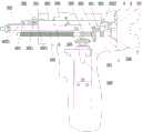
图1:本发明实施例的在初始状态下的内部结构主视图;Fig. 1: the front view of the internal structure in the initial state of the embodiment of the present invention;
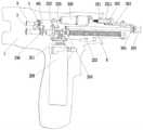
图2:本发明实施例的在失效模式下的内部结构主视图;Fig. 2: the front view of the internal structure in the failure mode of the embodiment of the present invention;
图3:本发明实施例的在失效模式下的内部结构示意图;Figure 3: a schematic diagram of the internal structure of an embodiment of the present invention in failure mode;
图4:图3中A部分的放大示意图;Figure 4: An enlarged schematic view of part A in Figure 3;
图5:本发明实施例的在初始状态下的另一侧的内部结构示意图;Figure 5: a schematic diagram of the internal structure of the other side in the initial state of the embodiment of the present invention;
图6:本发明实施例的在初始状态下的内部结构主视图;Fig. 6: the front view of the internal structure in the initial state of the embodiment of the present invention;
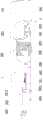
图7:本发明实施例的在失效模式下的部分结构俯视图。Fig. 7: A top view of a partial structure of an embodiment of the present invention in a failure mode.
具体实施方式Detailed ways
以下将结合附图所示的具体实施方式对本发明进行详细描述。但这些实施方式并不限于本发明,本领域的普通技术人员根据这些实施方式所做出的结构、方法、或功能上的变换均包含在本发明的保护范围内。The present invention will be described in detail below in conjunction with specific embodiments shown in the accompanying drawings. However, these embodiments are not limited to the present invention, and structural, method, or functional changes made by those skilled in the art according to these embodiments are included within the protection scope of the present invention.
在方案的描述中,需要说明的是,术语“中心”、“上”、“下”、“左”、“右”、“前”、“后”、“竖直”、“水平”、“内”、“外”、“近端”、“远端”等指示的方位或位置关系为基于附图所示的方位或位置关系,仅是为了便于描述和简化描述,而不是指示或暗示所指的装置或元件必须具有特定的方位、以特定的方位构造和操作,因此不能理解为对本发明的限制。此外,术语“第一”、“第二”、“第三”仅用于描述目的,而不能理解为指示或暗示相对重要性。并且,在方案的描述中,以操作人员为参照,靠近操作者的方向为近端,远离操作者的方向为远端。In the description of the scheme, it should be noted that the terms "center", "upper", "lower", "left", "right", "front", "rear", "vertical", "horizontal", " The orientations or positional relationships indicated by "inner", "outer", "near end" and "far end" are based on the orientation or positional relationship shown in the drawings, and are only for the convenience and simplification of description, not to indicate or imply It should not be construed as limiting the invention that a device or element must have a particular orientation, be constructed, and operate in a particular orientation. In addition, the terms "first", "second", and "third" are used for descriptive purposes only, and should not be construed as indicating or implying relative importance. Moreover, in the description of the solution, with the operator as a reference, the direction close to the operator is the proximal end, and the direction away from the operator is the distal end.
如图1至图7所示,本发明揭示了一种可在电动模式失效状况下手动操作的吻合器,包括壳体1,设置于所述壳体1前端的执行器,内置于所述壳体1的用于驱动所述执行器闭合、吻合的击发控制部以及用于驱动所述执行器摆动的摆动控制部,所述击发控制部包括第一驱动电机200和齿轮组,所述齿轮组包括设置于所述第一驱动电机200的电机轴上的主动齿轮201,以及与所述主动齿轮201相啮合并传递动力至所述执行器的从动齿轮202,所述摆动控制部包括第二驱动电机300和传动组件,所述传动组件包括螺接于所述第二驱动电机300的电机轴上的驱动块301,以及通过插接件302来接受所述驱动块301的轴向驱动力并传输至所述执行器的驱动杆303,包括第一手动构件5和连接块4,所述连接块4的近侧与所述第一手动构件5配接并被其驱动产生径向位移,所述连接块4的远侧分别设置有与之同步进行径向位移的第一限位件401和第二限位件402,所述第一限位件401通过径向位移解除对所述从动齿轮202的轴向限位,使得所述从动齿轮202可受力产生轴向位移来与所述主动齿轮201脱离,从而切断所述第一驱动电机200与所述执行器之间的动力传输;与此同时,所述第二限位件402通过径向位移驱动所述插接件302同步径向移动来使得所述驱动块301与所驱动杆303脱离,从而切断所述第二驱动电机300与所述执行器之间的动力传输。As shown in Figures 1 to 7, the present invention discloses a stapler that can be manually operated under the failure of the electric mode, including a
本方案中的所述执行器包括钳口、钉仓座、抵钉座、转向拉片、刀片、执行套管等用于完成切割、吻合动作的部件,此为现有技术,不是本发明的重点,此处不做赘述。The actuator in this solution includes the jaws, the staple cartridge seat, the nail abutment seat, the steering pull piece, the blade, the execution sleeve and other components used to complete the cutting and anastomotic actions. This is the prior art, not the invention. The key point is not to repeat them here.
如图3、图4所示,所述第一手动构件5嵌设于端盖101内,其近端为手动驱动其进行自转的驱动部,其远端面上偏心设置有一插杆501,所述插杆501与所述连接块4的近侧插接,将所述第一手动构件5的旋转运动转变成所述连接块4的径向移动。所述第一手动构件5优选为可旋转的柱状,并不外凸于所述端盖101,所述端盖101与壳体1之间的空间用于设置电池,在电池正常状态下,所述第一手动构件5由电池遮挡,来避免手动误触。所述第一手动构件5嵌设于端盖101内来保持位置的相对固定,不会影响吻合器在正常状态下的使用。所述驱动部为所述第一手动构件5的远端面上形成的凹部,所述凹部的内壁为非圆形结构,优选为六边形,来便于插接工具行旋转。在其他可行的实施例中,所述第一手动构件5也可以采用其他可行的运动方式来驱动所述连接块4进行径向移动,例如在所述端盖101上设置竖向滑槽来使得第一手动构件5可以直接通过径向移动来带动所述连接块4同步径向移动。As shown in Figures 3 and 4, the first
所述击发控制部还包括丝杆203和移动构件204,所述移动构件204螺接于所述丝杆203的螺纹部,所述移动构件204与主轴6固接,所述丝杆203通过旋转驱动所述移动构件204带动所述主轴6做轴向移动,以驱动所述主轴6控制执行器进行闭合和进行吻合操作。所述从动齿轮202可移动地套设于所述丝杆203上,其轴心通过花键带动所述丝杆203同步旋转。The firing control part also includes a
进一步的,所述丝杆203上套设有与所述从动齿轮202的前端面抵接的弹簧205,所述弹簧205始终对所述从动齿轮202产生驱动所述从动齿轮202向所述丝杆203的尾端做轴向移动的驱动力。在优选实施例中,所述弹簧205具有预缩量,使得所述弹簧205的弹力可以始终对所述从动齿轮202施加驱动力驱动其向所述丝杆203的尾端移动。在其他可行的实施例中,所述弹簧205也可以替换为拉簧,设置于所述从动齿轮202的后端面,来对所述从动齿轮202施加向所述丝杆203的尾端移动的拉力。Further, the
如图1、图2所示,所述第一限位件401的顶端与所述连接块4固接所述丝杆203的尾端设置有固定块206,在初始状态下,所述第一限位件401的底部卡设于所述从动齿轮202的后端面和所述固定块206的前端面之间,以限定所述从动齿轮202的轴向位置,使得所述从动齿轮202与主动齿轮201始终保持啮合;在第二状态下,所述第一限位件401做径向移动以致其底部与所述从动齿轮202和固定块206分离,同时所述从动齿轮202被所述弹簧205驱动做轴向移动与所述主动齿轮201分离。在优选实施例中,所述第一限位件401的底部与所述丝杆203的外轮廓相适配,使得所述第一限位件401与所述丝杆203相贴合,保证所述第一限位件401在正常使用状态下的稳定性。As shown in Fig. 1 and Fig. 2, the top end of the first limiting
进一步的,所述端盖101上嵌设有第二手动构件7,所述第二手动构件7与所述丝杆203尾端固接,并可通过自转来带动所述丝杆203同步旋转。所述第二手动构件7优选为杆状结构,所述第二手动构件7的近端端面内凹形成便于插接工具的凹部,来进行旋转操作。Further, a second
所述第一手动构件5和第二手动构件7的设置使得本方案中的吻合器在进行手术的过程中,如果突然发生了电池电量不足或第一驱动电机200故障导致所述击发控制部的电动模式失效这样的紧急状况时,可以通过第一手动构件5来用手动模式替代电动模式,继续通过手动模式进行手动操作来完成手术。The setting of the first
具体的工作原理为:首先,转动所述第一手动构件5,通过所述第一手动构件5的旋转来驱动所述连接块4做径向移动,使得所述连接块4带动第一限位件401同步做径向移动,来解除对所述从动齿轮202在轴线方向上的限位,使得所述从动齿轮202由弹簧205驱动向所述丝杆203的尾端移动来与所述主动齿轮201分离,断开所述第一驱动电机200对所述丝杆203的动力传输。然后,转动所述第二手动构件7,来驱动所述丝杆203继续进行转动,对所述执行器进行动力传输,使得执行器继续闭合,对组织进行吻合,保证手术的顺利进行,避免二次手术的重复动作,保证手术的完成率。在本方案中,电池容置于所述端盖101和壳体1之间,当失效时,需要先去除电池,再通过与所述第一手动构件5、第二手动构件7相匹配的连接件来连接转动,所述连接件可为任意可与所述第一手动构件5、第二手动构件7固接并便于手动操作的部件,这不是本方案的重点,此处不做赘述。The specific working principle is: first, rotate the first
所述摆动控制部如图、图2、图3和图5所示,所述驱动块301和驱动杆303的连接处设置有通孔,所述插接件302的顶部卡设于所述驱动块301的顶部凹槽3011内,所述插接件302的杆部插设于所述通孔内以连接所述驱动块301和驱动杆303,所述插接件302的侧部与所述第二限位件402相连接。As shown in Figures, Figures 2, 3 and 5 of the swing control part, a through hole is provided at the connection between the
具体的,所述插接件302的侧部底端具有一外凸的卡脚3021,所述第二限位件402具有一与所述驱动杆303相平行的条形卡槽4021,所述卡脚3021滑动卡设于所述条形卡槽4021内,使得所述插接件302可相对所述第二限位件402做轴向移动。同时,所述第二限位件402与所述插接件302相连接的结构,使得所述第二限位件402始终对所述插接件302起到径向方向上的限位,并可通过径向移动所述插接件302来控制所述驱动块301与驱动杆303之间的连接,进而控制所述第二驱动电机300与所述执行器之间的传动连接。Specifically, the side bottom end of the
所述摆动控制部控制执行件进行摆动的工作原理为:所述驱动杆303的远端为勾状,并与一滑动设置于所述主轴6上的连接环304卡接,并进一步通过所述连接环304与一固接于所述连接环304侧部的传动杆305进行传动连接,所述第二驱动电机300通过旋转其电机轴来驱动所述驱动块301做轴向移动,所述驱动块301进而驱动所述驱动杆303、传动杆305同步轴向移动来控制所述执行器产生摆动来移动至手术部位。The working principle of the swing control unit controlling the swing of the actuator is as follows: the distal end of the driving
在手术过程中,执行器通常需要进行摆动来与手术部位进行精准匹配,当发生电池电量不足等原因导致第二驱动电机300失效时,需要回正所述执行器来安全退出,因此,需要断开所述第二驱动电机300与所述执行器之间的传动连接。During the operation, the actuator usually needs to be oscillated to precisely match the surgical site. When the
具体的如图1-图7所示,所述第二限位件402为长条形延伸板,来连接所述连接块4与所述插接件302。所述第二限位件402的近端设置有倾斜延伸的驱动腰型孔4022,所述连接块4的侧壁固设有驱动销403,所述驱动销403滑动卡设于所述驱动腰型孔4022内,所述驱动销403跟随所述连接块4同步做径向移动,并通过径向移动来驱动所述第二限位件402同步做径向移动。所述驱动腰型孔4022优选为向所述第二限位件402的尾端倾斜45°。Specifically as shown in FIGS. 1-7 , the second limiting
为了保证所述第二限位件402的远端与其近端进行同步移动的一致性,所述第二限位件402上还设置有至少一个与所述驱动腰型孔4022垂直的从动腰型孔4023,所述从动腰型孔4023内滑动卡设有定位销404,所述定位销404固设于壳体1上。在图示实施例中,所述第二限位件402上设置有两个所述从动腰型孔4023,所述从动腰型孔4023与所述驱动腰型孔4022垂直的结构使得所述连接块4可驱动第二限位件402整体同步做径向移动。In order to ensure the consistency of the synchronous movement of the distal end of the second limiting
本发明通过设置第一手动构件5来通过旋转驱动所述连接块4做径向移动,所述连接块4带动第一限位件401、第二限位件402同步做径向移动,来同时解除第一驱动电机200、第二驱动电机300与执行器之间的动力传输,使得在失效模式下,执行器既可以回正进行安全退出,又可以通过旋转第二手动构件7来替代第一驱动电机200给执行器进行动力传输,继续完成对组织的吻合,保证手术的顺利进行,且结构简洁,制造成本低,利于推广使用。The present invention sets the first
应当理解,虽然本说明书按照实施方式加以描述,但并非每个实施方式仅包含一个独立的技术方案,说明书的这种叙述方式仅仅是为清楚起见,本领域技术人员应当将说明书作为一个整体,各实施方式中的技术方案也可以经适当组合,形成本领域技术人员可以理解的其他实施方式。It should be understood that although this description is described according to implementation modes, not each implementation mode only contains an independent technical solution, and this description in the description is only for clarity, and those skilled in the art should take the description as a whole, and each The technical solutions in the embodiments can also be properly combined to form other embodiments that can be understood by those skilled in the art.
上文所列出的一系列的详细说明仅仅是针对本发明的可行性实施方式的具体说明,它们并非用以限制本发明的保护范围,凡未脱离本发明技艺精神所作的等效实施方式或变更均应包含在本发明的保护范围之内。The series of detailed descriptions listed above are only specific descriptions for feasible implementations of the present invention, and they are not intended to limit the protection scope of the present invention. Any equivalent implementation or implementation that does not depart from the technical spirit of the present invention All changes should be included within the protection scope of the present invention.
Claims (8)
Translated fromChinesePriority Applications (3)
| Application Number | Priority Date | Filing Date | Title |
|---|---|---|---|
| CN202211452627.1ACN115644969B (en) | 2022-11-21 | 2022-11-21 | Stapler manually operable in a power mode failure condition |
| EP23893394.9AEP4623839A1 (en) | 2022-11-21 | 2023-09-21 | Stapler available for manual operation upon failure of electric mode |
| PCT/CN2023/120224WO2024109301A1 (en) | 2022-11-21 | 2023-09-21 | Stapler available for manual operation upon failure of electric mode |
Applications Claiming Priority (1)
| Application Number | Priority Date | Filing Date | Title |
|---|---|---|---|
| CN202211452627.1ACN115644969B (en) | 2022-11-21 | 2022-11-21 | Stapler manually operable in a power mode failure condition |
Publications (2)
| Publication Number | Publication Date |
|---|---|
| CN115644969A CN115644969A (en) | 2023-01-31 |
| CN115644969Btrue CN115644969B (en) | 2023-03-21 |
Family
ID=85019378
Family Applications (1)
| Application Number | Title | Priority Date | Filing Date |
|---|---|---|---|
| CN202211452627.1AActiveCN115644969B (en) | 2022-11-21 | 2022-11-21 | Stapler manually operable in a power mode failure condition |
Country Status (3)
| Country | Link |
|---|---|
| EP (1) | EP4623839A1 (en) |
| CN (1) | CN115644969B (en) |
| WO (1) | WO2024109301A1 (en) |
Families Citing this family (7)
| Publication number | Priority date | Publication date | Assignee | Title |
|---|---|---|---|---|
| CN115644969B (en)* | 2022-11-21 | 2023-03-21 | 以诺康医疗科技(苏州)有限公司 | Stapler manually operable in a power mode failure condition |
| WO2024109712A1 (en)* | 2022-11-23 | 2024-05-30 | 天臣国际医疗科技股份有限公司 | Reset device and surgical operation instrument |
| CN116269581A (en)* | 2023-03-27 | 2023-06-23 | 北京派尔特医疗科技股份有限公司 | Electric anastomat |
| CN117694952B (en)* | 2024-02-01 | 2024-04-16 | 以诺康医疗科技(苏州)有限公司 | Emergency switching device, electric stapler and medical equipment |
| CN119326464B (en)* | 2024-08-08 | 2025-08-15 | 江苏孜航精密五金有限公司 | Manual reset mechanism for swing angle and electric endoscope anastomat thereof |
| CN119302712A (en)* | 2024-11-14 | 2025-01-14 | 长沙乐普外科医疗器械有限公司 | A jaw disengagement device for a trigger of a minimally invasive energy instrument and a method of using the same |
| CN119908786A (en)* | 2025-01-24 | 2025-05-02 | 宝玛医疗科技(无锡)有限公司 | A stapler and a supporting structure of a stapler power output mechanism |
Citations (6)
| Publication number | Priority date | Publication date | Assignee | Title |
|---|---|---|---|---|
| EP2078500A1 (en)* | 2008-01-10 | 2009-07-15 | Ethicon Endo-Surgery, Inc. | Surgical stapling instrument with a firing member return mechanism |
| CN106821441A (en)* | 2017-02-28 | 2017-06-13 | 苏州法兰克曼医疗器械有限公司 | A kind of electronic stapler and its percussion backoff control method |
| CN109199490A (en)* | 2017-07-03 | 2019-01-15 | 江苏风和医疗器材股份有限公司 | A kind of manual overvide of electric transmissio mechanism |
| CN212382685U (en)* | 2020-06-11 | 2021-01-22 | 瑞贝医疗器械(常州)有限公司 | Manual percussion disconnect-type electronic anastomat |
| CN215079029U (en)* | 2021-03-31 | 2021-12-10 | 天津瑞奇外科器械股份有限公司 | Electric surgical handheld equipment and surgical instrument |
| CN114795344A (en)* | 2021-01-28 | 2022-07-29 | 江苏特普优微创医疗科技有限公司 | Transmission structure of electric endoscope linear type cutting anastomat |
Family Cites Families (7)
| Publication number | Priority date | Publication date | Assignee | Title |
|---|---|---|---|---|
| US20090090763A1 (en)* | 2007-10-05 | 2009-04-09 | Tyco Healthcare Group Lp | Powered surgical stapling device |
| US8608045B2 (en)* | 2008-10-10 | 2013-12-17 | Ethicon Endo-Sugery, Inc. | Powered surgical cutting and stapling apparatus with manually retractable firing system |
| US10709495B2 (en)* | 2015-11-13 | 2020-07-14 | Ethicon Llc | Dual step bailout for motorized RF device |
| CN112472175B (en)* | 2019-09-11 | 2022-02-18 | 江苏风和医疗器材股份有限公司 | Surgical instrument |
| CN213665481U (en)* | 2020-04-01 | 2021-07-13 | 盈甲医疗器械制造(上海)有限公司 | Electric bending failure remediation device and electric anastomat thereof |
| CN113796906B (en) | 2021-09-26 | 2025-03-11 | 赛诺微医疗科技(浙江)有限公司 | Emergency release device, electric stapler, medical equipment |
| CN115644969B (en)* | 2022-11-21 | 2023-03-21 | 以诺康医疗科技(苏州)有限公司 | Stapler manually operable in a power mode failure condition |
- 2022
- 2022-11-21CNCN202211452627.1Apatent/CN115644969B/enactiveActive
- 2023
- 2023-09-21WOPCT/CN2023/120224patent/WO2024109301A1/ennot_activeCeased
- 2023-09-21EPEP23893394.9Apatent/EP4623839A1/enactivePending
Patent Citations (6)
| Publication number | Priority date | Publication date | Assignee | Title |
|---|---|---|---|---|
| EP2078500A1 (en)* | 2008-01-10 | 2009-07-15 | Ethicon Endo-Surgery, Inc. | Surgical stapling instrument with a firing member return mechanism |
| CN106821441A (en)* | 2017-02-28 | 2017-06-13 | 苏州法兰克曼医疗器械有限公司 | A kind of electronic stapler and its percussion backoff control method |
| CN109199490A (en)* | 2017-07-03 | 2019-01-15 | 江苏风和医疗器材股份有限公司 | A kind of manual overvide of electric transmissio mechanism |
| CN212382685U (en)* | 2020-06-11 | 2021-01-22 | 瑞贝医疗器械(常州)有限公司 | Manual percussion disconnect-type electronic anastomat |
| CN114795344A (en)* | 2021-01-28 | 2022-07-29 | 江苏特普优微创医疗科技有限公司 | Transmission structure of electric endoscope linear type cutting anastomat |
| CN215079029U (en)* | 2021-03-31 | 2021-12-10 | 天津瑞奇外科器械股份有限公司 | Electric surgical handheld equipment and surgical instrument |
Also Published As
| Publication number | Publication date |
|---|---|
| CN115644969A (en) | 2023-01-31 |
| EP4623839A1 (en) | 2025-10-01 |
| WO2024109301A1 (en) | 2024-05-30 |
Similar Documents
| Publication | Publication Date | Title |
|---|---|---|
| CN115644969B (en) | Stapler manually operable in a power mode failure condition | |
| JP6445827B2 (en) | Tip assembly for surgical instruments | |
| RU2546958C2 (en) | Improving power-driven surgical suturing instrument | |
| CN103142278B (en) | Circular tube-type anastomat | |
| EP1847225A1 (en) | A rotatable stapling head of a surgical stapler | |
| CN111466974B (en) | Surgical instrument and linear stapler | |
| CN103800043A (en) | Circular stapler mechanical lock | |
| US11534172B2 (en) | Electromechanical surgical stapler including trocar assembly release mechanism | |
| CN103654897A (en) | Surgical fastener applying apparatus including fluid-activated firing mechanism | |
| CN105455864B (en) | The drive device and surgical operating instrument of surgical operating instrument | |
| CN115568897B (en) | Anastomat with switch locking linkage mechanism | |
| CN203029312U (en) | Round tube shaped anastomat | |
| WO2024109714A1 (en) | Emergency apparatus and surgical instrument | |
| CN114652382A (en) | Electrically driven prepuce anastomat | |
| WO2023104044A1 (en) | Jaw driving device for surgical instrument and surgical instrument | |
| CN115137426A (en) | Motorized surgical instrument | |
| CN213189866U (en) | Electric pushing device for triggering anastomat | |
| CN218870377U (en) | Reset devices and surgical instruments | |
| CN211911740U (en) | Knob assembly and circumcision stapler having the same | |
| CN111466975B (en) | Surgical instrument and linear stapler | |
| CN220175171U (en) | Surgical instrument | |
| CN117694952A (en) | Emergency switching devices, electric staplers and medical equipment | |
| CN117731350A (en) | Anastomat with false locking prevention function | |
| CN106308890B (en) | Disposable prepuce cutting anastomat | |
| CN204839621U (en) | Tubular type anastomat and integral type transmission lead screw thereof |
Legal Events
| Date | Code | Title | Description |
|---|---|---|---|
| PB01 | Publication | ||
| PB01 | Publication | ||
| SE01 | Entry into force of request for substantive examination | ||
| SE01 | Entry into force of request for substantive examination | ||
| GR01 | Patent grant | ||
| GR01 | Patent grant | ||
| CP03 | Change of name, title or address | ||
| CP03 | Change of name, title or address | Address after:215000 Jiangsu Province, Suzhou City, Industrial Park, Xinghu Street 218, Room B2-409 Patentee after:Enkang Medical Technology (Suzhou) Co., Ltd. Country or region after:China Patentee after:Yinuokang Medical Technology (Hefei) Co.,Ltd. Address before:215000 Jiangsu Province, Suzhou City, Industrial Park, Xinghu Street 218, Room B2-409 Patentee before:INNOLCON MEDICAL TECHNOLOGY (SUZHOU) Co.,Ltd. Country or region before:China Patentee before:Yinuokang Medical Technology (Hefei) Co.,Ltd. |