CN115624359A - Electric suturing device - Google Patents
Electric suturing deviceDownload PDFInfo
- Publication number
- CN115624359A CN115624359ACN202211652020.8ACN202211652020ACN115624359ACN 115624359 ACN115624359 ACN 115624359ACN 202211652020 ACN202211652020 ACN 202211652020ACN 115624359 ACN115624359 ACN 115624359A
- Authority
- CN
- China
- Prior art keywords
- bending
- gear
- driving mechanism
- working end
- assembly
- Prior art date
- Legal status (The legal status is an assumption and is not a legal conclusion. Google has not performed a legal analysis and makes no representation as to the accuracy of the status listed.)
- Pending
Links
Images


Classifications
- A—HUMAN NECESSITIES
- A61—MEDICAL OR VETERINARY SCIENCE; HYGIENE
- A61B—DIAGNOSIS; SURGERY; IDENTIFICATION
- A61B17/00—Surgical instruments, devices or methods
- A61B17/04—Surgical instruments, devices or methods for suturing wounds; Holders or packages for needles or suture materials
- A61B17/0469—Suturing instruments for use in minimally invasive surgery, e.g. endoscopic surgery
- A—HUMAN NECESSITIES
- A61—MEDICAL OR VETERINARY SCIENCE; HYGIENE
- A61B—DIAGNOSIS; SURGERY; IDENTIFICATION
- A61B17/00—Surgical instruments, devices or methods
- A61B17/04—Surgical instruments, devices or methods for suturing wounds; Holders or packages for needles or suture materials
- A61B17/0491—Sewing machines for surgery
Landscapes
- Health & Medical Sciences (AREA)
- Life Sciences & Earth Sciences (AREA)
- Surgery (AREA)
- Heart & Thoracic Surgery (AREA)
- Engineering & Computer Science (AREA)
- Biomedical Technology (AREA)
- Nuclear Medicine, Radiotherapy & Molecular Imaging (AREA)
- Medical Informatics (AREA)
- Molecular Biology (AREA)
- Animal Behavior & Ethology (AREA)
- General Health & Medical Sciences (AREA)
- Public Health (AREA)
- Veterinary Medicine (AREA)
- Surgical Instruments (AREA)
- Transmission Devices (AREA)
Abstract
Description
Translated fromChinese技术领域technical field
本发明涉及医疗器械领域,特别涉及一种电动缝合装置。The invention relates to the field of medical equipment, in particular to an electric suturing device.
背景技术Background technique
腹腔镜手术是一门新发展起来的微创方法,是未来手术方法发展的必然趋势。随着工业制造技术的突飞猛进,相关学科的融合为开展新技术、新方法奠定了坚定的基础,加上医生越来越娴熟的操作,使得许多过去的开放性手术已被腔内手术取而代之,大大增加了手术选择的机会。腹腔镜手术传统方法是首先插入一个叫做"trocar"的管道状工作通道,以后一切操作均通过这个管道进行;用特制的加长手术器械在视频监视下完成与开放手术同样的步骤,达到同样的手术效果。近年来,具有创伤小、恢复快、痛苦轻、治愈率高等优点的微创外科发展迅速,腹腔镜作为微创外科的代表,在外科领域被广泛应用,涉及许多病种和手术,受到患者欢迎,而且随着科学技术的不断进步,手术器械不断改进创新,腹腔镜的施展空间将会越来越大。Laparoscopic surgery is a newly developed minimally invasive method, and it is an inevitable trend in the development of future surgical methods. With the rapid development of industrial manufacturing technology, the integration of related disciplines has laid a solid foundation for the development of new technologies and methods. Coupled with the increasingly skilled operation of doctors, many open surgeries in the past have been replaced by endovascular surgeries. Increased chances of surgical options. The traditional method of laparoscopic surgery is to first insert a tube-shaped working channel called "trocar", and then all operations will be performed through this tube; use special lengthened surgical instruments to complete the same steps as open surgery under video monitoring to achieve the same surgery Effect. In recent years, minimally invasive surgery, which has the advantages of less trauma, faster recovery, less pain, and high cure rate, has developed rapidly. As a representative of minimally invasive surgery, laparoscopy has been widely used in the field of surgery, involving many diseases and operations, and is welcomed by patients , and with the continuous advancement of science and technology, and the continuous improvement and innovation of surgical instruments, the space for laparoscopy will become larger and larger.
由于腹腔或者胸腔内空间的限制,微创手术器械必然是比较小且比较长的,才可实现精确的操作。在微创腹腔手术内操作难度相对大的无疑是缝合。过去,通过内窥镜外科手术对身体器官或组织的缝合是通过使用尖利的金属缝合针实现的,所述缝合针的一端系有一定长度的缝合材料,外科医生操作缝合针刺透并穿过身体组织,将缝合材料拖过身体组织,一旦缝合材料被拖过身体组织,外科医生就对缝合材料打个结,缝合材料的结点允许外科医生调节缝合材料的张力以适应正在被缝合的特定组织并且控制组织的近似 值、闭合、联结或其它情况。对外科医生来说控制张力的能力是极其重要的,而与正在进行的外科手术程序的类型无关。在传统的缝合中需要用双手协调操作缝合针和持针器械在有限的空间内连续缝合,许多外科医生发现此操作是极其困难的,并且缝合针的裸露也容易导致意外发生,比如会刺破患者其他器官或伤到外科医生、护士。Due to the limitation of the space in the abdominal cavity or the thoracic cavity, minimally invasive surgical instruments must be relatively small and relatively long to achieve precise operations. Suture is undoubtedly the most difficult operation in minimally invasive abdominal surgery. In the past, suturing body organs or tissues through endoscopic surgery was accomplished by using a sharp metal suture needle with a length of suture material tied to one end, which the surgeon manipulates to pierce and pass through Body tissue, to draw the suture material through the body tissue. Once the suture material has been drawn through the body tissue, the surgeon ties a knot to the suture material. The knot of the suture material allows the surgeon to adjust the tension of the suture material to suit the specific area being sutured. Organize and control approximations, closures, joins, or other conditions of organization. The ability to control tension is extremely important to the surgeon regardless of the type of surgical procedure being performed. In traditional suturing, it is necessary to use both hands to coordinate the operation of the suture needle and the needle-holding instrument to suture continuously in a limited space. Many surgeons find this operation extremely difficult, and the exposed suture needle is also prone to accidents, such as puncture. Other organs of the patient or injuries to surgeons and nurses.
随着技术的发展,半手动缝合器已经在手术中使用,在操作半手动缝合器进行手术时,通过握动击发扳机,一个循环即扳机完全握下与完全打开复位实现出针扎入缝合组织,再次握动击发扳机实现缝合针完全穿透组织、缝针归位,如没有归位,则需要多次重复握动扳机,因此一台手术需要医生连续数次手动握动击发扳机,操作费力且需要较长的缝合时间。With the development of technology, semi-manual staplers have been used in surgery. When operating a semi-manual stapler for surgery, by holding the firing trigger, one cycle, that is, the trigger is completely held down and fully opened to reset, so that the needle can be inserted into the sutured tissue. , hold the firing trigger again to realize that the suture needle completely penetrates the tissue and the needle returns to its original position. If it does not return to its original position, it is necessary to repeatedly hold the trigger many times. Therefore, one operation requires the doctor to manually hold the firing trigger several times in a row, and the operation is laborious. And need longer sewing time.
发明内容Contents of the invention
本发明要解决的是现有技术中缝合器操作费力的技术问题。What the present invention aims to solve is the technical problem of laborious operation of the stapler in the prior art.
为解决上述技术问题,本发明提供的技术方案如下:In order to solve the problems of the technologies described above, the technical solutions provided by the invention are as follows:
一种电动缝合装置,包括:工作端组件、主驱动机构、弯转驱动机构和旋转驱动机构;工作端组件包括缝合组件和弯转连接管,其中,主驱动机构用于驱动针线部件往复旋转对缝合组织进行缝合,弯转驱动机构用于驱动工作端组件左右摆动以调整工作端组件相对缝合组织的位置,旋转驱动机构用于驱动工作端组件的缝合组件围绕工作端轴线实现360度旋转,从而调整针线部件相对缝合组织的入针点位置。An electric suturing device, comprising: a working end assembly, a main driving mechanism, a bending driving mechanism and a rotating driving mechanism; The suture tissue is sutured, the bending drive mechanism is used to drive the working end assembly to swing left and right to adjust the position of the working end assembly relative to the suture tissue, and the rotating drive mechanism is used to drive the suturing assembly of the working end assembly to rotate 360 degrees around the axis of the working end, thereby Adjust the position of the needle entry point of the needle and thread parts relative to the suture tissue.
本发明通过设置主驱动机构、弯转驱动机构和旋转驱动机构,可以方便医生调节缝合组件的位置和进行缝合操作,从而可以提高缝合效率,缩短手术时间。By setting the main driving mechanism, the bending driving mechanism and the rotating driving mechanism, the present invention can facilitate the doctor to adjust the position of the suturing assembly and perform the suturing operation, thereby improving the suturing efficiency and shortening the operation time.
进一步地,所述电动缝合装置还包括支撑组件,支撑组件包括:主骨架、副骨架、右外壳、左外壳、手柄;动力电源可拆卸地安装于手柄内,主骨架和副骨架用于固定安装主驱动机构、弯转驱动机构和旋转驱动机构。Further, the electric suturing device also includes a support assembly, and the support assembly includes: a main frame, a sub-frame, a right shell, a left shell, and a handle; the power supply is detachably installed in the handle, and the main frame and the sub-frame are used for fixed installation Main drive mechanism, bending drive mechanism and rotary drive mechanism.
进一步地,电动缝合装置还包括延长管,延长管的远端连接工作端组件,延长管用于穿过手术通道,把工作端组件推送至需要缝合的部位。Further, the electric suturing device also includes an extension tube, the distal end of the extension tube is connected to the working end assembly, and the extension tube is used to pass through the surgical channel to push the working end assembly to the site to be sutured.
进一步地,主驱动机构包括:主驱动电机、偏心轮、缓冲器、延长杆、柔性轴;主驱动电机驱动偏心轮旋转带动缓冲器做直线往复运动,缓冲器的远端与延长杆的近端连接,延长杆的远端与柔性轴的近端固定连接,柔性轴的远端与工作端组件连接。Further, the main drive mechanism includes: a main drive motor, an eccentric wheel, a buffer, an extension rod, and a flexible shaft; the main drive motor drives the eccentric wheel to rotate to drive the buffer to perform linear reciprocating motion, and the far end of the buffer and the proximal end of the extension rod connection, the distal end of the extension rod is fixedly connected with the proximal end of the flexible shaft, and the distal end of the flexible shaft is connected with the working end assembly.
进一步地,工作端组件包括缝合组件和弯转连接管,其中,缝合部件包括:齿条部件、齿轮部件、连杆部件、基座;其中,齿条部件与齿轮部件通过齿形咬合,柔性轴与齿条部件的一端固定连接;连杆部件设有销轴与齿轮部件设有的腰型孔铰接配合;连杆部件设有顶针杆基座装入基座的弧形槽内,从而形成反四边形曲柄滑块机构。Further, the working end assembly includes a suture assembly and a curved connecting pipe, wherein the suture component includes: a rack component, a gear component, a connecting rod component, and a base; wherein, the rack component and the gear component engage through teeth, and the flexible shaft It is fixedly connected with one end of the rack part; the connecting rod part is provided with a pin shaft and is hingedly matched with the waist hole provided by the gear part; Quadrilateral slider crank mechanism.
进一步地,主驱动机构、弯转驱动机构和旋转驱动机构可独立操作,且三者操作时互不影响。Further, the main driving mechanism, the turning driving mechanism and the rotating driving mechanism can operate independently, and the three do not affect each other during operation.
进一步地,弯转驱动机构包括:弯转驱动电机、弯转电机齿轮箱部件、弯转连杆、弯转拉片和弯转关节;弯转电机齿轮箱部件包括传动螺杆和连接块,弯转驱动电机驱动传动螺杆旋转带动连接块往复直线运动,连接块与弯转连杆连接,连接块往复直线运动带动弯转连杆连接的弯转拉片推拉运动,从而带动工作端组件围绕弯转关节设有的两处连接销弯转。Further, the turning drive mechanism includes: a turning drive motor, a turning motor gearbox part, a turning connecting rod, a turning pull piece and a turning joint; the turning motor gearbox part includes a transmission screw and a connecting block, and the turning The drive motor drives the transmission screw to rotate to drive the connecting block to reciprocate and linearly move. The connecting block is connected to the bending connecting rod. The reciprocating linear motion of the connecting block drives the pushing and pulling movement of the bending pull piece connected to the bending connecting rod, thereby driving the working end components to revolve around the bending joint. Two connecting pins provided with bend.
进一步地,旋转驱动机构包括中心齿轮,中心齿轮的中心设有D型孔,延长杆穿过中心齿轮中心的D型孔;所述旋转驱动机构还包括电动驱动结构和/或手动驱动结构,其中,电动驱动结构包括:减速马达、电机齿轮;电机齿轮与中心齿轮咬合,减速马达旋转带动电机齿轮旋转,电机齿轮带动中心齿轮反向旋转,中心齿轮带动延长杆随着反向旋转,并通过柔性轴传递旋转带动工作端组件的缝合组件进行旋转运动;手动驱动结构包括:旋转头、惰性齿轮、驱动齿轮,旋转头设有内齿轮,内齿轮、惰性齿轮、驱动齿轮、中心齿轮互相咬合,手动转动旋转头,通过内齿轮、惰性齿轮、驱动齿轮、中心齿轮带动延长杆旋转,并通过柔性轴传递旋转从而带动工作端组件的缝合组件进行旋转运动。Further, the rotary drive mechanism includes a central gear, and the center of the central gear is provided with a D-shaped hole, and the extension rod passes through the D-shaped hole in the center of the central gear; the rotary drive mechanism also includes an electric drive structure and/or a manual drive structure, wherein , the electric drive structure includes: deceleration motor, motor gear; the motor gear meshes with the central gear, the deceleration motor rotates to drive the motor gear to rotate, the motor gear drives the central gear to rotate in the opposite direction, the central gear drives the extension rod to rotate in the reverse direction, and through the flexible The shaft transmits the rotation to drive the sewing assembly of the working end assembly to rotate; the manual drive structure includes: a rotating head, an idler gear, and a driving gear. Rotate the rotating head, drive the extension rod to rotate through the internal gear, idler gear, driving gear, and central gear, and transmit the rotation through the flexible shaft to drive the suture assembly of the working end assembly to rotate.
进一步地,电动缝合装置还包括操控电控组件,操控电控组件包括按键模块和电路模块;其中,按键模块包括:主按键、左按键、右按键;其中,主按键用于控制主驱动机构和弯转驱动机构,左按键和右按键用于控制旋转驱动机构。Further, the electric sewing device also includes a control electric control assembly, and the control electric control assembly includes a button module and a circuit module; wherein, the button module includes: a main button, a left button, and a right button; wherein, the main button is used to control the main drive mechanism and The turning drive mechanism, the left button and the right button are used to control the rotation drive mechanism.
进一步地,左按键、右按键对称设计,方便操作者左右手互换操作。Furthermore, the symmetrical design of the left button and the right button is convenient for the operator to operate interchangeably with the left and right hands.
采用这样的设计后,本发明至少具有以下优点:After adopting such design, the present invention has the following advantages at least:
(1)发明通过设置主驱动机构、弯转驱动机构和旋转驱动机构,可以方便医生调节缝合组件的位置和进行缝合操作,从而可以提高缝合效率,缩短手术时间。(2)本发明的电动缝合装置操作方便,可实现单手操作,减少器械调整操作耗时,节省手术时间。(3)本发明结构简单,效果好,且成本低,易工艺实现。(1) By setting the main drive mechanism, the bending drive mechanism and the rotation drive mechanism, the invention can facilitate the doctor to adjust the position of the suture assembly and perform the suture operation, thereby improving the suture efficiency and shortening the operation time. (2) The electric suturing device of the present invention is easy to operate, can realize one-handed operation, reduces the time-consuming operation of instrument adjustment, and saves operation time. (3) The present invention has simple structure, good effect, low cost and easy technological realization.
附图说明Description of drawings
上述仅是本发明技术方案的概述,为了能够更清楚了解本发明的技术手段,以下结合附图与具体实施方式对本发明作进一步的详细说明The above is only an overview of the technical solution of the present invention. In order to better understand the technical means of the present invention, the present invention will be further described in detail below in conjunction with the accompanying drawings and specific embodiments
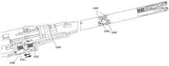
图1是本发明电动缝合装置的部件分解示意图;Fig. 1 is an exploded schematic diagram of parts of the electric suturing device of the present invention;
图2是本发明电动缝合装置的部件剖面结构示意图;Fig. 2 is a schematic diagram of the cross-sectional structure of the components of the electric suturing device of the present invention;
图3是本发明主驱动机构的结构示意图;Fig. 3 is a schematic structural view of the main drive mechanism of the present invention;
图4是本发明工作端组件的剖面示意图;Fig. 4 is a schematic cross-sectional view of the working end assembly of the present invention;
图5是本发明工作端内部结构示意图;Fig. 5 is a schematic diagram of the internal structure of the working end of the present invention;
图6是本发明工作端组件的运行原理示意图;Fig. 6 is a schematic diagram of the operating principle of the working end assembly of the present invention;
图7是本发明弯转驱动机构示意图;Fig. 7 is a schematic diagram of the turning drive mechanism of the present invention;
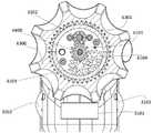
图8为本发明旋转驱动机构示意图;Fig. 8 is a schematic diagram of the rotary drive mechanism of the present invention;
图9为本发明旋转驱动机构剖面结构示意图;Fig. 9 is a schematic cross-sectional structure diagram of the rotary drive mechanism of the present invention;
附图标记,1100主骨架、1200副骨架、1300右外壳、1400左外壳、1401手柄、1500上壳、1600延长管、2000动力电源、3100按键模块、3101左按键、3102右按键、3103主按键、3200电路模块、4100主驱动电机、4200偏心轮、4300缓冲器、4400延长杆、4500柔性轴、5100弯转电机齿轮箱部件、5101传动螺杆、5102连接块、5200弯转连杆、5300弯转拉片、5400弯转关节、5500连接销、6100齿轮箱部件、6101中心齿轮、6102电机齿轮、6103惰性齿轮、6104驱动齿轮、6200减速马达、6300旋转头、6301内齿轮、7000工作端组件、7100齿条部件、7200齿轮部件、7201腰型孔、7300连杆部件、7301顶针杆基座、7302销轴、7400基座、7401弧形槽、7500弯转连接管、7600针线部件。Reference signs, 1100 main frame, 1200 sub-frame, 1300 right shell, 1400 left shell, 1401 handle, 1500 upper shell, 1600 extension tube, 2000 power supply, 3100 button module, 3101 left button, 3102 right button, 3103 main button , 3200 circuit module, 4100 main drive motor, 4200 eccentric wheel, 4300 buffer, 4400 extension rod, 4500 flexible shaft, 5100 bending motor gearbox components, 5101 transmission screw, 5102 connecting block, 5200 bending connecting rod, 5300 bending Turn pull piece, 5400 bending joint, 5500 connecting pin, 6100 gearbox components, 6101 central gear, 6102 motor gear, 6103 idler gear, 6104 driving gear, 6200 deceleration motor, 6300 rotating head, 6301 internal gear, 7000 working end assembly , 7100 rack parts, 7200 gear parts, 7201 waist hole, 7300 connecting rod parts, 7301 thimble bar base, 7302 pin shaft, 7400 base, 7401 arc groove, 7500 curved connecting pipe, 7600 needle thread parts.
具体实施方式Detailed ways
下面将结合本发明实施例中的附图,对本发明实施例中的技术方案进行清楚、完整的描述,显然,所描述的实施例仅仅是本发明一部分实施例,而不是全部的实施例。基于本发明中的实施例,本领域普通技术人员在没有作出创造性劳动前提下所获得的所有其他实施例,都属于本发明保护的范围。The technical solutions in the embodiments of the present invention will be clearly and completely described below in conjunction with the accompanying drawings in the embodiments of the present invention. Obviously, the described embodiments are only some, not all, embodiments of the present invention. Based on the embodiments of the present invention, all other embodiments obtained by persons of ordinary skill in the art without creative efforts fall within the protection scope of the present invention.
在本文中,“上”、“下”等仅用于表示相关部分之间的相对位置关系,而非限定这些相关部分的绝对位置。Herein, "upper", "lower" and the like are only used to indicate the relative positional relationship between related parts, rather than to limit the absolute positions of these related parts.
以下每个部件靠近操作者的一端定义为近端,远离操作者的一端定义为远端。该近端、远端的表达只用于使描述简单、清楚,不应该理解为对本发明的任何限定。The end of each of the following components close to the operator is defined as the proximal end, and the end far away from the operator is defined as the distal end. The expressions of proximal end and distal end are only used to make the description simple and clear, and should not be construed as any limitation to the present invention.
参见附图1-5,一种电动缝合装置,包括:工作端组件7000、主驱动机构、弯转驱动机构和旋转驱动机构;工作端组件7000包括缝合组件和弯转连接管,其中,主驱动机构用于驱动针线部件7600往复旋转对缝合组织进行缝合,弯转驱动机构用于驱动工作端组件7000左右摆动调整工作端组件7000相对缝合组织的位置,旋转驱动机构用于驱动缝合组件围绕缝合组件轴线实现360度旋转,从而调整针线部件7600相对组织缝合的入针点位置。Referring to accompanying drawings 1-5, an electric suturing device includes: a working
所述电动缝合装置还包括支撑组件,支撑组件包括:主骨架1100、副骨架1200、右外壳1300、左外壳1400、手柄1401;动力电源2000可拆卸地安装于手柄内,主骨架和副骨架用于固定安装主驱动机构、弯转驱动机构和旋转驱动机构。动力电源2000为主驱动机构、弯转驱动机构和旋转驱动机构提供电源驱动,动力电源可以快速插接至手柄1401处,主骨架1100、副骨架1200作为安装三个驱动机构的主要支撑件,用于实现对三个驱动机构的固定安装。The electric suturing device also includes a support assembly, and the support assembly includes: a
电动缝合装置还设有延长管1600,延长管1600的远端连接工作端组件7000,延长管用于穿过手术通道,把工作端组件7000推送至需要缝合的部位。The electric suturing device is also provided with an
主驱动机构包括:主驱动电机4100、偏心轮4200、缓冲器4300、延长杆4400、柔性轴4500。主驱动电机4100驱动偏心轮4200旋转带动缓冲器4300做直线往复运动,缓冲器4300的远端与延长杆4400连接,延长杆4400的远端与柔性轴4500固定连接,柔性轴4500的远端与工作端组件7000连接;主驱动机构通过柔性轴4500驱动工作端组件7000进行缝合操作。其中,缓冲部件包括:缓冲弹簧、缓冲杆、缓冲轴套;缓冲部件能够实现拉动和推动过程的缓冲。优选地,延长杆与柔性轴的固定方式包括但不限于焊接、过盈压装等。柔性轴4500是刚性很小且具有弹性可自由弯曲传动的轴,用于联接不在同一轴线和不在同一方向或有相对运动的两轴以传递旋转运动和扭矩,能把旋转运动和转矩灵活地传到任何位置。The main drive mechanism includes: a
参见附图5-6,工作端组件7000包括缝合组件和弯转连接管7500,其中缝合部件包括:齿条部件7100、齿轮部件7200、连杆部件7300、基座7400。其中,齿条部件7100与齿轮部件7200通过齿形咬合,柔性轴4500与齿条部件7100的一端固定连接。连杆部件7300设有销轴7302与齿轮部件7200设有的腰型孔7201铰接配合;连杆部件7300设有顶针杆基座7301装入基座7400的弧形槽7401内,从而形成反四边形曲柄滑块机构。通过柔性轴4500推拉齿条部件7100往复运动可联动齿轮部件7200旋转,齿轮部件7200旋转带动连杆部件7300摆动,带动顶针杆基座7301在弧形槽7401往复摆动,从而实现缝合操作。Referring to Figures 5-6, the working
主驱动机构、弯转驱动机构和旋转驱动机构可独立操作,且三者操作时互不影响。参见附图7,弯转驱动机构包括:弯转驱动电机、弯转电机齿轮箱部件5100、弯转连杆5200、弯转拉片5300和弯转关节5400。弯转驱动电机驱动弯转电机齿轮箱部件5100输出动力,弯转电机齿轮箱部件5100包括传动螺杆5101和连接块5102,弯转驱动电机驱动传动螺杆5101旋转带动连接块5102往复直线运动,连接块5102与弯转连杆5200连接,连接块5102往复运动带动弯转连杆5200连接的弯转拉片5300推拉运动,从而带动工作端组件7000围绕弯转关节5400设有的两处连接销5500弯转。柔性轴4500穿过弯转关节5400处,当工作端组件弯转时,位于中心的柔性轴4500也会随着弯转,柔性轴4500由于其固有的特性,因此弯转后也可以传动推拉力和扭转力。The main driving mechanism, the bending driving mechanism and the rotating driving mechanism can be operated independently, and the operation of the three does not affect each other. Referring to FIG. 7 , the turning drive mechanism includes: a turning driving motor, a turning
参见附图8-9,旋转驱动机构包括中心齿轮6101,中心齿轮6101的中心设有D型孔,延长杆穿过中心齿轮中心的D型孔,旋转驱动机构包括电动和/或手动驱动结构,其中电动驱动结构包括:减速马达6200、电机齿轮6102,中心齿轮6101和电机齿轮6102组成齿轮箱部件6100;工作端组件的弯转连接管7500与弯转关节铰接连接。电机齿轮与中心齿轮咬合,减速马达6200旋转带动电机齿轮旋转,电机齿轮旋转带动中心齿轮6101反向旋转,从而带动延长杆4400随着反向旋转,并通过柔性轴4500传递旋转从而带动工作端组件7000的缝合组件进行旋转运动。通过截面为D型结构的延长杆4400与中心齿轮6101中心设置的D型孔配合,可以使得主驱动机构驱动延长杆的直线往复运动和旋转驱动机构驱动延长杆的旋转运动互不影响。Referring to accompanying drawings 8-9, the rotary drive mechanism includes a
手动驱动结构包括:旋转头6300、惰性齿轮6103、驱动齿轮6104,旋转头6300设有内齿轮6301,内齿轮6301、惰性齿轮6103、驱动齿轮6104、中心齿轮6101互相咬合,手动转动旋转头6300,可以通过内齿轮6301、惰性齿轮6103、驱动齿轮6104、中心齿轮6101带动延长杆旋转,并通过柔性轴4500传递旋转从而带动工作端组件7000的缝合组件进行旋转运动。当同时设置手动和电动驱动结构时,可以实现电动旋转与手动旋转操作的任意切换。The manual driving structure includes: a rotating
参见附,1、9,进一步地,电动缝合装置还包括操控件电控组件,操控电控组件包括按键模块3100和电路模块3200。按键模块3100包括:主按键3103、左按键3101、右按键3102。其中,主按键用于控制主驱动机构和弯转驱动机构,左按键和右按键用于控制旋转驱动机构。其中左按键3101、右按键3102对称设计,方便操作者左右手互换操作器械。电路模块3200预设程序用于整体电控系统的控制,包括电机驱动,电压检测、电流检测、状态提示等。See appendix 1, 9, further, the electric suturing device also includes the electric control component of the manipulation member, and the control electric control component includes a
本领域技术人员在考虑说明书及实施例公开的发明后,将容易想到本发明的其它实施方案。本申请旨在涵盖本发明的任何变型、用途或者适应性变化,这些变型、用途或者适应性变化遵循本发明的一般性原理并包括本发明未公开的本技术领域中的公知常识或惯用技术手段。说明书和实施例仅被视为示例性的,本发明的真正范围和精神由下面的权利要求指出。Other embodiments of the invention will readily occur to those skilled in the art from consideration of the invention disclosed in the specification and examples. This application is intended to cover any modification, use or adaptation of the present invention, these modifications, uses or adaptations follow the general principles of the present invention and include common knowledge or conventional technical means in the technical field not disclosed in the present invention . The specification and examples are to be considered exemplary only, with a true scope and spirit of the invention being indicated by the following claims.
应当理解的是,本发明并不局限于上面已经描述并在附图中示出的精确结构,并且可以在不脱离其范围进行各种修改和改变。本发明的范围仅由所附的权利要求来限制。It should be understood that the present invention is not limited to the precise constructions which have been described above and shown in the accompanying drawings, and various modifications and changes may be made without departing from the scope thereof. The scope of the invention is limited only by the appended claims.
Claims (10)
Priority Applications (3)
| Application Number | Priority Date | Filing Date | Title |
|---|---|---|---|
| CN202211652020.8ACN115624359A (en) | 2022-12-22 | 2022-12-22 | Electric suturing device |
| PCT/CN2023/139974WO2024131800A1 (en) | 2022-12-22 | 2023-12-19 | Electric suturing device |
| KR1020257024710AKR20250137594A (en) | 2022-12-22 | 2023-12-19 | Powered suture device |
Applications Claiming Priority (1)
| Application Number | Priority Date | Filing Date | Title |
|---|---|---|---|
| CN202211652020.8ACN115624359A (en) | 2022-12-22 | 2022-12-22 | Electric suturing device |
Publications (1)
| Publication Number | Publication Date |
|---|---|
| CN115624359Atrue CN115624359A (en) | 2023-01-20 |
Family
ID=84910243
Family Applications (1)
| Application Number | Title | Priority Date | Filing Date |
|---|---|---|---|
| CN202211652020.8APendingCN115624359A (en) | 2022-12-22 | 2022-12-22 | Electric suturing device |
Country Status (3)
| Country | Link |
|---|---|
| KR (1) | KR20250137594A (en) |
| CN (1) | CN115624359A (en) |
| WO (1) | WO2024131800A1 (en) |
Cited By (2)
| Publication number | Priority date | Publication date | Assignee | Title |
|---|---|---|---|---|
| WO2024131800A1 (en)* | 2022-12-22 | 2024-06-27 | 北京派尔特医疗科技股份有限公司 | Electric suturing device |
| WO2024199010A1 (en)* | 2023-03-27 | 2024-10-03 | 北京派尔特医疗科技股份有限公司 | Electric stapler |
Citations (7)
| Publication number | Priority date | Publication date | Assignee | Title |
|---|---|---|---|---|
| US20060069396A1 (en)* | 2004-09-20 | 2006-03-30 | Suturtek Incorporated | Apparatus and method for minimally invasive suturing |
| CN101612053A (en)* | 2008-06-13 | 2009-12-30 | Tyco医疗健康集团 | Endoscopic stitching device |
| CN107981899A (en)* | 2017-12-22 | 2018-05-04 | 宁波胜杰康生物科技有限公司 | A kind of minimally invasive stitching devices |
| CN111588432A (en)* | 2020-06-11 | 2020-08-28 | 瑞贝医疗器械(常州)有限公司 | A manual self-integrated electric stapler |
| CN212816386U (en)* | 2020-02-27 | 2021-03-30 | 北京派尔特医疗科技股份有限公司 | A kind of endoscopic linear cutting stapler assembly |
| CN213552062U (en)* | 2020-04-01 | 2021-06-29 | 盈甲医疗器械制造(上海)有限公司 | Manual rotation and electric turning switching device and electric anastomat thereof |
| CN114533159A (en)* | 2022-03-15 | 2022-05-27 | 海南维智博威鑫科技有限公司 | Buffer driving device and electric stitching instrument |
Family Cites Families (1)
| Publication number | Priority date | Publication date | Assignee | Title |
|---|---|---|---|---|
| CN115624359A (en)* | 2022-12-22 | 2023-01-20 | 北京派尔特医疗科技股份有限公司 | Electric suturing device |
- 2022
- 2022-12-22CNCN202211652020.8Apatent/CN115624359A/enactivePending
- 2023
- 2023-12-19WOPCT/CN2023/139974patent/WO2024131800A1/enactivePending
- 2023-12-19KRKR1020257024710Apatent/KR20250137594A/enactivePending
Patent Citations (7)
| Publication number | Priority date | Publication date | Assignee | Title |
|---|---|---|---|---|
| US20060069396A1 (en)* | 2004-09-20 | 2006-03-30 | Suturtek Incorporated | Apparatus and method for minimally invasive suturing |
| CN101612053A (en)* | 2008-06-13 | 2009-12-30 | Tyco医疗健康集团 | Endoscopic stitching device |
| CN107981899A (en)* | 2017-12-22 | 2018-05-04 | 宁波胜杰康生物科技有限公司 | A kind of minimally invasive stitching devices |
| CN212816386U (en)* | 2020-02-27 | 2021-03-30 | 北京派尔特医疗科技股份有限公司 | A kind of endoscopic linear cutting stapler assembly |
| CN213552062U (en)* | 2020-04-01 | 2021-06-29 | 盈甲医疗器械制造(上海)有限公司 | Manual rotation and electric turning switching device and electric anastomat thereof |
| CN111588432A (en)* | 2020-06-11 | 2020-08-28 | 瑞贝医疗器械(常州)有限公司 | A manual self-integrated electric stapler |
| CN114533159A (en)* | 2022-03-15 | 2022-05-27 | 海南维智博威鑫科技有限公司 | Buffer driving device and electric stitching instrument |
Non-Patent Citations (1)
| Title |
|---|
| 马静囡: "《单片机应用实例精选—基于51,msp430及avr单片机的实现》", 西安电子科技大学出版社, pages: 147 - 149* |
Cited By (2)
| Publication number | Priority date | Publication date | Assignee | Title |
|---|---|---|---|---|
| WO2024131800A1 (en)* | 2022-12-22 | 2024-06-27 | 北京派尔特医疗科技股份有限公司 | Electric suturing device |
| WO2024199010A1 (en)* | 2023-03-27 | 2024-10-03 | 北京派尔特医疗科技股份有限公司 | Electric stapler |
Also Published As
| Publication number | Publication date |
|---|---|
| KR20250137594A (en) | 2025-09-18 |
| WO2024131800A1 (en) | 2024-06-27 |
Similar Documents
| Publication | Publication Date | Title |
|---|---|---|
| EP3903715B1 (en) | Flexible surgical tool system | |
| CN111437036B (en) | Serpentine surgical robot applied to minimally invasive surgery | |
| KR102587514B1 (en) | Double bending flexible surgical tool system | |
| JP7073600B2 (en) | Surgical instruments with nail boxes and nail boxes | |
| CN101612053B (en) | Endoscopic Suturing Device | |
| CN105816239B (en) | The operation device of power Articulating and wrist rotation | |
| US12070210B2 (en) | Bendable endoscopic linear cutting anastomat and assembly thereof | |
| US9814457B2 (en) | Control interface for laparoscopic suturing instrument | |
| CN114305536B (en) | Multi-degree-of-freedom flexible instrument based on flexible chain belt | |
| KR101075294B1 (en) | Minimally invasive surgical instruments | |
| CN115624359A (en) | Electric suturing device | |
| WO2018040662A1 (en) | Natural channel-based microsurgical device | |
| JP2014502189A (en) | Minimally invasive surgical instrument | |
| CN113679449A (en) | Articulating ultrasonic surgical instrument and system | |
| JP2015080556A (en) | Advanced surgical device | |
| CN208725874U (en) | A bionic surgical instrument and a bionic surgical instrument kit | |
| CN107174307B (en) | Opening and closing device of laparoscopic purse-string suture device | |
| WO2013158622A1 (en) | Laparoscopic suturing instrument with coaxial drive shafts | |
| CN106361383B (en) | A kind of natural cavity Minimally Invasive Surgery controller with locking function | |
| CN110537945A (en) | Minimally invasive surgical instrument | |
| CN114533159A (en) | Buffer driving device and electric stitching instrument | |
| CN219613970U (en) | Flexible minimally invasive surgical instrument based on worm gear and worm | |
| CN217408875U (en) | Buffer driving device and electric stitching instrument | |
| CN218279716U (en) | Spinal endoscopic dura mater spinalis stitching instrument | |
| CN206443718U (en) | Can transurethral hand instrument |
Legal Events
| Date | Code | Title | Description |
|---|---|---|---|
| PB01 | Publication | ||
| PB01 | Publication | ||
| SE01 | Entry into force of request for substantive examination | ||
| SE01 | Entry into force of request for substantive examination | ||
| RJ01 | Rejection of invention patent application after publication | Application publication date:20230120 | |
| RJ01 | Rejection of invention patent application after publication |