CN115624332A - Trigger marking device and method for brain magnetic auditory evoked field test - Google Patents
Trigger marking device and method for brain magnetic auditory evoked field testDownload PDFInfo
- Publication number
- CN115624332A CN115624332ACN202211293848.9ACN202211293848ACN115624332ACN 115624332 ACN115624332 ACN 115624332ACN 202211293848 ACN202211293848 ACN 202211293848ACN 115624332 ACN115624332 ACN 115624332A
- Authority
- CN
- China
- Prior art keywords
- trigger
- signal
- audio signal
- audio
- brain magnetic
- Prior art date
- Legal status (The legal status is an assumption and is not a legal conclusion. Google has not performed a legal analysis and makes no representation as to the accuracy of the status listed.)
- Granted
Links
Images


Classifications
- A—HUMAN NECESSITIES
- A61—MEDICAL OR VETERINARY SCIENCE; HYGIENE
- A61B—DIAGNOSIS; SURGERY; IDENTIFICATION
- A61B5/00—Measuring for diagnostic purposes; Identification of persons
- A61B5/24—Detecting, measuring or recording bioelectric or biomagnetic signals of the body or parts thereof
- A61B5/242—Detecting biomagnetic fields, e.g. magnetic fields produced by bioelectric currents
- A61B5/245—Detecting biomagnetic fields, e.g. magnetic fields produced by bioelectric currents specially adapted for magnetoencephalographic [MEG] signals
- A—HUMAN NECESSITIES
- A61—MEDICAL OR VETERINARY SCIENCE; HYGIENE
- A61B—DIAGNOSIS; SURGERY; IDENTIFICATION
- A61B5/00—Measuring for diagnostic purposes; Identification of persons
- A61B5/12—Audiometering
- A61B5/121—Audiometering evaluating hearing capacity
- A—HUMAN NECESSITIES
- A61—MEDICAL OR VETERINARY SCIENCE; HYGIENE
- A61B—DIAGNOSIS; SURGERY; IDENTIFICATION
- A61B5/00—Measuring for diagnostic purposes; Identification of persons
- A61B5/72—Signal processing specially adapted for physiological signals or for diagnostic purposes
- A61B5/7225—Details of analogue processing, e.g. isolation amplifier, gain or sensitivity adjustment, filtering, baseline or drift compensation
- A—HUMAN NECESSITIES
- A61—MEDICAL OR VETERINARY SCIENCE; HYGIENE
- A61B—DIAGNOSIS; SURGERY; IDENTIFICATION
- A61B5/00—Measuring for diagnostic purposes; Identification of persons
- A61B5/72—Signal processing specially adapted for physiological signals or for diagnostic purposes
- A61B5/7235—Details of waveform analysis
- A—HUMAN NECESSITIES
- A61—MEDICAL OR VETERINARY SCIENCE; HYGIENE
- A61B—DIAGNOSIS; SURGERY; IDENTIFICATION
- A61B5/00—Measuring for diagnostic purposes; Identification of persons
- A61B5/72—Signal processing specially adapted for physiological signals or for diagnostic purposes
- A61B5/7271—Specific aspects of physiological measurement analysis
- A61B5/7282—Event detection, e.g. detecting unique waveforms indicative of a medical condition
Landscapes
- Health & Medical Sciences (AREA)
- Life Sciences & Earth Sciences (AREA)
- Engineering & Computer Science (AREA)
- Physics & Mathematics (AREA)
- Public Health (AREA)
- Surgery (AREA)
- Veterinary Medicine (AREA)
- General Health & Medical Sciences (AREA)
- Animal Behavior & Ethology (AREA)
- Biophysics (AREA)
- Pathology (AREA)
- Biomedical Technology (AREA)
- Heart & Thoracic Surgery (AREA)
- Medical Informatics (AREA)
- Molecular Biology (AREA)
- Signal Processing (AREA)
- Psychiatry (AREA)
- Computer Vision & Pattern Recognition (AREA)
- Physiology (AREA)
- Artificial Intelligence (AREA)
- Audiology, Speech & Language Pathology (AREA)
- Power Engineering (AREA)
- Otolaryngology (AREA)
- Acoustics & Sound (AREA)
- Multimedia (AREA)
- Measurement And Recording Of Electrical Phenomena And Electrical Characteristics Of The Living Body (AREA)
Abstract
Translated fromChinese
Description
Translated fromChinese技术领域technical field
本发明涉及脑磁研究技术领域,特别是涉及一种用于脑磁听觉诱发场测试的触发标记装置及方法。The invention relates to the technical field of magnetoencephalography research, in particular to a trigger marking device and method for the test of the magnetoencephalogram auditory evoked field.
背景技术Background technique
脑磁图(Magnetoencephalography,MEG)是一种强大的功能性神经成像技术,该技术通过检测神经元中电流产生的微小颅外磁场反应大脑活动的变化,实现对大脑功能的检测。脑磁图能为研究大脑活动和诊断脑内疾病提供一个非侵入性的窗口。由于脑磁图是一种对脑内生理现象的直接推断方式,其时间精度良好。Magnetoencephalography (MEG) is a powerful functional neuroimaging technique, which detects brain function by detecting changes in brain activity in response to tiny extracranial magnetic fields generated by currents in neurons. Magnetoencephalography can provide a non-invasive window into studying brain activity and diagnosing diseases within the brain. Since magnetoencephalography is a direct inference method of physiological phenomena in the brain, its time accuracy is good.
但是脑磁图系统在信号处理领域还有很多问题尚未解决,由于脑磁信号是一种极弱磁信号,在脑磁图技术应用的各个领域中,又以听觉诱发的脑磁信号更为微弱,约比视觉和体感诱发的脑磁信号低一个数量级,加之测定过程中地球磁场和环境磁场等噪声干扰比脑磁信号幅值大几个数量级之多,且不可能完全消除。仅靠降噪手段难以实现从大噪声中分离微弱脑磁信号的目的,故在设置好触发信号的基础上,基于噪声信号的随机性和脑磁信号的周期性,使用触发标记进行分段叠加,以提高信号信噪比是脑磁信号处理的必要手段。However, there are still many problems in the field of signal processing of the magnetoencephalography system that have not been resolved. Since the magnetoencephalogram signal is a very weak magnetic signal, in various fields of application of magnetoencephalography technology, the magnetoencephalogram signal induced by hearing is even weaker. , which is about an order of magnitude lower than the magnetoencephalographic signal induced by vision and somatosensory, and the noise interference such as the earth's magnetic field and the environmental magnetic field during the measurement process is several orders of magnitude larger than the amplitude of the magnetic brain signal, and it is impossible to completely eliminate it. It is difficult to separate the weak magnetic brain signal from the large noise by means of noise reduction alone. Therefore, on the basis of setting the trigger signal, based on the randomness of the noise signal and the periodicity of the magnetic brain signal, the trigger marker is used for segmental superposition , to improve the signal-to-noise ratio is a necessary means of magnetic brain signal processing.
在使用脑磁图研究听觉诱发场时,传统的触发标记方法一般是使用Psychtoolbox或E-prime等专业听觉范式设计软件或基于Matlab、Python等编程平台,通过相应的程序语言调用电脑的输出端口,输出实验设定好的对应触发数值,触发数值一般与数字TTL电平输出相匹配(数值大小范围在1-255),调用电脑上的USB、232串口或LPT并口,进行通信传输到信号采集计算机上并与采集到的数据进行同步。然而这种传统方法存在三个问题:一是需使用编程软件或商用成套软件对音频信号手动施加标记点,对计算机软件平台的依赖性较大,且触发标记程序运行前需要单独配置环境变量,环境配置完成后还需进行端口调试方可正常运行,不便于非编程专业临床研究人员使用。二是通过调用并口发送触发信号,该并口仅存在于老式台式机,现多已取消,或通过拓展坞增加并口,兼容性和便携性受到限制。三是串口或并口的数字标记信号发送程依赖程序或软件对串(并)口的调用,导致相对音频信号产生较大的延迟,且该延迟量受到计算机硬件、CPU调度、通信协议选择和串口占用情况等因素影响,导致延时的不确定性;同时在通信接收端依赖操作系统的时钟与采集到的信号进行同步,使得同步精度和稳定性受到极大限制。When using magnetoencephalography to study auditory evoked fields, the traditional trigger labeling method generally uses professional auditory paradigm design software such as Psychtoolbox or E-prime or programming platforms based on Matlab and Python, and calls the output port of the computer through the corresponding programming language. Output the corresponding trigger value set by the experiment. The trigger value generally matches the digital TTL level output (the value ranges from 1-255), and calls the USB, 232 serial port or LPT parallel port on the computer for communication and transmission to the signal acquisition computer. and synchronize with the collected data. However, there are three problems in this traditional method: first, it is necessary to use programming software or commercial packaged software to manually apply marking points to the audio signal, which is highly dependent on the computer software platform, and the environment variables need to be configured separately before the trigger marking program runs. After the environment configuration is completed, port debugging is required before normal operation, which is not convenient for non-programming professional clinical researchers to use. The second is to send a trigger signal by calling the parallel port, which only exists in old-fashioned desktop computers, and most of them have been canceled now, or the parallel port is added through the expansion dock, which limits compatibility and portability. The third is that the digital marking signal transmission process of the serial port or parallel port depends on the program or software calling the serial (parallel) port, resulting in a relatively large delay for the audio signal, and the delay is affected by computer hardware, CPU scheduling, communication protocol selection and serial port. Occupancy and other factors lead to uncertainty in delay; at the same time, at the receiving end of the communication, the clock of the operating system is synchronized with the collected signal, which greatly limits the synchronization accuracy and stability.
发明内容Contents of the invention
本发明的目的是提供一种用于脑磁听觉诱发场测试的触发标记装置及方法,以解决传统的触发标记方法对计算机软件平台的依赖性较大,且需要单独配置环境变量不便于随时随地使用、需要台式机或者拓展坞使便携性受到限制、时间精度有较大的延迟、欠缺稳定性的问题。The purpose of the present invention is to provide a trigger marking device and method for brain magnetic auditory evoked field testing to solve the problem that the traditional trigger marking method is more dependent on the computer software platform, and it is not convenient to configure environment variables separately anytime and anywhere The use and need of a desktop or docking station restricts portability, time accuracy has a large delay, and lacks stability.
为实现上述目的,本发明提供了如下方案:To achieve the above object, the present invention provides the following scheme:
一种用于脑磁听觉诱发场测试的触发标记装置,包括:A trigger marking device for brain magnetic auditory evoked field test, comprising:
音频信号产生模块,用于产生触发音频信号;An audio signal generating module, configured to generate a trigger audio signal;
双路同步输出功率放大装置,与所述音频信号产生模块连接,用于对所述触发音频信号进行数模转换;A dual-channel synchronous output power amplification device, connected to the audio signal generation module, for performing digital-to-analog conversion on the trigger audio signal;
电流-声音换能单元,与所述双路同步输出功率放大装置连接,用于将数模转换后的触发音频信号转换为声音信号;The current-sound transducing unit is connected with the dual-channel synchronous output power amplification device, and is used to convert the trigger audio signal after the digital-to-analog conversion into a sound signal;
脑磁信号测量系统,与所述电流-声音换能单元连接,用于测量受试者在所述声音信号刺激下产生的脑部磁场信号;A magnetic brain signal measurement system, connected to the current-sound transduction unit, used to measure the brain magnetic field signal generated by the subject under the stimulation of the sound signal;
多通道信号采集装置,分别与所述双路同步输出功率放大装置以及所述脑磁信号测量系统连接,用于同步采集数模转换后的触发音频信号和所述脑部磁场信号;The multi-channel signal acquisition device is respectively connected with the dual-channel synchronous output power amplification device and the magnetic brain signal measurement system, and is used to synchronously collect the trigger audio signal after digital-to-analog conversion and the brain magnetic field signal;
数据处理计算机,与所述多通道信号采集装置连接,用于对数模转换后的触发音频信号进行处理确定事件触发标记,并基于所述事件触发标记对所述脑部磁场信号进行分段叠加处理。A data processing computer, connected to the multi-channel signal acquisition device, used to process the digital-to-analog converted trigger audio signal to determine an event trigger mark, and perform segmental superposition of the brain magnetic field signal based on the event trigger mark deal with.
可选地,所述双路同步输出功率放大装置包括:Optionally, the dual-channel synchronous output power amplification device includes:
通信模块,与所述音频信号产生模块连接,用于实现所述双路同步输出功率放大装置和所述音频信号产生模块之间的通信解码;A communication module, connected to the audio signal generation module, for realizing communication decoding between the dual-channel synchronous output power amplification device and the audio signal generation module;
主控芯片,与所述通信模块连接,用于控制所述通信模块进行通信,并接收所述通信模块传输的所述触发音频信号;A main control chip, connected to the communication module, used to control the communication module to communicate, and receive the trigger audio signal transmitted by the communication module;
DA模块,与所述主控芯片连接,用于对所述触发音频信号进行数模转换;A DA module, connected to the main control chip, for performing digital-to-analog conversion on the trigger audio signal;
功放模块,与所述DA模块连接,用于对数模转换后的触发音频信号进行放大,并将放大后的数模转换后的触发音频信号发送至所述电流-声音换能单元。A power amplifier module, connected to the DA module, is used to amplify the digital-to-analog converted trigger audio signal, and send the amplified digital-to-analog converted trigger audio signal to the current-sound transducing unit.
可选地,所述脑磁信号测量系统包括:Optionally, the magnetic brain signal measurement system includes:
磁强计探头阵列,用于测量受试者在所述声音信号刺激下产生的脑部磁场信号;The magnetometer probe array is used to measure the brain magnetic field signal generated by the subject under the stimulation of the sound signal;
磁强计控制器,与所述磁强计探头阵列通过编织排线固定连接,用于将所述脑部磁场信号发送至所述多通道信号采集装置;A magnetometer controller, fixedly connected to the magnetometer probe array through a braided cable, for sending the brain magnetic field signal to the multi-channel signal acquisition device;
磁强计控制计算机,与所述磁强计控制器连接,用于对所述磁强计控制器进行通信控制。The magnetometer control computer is connected with the magnetometer controller and used for communication control of the magnetometer controller.
可选地,所述通道信号采集装置包括多个AD板卡、DAQ控制机箱和上位机;所述AD板卡分别与所述DA模块以及所述磁强计控制器连接,多个所述AD板卡还与所述DAQ控制机箱通过排针与排针座连接,所述DAQ控制机箱用于控制多个所述AD板卡同步采集数模转换后的触发音频信号和所述脑部磁场信号,并将采集到的数模转换后的触发音频信号和所述脑部磁场信号统一编码后以特定协议传输至所述上位机进行存储和显示。Optionally, the channel signal acquisition device includes a plurality of AD boards, a DAQ control chassis and a host computer; the AD boards are respectively connected to the DA module and the magnetometer controller, and a plurality of the AD The board is also connected to the DAQ control chassis through pin headers and pin headers, and the DAQ control chassis is used to control multiple AD boards to synchronously collect the trigger audio signal after digital-to-analog conversion and the brain magnetic field signal , and the collected digital-to-analog converted trigger audio signal and the brain magnetic field signal are uniformly encoded and then transmitted to the host computer for storage and display in a specific protocol.
可选地,所述通信模块通过第一输入音频接口与所述音频信号产生模块进行通信;所述功放模块通过第一输出音频接口与所述电流-声音换能单元通信,所述DA模块通过第二输出音频接口与所述AD板卡进行通信;所述第一输入音频接口、所述第一输出音频接口以及所述第二输出音频接口均为3.5mm音频接口。Optionally, the communication module communicates with the audio signal generating module through a first input audio interface; the power amplifier module communicates with the current-sound transducing unit through a first output audio interface, and the DA module communicates with the audio signal generation module through a first output audio interface. The second output audio interface communicates with the AD board; the first input audio interface, the first output audio interface and the second output audio interface are all 3.5mm audio interfaces.
可选地,所述磁强计控制器通过第三输出音频接口与所述AD板卡进行通信;所述第三输出音频接口为2.5mm音频接口。Optionally, the magnetometer controller communicates with the AD board through a third output audio interface; the third output audio interface is a 2.5mm audio interface.
可选地,所述AD板卡通过第二输入音频接口与所述第二输出音频接口以及所述第三输出音频接口连接;所述第三输出音频接口为2.5mm音频接口。Optionally, the AD board is connected to the second output audio interface and the third output audio interface through the second input audio interface; the third output audio interface is a 2.5mm audio interface.
本发明还提供了一种用于脑磁听觉诱发场测试的触发标记方法,所述方法应用于上述用于脑磁听觉诱发场测试的触发标记装置,所述方法包括:The present invention also provides a trigger marking method for the magnetic brain auditory evoked field test, the method is applied to the above trigger marking device for the magnetic brain auditory induced field test, the method includes:
从所有通道数据中提取触发音频信号所在通道数据;Extract the channel data where the trigger audio signal is located from all channel data;
设定阈值对所述触发音频信号进行二值化处理;Setting a threshold to perform binarization processing on the trigger audio signal;
基于所述触发音频信号的波形特性设置判定条件,并基于所述判定条件对二值化处理后的触发音频进行遴选并标记为事件触发起始点;Setting a determination condition based on the waveform characteristics of the trigger audio signal, and selecting and marking the trigger audio after binarization processing based on the determination condition as an event trigger starting point;
将事件触发标记依据后续数据处理格式要求进行配置并替换掉所述触发音频信号所在通道数据;Configuring the event trigger flag according to the subsequent data processing format requirements and replacing the channel data where the trigger audio signal is located;
根据所述事件触发标记对脑部磁场信号进行分段叠加处理。The brain magnetic field signal is subjected to segmented superposition processing according to the event trigger marker.
根据本发明提供的具体实施例,本发明公开了以下技术效果:According to the specific embodiments provided by the invention, the invention discloses the following technical effects:
(1)本发明通过在音频信号产生模块与电流-声音换能单元中间增设具备数模转换功能的双路同步输出功率放大装置,使得一路音频信号可与采集到的脑部磁场信号进行同步采集,大大提高事件触发标记的时间定位精度,提高听觉诱发的脑磁锁时或锁相信号的叠加效率,且不需增加硬件设备,对计算机硬件限制大大减小,提高便携性和兼容性。双路同步输出功率放大装置同步性不受端口调用程序影响,时间精度和过程稳定性大大提高。(1) The present invention adds a dual-channel synchronous output power amplification device with a digital-to-analog conversion function between the audio signal generation module and the current-sound transduction unit, so that one audio signal can be collected synchronously with the collected brain magnetic field signal , greatly improving the time positioning accuracy of event trigger markers, improving the superimposition efficiency of auditory-induced brain magneto-locking or phase-locking signals, without adding hardware devices, greatly reducing computer hardware restrictions, and improving portability and compatibility. The synchronization of the dual-channel synchronous output power amplification device is not affected by the port calling program, and the time accuracy and process stability are greatly improved.
(2)本发明后续对脑磁信号解算处理时用简单阈值及特征判断算法实现音频信号转化为触发标记的过程,只需要对音频信号特征有了解,无需使用编程软件或商用成套软件对音频信号手动施加标记点,大大降低了对计算机软件平台的依赖性,只需有音频文件即可完成测试。(2) The present invention uses simple threshold value and feature judgment algorithm to realize the process that audio signal is converted into trigger mark when solving and processing encephalesignal signal in the follow-up, only needs to understand the feature of audio signal, does not need to use programming software or commercial package software to analyze audio frequency The signal is marked manually, which greatly reduces the dependence on the computer software platform, and the test can be completed only with audio files.
附图说明Description of drawings
为了更清楚地说明本发明实施例或现有技术中的技术方案,下面将对实施例中所需要使用的附图作简单地介绍,显而易见地,下面描述中的附图仅仅是本发明的一些实施例,对于本领域普通技术人员来讲,在不付出创造性劳动性的前提下,还可以根据这些附图获得其他的附图。In order to more clearly illustrate the technical solutions in the embodiments of the present invention or the prior art, the following will briefly introduce the accompanying drawings required in the embodiments. Obviously, the accompanying drawings in the following description are only some of the present invention. Embodiments, for those of ordinary skill in the art, other drawings can also be obtained according to these drawings without paying creative labor.
图1为本发明提供的用于脑磁听觉诱发场测试的触发标记装置的结构框图;Fig. 1 is the block diagram of the structure of the trigger marking device for the brain magnetic auditory evoked field test provided by the present invention;
图2为用Matlab将触发音频信号转化为事件触发标记信号的程序框图;Fig. 2 is the program block diagram that trigger audio signal is converted into event trigger mark signal with Matlab;
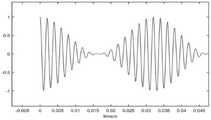
图3为由Matlab离线生成的正弦调幅音时域波形图;Fig. 3 is the sinusoidal amplitude modulation tone time-domain waveform chart generated by Matlab off-line;
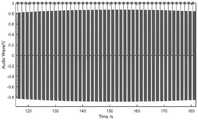
图4为单次将音频采集通道时域波形转化为事件触发标记信号的示意图;Fig. 4 is a schematic diagram of converting the time-domain waveform of the audio acquisition channel into an event-triggered marker signal once;
图5为多次将音频采集通道时域波形转化为事件触发标记信号的示意图。FIG. 5 is a schematic diagram of converting time-domain waveforms of an audio acquisition channel into event-triggered marker signals multiple times.
具体实施方式Detailed ways
下面将结合本发明实施例中的附图,对本发明实施例中的技术方案进行清楚、完整地描述,显然,所描述的实施例仅仅是本发明一部分实施例,而不是全部的实施例。基于本发明中的实施例,本领域普通技术人员在没有做出创造性劳动前提下所获得的所有其他实施例,都属于本发明保护的范围。The following will clearly and completely describe the technical solutions in the embodiments of the present invention with reference to the accompanying drawings in the embodiments of the present invention. Obviously, the described embodiments are only some, not all, embodiments of the present invention. Based on the embodiments of the present invention, all other embodiments obtained by persons of ordinary skill in the art without making creative efforts belong to the protection scope of the present invention.
本发明的目的是提供一种用于脑磁听觉诱发场测试的触发标记装置及方法,以解决传统的触发标记方法对计算机软件平台的依赖性较大,且需要单独配置环境变量不便于随时随地使用、需要台式机或者拓展坞使便携性受到限制、时间精度有较大的延迟、欠缺稳定性的问题。The purpose of the present invention is to provide a trigger marking device and method for brain magnetic auditory evoked field testing to solve the problem that the traditional trigger marking method is more dependent on the computer software platform, and it is not convenient to configure environment variables separately anytime and anywhere The use and need of a desktop or docking station restricts portability, time accuracy has a large delay, and lacks stability.
为使本发明的上述目的、特征和优点能够更加明显易懂,下面结合附图和具体实施方式对本发明作进一步详细的说明。In order to make the above objects, features and advantages of the present invention more comprehensible, the present invention will be further described in detail below in conjunction with the accompanying drawings and specific embodiments.
实施例一Embodiment one
如图1所示,本发明提供的用于脑磁听觉诱发场测试的触发标记装置,包括:音频信号产生模块、双路同步输出功率放大装置、电流-声音换能单元、脑磁信号测量系统以及数据处理计算机。As shown in Fig. 1, the trigger marking device for the magnetic brain auditory evoked field test provided by the present invention includes: an audio signal generation module, a dual-channel synchronous output power amplification device, a current-sound transduction unit, and a magnetic brain signal measurement system and data processing computers.
音频信号产生模块用于产生触发音频信号,其输出端与具备数模转换功能的双路同步输出功率放大装置的输入端相连。The audio signal generation module is used to generate trigger audio signals, and its output end is connected with the input end of a dual-channel synchronous output power amplification device with digital-to-analog conversion function.
双路同步输出功率放大装置的一个输出端将功率放大后触发音频信号输出至电流-声音换能单元的输入端,另一个输出端将数模转换后的触发音频信号接入多通道信号采集装置的输入端。One output end of the dual-channel synchronous output power amplifier device amplifies the power and outputs the trigger audio signal to the input end of the current-sound transducer unit, and the other output end connects the trigger audio signal after digital-to-analog conversion to the multi-channel signal acquisition device input terminal.
电流-声音换能单元用于将数模转换后的触发音频信号转换为声音信号。The current-sound transducing unit is used for converting the digital-to-analog converted trigger audio signal into a sound signal.
脑磁信号测量系统的输入端与电流-声音换能单元的输出端连接,用于测量受试者在声音信号刺激下产生的脑部磁场信号;脑磁信号测量系统的输出端与双路同步输出功率放大装置的输出端并行接入多通道信号采集装置的输入端。The input end of the magnetic brain signal measurement system is connected to the output end of the current-sound transduction unit, which is used to measure the brain magnetic field signal generated by the subject under the stimulation of the sound signal; the output end of the magnetic brain signal measurement system is synchronized with the two-way The output end of the output power amplification device is connected in parallel to the input end of the multi-channel signal acquisition device.
多通道信号采集装置用于同步采集数模转换后的触发音频信号和脑部磁场信号。The multi-channel signal acquisition device is used for synchronously acquiring the digital-to-analog converted trigger audio signal and brain magnetic field signal.
数据处理计算机与多通道信号采集装置连接,用于对数模转换后的触发音频信号进行处理确定事件触发标记,并基于事件触发标记对脑部磁场信号进行分段叠加处理。The data processing computer is connected with the multi-channel signal acquisition device, and is used to process the digital-to-analog converted trigger audio signal to determine the event trigger mark, and perform segmental superposition processing on the brain magnetic field signal based on the event trigger mark.
本发明提供的装置在脑磁系统必需的功率放大器和信号采集装置的基础上,增设具备数模转换功能的双路同步输出功率放大装置,不增加硬件设备,对计算机硬件限制大大减小,提高了便携性和兼容性。The device provided by the present invention is based on the necessary power amplifier and signal acquisition device of the magnetic brain system, and a dual-channel synchronous output power amplification device with digital-to-analog conversion function is added, without adding hardware equipment, greatly reducing computer hardware restrictions and improving portability and compatibility.
作为一个可选地实施例,双路同步输出功率放大装置包括:通信模块、主控芯片、DA模块以及功放模块。As an optional embodiment, the dual-channel synchronous output power amplification device includes: a communication module, a main control chip, a DA module, and a power amplifier module.
通信模块与音频信号产生模块连接,通信模块用于实现该装置和音频信号产生模块之间的通信解码,并将触发音频信号传输到主控芯片。The communication module is connected with the audio signal generation module, and the communication module is used to realize the communication decoding between the device and the audio signal generation module, and transmit the trigger audio signal to the main control chip.
主控芯片用于实现控制、驱动DA模块和通信模块。The main control chip is used to realize control, drive DA module and communication module.
DA模块用于对触发音频信号进行数模转换,实现音频数字信号转化为电流(电压)信号以及双输出通道间的同步。The DA module is used for digital-to-analog conversion of the trigger audio signal to realize the conversion of the audio digital signal into a current (voltage) signal and the synchronization between the dual output channels.
功放模块与DA模块连接,用于对数模转换后的触发音频信号进行放大,并将放大后的数模转换后的触发音频信号发送至电流-声音换能单元。功放模块能够提高DA模块的带载能力,驱动后端电流-声音换能单元输出更大声压等级的声音。The power amplifier module is connected with the DA module for amplifying the digital-to-analog converted trigger audio signal, and sending the amplified digital-to-analog converted trigger audio signal to the current-sound transducing unit. The power amplifier module can improve the loading capacity of the DA module, and drive the back-end current-sound transducer unit to output a sound with a higher sound pressure level.
作为一个可选地实施例,脑磁信号测量系统包括:磁强计探头阵列、磁强计控制器以及磁强计控制计算机。As an optional embodiment, the magnetic brain signal measurement system includes: a magnetometer probe array, a magnetometer controller, and a magnetometer control computer.
磁强计探头阵列与磁强计控制器通过编织排线固定连接,用于放置在受试者头部近处测量受试者受声音信号刺激产生的脑部磁场信号。每个探头测得的脑部磁场信号分为X轴和Y轴两路,与数模转换后的触发音频信号一同作为输入接入多通道信号采集装置。The magnetometer probe array is fixedly connected to the magnetometer controller through a braided cable, and is used to place near the subject's head to measure the brain magnetic field signal of the subject stimulated by the sound signal. The brain magnetic field signal measured by each probe is divided into X-axis and Y-axis two channels, which together with the digital-to-analog converted trigger audio signal are used as input to the multi-channel signal acquisition device.
磁强计控制器用于将脑部磁场信号发送至多通道信号采集装置。The magnetometer controller is used to send the brain magnetic field signal to the multi-channel signal acquisition device.
磁强计控制计算机通过数字特定协议接口与磁强计控制器接口间导线连接,建立通信协议,实现通信和控制功能。The magnetometer control computer is connected with the wire between the interface of the magnetometer controller through a digital specific protocol interface to establish a communication protocol to realize communication and control functions.
作为一个可选地实施例,通道信号采集装置包括多个AD板卡、DAQ控制机箱和上位机;AD板卡分别与DA模块以及磁强计控制器连接,多个AD板卡还与DAQ控制机箱通过排针与排针座连接,DAQ控制机箱用于控制多个AD板卡同步采集数模转换后的触发音频信号和脑部磁场信号,并将采集到的数模转换后的触发音频信号和脑部磁场信号统一编码后以特定协议传输至上位机进行存储和显示。As an optional embodiment, the channel signal acquisition device includes a plurality of AD boards, a DAQ control chassis and an upper computer; the AD boards are respectively connected with the DA module and the magnetometer controller, and the multiple AD boards are also connected with the DAQ control The chassis is connected with the pin header, and the DAQ control chassis is used to control multiple AD boards to synchronously collect the digital-to-analog converted trigger audio signal and brain magnetic field signal, and collect the digital-to-analog converted trigger audio signal It is uniformly coded with the brain magnetic field signal and then transmitted to the host computer with a specific protocol for storage and display.
作为一个可选地实施例,通信模块通过第一输入音频接口与音频信号产生模块进行通信;功放模块通过第一输出音频接口OUT1与电流-声音换能单元通信,DA模块通过第二输出音频接口OUT2与AD板卡进行通信;第一输入音频接口、第一输出音频接口以及第二输出音频接口均为3.5mm音频接口。As an optional embodiment, the communication module communicates with the audio signal generating module through the first input audio interface; the power amplifier module communicates with the current-sound transducing unit through the first output audio interface OUT1, and the DA module communicates with the current-sound transducer unit through the second output audio interface OUT2 communicates with the AD board; the first input audio interface, the first output audio interface and the second output audio interface are all 3.5mm audio interfaces.
磁强计控制器通过第三输出音频接口与AD板卡进行通信;第三输出音频接口为2.5mm音频接口。The magnetometer controller communicates with the AD board through the third output audio interface; the third output audio interface is a 2.5mm audio interface.
AD板卡通过第二输入音频接口与第二输出音频接口以及第三输出音频接口连接;第三输出音频接口为2.5mm音频接口。The AD board is connected to the second output audio interface and the third output audio interface through the second input audio interface; the third output audio interface is a 2.5mm audio interface.
实施例二Embodiment two
本发明还提供了一种用于脑磁听觉诱发场测试的触发标记方法,方法应用于上述用于脑磁听觉诱发场测试的触发标记装置,如图2所示,处理流程如下:The present invention also provides a trigger marking method for the brain magneto-auditory evoked field test, the method is applied to the above-mentioned trigger mark device for the brain magneto-auditory induced field test, as shown in Figure 2, the processing flow is as follows:
S1:从所有通道数据中提取触发音频信号所在通道数据。S1: Extract the channel data of the trigger audio signal from all channel data.
S2:设定阈值对触发音频信号进行二值化处理。S2: Set a threshold to perform binarization processing on the trigger audio signal.
S3:基于触发音频信号的波形特性设置判定条件,并基于判定条件对二值化处理后的触发音频进行遴选并标记为事件触发起始点。S3: Set a judgment condition based on the waveform characteristics of the trigger audio signal, and select and mark the binarized trigger audio based on the judgment condition as an event trigger start point.
S4:将事件触发标记依据后续数据处理格式要求进行配置并替换掉触发音频信号所在通道数据。S4: Configure the event trigger flag according to the subsequent data processing format requirements and replace the channel data where the trigger audio signal is located.
S5:根据事件触发标记对脑部磁场信号进行分段叠加处理。S5: Perform segmentation and superposition processing on the brain magnetic field signal according to the event-triggered marker.
具体的,首先在存储的数据中提取触发音频信号所在通道的原始数据进行分析,对比如图3所示的音频时域波形,图4所示的固定采样率下的触发音频采集通道数据的音频基本特性没有变化,可以依据音频波形特性设置阈值,通过逻辑数组对数据进行二值化(0和1)。依据音频基本特性设置判定条件,只将满足事件触发起始点判定条件的1保留,即一个触发事件仅保留一个事件触发起始点,单次刺激识别结果和采集波形绘制在同一幅图如图4所示,多次刺激识别结果和采集波形绘制在同一幅图如图5所示。采集音频与原音频一定存在差异,识别结果可以进行手动校正。还需要在二值化的基础上将触发信号配置为便于后续数据处理的格式。Specifically, first extract the original data of the channel where the trigger audio signal is located in the stored data for analysis, compare the audio time domain waveform shown in Figure 3, and the audio data of the trigger audio acquisition channel data at a fixed sampling rate shown in Figure 4 The basic characteristics have not changed, and the threshold can be set according to the characteristics of the audio waveform, and the data is binarized (0 and 1) through a logical array. Set the judgment conditions according to the basic characteristics of the audio, and only keep 1 that meets the judgment conditions of the event trigger start point, that is, only one event trigger start point is reserved for a trigger event, and the single stimulus recognition result and the collected waveform are drawn in the same picture as shown in Figure 4 As shown in Figure 5, the recognition results of multiple stimuli and the acquired waveforms are plotted in the same picture. There must be differences between the collected audio and the original audio, and the recognition results can be manually corrected. It is also necessary to configure the trigger signal into a format convenient for subsequent data processing on the basis of binarization.
本发明对采样频率有一定要求,采样频率不应为刺激音频中各频率分量的倍频,以避免音频谐波信号在奈奎斯特频率附近产生的拍频信号对采集到的音频产生低频调制,导致幅值不准确,音频采集出现包络;同时采样频率应至少为刺激音频中最高频成分的两倍,避免音频采集欠采样,无法获得波形完全形态。The present invention has certain requirements on the sampling frequency, and the sampling frequency should not be the frequency multiplier of each frequency component in the stimulating audio, so as to avoid low-frequency modulation of the collected audio by the beat frequency signal generated by the audio harmonic signal near the Nyquist frequency , resulting in inaccurate amplitude and enveloped audio acquisition; at the same time, the sampling frequency should be at least twice that of the highest frequency component in the stimulus audio to avoid undersampling of audio acquisition and the inability to obtain a complete waveform.
本发明采用简单阈值及特征判断算法实现音频信号转化为触发标记的过程,只需要对音频信号特征有了解,不需要单独配置环境变量,便于非编程专业临床研究人员使用。The invention adopts a simple threshold value and feature judgment algorithm to realize the process of converting audio signals into trigger marks. It only needs to know the characteristics of audio signals and does not need to configure environment variables separately, which is convenient for non-programming professional clinical researchers to use.
本说明书中各个实施例采用递进的方式描述,每个实施例重点说明的都是与其他实施例的不同之处,各个实施例之间相同相似部分互相参见即可。Each embodiment in this specification is described in a progressive manner, each embodiment focuses on the difference from other embodiments, and the same and similar parts of each embodiment can be referred to each other.
本文中应用了具体个例对本发明的原理及实施方式进行了阐述,以上实施例的说明只是用于帮助理解本发明的方法及其核心思想;同时,对于本领域的一般技术人员,依据本发明的思想,在具体实施方式及应用范围上均会有改变之处。综上所述,本说明书内容不应理解为对本发明的限制。In this paper, specific examples have been used to illustrate the principle and implementation of the present invention. The description of the above embodiments is only used to help understand the method of the present invention and its core idea; meanwhile, for those of ordinary skill in the art, according to the present invention Thoughts, there will be changes in specific implementation methods and application ranges. In summary, the contents of this specification should not be construed as limiting the present invention.
Claims (8)
Priority Applications (1)
| Application Number | Priority Date | Filing Date | Title |
|---|---|---|---|
| CN202211293848.9ACN115624332B (en) | 2022-10-21 | 2022-10-21 | Trigger marking device and method for magnetoencephalic hearing induced field test |
Applications Claiming Priority (1)
| Application Number | Priority Date | Filing Date | Title |
|---|---|---|---|
| CN202211293848.9ACN115624332B (en) | 2022-10-21 | 2022-10-21 | Trigger marking device and method for magnetoencephalic hearing induced field test |
Publications (2)
| Publication Number | Publication Date |
|---|---|
| CN115624332Atrue CN115624332A (en) | 2023-01-20 |
| CN115624332B CN115624332B (en) | 2024-07-05 |
Family
ID=84906872
Family Applications (1)
| Application Number | Title | Priority Date | Filing Date |
|---|---|---|---|
| CN202211293848.9AActiveCN115624332B (en) | 2022-10-21 | 2022-10-21 | Trigger marking device and method for magnetoencephalic hearing induced field test |
Country Status (1)
| Country | Link |
|---|---|
| CN (1) | CN115624332B (en) |
Cited By (1)
| Publication number | Priority date | Publication date | Assignee | Title |
|---|---|---|---|---|
| CN119375601A (en)* | 2024-12-30 | 2025-01-28 | 杭州爱华仪器有限公司 | A test system and method for an auditory brainstem response measuring instrument |
Citations (5)
| Publication number | Priority date | Publication date | Assignee | Title |
|---|---|---|---|---|
| CN106768284A (en)* | 2016-12-20 | 2017-05-31 | 西安科技大学 | A kind of abnormal sound source judges and alignment system and method |
| CN111543949A (en)* | 2020-05-13 | 2020-08-18 | 北京航空航天大学 | A diagnostic device for children's ASD based on magnetoencephalography and electroencephalography |
| EP3970617A1 (en)* | 2020-09-22 | 2022-03-23 | Health Tech Connex Inc. | Methods and apparatus for triggering a stimulus for evoked brain response analysis |
| CN114287944A (en)* | 2021-12-02 | 2022-04-08 | 北京航空航天大学杭州创新研究院 | Electrical stimulation induced nerve magnetic signal acquisition and analysis device and method |
| CN114870192A (en)* | 2022-03-26 | 2022-08-09 | 天津工业大学 | Analysis method for regulating and controlling synaptic plasticity LTP (Low temperature plasticity) by music rhythm magnetic field generated by pink (soothing) song |
- 2022
- 2022-10-21CNCN202211293848.9Apatent/CN115624332B/enactiveActive
Patent Citations (5)
| Publication number | Priority date | Publication date | Assignee | Title |
|---|---|---|---|---|
| CN106768284A (en)* | 2016-12-20 | 2017-05-31 | 西安科技大学 | A kind of abnormal sound source judges and alignment system and method |
| CN111543949A (en)* | 2020-05-13 | 2020-08-18 | 北京航空航天大学 | A diagnostic device for children's ASD based on magnetoencephalography and electroencephalography |
| EP3970617A1 (en)* | 2020-09-22 | 2022-03-23 | Health Tech Connex Inc. | Methods and apparatus for triggering a stimulus for evoked brain response analysis |
| CN114287944A (en)* | 2021-12-02 | 2022-04-08 | 北京航空航天大学杭州创新研究院 | Electrical stimulation induced nerve magnetic signal acquisition and analysis device and method |
| CN114870192A (en)* | 2022-03-26 | 2022-08-09 | 天津工业大学 | Analysis method for regulating and controlling synaptic plasticity LTP (Low temperature plasticity) by music rhythm magnetic field generated by pink (soothing) song |
Non-Patent Citations (1)
| Title |
|---|
| 苗英章;魏欣;王宝山;孙吉林;吴杰;李素敏;: "老年人大脑听觉皮质脑磁图对刺激声频率和强度的反应", 中国组织工程研究与临床康复, no. 13, 1 April 2007 (2007-04-01)* |
Cited By (1)
| Publication number | Priority date | Publication date | Assignee | Title |
|---|---|---|---|---|
| CN119375601A (en)* | 2024-12-30 | 2025-01-28 | 杭州爱华仪器有限公司 | A test system and method for an auditory brainstem response measuring instrument |
Also Published As
| Publication number | Publication date |
|---|---|
| CN115624332B (en) | 2024-07-05 |
Similar Documents
| Publication | Publication Date | Title |
|---|---|---|
| CN108471973B (en) | Method and apparatus for wideband phase gradient signal acquisition | |
| Sun et al. | A low-cost smartphone-based electrochemical biosensor for point-of-care diagnostics | |
| US5791342A (en) | Medical data transmission system | |
| CN103845051A (en) | Multi-channel ecg measurement | |
| CN101822540A (en) | Myoelectricity amplifier and method for sampling myoelectricity signals | |
| CN102727196A (en) | Measurement apparatus, measurement method, information processing apparatus, and information processing method | |
| CN102735890A (en) | Test system, test signal auxiliary device and test signal generation method thereof | |
| CN115624332B (en) | Trigger marking device and method for magnetoencephalic hearing induced field test | |
| JP2002125939A (en) | Uterine activity monitor and its operation method | |
| US20250235161A1 (en) | System and method for controlling physical systems using brain waves | |
| CN103356183A (en) | ECG acquisition platform | |
| CN118870240A (en) | Control method, device and storage medium of wearable device | |
| CN101716074B (en) | Evoked potential recorder based on time characteristic indicators | |
| CN107970031B (en) | High-flux multichannel electrophysiological signal recording and stimulating system | |
| CN213302364U (en) | Multichannel microelectrode bioimpedance test system | |
| CN112075932B (en) | High-resolution time-frequency analysis method for evoked potential signals | |
| CN208339513U (en) | Intelligent biological information acquisition system | |
| CN100571616C (en) | Lead wire ECG machine | |
| KR20230025958A (en) | Synchronous electrocardiograms created apparatus using two lead asynchronous electrocardiograms | |
| CN2922792Y (en) | Automatic epilepsia electroencephalo monitoring and diagnosis system | |
| CN207676149U (en) | A kind of EEG signal simulation generating device | |
| CN218783877U (en) | Microphone testing device | |
| Kartsch et al. | Using Low-Power, Low-Cost IoT Processors in Clinical Biosignal Research: An In-depth Feasibility Check | |
| CN118568610B (en) | Signal acquisition system, marking device and storage medium for fNIRS and EEG combined scene | |
| US20250086226A1 (en) | Apparatus and method for reasoning music based on brain computer interface |
Legal Events
| Date | Code | Title | Description |
|---|---|---|---|
| PB01 | Publication | ||
| PB01 | Publication | ||
| SE01 | Entry into force of request for substantive examination | ||
| SE01 | Entry into force of request for substantive examination | ||
| GR01 | Patent grant | ||
| GR01 | Patent grant |